- Securing User Services Overview
- Autosecure
-
-
-
- Configuring RADIUS
- AAA Dead-Server Detection
- ACL Default Direction
- Attribute Screening for Access Requests
- Enable Multilink PPP via RADIUS for Preauthentication User
- Enhanced Test Command
- Framed-Route in RADIUS Accounting
- Offload Server Accounting Enhancement
- Per VRF AAA
- RFC-2867 RADIUS Tunnel Accounting
- RADIUS Attribute Screening
- RADIUS Centralized Filter Management
- RADIUS Debug Enhancements
- RADIUS Logical Line ID
- RADIUS NAS-IP-Address Attribute Configurability
- RADIUS Route Download
- RADIUS Support of 56-Bit Acct Session-Id
- RADIUS Tunnel Preference for Load Balancing and Fail-Over
- RADIUS Server Reorder on Failure
- Tunnel Authentication via RADIUS on Tunnel Terminator
-
-
-
- RADIUS Attributes Overview and RADIUS IETF Attributes
- RADIUS Vendor-Proprietary Attributes
- Vendor-Specific Attributes (VSA) and RADIUS Disconnect-Cause Attribute Values
- Connect-Info RADIUS Attribute 77
- Encrypted Vendor Specific Attributes
- Local AAA Server
- Per-User QoS via AAA Policy Name
- RADIUS Attribute 5 (NAS-Port) Format Specified on a Per-Server Group Level
- RADIUS Attribute 8 (Framed-IP-Address) in Access Requests
- RADIUS Attribute 82: Tunnel Assignment ID
- RADIUS Attribute 104
- RADIUS Progress Codes
- RADIUS Timeout Set During Pre-Authentication
- RADIUS Tunnel Attribute Extensions
- V.92 Reporting Using RADIUS Attribute v.92-info
-
- Cisco IOS Login Enhancements (Login Block)
- Cisco IOS Resilient Configuration
- Image Verification
- IP Source Tracker
- Role-Based CLI Access
- Finding Feature Information
- Contents
- Prerequisites for VPN Access Control Using
802.1X Authentication - Restrictions for VPN Access Control Using 802.1X Authentication
- Information About VPN Access Control Using 802.1X Authentication
- How to Configure VPN Access Control Using 802.1X Authentication
- Configuration Examples for VPN Access Control Using 802.1X Authentication
- Additional References
- Feature Information for VPN Access Control Using 802.1X Authentication
VPN Access Control Using 802.1X Authentication
The home access router provides connectivity to the corporate network through a Virtual Private Network (VPN) tunnel through the Internet. In the home LAN, apart from the employee, other members of the household may also be using the same access router. The VPN Access Control Using 802.1X Authentication feature allows enterprise employees to access their enterprise networks from home while allowing other household members to access only the Internet. The feature uses the IEEE 802.1X protocol framework to achieve the VPN access control. The authenticated employee has access to the VPN tunnel and others (unauthenticated users on the same LAN) have access only to the Internet.
An authentication manager has been added to allow more flexible authentication between different authentication methods like, dot1x, MAC address bypass, and web authentication. See the "802.1x Flexible Authentication" feature for more information.
Finding Feature Information
Your software release may not support all the features documented in this module. For the latest feature information and caveats, see the release notes for your platform and software release. To find information about the features documented in this module, and to see a list of the releases in which each feature is supported, see the "Feature Information for VPN Access Control Using 802.1X Authentication" section.
Use Cisco Feature Navigator to find information about platform support and Cisco software image support. To access Cisco Feature Navigator, go to http://www.cisco.com/go/cfn. An account on Cisco.com is not required.
Contents
•![]() Prerequisites for VPN Access Control Using 802.1X Authentication
Prerequisites for VPN Access Control Using 802.1X Authentication
•![]() Restrictions for VPN Access Control Using 802.1X Authentication
Restrictions for VPN Access Control Using 802.1X Authentication
•![]() Information About VPN Access Control Using 802.1X Authentication
Information About VPN Access Control Using 802.1X Authentication
•![]() How to Configure VPN Access Control Using 802.1X Authentication
How to Configure VPN Access Control Using 802.1X Authentication
•![]() Configuration Examples for VPN Access Control Using 802.1X Authentication
Configuration Examples for VPN Access Control Using 802.1X Authentication
•![]() Feature Information for VPN Access Control Using 802.1X Authentication
Feature Information for VPN Access Control Using 802.1X Authentication
Prerequisites for VPN Access Control Using
802.1X Authentication
•![]() The PCs connecting behind the router should have 802.1X clients running on them.
The PCs connecting behind the router should have 802.1X clients running on them.
•![]() You should know how to configure authentication, authorization, and accounting (AAA) and RADIUS.
You should know how to configure authentication, authorization, and accounting (AAA) and RADIUS.
•![]() You should be familiar with IP Security (IPSec).
You should be familiar with IP Security (IPSec).
•![]() You should be familiar with Dynamic Host Configuration Protocol (DHCP).
You should be familiar with Dynamic Host Configuration Protocol (DHCP).
•![]() You should know how to configure user lists on a Cisco access control server (ACS).
You should know how to configure user lists on a Cisco access control server (ACS).
Restrictions for VPN Access Control Using 802.1X Authentication
•![]() Easy VPN is not supported.
Easy VPN is not supported.
•![]() VLAN interfaces are currently not supported.
VLAN interfaces are currently not supported.
•![]() If there is a switch located between the router and the supplicant (client PC), the Extensible Authentication Protocol over LAN (EAPOL) frames will not reach the router because the switch discards them.
If there is a switch located between the router and the supplicant (client PC), the Extensible Authentication Protocol over LAN (EAPOL) frames will not reach the router because the switch discards them.
Information About VPN Access Control Using 802.1X Authentication
To configure the VPN Access Control Using 802.1X Authentication feature, you should understand the following concepts:
•![]() How VPN Control Using 802.1X Authentication Works
How VPN Control Using 802.1X Authentication Works
•![]() Authentication Using Passwords and MD5
Authentication Using Passwords and MD5
How VPN Control Using 802.1X Authentication Works
The home access router provides connectivity to the corporate network through a VPN tunnel through the Internet. In the home LAN, both authenticated (employee) and unauthenticated (other household members) users exist, and both have access to the corporate VPN tunnel. Currently there is no existing mechanism to prevent the unauthenticated user from accessing the VPN tunnel.
To distinguish between the users, the VPN Access Control Using 802.1X Authentication feature uses the IEEE 802.1X protocol that allows end hosts to send user credentials on Layer 2 of the network operating system. Unauthenticated traffic users will be allowed to pass through the Internet but will be blocked from accessing the corporate VPN tunnel. The VPN Access Control Using 802.1X feature expands the scope of the 802.1X standard to authenticate devices rather than ports, meaning that multiple devices can be independently authenticated for any given port. This feature separates traffic from authenticated and unauthenticated users so that separate access policies can be applied.
When an 802.1X-capable host starts up, it will initiate the authentication phase by sending the EAPOL-Start 802.1X protocol data unit (PDU) to the reserved IEEE multicast MAC address (01-80-C2-00-00-03) with the Ethernet type or length set to 0x888E.
All 802.1X PDUs will be identified as such by the Ethernet driver and will be enqueued to be handled by an 802.1X process. On some platforms, Ethernet drivers have to program the interface address filter so that EAPOL packets can be accepted.
On the router, the receipt of the EAPOL-Start message will result in the source MAC address being "remembered," and an EAPOL-request or identity PDU being sent to the host. The router will send all host-addressed PDUs to the individual MAC address of the host rather than to the multicast address.
802.1X Authentication Sample Topology and Configuration
Figure 1 illustrates a typical scenario in which VPN access control using 802.1X authentication is in place.
Figure 1 Typical 802.1X Authentication Setup
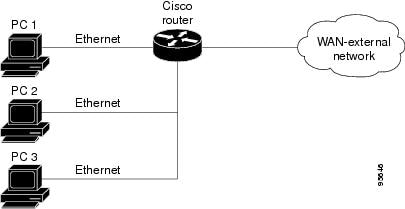
In Figure 1, all the PCs are 802.1X capable hosts, and the Cisco router is an authenticator. All the PCs are connected to the built-in hub or to an external hub. If a PC does not support 802.1X authentication, MAC-based authentication is supported on the Cisco router. You can have any kind of connectivity or network beyond the Cisco router WAN.

Note![]() •
•![]() If there is a switch located between the router and the supplicant (client PC), the EAPOL frames will not reach the router because the switch discards them.
If there is a switch located between the router and the supplicant (client PC), the EAPOL frames will not reach the router because the switch discards them.
•![]() A supplicant is an entity at one end of a point-to-point LAN segment that is being authenticated by an authenticator that is attached to the other end of that link.
A supplicant is an entity at one end of a point-to-point LAN segment that is being authenticated by an authenticator that is attached to the other end of that link.
Converged 802.1X Authenticator Support
The Cisco IOS commands in Cisco IOS Release 12.4(6)T for 802.1X authenticators have been standardized to work the same way on various Cisco IOS platforms.
802.1X Supplicant Support
There are deployment scenarios in which a network device (a router acting as an 802.1X authenticator) is placed in an unsecured location and cannot be trusted as an authenticator. This scenario requires that a network device be able to authenticate itself against another network device. The 802.1X supplicant support functionality provides the following solutions for this requirement:
•![]() An Extensible Authentication Protocol (EAP) framework has been included so that the supplicant has the ability to "understand" and "respond" to EAP requests. EAP-Message Digest 5 (EAP-MD5) is currently supported.
An Extensible Authentication Protocol (EAP) framework has been included so that the supplicant has the ability to "understand" and "respond" to EAP requests. EAP-Message Digest 5 (EAP-MD5) is currently supported.
•![]() Two network devices that are connected through an Ethernet link can act as a supplicant and as an authenticator simultaneously, thus providing mutual authentication capability.
Two network devices that are connected through an Ethernet link can act as a supplicant and as an authenticator simultaneously, thus providing mutual authentication capability.
•![]() A network device that is acting as a supplicant can authenticate itself with more than one authenticator (that is, a single port on a supplicant can be connected to multiple authenticators).
A network device that is acting as a supplicant can authenticate itself with more than one authenticator (that is, a single port on a supplicant can be connected to multiple authenticators).
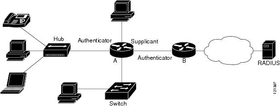
The following illustration is an example of 802.1X supplicant support. The illustration shows that a single supplicant port has been connected to multiple authenticators. Router A is acting as an authenticator to devices that are sitting behind it on the LAN while those devices are acting as supplicants. At the same time, Router B is an authenticator to Router A (which is acting as a supplicant). The RADIUS server is located in the enterprise network.
When Router A tries to authenticate devices on the LAN, it needs to "talk" to the RADIUS server, but before it can allow access to any of the devices that are sitting behind it, it has to prove its identity to Router B. Router B checks the credential of Router A and gives access.
Figure 2 Multiple Instances of Supplicant Support
Converged 802.1X Supplicant Support
The Cisco IOS commands in Cisco IOS Release 12.4(6)T for 802.1X supplicants have been standardized to work the same way on various Cisco IOS platforms. See the "Configuring a Router As an 802.1x Supplicant" section.
Authentication Using Passwords and MD5
For information about using passwords and Message Digest 5 (MD5), see the following document on Cisco.com:
•![]() Improving Security on Cisco Routers
Improving Security on Cisco Routers
How to Configure VPN Access Control Using 802.1X Authentication
This section includes the following procedures:
•![]() Configuring a AAA RADIUS Server
Configuring a AAA RADIUS Server
•![]() Configuring a PC As an 802.1x Supplicant
Configuring a PC As an 802.1x Supplicant
•![]() Monitoring VPN Access Control Using 802.1X Authentication
Monitoring VPN Access Control Using 802.1X Authentication
•![]() Verifying VPN Access Control Using 802.1X Authentication
Verifying VPN Access Control Using 802.1X Authentication
Configuring a AAA RADIUS Server
To configure an AAA RADIUS server, perform the following steps.
Step 1 ![]() Configure entries for the network access server and associated shared secrets.
Configure entries for the network access server and associated shared secrets.
Note ![]() The AAA server can be FreeRADIUS or Cisco Secure ACS or any other similar product with 802.1X support.
The AAA server can be FreeRADIUS or Cisco Secure ACS or any other similar product with 802.1X support.
Step 2 ![]() Add the username and configure the password of the user.
Add the username and configure the password of the user.
Step 3 ![]() Configure a global or per-user authentication scheme.
Configure a global or per-user authentication scheme.
Configuring a Router
This section contains the following procedures:
•![]() Enabling 802.1X Authentication (required)
Enabling 802.1X Authentication (required)
•![]() Configuring Router and RADIUS Communication (required)
Configuring Router and RADIUS Communication (required)
•![]() Configuring 802.1X Parameters (Retransmissions and Timeouts) (optional)
Configuring 802.1X Parameters (Retransmissions and Timeouts) (optional)
•![]() Configuring the Identity Profile (required)
Configuring the Identity Profile (required)
•![]() Configuring the Virtual Template and DHCP (required)
Configuring the Virtual Template and DHCP (required)
•![]() Configuring the Necessary Access Control Policies (optional)
Configuring the Necessary Access Control Policies (optional)
Enabling 802.1X Authentication
To enable 802.1X port-based authentication, you should configure the router so that it can communicate with the AAA server, enable 802.1X globally, and enable 802.1X on the interface. To enable 802.1X port-based authentication, perform the following steps.
SUMMARY STEPS
1. ![]() enable
enable
2. ![]() configure terminal
configure terminal
3. ![]() aaa new-model
aaa new-model
4. ![]() aaa authentication dot1x {default | listname} method1 [method2...]
aaa authentication dot1x {default | listname} method1 [method2...]
5. ![]() dot1x system-auth-control
dot1x system-auth-control
6. ![]() identity profile default
identity profile default
7. ![]() interface type slot/port
interface type slot/port
8. ![]() dot1x port-control auto
dot1x port-control auto
DETAILED STEPS
Example
This section provides the following examples:
•![]() Verifying 802.1X Authentication
Verifying 802.1X Authentication
802.1X Configuration
The following example shows that 802.1X authentication has been configured on a router:
Router# configure terminal
Router(config)# aaa new-model
Router(config)# aaa authentication dot1x default group radius group radius
Router(config)# dot1x system-auth-control
Router(config)# interface fastethernet 1
Router(config-if)# dot1x port-control auto
Verifying 802.1X Authentication
The following show dot1x command sample output shows that 802.1X authentication has been configured on a router:
Router# show dot1x all
Sysauthcontrol Enabled
Dot1x Protocol Version 2
Dot1x Info for FastEthernet1
-----------------------------------
PAE = AUTHENTICATOR
PortControl = AUTO
ControlDirection = Both
HostMode = MULTI_HOST
ReAuthentication = Enabled
QuietPeriod = 600
ServerTimeout = 60
SuppTimeout = 30
ReAuthPeriod = 1800 (Locally configured)
ReAuthMax = 2
MaxReq = 3
TxPeriod = 60
RateLimitPeriod = 60
Configuring Router and RADIUS Communication
To configure RADIUS server parameters, perform the following steps.
SUMMARY STEPS
1. ![]() enable
enable
2. ![]() configure terminal
configure terminal
3. ![]() ip radius source-interface interface-name
ip radius source-interface interface-name
4. ![]() radius-server host {hostname | ip-address}
radius-server host {hostname | ip-address}
5. ![]() radius-server key string
radius-server key string
DETAILED STEPS
Example
The following example shows that RADIUS server parameters have been configured on the router:
Router# configure terminal
Router(config)# ip radius source-interface ethernet1
Router(config)# radius-server host 192.0.2.1
Router(config)# radius-server key radiuskey
Configuring 802.1X Parameters (Retransmissions and Timeouts)
Various 802.1X retransmission and timeout parameters can be configured. Because all of these parameters have default values, configuring them is optional. To configuring the retransmission and timeout parameters, perform the following steps.
SUMMARY STEPS
1. ![]() enable
enable
2. ![]() configure terminal
configure terminal
3. ![]() interface type slot/port
interface type slot/port
4. ![]() dot1x max-req number-of-retries
dot1x max-req number-of-retries
5. ![]() dot1x port-control [auto | force-authorized | force-unauthorized]
dot1x port-control [auto | force-authorized | force-unauthorized]
6. ![]() dot1x control-direction {both | in}
dot1x control-direction {both | in}
7. ![]() dot1x reauthentication
dot1x reauthentication
8. ![]() dot1x timeout tx-period seconds
dot1x timeout tx-period seconds
9. ![]() dot1x timeout server-timeout seconds
dot1x timeout server-timeout seconds
10. ![]() dot1x timeout reauth-period seconds
dot1x timeout reauth-period seconds
11. ![]() dot1x timeout quiet-period seconds
dot1x timeout quiet-period seconds
12. ![]() dot1x timeout ratelimit-period seconds
dot1x timeout ratelimit-period seconds
DETAILED STEPS
Example
The following configuration example shows that various retransmission and timeout parameters have been configured:
Router# configure terminal
Router(config)# interface FastEthernet1
Router(config-if)# dot1x port-control auto
Router(config-if)# dot1x reauthentication
Router(config-if)# dot1x timeout reauth-period 1800
Router(config-if)# dot1x timeout quiet-period 600
Router(config-if)# dot1x timeout supp-timeout 60
Router(config-if)# dot1x timeout server-timeout 60
Configuring the Identity Profile
The identity profile default command allows you to configure the static MAC addresses of the client that do not support 802.1X and to authorize or unauthorize them statically. The VPN Access Control Using 802.1X Authentication feature allows authenticated and unauthenticated users to be mapped to different interfaces. Under the dot1x profile configuration mode, you can specify the virtual template interface that should be used to create the virtual-access interface to which unauthenticated supplicants will be mapped. To specify which virtual template interface should be used to create the virtual access interface, perform the following steps.
SUMMARY STEPS
1. ![]() enable
enable
2. ![]() configure terminal
configure terminal
3. ![]() identity profile default
identity profile default
4. ![]() description line-of-description
description line-of-description
5. ![]() template virtual-template
template virtual-template
6. ![]() device [authorize | not-authorize] mac-address mac-address
device [authorize | not-authorize] mac-address mac-address
7. ![]() device authorize type device-type
device authorize type device-type
DETAILED STEPS
Example
The following example shows that Cisco IP phones and a specific MAC address have been statically authorized:
Router# configure terminal
Router (config)# identity profile default
Router(config-1x-prof)# description put the description here
Router(config-1x-prof)# template virtual-template1
Router(config-1x-prof)# device authorize type cisco ip phone
Router(config-1x-prof)# device authorize mac-address 0001.024B.B4E7
Configuring the Virtual Template and DHCP
The VPN Access Control Using 802.1X Authentication feature can be configured with one DHCP pool or two. If there are two pools, the unauthenticated and authenticated devices will get their addresses from separate DHCP pools. For example, the public pool can have an address block that has only local significance, and the private pool can have an address that is routable over the VPN tunnel. To configure your router for a private pool and for a public pool, perform the following steps.
SUMMARY STEPS
Configuring the Identity Profile
1. ![]() enable
enable
2. ![]() configure terminal
configure terminal
3. ![]() identity profile default
identity profile default
4. ![]() description description-string
description description-string
5. ![]() template virtual-template
template virtual-template
6. ![]() exit
exit
Configuring the DHCP Private Pool
1. ![]() ip dhcp pool name
ip dhcp pool name
2. ![]() network network-number [mask]
network network-number [mask]
3. ![]() default-router address
default-router address
Configuring the DHCP Public Pool
1. ![]() ip dhcp pool name
ip dhcp pool name
2. ![]() network network-number [mask]
network network-number [mask]
3. ![]() default-router address
default-router address
4. ![]() exit
exit
Configuring the Interface
1. ![]() configure terminal
configure terminal
2. ![]() interface type slot/port
interface type slot/port
3. ![]() ip address ip-address mask [secondary]
ip address ip-address mask [secondary]
4. ![]() interface virtual-template number
interface virtual-template number
5. ![]() ip address ip-address mask [secondary]
ip address ip-address mask [secondary]
6. ![]() exit
exit
Configuring an Interface Without Assigning an Explicit IP Address to the Interface
1. ![]() enable
enable
2. ![]() configure terminal
configure terminal
3. ![]() interface type slot/port
interface type slot/port
4. ![]() ip unnumbered type number
ip unnumbered type number
DETAILED STEPS
Configuring the Identity Profile
Configuring the DHCP Private Pool
Configuring the DHCP Public Pool
Configuring the Interface
Configuring an Interface Without Assigning an Explicit IP Address to the Interface
Example
The following example shows that the identity profile associates virtual-template1 with unauthenticated supplicants. Virtual-template1 gets its IP address from interface loopback 0, and unauthenticated supplicants are associated with a public pool. Authenticated users are associated with a private pool.
Router(config)# identity profile default
Router(config-identity-prof)# description put the description here
Router(config-identity-prof)# template virtual-template1
Router(config-identity-prof)# exit
Router(config)# ip dhcp pool private
Router(dhcp-config)# default-router 192.0.2.0
Router(dhcp-config)# exit
Router(config)#ip dhcp pool public
Router(dhcp-config)# default-router 192.0.2.1
Router(dhcp-config)# exit
Router(config)# interface
Router(dhcp-config)# network 209.165.200.225 255.255.255.224
Router(dhcp-config)# default-router 192.0.2.1
Router(dhcp-config)# exit
Router(config)# interface loopback0
Router(config-if)# interface ethernet0
Router(config-if)# ip address 209.165.200.226 255.255.255.224
Router(config-if)# exit
Router(config)# interface virtual-template1
Router(config-if)# ip unnumbered loopback 0
Configuring the Necessary Access Control Policies
802.1X authentication separates traffic from authenticated and unauthenticated devices. Traffic from authenticated devices transit through the physical interface, and unauthenticated traffic transits through the Virtual-Template1. Therefore, different policies can be applied on each interface. The configuration will also depend on whether two DHCP pools or a single DHCP pool is being used. If a single DHCP pool is being used, access control can be configured on Virtual-Template1, which will block any traffic from going to the networks to which unauthenticated devices should not have access. These networks (to which unauthenticated devices should not have access) could be the corporate subnetworks protected by the VPN or encapsulated by generic routing encapsulation (GRE). There can also be access control that restricts the access between authenticated and unauthenticated devices.
If two pools are configured, the traffic from a non-trusted pool is routed to the Internet using Network Address Translation (NAT), whereas trusted pool traffic is forwarded through a VPN tunnel. The routing can be achieved by configuring ACLs used by NAT and VPN accordingly.
For an example of an access control policy configuration, see the "Access Control Policies: Example" section.
Configuring a PC As an 802.1x Supplicant
This section includes the following procedures.
•![]() Configuring a PC for VPN Access Control Using 802.1X Authentication
Configuring a PC for VPN Access Control Using 802.1X Authentication
•![]() Enabling 802.1X Authentication on a Windows 2000/XP PC
Enabling 802.1X Authentication on a Windows 2000/XP PC
•![]() Enabling 802.1X Authentication on a Windows 2000 PC
Enabling 802.1X Authentication on a Windows 2000 PC
•![]() Enabling 802.1X Authentication on a Windows XP PC
Enabling 802.1X Authentication on a Windows XP PC
•![]() Enabling 802.1X Authentication on Windows 2000 and Windows XP PCs
Enabling 802.1X Authentication on Windows 2000 and Windows XP PCs
Configuring a PC for VPN Access Control Using 802.1X Authentication
To configure your PC for VPN Access Control Using 802.1X Authentication, perform the following steps.
Step 1 ![]() Enable 802.1X for MD5.
Enable 802.1X for MD5.
Step 2 ![]() Enable DHCP.
Enable DHCP.
Enabling 802.1X Authentication on a Windows 2000/XP PC
802.1X implementation on a Windows 2000/XP PC is unstable. A more stable 802.1X client, AEGIS (beta) for Microsoft Windows, is available at the Meetinghouse Data Communications website at www.mtghouse.com.
Enabling 802.1X Authentication on a Windows 2000 PC
To enable 802.1X authentication on your Windows 2000 PC, perform the following steps.
Step 1 ![]() Make sure that the PC has at least Service Pack 3.
Make sure that the PC has at least Service Pack 3.
Go to the page "Microsoft 802.1x Authentication Client" on the Microsoft Windows 2000 website at the following URL:
http://www.microsoft.com/windows2000/server/evaluation/news/bulletins/8021xclient.asp.
At the above site, download and install 802.1X client for Windows 2000.
If the above site is unavailable, search for the "Q313664: Recommended Update" page on the Microsoft Windows 2000 website at the following URL: http://www.microsoft.com/windows2000/downloads/recommended/q313664/default.asp
Step 2 ![]() Reboot your PC after installing the client.
Reboot your PC after installing the client.
Step 3 ![]() Go to the Microsoft Windows registry and add or install the following entry:
Go to the Microsoft Windows registry and add or install the following entry:
"HKLM\Software\Microsoft\EAPOL\Parameters\General\Global\SupplicantMode REG_DWORD 3"
("SupplicantMode" key entry is not there by default under Global option in the registry. So add a new entry named "SupplicantMode" as REG_DOWORD and then set its value to 3.)
Step 4 ![]() Reboot your PC.
Reboot your PC.
Enabling 802.1X Authentication on a Windows XP PC
To enable 802.1X authentication on a Windows XP PC, perform the following steps.
Step 1 ![]() Go to the Microsoft Windows registry and install the following entry there:
Go to the Microsoft Windows registry and install the following entry there:
"HKLM\Software\Microsoft\EAPOL\Parameters\General\Global\SupplicantMode REG_DWORD 3"
Step 2 ![]() Reboot your PC.
Reboot your PC.
Enabling 802.1X Authentication on Windows 2000 and Windows XP PCs
To enable 802.1X authentication on Windows 2000 and Windows XP PCs, that is, if you are operating both at the same time, perform the following steps.
Step 1 ![]() Open the Network and Dial-up Connections window on your computer.
Open the Network and Dial-up Connections window on your computer.
Step 2 ![]() Right-click the Ethernet interface (Local Area Connection) to open the properties window. It should have a tab called "Authentication."
Right-click the Ethernet interface (Local Area Connection) to open the properties window. It should have a tab called "Authentication."
Click the Authentication tab. Select the check box titled "Enable network access control using IEEE 802.1X."
In a short period of time you should see a dialog box (for Windows 2000) or a floating window asking you to select it. Select it, and when the next window appears, enter the username and password in this dialog box. See Figure 3.
Figure 3 Local Area Connection Properties Window

Configuring a Router As an 802.1x Supplicant
To configure a router as an 802.1x supplicant, perform the following steps.
SUMMARY STEPS
1. ![]() enable
enable
2. ![]() configure terminal
configure terminal
3. ![]() aaa authentication dot1x {default | listname} method1 [method2...]
aaa authentication dot1x {default | listname} method1 [method2...]
4. ![]() dot1x credentials name
dot1x credentials name
5. ![]() username name
username name
6. ![]() password [0 | 7] password
password [0 | 7] password
7. ![]() interface type number
interface type number
8. ![]() dot1x pae supplicant
dot1x pae supplicant
9. ![]() dot1x credentials name
dot1x credentials name
10. ![]() end
end
DETAILED STEPS
Troubleshooting Tips
Use the debug commands in the Monitoring VPN Access Control Using 802.1X Authentication section to debug the supplicant.
Monitoring VPN Access Control Using 802.1X Authentication
To monitor VPN Access Control Using 802.1X Authentication, perform the following steps. The commands shown in the steps may be used one at a time and in no particular order.
SUMMARY STEPS
1. ![]() enable
enable
2. ![]() clear dot1x {all | interface}
clear dot1x {all | interface}
3. ![]() clear eap sessions [credentials credentials-name | interface interface-name | method method-name | transport transport-name]]
clear eap sessions [credentials credentials-name | interface interface-name | method method-name | transport transport-name]]
4. ![]() debug dot1x [all | errors | events | feature | packets | redundancy | registry | state-machine]
debug dot1x [all | errors | events | feature | packets | redundancy | registry | state-machine]
5. ![]() debug eap [all | method] [authenticator | peer] {all | errors | events | packets | sm}
debug eap [all | method] [authenticator | peer] {all | errors | events | packets | sm}
6. ![]() dot1x initialize [interface interface-name]
dot1x initialize [interface interface-name]
7. ![]() dot1x re-authenticate interface-type interface-number
dot1x re-authenticate interface-type interface-number
DETAILED STEPS
Verifying VPN Access Control Using 802.1X Authentication
To verify VPN Access Control Using 802.1X Authentication, perform the following steps.
SUMMARY STEPS
1. ![]() enable
enable
2. ![]() show dot1x [interface interface-name [details]]
show dot1x [interface interface-name [details]]
3. ![]() show eap registrations [method | transport]
show eap registrations [method | transport]
4. ![]() show eap sessions [credentials credentials-name | interface interface-name | method method-name | transport transport-name]
show eap sessions [credentials credentials-name | interface interface-name | method method-name | transport transport-name]
DETAILED STEPS
Configuration Examples for VPN Access Control Using 802.1X Authentication
This section includes the following example:
•![]() Typical VPN Access Control Using 802.1X Configuration: Example
Typical VPN Access Control Using 802.1X Configuration: Example
•![]() Access Control Policies: Example
Access Control Policies: Example
Typical VPN Access Control Using 802.1X Configuration: Example
The following sample output shows that VPN access control using 802.1X authentication has been configured. Output is shown for the router and for the gateway.
Router
Router# show running-config
Building configuration...
Current configuration : 2457 bytes
!
version 12.4
no service pad
service timestamps debug datetime msec
service timestamps log datetime msec
no service password-encryption
!
hostname 871-1
!
boot-start-marker
boot-end-marker
!
logging message-counter syslog
!
aaa new-model
!
!
aaa authentication dot1x default group radius group radius
!
!
aaa session-id common
!
!
dot11 syslog
ip source-route
!
ip dhcp pool private
network 209.165.200.225 255.255.255.224
default-router 192.0.2.18
!
ip dhcp pool public
network 209.165.200.226 255.255.255.224
default-router 192.0.2.17
!
ip dhcp pool name
default-router 192.0.2.16
!
!
ip cef
no ip domain lookup
ip host sjc-tftp02 192.0.2.15
ip host sjc-tftp01 192.0.2.14
ip host dirt 192.0.2.13
!
!
!
template virtualtemplate1
!
dot1x system-auth-control
dot1x credentials basic-user
description This credentials profile should be used for most configured ports
username router1
password 0 secret
!
identity profile default
description description 1
device authorize mac-address 0001.024b.b4e7
device authorize mac-address 0001.0001.0001
device authorize type cisco ip phone
template Virtual-Template1
!
!
!
!
!
archive
log config
hidekeys
!
!
!
!
!
interface Loopback0
ip address 209.165.200.227 255.255.255.224
!
interface FastEthernet0
!
interface FastEthernet1
dot1x pae authenticator
dot1x port-control auto
dot1x timeout quiet-period 600
dot1x timeout server-timeout 60
dot1x timeout reauth-period 1800
dot1x timeout tx-period 60
dot1x timeout ratelimit-period 60
dot1x max-req 3
dot1x reauthentication
!
interface FastEthernet2
!
interface FastEthernet3
!
interface FastEthernet4
no ip address
shutdown
duplex auto
speed auto
!
interface Virtual-Template1
ip unnumbered Loopback0
!
interface Dot11Radio0
no ip address
shutdown
speed basic-1.0 basic-2.0 basic-5.5 6.0 9.0 basic-11.0 12.0 18.0 24.0 36.0 48.0
station-role root
no cdp enable
!
interface Vlan1
ip address 209.165.200.228 255.255.255.224
!
ip default-gateway 192.0.2.10
ip default-network 192.0.2.11
ip forward-protocol nd
ip route 0.0.0.0 0.0.0.0 192.0.2.11
ip route 209.165.200.229 255.255.255.224 192.0.2.12
no ip http server
no ip http secure-server
!
!
ip radius source-interface FastEthernet1
!
!
!
radius-server host 192.0.2.9 auth-port 1645 acct-port 1646
radius-server key radiuskey
!
control-plane
!
!
line con 0
exec-timeout 30 0
logging synchronous
no modem enable
line aux 0
line vty 0 4
privilege level 15
password lab
!
scheduler max-task-time 5000
end
Peer Router As Gateway
Router# show running-config
Building configuration...
Current configuration: 1828 bytes
!
version 12.3
service timestamps debug datetime msec
service timestamps log datetime msec
no service password-encryption
!
hostname c3725
!
!
no aaa new-model
ip subnet-zero
!
vpdn enable
!
vpdn-group 1
accept-dialin
protocol pppoe
virtual-template 1
!
mpls ldp logging neighbor-changes
!
crypto isakmp policy 1
authentication pre-share
crypto isakmp key 0 test address 192.0.2.8
!
!
crypto ipsec transform-set t1 ah-md5-hmac esp-des
crypto mib ipsec flowmib history tunnel size 2
crypto mib ipsec flowmib history failure size 2
!
crypto map test 1 ipsec-isakmp
set peer 192.0.2.7
set transform-set t1
match address 101
!
no voice hpi capture buffer
no voice hpi capture destination
!
interface Loopback0
description corporate
ip address 209.165.200.230 255.255.255.224
!
interface Loopback1
description internet
ip address 209.165.200.231 255.255.255.224
!
interface FastEthernet0/0
ip address 209.165.200.232 255.255.255.224
duplex auto
speed auto
!
interface FastEthernet0/1
no ip address
speed auto
half-duplex
pppoe enable
!
interface ATM1/0
ip address 209.165.200.233 255.255.255.224
no atm ilmi-keepalive
pvc 1/43
protocol ip 192.0.2.6 broadcast
encapsulation aal5snap
!
!
interface FastEthernet2/0
no ip address
speed auto
full-duplex
!
interface FastEthernet2/1
no ip address
shutdown
duplex auto
speed auto
!
interface Virtual-Template1
ip address 209.165.200.234 255.255.255.224
ip mtu 1492
crypto map test
!
!
router rip
network 192.0.2.5
network 192.0.2.4
network 192.0.2.3
network 192.0.2.2
network 192.0.2.1
!
ip http server
no ip http secure-server
ip classless
!
access-list 101 permit ip 10.5.0.0 0.0.0.255 10.0.0.1 0.0.0.255
no cdp log mismatch duplex
!
line con 0
exec-timeout 0 0
line aux 0
line vty 0 4
login
!
!
end
Access Control Policies: Example
The following output example shows that access control policies have been configured.
Single DHCP pool
ip dhcp pool private
network 209.165.200.236 255.255.255.224
default-router 20.0.0.1
exit
crypto isakmp policy 1
authentication pre-share
!
crypto isakmp key test address address
crypto ipsec transform-set t1 esp-3des esp-sha-hmac
mode tunnel
crypto map test 1 ipsec-isakmp
set peer address
set transform-set t1
match address 101
access-list 101 permit ip 10.0.0.0 0.0.0.255 50.0.0.0 0.0.0.255
access-list 102 deny ip 10.0.0.0 0.0.0.255 50.0.0.0 0.0.0.255
access-list 102 permit ip any any
!
interface Ethernet0
! inside interface
! dot1x configs
!
interface Virtual-Template1
! Deny traffic from going to VPN
ip access-group 102 in
!
Interface Ethernet1
! outside interface
crypto map test
Two DHCP Pools
ip dhcp pool private
network 209.165.200.237 255.255.255.224
default-router 192.0.2.1
exit
!
ip dhcp pool public
network 209.165.200.238 255.255.255.224
default-router 192.0.2.0
exit
!
crypto isakmp policy 1
authentication pre-share
!
crypto isakmp key test address address
crypto ipsec transform-set t1 esp-3des esp-sha-hmac
mode tunnel
crypto map test 1 ipsec-isakmp
set peer address
set transform-set t1
match address 101
access-list 101 permit ip 10.0.0.0 0.0.0.255 10.10.0.0 0.0.0.255
access-list 102 permit ip 10.0.0.1 0.0.0.255 any
!
interface Ethernet0
!inside interface
! dot1x configs
!
interface Loopback0
ip address 209.165.200.239 255.255.255.224
!
interface Virtual-Template1
ip unnumbered Loopback0
ip nat inside
!
Interface Ethernet1
! outside interface
crypto map test
ip nat outside
!
ip nat inside source list 102 interface Ethernet1 overload
Additional References
Related Documents
|
|
|
|---|---|
Configuring 802.1X port-based authentication |
|
DHCP |
"DHCP Features Roadmap" module in the Cisco IOS IP Addressing Services Configuration Guide |
IPSec |
Cisco IOS Security Configuration Guide: Secure Connectivity, Release 15.0. |
RADIUS |
"Configuring RADIUS" module. |
Security commands |
|
User lists on a Cisco ACS |
User Guide for Cisco Secure ACS for Windows Server Version 3.2. |
Standards
|
|
|
|---|---|
IEEE 802.1X protocol |
— |
MIBs
|
|
|
|---|---|
None. |
To locate and download MIBs for selected platforms, Cisco IOS releases, and feature sets, use Cisco MIB Locator found at the following URL: |
RFCs
|
|
|
|---|---|
RFC-2284 |
"RFC 2284 (PPP Extensible Authentication Protocol [EAP])" document from The Internet Requests for Comments (RFC) document series |
Technical Assistance
Feature Information for VPN Access Control Using 802.1X Authentication
Table 1 lists the features in this module.
Use Cisco Feature Navigator to find information about platform support and software image support. Cisco Feature Navigator enables you to determine which software images support a specific software release, feature set, or platform. To access Cisco Feature Navigator, go to http://www.cisco.com/go/cfn. An account on Cisco.com is not required.
Note ![]() Table 1 lists only the software release that introduced support for a given feature in a given software release train. Unless noted otherwise, subsequent releases of that software release train also support that feature.
Table 1 lists only the software release that introduced support for a given feature in a given software release train. Unless noted otherwise, subsequent releases of that software release train also support that feature.
 Feedback