- Finding Feature Information
- Contents
- Prerequisites for Stateful Failover for IPsec
- Restrictions for Stateful Failover for IPsec
- Information About Stateful Failover for IPsec
- How to Use Stateful Failover for IPsec
Stateful Failover for IPsec
Stateful failover for IP Security (IPsec) enables a router to continue processing and forwarding IPsec packets after a planned or unplanned outage occurs. Customers employ a backup (secondary) router that automatically takes over the tasks of the active (primary) router if the active router loses connectivity for any reason. This process is transparent to the user and does not require adjustment or reconfiguration of any remote peer.
Stateful failover for IPsec is designed to work in conjunction with stateful switchover (SSO) and Hot Standby Routing Protocol (HSRP). HSRP provides network redundancy for IP networks, ensuring that user traffic immediately and transparently recovers from failures in network edge devices or access circuits. That is, HSRP monitors both the inside and outside interfaces so that if either interface goes down, the whole router is deemed to be down and ownership of Internet Key Exchange (IKE) and IPsec security associations (SAs) is passed to the standby router (which transitions to the HSRP active state). SSO allows the active and standby routers to share IKE and IPsec state information so that each router has enough information to become the active router at any time. To configure stateful failover for IPsec, a network administrator should enable HSRP, assign a virtual IP address, and enable the SSO protocol.
Finding Feature Information
Your software release may not support all the features documented in this module. For the latest feature information and caveats, see the release notes for your platform and software release. To find information about the features documented in this module, and to see a list of the releases in which each feature is supported, see the "Feature Information for Stateful Failover for IPsec" section.
Use Cisco Feature Navigator to find information about platform support and Cisco IOS and Catalyst OS software image support. To access Cisco Feature Navigator, go to http://www.cisco.com/go/cfn. An account on Cisco.com is not required.
Contents
•![]() Prerequisites for Stateful Failover for IPSec, page 2
Prerequisites for Stateful Failover for IPSec, page 2
•![]() Restrictions for Stateful Failover for IPSec, page 2
Restrictions for Stateful Failover for IPSec, page 2
•![]() Information About Stateful Failover for IPSec, page 3
Information About Stateful Failover for IPSec, page 3
•![]() How to Use Stateful Failover for IPSec, page 6
How to Use Stateful Failover for IPSec, page 6
•![]() Configuration Examples for Stateful Failover, page 27
Configuration Examples for Stateful Failover, page 27
•![]() Additional References, page 36
Additional References, page 36
•![]() Feature Information for Stateful Failover for IPsec
Feature Information for Stateful Failover for IPsec
Prerequisites for Stateful Failover for IPsec
Complete, Duplicate IPsec and IKE Configuration on the Active and Standby Devices
This document assumes that you have a complete IKE and IPsec configuration. (This document describes only how to add stateful failover to a working IPsec configuration.)
The IKE and IPsec configuration that is set up on the active device must be duplicated on the standby device. That is, the crypto configuration must be identical with respect to Internet Security Association and Key Management Protocol (ISAKMP) policy, ISAKMP keys (preshared), IPsec profiles, IPsec transform sets, all crypto map sets that are used for stateful failover, all access control lists (ACLs) that are used in match address statements on the crypto map sets, all AAA configurations used for crypto, client configuration groups, ip local pools used for crypto, and ISAKMP profiles.

Note ![]() None of the configuration information between the active and standby device is automatically transferred; the user is responsible for ensuring that the crypto configurations match on both devices. If the crypto configurations on both devices do not match, failover from the active device to the standby device will not be successful.
None of the configuration information between the active and standby device is automatically transferred; the user is responsible for ensuring that the crypto configurations match on both devices. If the crypto configurations on both devices do not match, failover from the active device to the standby device will not be successful.
Device Requirements
•![]() Stateful failover for IPsec requires that your network contains two identical routers that are available to be either the primary or secondary device. Both routers should be the same type of device, have the same CPU and memory, and have either no encryption accelerator or identical encryption accelerators.
Stateful failover for IPsec requires that your network contains two identical routers that are available to be either the primary or secondary device. Both routers should be the same type of device, have the same CPU and memory, and have either no encryption accelerator or identical encryption accelerators.
•![]() This feature is currently supported only on a limited number of platforms. To check the latest platform support, go to Cisco Feature Navigator at http://tools.cisco.com/ITDIT/CFN/jsp/index.jsp.
This feature is currently supported only on a limited number of platforms. To check the latest platform support, go to Cisco Feature Navigator at http://tools.cisco.com/ITDIT/CFN/jsp/index.jsp.
Restrictions for Stateful Failover for IPsec
When configuring redundancy for a virtual private network (VPN), the following restrictions exist:
•![]() Both the active and standby devices must run the identical version of the Cisco IOS software, and both the active and standby devices must be connected via hub or switch.
Both the active and standby devices must run the identical version of the Cisco IOS software, and both the active and standby devices must be connected via hub or switch.
•![]() The Cisco Integrated Services Routers (ISRs) and the VPN modules that support stateful failover for IPsec are as follows:
The Cisco Integrated Services Routers (ISRs) and the VPN modules that support stateful failover for IPsec are as follows:
–![]() The AIM-VPN/BPII-PLUS and AIM-VPN/SSL-1 hardware encryption modules are supported in a Cisco 1841 router.
The AIM-VPN/BPII-PLUS and AIM-VPN/SSL-1 hardware encryption modules are supported in a Cisco 1841 router.
–![]() The AIM-VPN/EPII-Plus and AIM-VPN/SSL-2 hardware encryption modules are supported in Cisco 2801, 2811, 2821 and 2851 routers.
The AIM-VPN/EPII-Plus and AIM-VPN/SSL-2 hardware encryption modules are supported in Cisco 2801, 2811, 2821 and 2851 routers.
–![]() The AIM-VPN/EPII+ and AIM-VPN/SSL-3 hardware encryption modules are supported in a Cisco 3825 router.
The AIM-VPN/EPII+ and AIM-VPN/SSL-3 hardware encryption modules are supported in a Cisco 3825 router.
–![]() The AIM-VPN/HPII+ and AIM-VPN/SSL3 hardware encryption modules are supported in a Cisco 3845 router.
The AIM-VPN/HPII+ and AIM-VPN/SSL3 hardware encryption modules are supported in a Cisco 3845 router.
–![]() The VPN Acceleration Module (VAM) and VAM2 hardware encryption modules are supported in a Cisco 7200 series router.
The VPN Acceleration Module (VAM) and VAM2 hardware encryption modules are supported in a Cisco 7200 series router.
•![]() Only "box-to-box" failover is supported; that is, intrachassis failover is currently not supported.
Only "box-to-box" failover is supported; that is, intrachassis failover is currently not supported.
•![]() WAN interfaces between the active (primary) router and the standby (secondary) router are not supported. (HSRP requires inside interfaces and outside interfaces to be connected via LANs.)
WAN interfaces between the active (primary) router and the standby (secondary) router are not supported. (HSRP requires inside interfaces and outside interfaces to be connected via LANs.)
•![]() Load balancing is not supported; that is, no more than one device in a redundancy group can be active at any given time.
Load balancing is not supported; that is, no more than one device in a redundancy group can be active at any given time.
•![]() Stateful failover of IPsec with Layer 2 Tunneling Protocol (L2TP) is not supported.
Stateful failover of IPsec with Layer 2 Tunneling Protocol (L2TP) is not supported.
•![]() Public key infrastructure (PKI) is not supported when used with stateful failover. (Only preshared keys for IKE are supported.)
Public key infrastructure (PKI) is not supported when used with stateful failover. (Only preshared keys for IKE are supported.)
•![]() IKE keepalives are not supported. (Enabling this functionality will cause the connection to be torn down after the standby router assumes ownership control.) However, dead peer detection (DPD) and periodic DPD are supported.
IKE keepalives are not supported. (Enabling this functionality will cause the connection to be torn down after the standby router assumes ownership control.) However, dead peer detection (DPD) and periodic DPD are supported.
•![]() IPsec idle timers are not supported when used with stateful failover.
IPsec idle timers are not supported when used with stateful failover.
•![]() A stateful failover crypto map applied to an interface in a virtual route forwarding (VRF) instance is not supported. However, VRF-aware IPsec features are supported when a stateful failover crypto map is applied to an interface in the global VRF.
A stateful failover crypto map applied to an interface in a virtual route forwarding (VRF) instance is not supported. However, VRF-aware IPsec features are supported when a stateful failover crypto map is applied to an interface in the global VRF.
•![]() Stateful failover is not compatible or interoperable with the State Synchronization Protocol (SSP) version of stateful failover (which is available in Cisco IOS Release 12.2YX1 and Cisco IOS Release 12.2SU).
Stateful failover is not compatible or interoperable with the State Synchronization Protocol (SSP) version of stateful failover (which is available in Cisco IOS Release 12.2YX1 and Cisco IOS Release 12.2SU).
Information About Stateful Failover for IPsec
To configure stateful failover for VPNs, you should understand the following concepts:
•![]() Supported Deployment Scenarios: Stateful Failover for IPsec, page 3
Supported Deployment Scenarios: Stateful Failover for IPsec, page 3
•![]() IPSec Stateful Failover for Remote Access Connections, page 5
IPSec Stateful Failover for Remote Access Connections, page 5
•![]() Dead Peer Detection with IPsec High Availability
Dead Peer Detection with IPsec High Availability
Supported Deployment Scenarios: Stateful Failover for IPsec
It is recommended that you implement IPsec stateful failover in one of the following recommended deployment scenarios—a single interface scenario or a dual interface scenario.
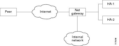
In a single interface scenario, the VPN gateways use one LAN connection for both encrypted traffic arriving from remote peers and decrypted traffic flowing to inside hosts (see Figure 1). The single interface design allows customers to save money on router ports and subnets. This design is typically used if all traffic flowing in and out of the organization does not traverse the VPN routers.
Figure 1 Single Interface Network Topology
In a dual interface scenario, a VPN gateway has more than one interface, enabling traffic to flow in and out of the router via separate interfaces (see Figure 2). This scenario is typically used if traffic flowing in and out of a site must traverse the routers, so the VPN routers will provide the default route out of the network.
Figure 2 Dual Interface Network Topology
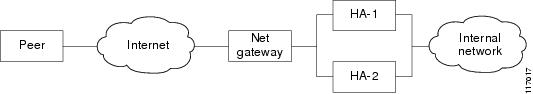
Table 1 lists the functionality available in both a single interface scenario and a dual interfaces scenario.
IPsec Stateful Failover for Remote Access Connections
The main difference between a remote access and a LAN-to-LAN connection is the use of Xauth and mode-config. IKE Xauth is often used to authenticate the user. IKE mode-config is often used to push security policy from the hub (concentrator) router to the user's IPsec implementation. Mode-config is also typically used to assign an internal company network IP address to a user.
In addition to the differences between a remote access configuration and a LAN-to-LAN configuration, you should note the following remote-access-server-specific functions:
•![]() Assigned IP address—The IP address can be assigned to the client via one of the following options:
Assigned IP address—The IP address can be assigned to the client via one of the following options:
–![]() Local IP pools. For local IP pools, the administrator must first configure identical local IP address pools on each router in the high availability (HA) pair (via the ip local pool client-address-pool command). This pool name can be applied in one of two places—in a group policy via the crypto isakmp client configuration group group-name (and the submode command pool pool-name) or in a client configuration via the crypto isakmp client configuration address-pool local local-pool command.
Local IP pools. For local IP pools, the administrator must first configure identical local IP address pools on each router in the high availability (HA) pair (via the ip local pool client-address-pool command). This pool name can be applied in one of two places—in a group policy via the crypto isakmp client configuration group group-name (and the submode command pool pool-name) or in a client configuration via the crypto isakmp client configuration address-pool local local-pool command.
–![]() RADIUS-assigned address. If you are using RADIUS authentication and the RADIUS server returns the Framed-IP-Address attribute, the concentrator will always assign that address to the client. It is recommended that you refer to your RADIUS server vendor's documentation, especially for vendors that allow you to configure address pools on the RADIUS server. Typically those servers require crypto accounting to work properly.
RADIUS-assigned address. If you are using RADIUS authentication and the RADIUS server returns the Framed-IP-Address attribute, the concentrator will always assign that address to the client. It is recommended that you refer to your RADIUS server vendor's documentation, especially for vendors that allow you to configure address pools on the RADIUS server. Typically those servers require crypto accounting to work properly.
To enable accounting on the HA pair, you should issue the following commands on both Active and Standby devices: aaa accounting network radius-accounting start-stop group radius then apply radius-accounting either to the crypto isakmp profile or the crypto map set.
•![]() RADIUS NAS-IP address—The HA pair should appear as a single device to the RADIUS server. Thus, both HA routers must communicate with the RADIUS server using the same IP address. However, when communicating with the RADIUS server, the router must use a physical IP address, not a virtual IP (VIP) address as the NAS-IP address of the router. To configure the RADIUS NAS-IP address for the HA pair, you must configure the same loopback address in the HA pair via interface loopback ip address command; thereafter, you must issue the ip radius source-interface loopback command in the HA pair. Finally, add the new loopback IP address to the RADIUS servers configuration so the RADIUS server can process requests from the HA pair.
RADIUS NAS-IP address—The HA pair should appear as a single device to the RADIUS server. Thus, both HA routers must communicate with the RADIUS server using the same IP address. However, when communicating with the RADIUS server, the router must use a physical IP address, not a virtual IP (VIP) address as the NAS-IP address of the router. To configure the RADIUS NAS-IP address for the HA pair, you must configure the same loopback address in the HA pair via interface loopback ip address command; thereafter, you must issue the ip radius source-interface loopback command in the HA pair. Finally, add the new loopback IP address to the RADIUS servers configuration so the RADIUS server can process requests from the HA pair.
For additional information on how to configure IPsec stateful failover for a remote access connection, see the section "Configuring IPSec Stateful Failover for an Easy VPN Server: Example" in this document.
Dead Peer Detection with IPsec High Availability
To configure Dead Peer Detection (DPD) with IPsec High Availability (HA), it is recommended that you use a value other than the default (2 seconds). A keepalive time of 10 seconds with 5 retries seems to work well with HA because of the time it takes for the router to get into active mode.
To configure DPD with IPsec HA, use the crypto isakmp keepalive command.
How to Use Stateful Failover for IPsec
This section contains the following procedures:
•![]() Enabling HSRP: IP Redundancy and a Virtual IP Address, page 6 (required)
Enabling HSRP: IP Redundancy and a Virtual IP Address, page 6 (required)
•![]() Enabling SSO, page 9 (required)
Enabling SSO, page 9 (required)
•![]() Configuring Reverse Route Injection on a Crypto Map, page 13 (required)
Configuring Reverse Route Injection on a Crypto Map, page 13 (required)
•![]() Enabling Stateful Failover for IKE and IPSec, page 15 (required)
Enabling Stateful Failover for IKE and IPSec, page 15 (required)
•![]() Protecting SSO Traffic, page 18 (optional)
Protecting SSO Traffic, page 18 (optional)
•![]() Managing and Verifying High Availability Information, page 20 (optional)
Managing and Verifying High Availability Information, page 20 (optional)
Enabling HSRP: IP Redundancy and a Virtual IP Address
HSRP provides two services—IP redundancy and a VIP address. Each HSRP group may provide either or both of these services. IPsec stateful failover uses the IP redundancy services from only one HSRP standby group. It can use the VIP address from one or more HSRP groups. Use the following task to configure HSRP on the outside and inside interfaces of the router.
Note ![]() Perform this task on both routers (active and standby) and of both interfaces on each router.
Perform this task on both routers (active and standby) and of both interfaces on each router.
Note ![]() You must perform at least one of the prerequisite steps for correct HSRP operation.
You must perform at least one of the prerequisite steps for correct HSRP operation.
Note ![]() Each time an active device relinquishes control to become the standby device, the active device will reload. This functionality ensures that the state of the new standby device synchronizes correctly with the new active device.
Each time an active device relinquishes control to become the standby device, the active device will reload. This functionality ensures that the state of the new standby device synchronizes correctly with the new active device.
Prerequisites for Spanning Tree Protocol and HSRP Stability
If a switch connects the active and standby routers, you must perform one of the following steps to ensure that the correct settings are configured on that switch:
•![]() Enable the spanning-tree portfast command on every switch port that connects to a HSRP-enabled router interface.
Enable the spanning-tree portfast command on every switch port that connects to a HSRP-enabled router interface.
•![]() Disable the Spanning Tree Protocol (STP) on the switch only if your switch does not connect to other switches. Disabling spanning tree in a multi-switch environment may cause network instability.
Disable the Spanning Tree Protocol (STP) on the switch only if your switch does not connect to other switches. Disabling spanning tree in a multi-switch environment may cause network instability.
•![]() Enable the standby delay minimum [min-delay] reload [reload-delay] command if you do not have access to the switch. The reload-delay argument should be set to a value of at least 120 seconds. This command must be applied to all HSRP interfaces on both routers.
Enable the standby delay minimum [min-delay] reload [reload-delay] command if you do not have access to the switch. The reload-delay argument should be set to a value of at least 120 seconds. This command must be applied to all HSRP interfaces on both routers.
For more information on HSRP instability, see the Avoiding HSRP Instability in a Switching Environment with Various Router Platforms technical note.
Restrictions
•![]() Both the inside (private) interface and the outside (public) interface must belong to separate HSRP groups, but the HSRP group number can be the same.
Both the inside (private) interface and the outside (public) interface must belong to separate HSRP groups, but the HSRP group number can be the same.
•![]() The state of the inside interface and the outside interface must be the same—both interfaces must be in the active state or standby state; otherwise, the packets will not have a route out of the private network.
The state of the inside interface and the outside interface must be the same—both interfaces must be in the active state or standby state; otherwise, the packets will not have a route out of the private network.
•![]() Standby priorities should be equal on both active and standby routers. If the priorities are not equal, the higher priority router will unnecessarily take over as the active router, negatively affecting uptime.
Standby priorities should be equal on both active and standby routers. If the priorities are not equal, the higher priority router will unnecessarily take over as the active router, negatively affecting uptime.
•![]() The IP addresses on the HSRP-tracked interfaces of the standby and active routers should both be either lower or higher on one router than the other. In the case of equal priorities (an HA requirement), HSRP will assign the active state on the basis of the IP address. If an addressing scheme exists so that the public IP address of Router A is lower than the public IP address of Router B, but the opposite is true for their private interfaces, an active/standby-standby/active split condition could exist which will break connectivity.
The IP addresses on the HSRP-tracked interfaces of the standby and active routers should both be either lower or higher on one router than the other. In the case of equal priorities (an HA requirement), HSRP will assign the active state on the basis of the IP address. If an addressing scheme exists so that the public IP address of Router A is lower than the public IP address of Router B, but the opposite is true for their private interfaces, an active/standby-standby/active split condition could exist which will break connectivity.
SUMMARY STEPS
1. ![]() enable
enable
2. ![]() configure terminal
configure terminal
3. ![]() interface type number
interface type number
4. ![]() standby standby-group-number name standby-group-name
standby standby-group-number name standby-group-name
5. ![]() standby standby-group-number ip ip-address
standby standby-group-number ip ip-address
6. ![]() standby standby-group-number track interface-name
standby standby-group-number track interface-name
7. ![]() standby [group-number] preempt
standby [group-number] preempt
8. ![]() standby [group-number] timers [msec] hellotime [msec] holdtime
standby [group-number] timers [msec] hellotime [msec] holdtime
9. ![]() standby delay minimum [min-delay] reload [reload-delay]
standby delay minimum [min-delay] reload [reload-delay]
10. ![]() Repeat.
Repeat.
DETAILED STEPS
Troubleshooting Tips
To help troubleshoot possible HSRP-related configuration problems, issue any of the following HSRP-related debug commands—debug standby errors, debug standby events, and debug standby packets [terse].
Examples
The following example shows how to configure HSRP on a router:
interface Ethernet0/0
ip address 209.165.201.1 255.255.255.224
standby 1 ip 209.165.201.3
standby 1 preempt
standby 1 name HA-out
standby 1 track Ethernet1/0
standby delay reload 120
What to Do Next
After you have successfully configured HSRP on both the inside and outside interfaces, you should enable SSO as described the in the section "Enabling SSO" section."
Enabling SSO
Use this task to enable SSO, which is used to transfer IKE and IPsec state information between two routers.
SSO: Interacting with IPsec and IKE
SSO is a method of providing redundancy and synchronization for many Cisco IOS applications and features. SSO is necessary for IPsec and IKE to learn about the redundancy state of the network and to synchronize their internal application state with their redundant peers.
Prerequisites
•![]() You should configure HSRP before enabling SSO.
You should configure HSRP before enabling SSO.
•![]() To avoid losing SCTP communication between peers, be sure to include the following commands to the local address section of the SCTP section of the IPC configuration:
To avoid losing SCTP communication between peers, be sure to include the following commands to the local address section of the SCTP section of the IPC configuration:
–![]() retransmit-timeout retran-min [msec] retra-max [msec]
retransmit-timeout retran-min [msec] retra-max [msec]
–![]() path-retransmit max-path-retries
path-retransmit max-path-retries
–![]() assoc-retransmit retries
assoc-retransmit retries
SUMMARY STEPS
1. ![]() enable
enable
2. ![]() configure terminal
configure terminal
3. ![]() redundancy inter-device
redundancy inter-device
4. ![]() scheme standby standby-group-name
scheme standby standby-group-name
5. ![]() exit
exit
6. ![]() ipc zone default
ipc zone default
7. ![]() association 1
association 1
8. ![]() protocol sctp
protocol sctp
9. ![]() local-port local-port-number
local-port local-port-number
10. ![]() local-ip device-real-ip-address [device-real-ip-address2]
local-ip device-real-ip-address [device-real-ip-address2]
11. ![]() retransmit-timeout retran-min [msec] retra-max [msec]
retransmit-timeout retran-min [msec] retra-max [msec]
12. ![]() path-retransmit max-path-retries
path-retransmit max-path-retries
13. ![]() assoc-retransmit retries
assoc-retransmit retries
14. ![]() exit
exit
15. ![]() remote-port remote-port-number
remote-port remote-port-number
16. ![]() remote-ip peer-real-ip-address [peer-real-ip-address2]
remote-ip peer-real-ip-address [peer-real-ip-address2]
DETAILED STEPS
Troubleshooting Tips
To help troubleshoot possible SSO-related configuration problems, issue the debug redundancy command.
Examples
The following example shows how to enable SSO:
!
redundancy inter-device
scheme standby HA-out
!
!
ipc zone default
association 1
no shutdown
protocol sctp
local-port 5000
local-ip 10.0.0.1
retransmit-timeout 300 10000
path-retransmit 10
assoc-retransmit 10
remote-port 5000
remote-ip 10.0.0.2
!
What to Do Next
After you have enabled SSO, you should configure reverse route injection (RRI) on a crypto map as shown in the following section.
Configuring Reverse Route Injection on a Crypto Map
You should configure RRI on all existing crypto maps that you want to use with stateful failover. RRI is used with stateful failover so routers on the inside network can learn about the correct path to the current active device. When failover occurs, the new active device injects the RRI routes into its IP routing table and sends out routing updates to its routing peers.
Use one of the following tasks to configure RRI on a dynamic or static crypto map.
•![]() Configuring RRI on Dynamic Crypto Map, page 13
Configuring RRI on Dynamic Crypto Map, page 13
•![]() Configuring RRI on a Static Crypto Map, page 14
Configuring RRI on a Static Crypto Map, page 14
Configuring RRI on Dynamic Crypto Map
Dynamic crypto map entries, like regular static crypto map entries, are grouped into sets. A set is a group of dynamic crypto map entries all with the same dynamic map name but each with a different dynamic sequence number. Each member of the set may be configured for RRI.
SUMMARY STEPS
1. ![]() enable
enable
2. ![]() configure terminal
configure terminal
3. ![]() crypto dynamic-map map-name seq-num
crypto dynamic-map map-name seq-num
4. ![]() reverse-route
reverse-route
DETAILED STEPS
Configuring RRI on a Static Crypto Map
Static crypto map entries are grouped into sets. A set is a group of static crypto map entries all with the same static map name but each with a different sequence number. Each static crypto map in the map set can be configured for RRI. Use this task to configure RRI on a static crypto map.
SUMMARY STEPS
1. ![]() enable
enable
2. ![]() configure terminal
configure terminal
3. ![]() crypto map map-name seq-num ipsec-isakmp
crypto map map-name seq-num ipsec-isakmp
4. ![]() reverse-route
reverse-route
DETAILED STEPS
Examples
The following example shows how to configure RRI on the static crypto map "to-peer-outside":
crypto map to-peer-outside redundancy replay-interval inbound 1000 outbound 10000
crypto map to-peer-outside 10 ipsec-isakmp
set peer 209.165.200.225
set transform-set trans1
match address peer-outside
reverse-route
What to Do Next
After you have configured RRI, you can enable stateful failover for IPsec and IKE.
Enabling Stateful Failover for IKE and IPsec
Use the following tasks to configure stateful failover for IPsec, IKE, and tunnel protection:
•![]() Enabling Stateful Failover for IKE, page 15
Enabling Stateful Failover for IKE, page 15
•![]() Enabling Stateful Failover for IPSec, page 15
Enabling Stateful Failover for IPSec, page 15
•![]() Enabling Stateful Failover for Tunnel Protection, page 17
Enabling Stateful Failover for Tunnel Protection, page 17
Enabling Stateful Failover for IKE
There is no specific command-line interface (CLI) necessary to enable stateful failover for IKE. It is enabled for a particular VIP address when a stateful failover crypto map is applied to an interface.
Enabling Stateful Failover for IPsec
Use this task to enable stateful failover for IPsec. All IPsec state information is transferred from the active router to the standby router via the SSO redundancy channel that was specified in the task "Enabling SSO."
SUMMARY STEPS
1. ![]() enable
enable
2. ![]() configure terminal
configure terminal
3. ![]() interface type number
interface type number
4. ![]() crypto map map-name [redundancy standby-group-name [stateful]]
crypto map map-name [redundancy standby-group-name [stateful]]
DETAILED STEPS
Troubleshooting Tips
To help troubleshoot possible IPsec HA-related problems, issue the debug crypto ipsec ha [detail] [update] command.
Examples
The following example shows how to configure IPsec stateful failover on the crypto map "to-peer-outside":
interface Ethernet0/0
ip address 209.165.201.1 255.255.255.224
standby 1 ip 209.165.201.3
standby 1 preempt
standby 1 name HA-out
standby 1 track Ethernet1/0
crypto map to-peer-outside redundancy HA-out stateful
Enabling Stateful Failover for Tunnel Protection
Use an existing IPsec profile to configure stateful failover for tunnels using IPsec. (You do not configure the tunnel interface as you would with a crypto map configuration.)
Restrictions
The tunnel source address must be a VIP address, and it must not be an interface name.
SUMMARY STEPS
1. ![]() enable
enable
2. ![]() configure terminal
configure terminal
3. ![]() crypto ipsec profile name
crypto ipsec profile name
4. ![]() redundancy standby-group-name stateful
redundancy standby-group-name stateful
5. ![]() exit
exit
6. ![]() interface tunnel number
interface tunnel number
7. ![]() tunnel protection ipsec profile name
tunnel protection ipsec profile name
8. ![]() tunnel source virtual-ip-address
tunnel source virtual-ip-address
DETAILED STEPS
Examples
The following example shows how to configure stateful failover for tunnel protection:
crypto ipsec profile peer-profile
redundancy HA-out stateful
interface Tunnel1
ip unnumbered Loopback0
tunnel source 209.165.201.3
tunnel destination 10.0.0.5
tunnel protection ipsec profile peer-profile
!
interface Ethernet0/0
ip address 209.165.201.1 255.255.255.224
standby 1 ip 209.165.201.3
standby 1 name HA-out
What to Do Next
After you have configured stateful failover, you can use the CLI to protect, verify, and manage your configurations. For more information on completing these tasks, see the sections "Protecting SSO Traffic" and "Managing and Verifying High Availability Information."
Protecting SSO Traffic
Use this task to secure a redundancy group via an IPsec profile. To configure SSO traffic protection, the active and standby devices must be directly connected to each other via Ethernet networks.
The crypto maps that are automatically generated when protecting SSO traffic are applied to each interface, which corresponds to an IP address that was specified via the local-ip command. Traffic that is destined for an IP address that was specified via the remote-ip command is forced out of the crypto-map-configured interface via an automatically created static host route.
Note ![]() If you are certain that the SSO traffic between the redundancy group runs on a physically secure interface, you do not have to configure SSO traffic protection.
If you are certain that the SSO traffic between the redundancy group runs on a physically secure interface, you do not have to configure SSO traffic protection.
SUMMARY STEPS
1. ![]() enable
enable
2. ![]() configure terminal
configure terminal
3. ![]() crypto isakmp key keystring address peer-address
crypto isakmp key keystring address peer-address
4. ![]() crypto ipsec transform-set transform-set-name transform-set-list
crypto ipsec transform-set transform-set-name transform-set-list
5. ![]() crypto ipsec profile profile-name
crypto ipsec profile profile-name
6. ![]() set transform-set transform-set-name
set transform-set transform-set-name
7. ![]() exit
exit
8. ![]() redundancy inter-device
redundancy inter-device
9. ![]() security ipsec profile-name
security ipsec profile-name
DETAILED STEPS
Examples
The following example shows how to configure SSO traffic protection:
crypto isakmp key cisco123 address 0.0.0.0 0.0.0.0 no-xauth
!
crypto ipsec transform-set trans2 ah-md5-hmac esp-aes
!
crypto ipsec profile sso-secure
set transform-set trans2
!
redundancy inter-device
scheme standby HA-out
security ipsec sso-secure
Managing and Verifying High Availability Information
Use any of the following optional tasks to secure and manage your high availability configurations:
•![]() Managing Anti-Replay Intervals, page 21
Managing Anti-Replay Intervals, page 21
•![]() Managing and Verifying HA Configurations, page 22
Managing and Verifying HA Configurations, page 22
Managing Anti-Replay Intervals
Use this optional task to modify the interval in which an IP redundancy-enabled crypto map forwards anti-replay updates from the active router to the standby router.
SUMMARY STEPS
1. ![]() enable
enable
2. ![]() configure terminal
configure terminal
3. ![]() crypto map map-name redundancy replay-interval inbound in-value outbound out-value
crypto map map-name redundancy replay-interval inbound in-value outbound out-value
DETAILED STEPS
Examples
The following example shows how to modify replay counter intervals between the active and standby devices on the crypto map "to-peer-outside":
crypto map to-peer-outside redundancy replay-interval inbound 1000 outbound 10000
crypto map to-peer-outside 10 ipsec-isakmp
set peer 209.165.200.225
set transform-set trans1
match address peer-outside
Managing and Verifying HA Configurations
Use any of the steps within this optional task to display and verify the high availability configurations.
SUMMARY STEPS
1. ![]() enable
enable
2. ![]() show redundancy [states | inter-device]
show redundancy [states | inter-device]
3. ![]() show crypto isakmp sa [active | standby]
show crypto isakmp sa [active | standby]
4. ![]() show crypto ipsec sa [active | standby]
show crypto ipsec sa [active | standby]
5. ![]() show crypto session [active | standby]
show crypto session [active | standby]
6. ![]() show crypto ha
show crypto ha
7. ![]() clear crypto isakmp [active | standby]
clear crypto isakmp [active | standby]
8. ![]() clear crypto sa [active | standby]
clear crypto sa [active | standby]
9. ![]() clear crypto session [active | standby]
clear crypto session [active | standby]
DETAILED STEPS
Examples
Verifying the Active Device:Examples
Router# show redundancy states
my state = 13 -ACTIVE
peer state = 8 -STANDBY HOT
Mode = Duplex
Unit ID = 0
Split Mode = Disabled
Manual Swact = Enabled
Communications = Up
client count = 7
client_notification_TMR = 30000 milliseconds
keep_alive TMR = 4000 milliseconds
keep_alive count = 0
keep_alive threshold = 7
RF debug mask = 0x0
Router# show crypto isakmp sa active
dst src state conn-id slot status
209.165.201.3 209.165.200.225 QM_IDLE 5 0 ACTIVE
Router# show crypto ipsec sa active
interface:Ethernet0/0
Crypto map tag:to-peer-outside, local addr 209.165.201.3
protected vrf:(none)
local ident (addr/mask/prot/port):(192.168.0.1/255.255.255.255/0/0)
remote ident (addr/mask/prot/port):(172.16.0.1/255.255.255.255/0/0)
current_peer 209.165.200.225 port 500
PERMIT, flags={origin_is_acl,}
#pkts encaps:3, #pkts encrypt:3, #pkts digest:3
#pkts decaps:4, #pkts decrypt:4, #pkts verify:4
#pkts compressed:0, #pkts decompressed:0
#pkts not compressed:0, #pkts compr. failed:0
#pkts not decompressed:0, #pkts decompress failed:0
#send errors 0, #recv errors 0
local crypto endpt.:209.165.201.3, remote crypto endpt.:209.165.200.225
path mtu 1500, media mtu 1500
current outbound spi:0xD42904F0(3559458032)
inbound esp sas:
spi:0xD3E9ABD0(3555306448)
transform:esp-3des ,
in use settings ={Tunnel, }
conn id:2006, flow_id:6, crypto map:to-peer-outside
sa timing:remaining key lifetime (k/sec):(4586265/3542)
HA last key lifetime sent(k):(4586267)
ike_cookies:9263635C CA4B4E99 C14E908E 8EE2D79C
IV size:8 bytes
replay detection support:Y
Status:ACTIVE
inbound ah sas:
spi: 0xF3EE3620(4092474912)
transform: ah-md5-hmac ,
in use settings ={Tunnel, }
conn id: 2006, flow_id: 6, crypto map: to-peer-outside
sa timing: remaining key lifetime (k/sec): (4586265/3542)
HA last key lifetime sent(k): (4586267)
ike_cookies: 9263635C CA4B4E99 C14E908E 8EE2D79C
replay detection support: Y
Status: ACTIVE
inbound pcp sas:
outbound esp sas:
spi: 0xD42904F0(3559458032)
transform: esp-3des ,
in use settings ={Tunnel, }
conn id: 2009, flow_id: 9, crypto map: to-peer-outside
sa timing: remaining key lifetime (k/sec): (4586266/3542)
HA last key lifetime sent(k): (4586267)
ike_cookies: 9263635C CA4B4E99 C14E908E 8EE2D79C
IV size: 8 bytes
replay detection support: Y
Status: ACTIVE
outbound ah sas:
spi: 0x75251086(1965363334)
transform: ah-md5-hmac ,
in use settings ={Tunnel, }
conn id: 2009, flow_id: 9, crypto map: to-peer-outside
sa timing: remaining key lifetime (k/sec): (4586266/3542)
HA last key lifetime sent(k): (4586267)
ike_cookies: 9263635C CA4B4E99 C14E908E 8EE2D79C
replay detection support: Y
Status: ACTIVE
outbound pcp sas:
Router# show crypto session active
Crypto session current status
Interface: Ethernet0/0
Session status: UP-ACTIVE
Peer: 209.165.200.225 port 500
IKE SA: local 209.165.201.3/500 remote 209.165.200.225/500 Active
IKE SA: local 209.165.201.3/500 remote 209.165.200.225/500 Active
IPSEC FLOW: permit ip host 192.168.0.1 host 172.16.0.1
Active SAs: 4, origin: crypto map
Router# show crypto ha
IKE VIP: 209.165.201.3
stamp: 74 BA 70 27 9C 4F 7F 81 3A 70 13 C9 65 22 E7 76
IPSec VIP: 209.165.201.3
IPSec VIP: 255.255.255.253
IPSec VIP: 255.255.255.254
Verifying the Standby Device: Examples
Router# show redundancy states
my state = 8 -STANDBY HOT
peer state = 13 -ACTIVE
Mode = Duplex
Unit ID = 0
Split Mode = Disabled
Manual Swact = Enabled
Communications = Up
client count = 7
client_notification_TMR = 30000 milliseconds
keep_alive TMR = 4000 milliseconds
keep_alive count = 1
keep_alive threshold = 7
RF debug mask = 0x0
Router# show crypto isakmp sa standby
dst src state conn-id slot status
209.165.201.3 209.165.200.225 QM_IDLE 5 0 STDBY
Router# show crypto ipsec sa standby
interface:Ethernet0/0
Crypto map tag:to-peer-outside, local addr 209.165.201.3
protected vrf:(none)
local ident (addr/mask/prot/port):(192.168.0.1/255.255.255.255/0/0)
remote ident (addr/mask/prot/port):(172.16.0.1/255.255.255.255/0/0)
current_peer 209.165.200.225 port 500
PERMIT, flags={origin_is_acl,}
#pkts encaps:0, #pkts encrypt:0, #pkts digest:0
#pkts decaps:0, #pkts decrypt:0, #pkts verify:0
#pkts compressed:0, #pkts decompressed:0
#pkts not compressed:0, #pkts compr. failed:0
#pkts not decompressed:0, #pkts decompress failed:0
#send errors 0, #recv errors 0
local crypto endpt.:209.165.201.3, remote crypto endpt.:209.165.200.225
path mtu 1500, media mtu 1500
current outbound spi:0xD42904F0(3559458032)
inbound esp sas:
spi:0xD3E9ABD0(3555306448)
transform:esp-3des ,
in use settings ={Tunnel, }
conn id:2012, flow_id:12, crypto map:to-peer-outside
sa timing:remaining key lifetime (k/sec):(4441561/3486)
HA last key lifetime sent(k):(4441561)
ike_cookies:00000000 00000000 00000000 00000000
IV size:8 bytes
replay detection support:Y
Status:STANDBY
inbound ah sas:
spi:0xF3EE3620(4092474912)
transform:ah-md5-hmac ,
in use settings ={Tunnel, }
conn id:2012, flow_id:12, crypto map:to-peer-outside
sa timing:remaining key lifetime (k/sec):(4441561/3486)
HA last key lifetime sent(k):(4441561)
ike_cookies:00000000 00000000 00000000 00000000
replay detection support:Y
Status:STANDBY
inbound pcp sas:
outbound esp sas:
spi:0xD42904F0(3559458032)
transform:esp-3des ,
in use settings ={Tunnel, }
conn id:2011, flow_id:11, crypto map:to-peer-outside
sa timing:remaining key lifetime (k/sec):(4441561/3485)
HA last key lifetime sent(k):(4441561)
ike_cookies:00000000 00000000 00000000 00000000
IV size:8 bytes
replay detection support:Y
Status:STANDBY
outbound ah sas:
spi:0x75251086(1965363334)
transform:ah-md5-hmac ,
in use settings ={Tunnel, }
conn id:2011, flow_id:11, crypto map:to-peer-outside
sa timing:remaining key lifetime (k/sec):(4441561/3485)
HA last key lifetime sent(k):(4441561)
ike_cookies:00000000 00000000 00000000 00000000
replay detection support:Y
Status:STANDBY
outbound pcp sas:
Router# show crypto session standby
Crypto session current status
Interface:Ethernet0/0
Session status:UP-STANDBY
Peer:209.165.200.225 port 500
IKE SA:local 209.165.201.3/500 remote 209.165.200.225/500 Active
IPSEC FLOW:permit ip host 192.168.0.1 host 172.16.0.1
Active SAs:4, origin:crypto map
Router# show crypto ha
IKE VIP:209.165.201.3
stamp:74 BA 70 27 9C 4F 7F 81 3A 70 13 C9 65 22 E7 76
IPSec VIP:209.165.201.3
IPSec VIP:255.255.255.253
IPSec VIP:255.255.255.254
ha-R2#
Verifying the Active and Standby SAs: Example
The following sample output shows SAs of both the active and standby devices:
Router# show crypto isakmp sa
dst src state conn-id slot status
209.165.201.3 209.165.200.225 QM_IDLE 2 0 STDBY
10.0.0.1 10.0.0.2 QM_IDLE 1 0 ACTIVE
Configuration Examples for Stateful Failover
This section contains the following comprehensive IPsec stateful failover configuration examples:
•![]() Configuring IPSec Stateful Failover: Example, page 27
Configuring IPSec Stateful Failover: Example, page 27
•![]() Configuring IPSec Stateful Failover for an Easy VPN Server: Example, page 31
Configuring IPSec Stateful Failover for an Easy VPN Server: Example, page 31
Configuring IPsec Stateful Failover: Example
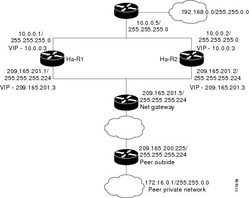
Figure 3 and the following sample outputs from the show running-config command illustrate how to configure stateful failover on two devices—Ha-R1 and Ha-R2.
Figure 3 IPsec Stateful Failover Sample Topology
Stateful Failover Configuration on Ha-R1
Ha-R1# show running-config
Building configuration...
Current configuration :2086 bytes
!
version 12.3
service timestamps debug datetime msec
service timestamps log datetime msec
no service password-encryption
!
hostname ha-R1
!
boot-start-marker
boot-end-marker
!
!
redundancy inter-device
scheme standby HA-out
security ipsec sso-secure
!
logging buffered 10000000 debugging
logging rate-limit console 10000
!
!
ipc zone default
association 1
no shutdown
protocol sctp
local-port 5000
local-ip 10.0.0.1
remote-port 5000
remote-ip 10.0.0.2
!
clock timezone PST 0
no aaa new-model
ip subnet-zero
!
crypto isakmp policy 1
authentication pre-share
crypto isakmp key cisco123 address 0.0.0.0 0.0.0.0 no-xauth
!
!
crypto ipsec transform-set trans1 ah-md5-hmac esp-3des
crypto ipsec transform-set trans2 ah-md5-hmac esp-aes
!
crypto ipsec profile sso-secure
set transform-set trans2
!
!
crypto map to-peer-outside redundancy replay-interval inbound 1000 outbound 10000
crypto map to-peer-outside 10 ipsec-isakmp
set peer 209.165.200.225
set transform-set trans1
match address peer-outside
!
!
!
interface Ethernet0/0
ip address 209.165.201.1 255.255.255.224
standby 1 ip 209.165.201.3
standby 1 preempt
standby 1 name HA-out
standby 1 track Ethernet1/0
standby delay reload 120
crypto map to-peer-outside redundancy HA-out stateful
!
interface Ethernet1/0
ip address 10.0.0.1 255.255.255.0
standby 2 ip 10.0.0.3
standby 2 preempt
standby 2 name HA-in
standby delay reload 120
standby 2 track Ethernet0/0
!
interface Serial2/0
no ip address
shutdown
serial restart-delay 0
!
interface Serial3/0
no ip address
shutdown
serial restart-delay 0
!
ip classless
ip route 0.0.0.0 0.0.0.0 209.165.201.5
ip route 192.168.0.0 255.255.0.0
no ip http server
no ip http secure-server
!
!
!
ip access-list extended peer-outside
permit ip host 192.168.0.1 host 172.16.0.1
!
!
control-plane
!
!
line con 0
exec-timeout 0 0
transport preferred all
transport output all
line aux 0
transport preferred all
transport output all
line vty 0 4
login
transport preferred all
transport input all
transport output all
!
end
Stateful Failover Configuration on Ha-R2
Ha-R2# show running-config
Building configuration...
Current configuration :2100 bytes
!
version 12.3
service timestamps debug datetime msec
service timestamps log datetime msec
no service password-encryption
!
hostname ha-R2
!
boot-start-marker
boot-end-marker
!
!
redundancy inter-device
scheme standby HA-out
security ipsec sso-secure
!
logging buffered 10000000 debugging
logging rate-limit console 10000
!
!
ipc zone default
association 1
no shutdown
protocol sctp
local-port 5000
local-ip 10.0.0.2
remote-port 5000
remote-ip 10.0.0.1
!
clock timezone PST 0
no aaa new-model
ip subnet-zero
!
!
crypto isakmp policy 1
authentication pre-share
lifetime 120
crypto isakmp key cisco123 address 0.0.0.0 0.0.0.0 no-xauth
!
!
crypto ipsec transform-set trans1 ah-md5-hmac esp-3des
crypto ipsec transform-set trans2 ah-md5-hmac esp-aes
!
crypto ipsec profile sso-secure
set transform-set trans2
!
!
crypto map to-peer-outside redundancy replay-interval inbound 1000 outbound 10000
crypto map to-peer-outside 10 ipsec-isakmp
set peer 209.165.200.225
set transform-set trans1
match address peer-outside
!
!
!
interface Ethernet0/0
ip address 209.165.201.2 255.255.255.224
standby 1 ip 209.165.201.3
standby 1 preempt
standby 1 name HA-out
standby 1 track Ethernet1/0
standby delay reload 120
crypto map to-peer-outside redundancy HA-out stateful
!
interface Ethernet1/0
ip address 10.0.0.2 255.255.255.0
standby 2 ip 10.0.0.3
standby 2 preempt
standby 2 name HA-in
standby delay reload 120
standby 2 track Ethernet0/0
!
interface Serial2/0
no ip address
shutdown
serial restart-delay 0
!
interface Serial3/0
no ip address
shutdown
serial restart-delay 0
!
ip classless
ip route 0.0.0.0 0.0.0.0 209.165.201.5
ip route 192.168.0.0 255.255.0.0
no ip http server
no ip http secure-server
!
!
!
ip access-list extended peer-outside
permit ip host 192.168.0.1 host 172.16.0.1
!
!
control-plane
!
!
line con 0
exec-timeout 0 0
transport preferred all
transport output all
line aux 0
transport preferred all
transport output all
line vty 0 4
login
transport preferred all
transport input all
transport output all
!
end
Ha-R2#
Configuring IPsec Stateful Failover for an Easy VPN Server: Example
The following sample outputs from the show running-config command show how to configure stateful failover for a remote access connection via an Easy VPN server:
Stateful Failover for an Easy VPN Server Configuration on RAHA-R1
RAHA-R1# show running-config
Building configuration...
Current configuration :3829 bytes
!
version 12.3
service timestamps debug datetime msec
service timestamps log datetime msec
no service password-encryption
!
hostname RAHA-R1
!
boot-start-marker
boot-end-marker
!
redundancy inter-device
scheme standby HA-out
!
username remote_user password 0 letmein
!
ipc zone default
association 1
no shutdown
protocol sctp
local-port 5000
local-ip 10.0.0.1
remote-port 5000
remote-ip 10.0.0.2
!
aaa new-model
!
!
! Enter the following command if you are doing Xauth locally.
aaa authentication login local_xauth local
!
! Enter the following command if you are doing Xauth remotely via RADIUS.
!aaa authentication login radius_xauth group radius
!
! Enter the following command if you are not doing Xauth
!aaa authentication login no_xauth none
!
! Enter the following command if you are doing local group authentication.
aaa authorization network local_auth local
!
! Enter the following command if you are doing group authentication remotely via RADIUS.
!aaa authorization network radius_auth group radius
!
!
! Enter the following command if you are doing Xauth remotely via RADIUS.
!
aaa accounting network radius_accounting start-stop group radius
aaa session-id common
ip subnet-zero
!
crypto isakmp policy 1
encr 3des
hash md5
authentication pre-share
group 2
!
!
! Enter the following command if you are doing group authentication locally.
crypto isakmp client configuration group unity
key cisco123
domain cisco.com
pool client-address-pool
!
!
crypto ipsec transform-set trans1 esp-3des esp-sha-hmac
!
crypto dynamic-map to-remote-client 10
set transform-set trans1
reverse-route remote-peer
!
! Use this map if you want to do local group authentication and Xauth.
crypto map to_peer_outside_local_xauth client authentication list local_xauth
crypto map to_peer_outside_local_xauth isakmp authorization list local_auth
crypto map to_peer_outside_local_xauth client configuration address respond
crypto map to_peer_outside_local_xauth 10 ipsec-isakmp dynamic to-remote-client
!
! Use this map if you want to use Radius for group authentication and Xauth.
!crypto map to_peer_outside_radius_xauth isakmp client authentication list radius_xauth
!crypto map to_peer_outside_radius_xauth client accounting list radius_accounting
!crypto map to_peer_outside_radius_xauth isakmp authorization list radius_auth
!crypto map to_peer_outside_radius_xauth isakmp client configuration address respond
!crypto map to_peer_outside_radius_xauth isakmp 10 ipsec-isakmp dynamic to-remote-client
!
! Use this map if you want to do local group authentication and no Xauth
!crypto map to_peer_outside_no_xauth isakmp authorization list local_auth
!crypto map to_peer_outside_no_xauth configuration address respond
!crypto map to_peer_outside_no_xauth 10 ipsec-isakmp dynamic to-remote-client
!
interface Ethernet0/0
ip address 209.165.201.1 255.255.255.224
standby 1 ip 209.165.201.3
standby 1 preempt
standby 1 name HA-out
standby 1 track Ethernet1/0
standby delay reload 120
crypto map to_peer_outside_local_xauth redundancy HA-out stateful
!
interface Ethernet1/0
ip address 10.0.0.1 255.255.255.0
standby 2 ip 10.0.0.3
standby 2 preempt
standby 2 name HA-in
standby 2 track Ethernet0/0
standby delay reload 120
!
! Enable loopback0 if you are using radius for Xauth, group auth, or accounting with
! crypto HA
!interface loopback0
! ip address 192.168.100.1 255.255.255.255
!
! Enable this command if you are using radius for Xauth, group auth, or accounting with
! crypto HA
!ip radius source-interface loopback0
!
ip local pool client-address-pool 50.0.0.1 50.0.0.254
ip classless
ip route 0.0.0.0 0.0.0.0 209.165.201.5
ip route 192.168.0.0 255.255.255.0 10.0.0.5
!
radius-server host 192.168.0.0 255.255.0.0 auth-port 1845 acct-port 1846
radius-server key radius123
!
control-plane
!
!
line con 0
exec-timeout 0 0
line aux 0
line vty 0 4
!
end
Stateful Failover for an Easy VPN Server Configuration on RAHA-R2
RAHA-R2# show running-config
Building configuration...
Current configuration :3829 bytes
!
version 12.3
service timestamps debug datetime msec
service timestamps log datetime msec
no service password-encryption
!
hostname RAHA-R2
!
boot-start-marker
boot-end-marker
!
redundancy inter-device
scheme standby HA-out
!
username remote_user password 0 letmein
!
ipc zone default
association 1
no shutdown
protocol sctp
local-port 5000
local-ip 10.0.0.2
remote-port 5000
remote-ip 10.0.0.1
!
aaa new-model
!
!
! Enter the following command if you are doing Xauth locally.
aaa authentication login local_xauth local
!
! Enter the following command if you are doing Xauth remotely via RADIUS.
!aaa authentication login radius_xauth group radius
!
! Enter the following command if you are not doing Xauth.
!aaa authentication login no_xauth none
!
! Enter the following command if you are doing local group authentication.
aaa authorization network local_auth local
!
! Enter the following command if you are doing group authentication remotely via RADIUS.
!aaa authorization network radius_auth group radius
!
!
! Enter the following command if you are doing Xauth remotely via RADIUS.
!aaa accounting network radius_accounting start-stop group radius
aaa session-id common
ip subnet-zero
!
crypto isakmp policy 1
encr 3des
hash md5
authentication pre-share
group 2
!
!
! Enter the following commands if you are doing group authentication locally.
crypto isakmp client configuration group unity
key cisco123
domain cisco.com
pool client-address-pool
!
!
crypto ipsec transform-set trans1 esp-3des esp-sha-hmac
!
crypto dynamic-map to-remote-client 10
set transform-set trans1
reverse-route remote-peer
!
!
! Use this map if you want to dolocal group authentication and Xauth.
crypto map to_peer_outside_local_xauth client authentication list local_xauth
crypto map to_peer_outside_local_xauth isakmp authorization list local_auth
crypto map to_peer_outside_local_xauth client configuration address respond
crypto map to_peer_outside_local_xauth 10 ipsec-isakmp dynamic to-remote-client
!
! Use this map if you want to use Radius for group authentication and Xauth.
!crypto map to_peer_outside_radius_xauth isakmp client authentication list radius_xauth
!crypto map to_peer_outside_radius_xauth client accounting list radius_accounting
!crypto map to_peer_outside_radius_xauth isakmp authorization list radius_auth
!crypto map to_peer_outside_radius_xauth isakmp client configuration address respond
!crypto map to_peer_outside_radius_xauth isakmp 10 ipsec-isakmp dynamic to-remote-client
!
!
! Use this map if you want to do local authentication and no Xauth.
!crypto map to_peer_outside_no_xauth isakmp authorization list local_auth
!crypto map to_peer_outside_no_xauth configuration address respond
!crypto map to_peer_outside_no_xauth 10 ipsec-isakmp dynamic to-remote-client
!
interface Ethernet0/0
ip address 209.165.201.2 255.255.255.224
standby 1 ip 209.165.201.3
standby 1 preempt
standby 1 name HA-out
standby 1 track Ethernet1/0
standby delay reload
crypto map to_peer_outside_local_xauth redundancy HA-out stateful
!
interface Ethernet1/0
ip address 10.0.0.2 255.255.255.0
standby 2 ip 10.0.0.3
standby 2 preempt
standby 2 name HA-in
standby 2 track Ethernet0/0
standby delay reload
!
! Enable loopback0 if you are using radius for Xauth, group auth, or accounting with
! crypto HA
!interface loopback0
! ip address 192.168.100.1 255.255.255.255
!
! Enable this command if you are using radius for Xauth, group auth, or accounting with
! crypto HA
!ip radius source-interface loopback0
!
ip local pool client-address-pool 50.0.0.1 50.0.0.254
ip classless
ip route 0.0.0.0 0.0.0.0 209.165.201.5
ip route 192.168.0.0 255.255.0.0
!
radius-server host 192.168.0.200 auth-port 1845 acct-port 1846
radius-server key radius123
!
control-plane
!
!
!
line con 0
exec-timeout 0 0
line aux 0
line vty 0 4
!
end
Additional References
Related Documents
|
|
|
|---|---|
Cisco IOS commands |
|
Security commands |
|
RRI |
The section "IPSec VPN High Availability Enhancements" in the Cisco IOS Security Configuration Guide: Secure Connectivity. |
HSRP |
The section "Configuring the Hot Standby Router Protocol" in the Cisco IOS IP Configuration Guide: Secure Connectivity. |
Easy VPN Server |
The section"Cisco Easy VPN Remote" in the Cisco IOS Security Configuration Guide: Secure Connectivity. |
IKE configuration |
The section "Configuring Internet Key Exchange for IPsec VPNs" in the Cisco IOS Security Configuration Guide: Secure Connectivity. |
IPsec configuration |
The section "Configuring Security for VPNs with IPsec" in the Cisco IOS Security Configuration Guide. |
IPsec and IKE commands |
Standards
|
|
|
|---|---|
None |
— |
MIBs
|
|
|
|---|---|
None |
To locate and download MIBs for selected platforms, Cisco IOS software releases, and feature sets, use Cisco MIB Locator found at the following URL: |
RFCs
|
|
|
|---|---|
None |
— |
Technical Assistance
Feature Information for Stateful Failover for IPsec
Table 2 lists the release history for this feature.
Not all commands may be available in your Cisco IOS software release. For release information about a specific command, see the command reference documentation.
Use Cisco Feature Navigator to find information about platform support and software image support. Cisco Feature Navigator enables you to determine which Cisco IOS and Catalyst OS software images support a specific software release, feature set, or platform. To access Cisco Feature Navigator, go to http://www.cisco.com/go/cfn. An account on Cisco.com is not required.
Note ![]() Table 2 lists only the Cisco IOS software release that introduced support for a given feature in a given Cisco IOS software release train. Unless noted otherwise, subsequent releases of that Cisco IOS software release train also support that feature.
Table 2 lists only the Cisco IOS software release that introduced support for a given feature in a given Cisco IOS software release train. Unless noted otherwise, subsequent releases of that Cisco IOS software release train also support that feature.
 Feedback