-
This documentation has been moved
- Part 1 : Basic MPLS
- Part 2 : MPLS label Distribution Protocol
-
Part 3: MPLS Traffic Engineering: Path Calculation and Setup
-
MPLS Traffic Engineering (TE) - Scalability Enhancements
-
MPLS Traffic Engineering - AutoTunnel Mesh Groups
-
MPLS Traffic Engineering - Verbatim Path Support
-
MPLS Traffic Engineering - RSVP Hello State Timer
-
MPLS Traffic Engineering Forwarding Adjacency
-
MPLS Traffic Engineering (TE) - Class-based Tunnel Selection
-
MPLS Traffic Engineering - Interarea Tunnels
-
MPLS Traffic Engineering—Configurable Path Calculation Metric for Tunnels
-
MPLS Traffic Engineering and Enhancements
-
MPLS Traffic Engineering (TE) - IP Explicit Address Exclusion
-
MPLS Traffic Engineering - LSP Attributes
-
MPLS Traffic Engineering—Automatic Bandwidth Adjustment for TE Tunnels
-
MPLS Traffic Engineering—Tunnel Source
-
- Part 4: MPLS Traffic Engineering: DiffServ
- Part 5: MPLS Traffic Engineering: Path, Link, and Node Protection
- Part 6: MPLS Layer 2 VPNs
-
Part 7: MPLS Layer 3 VPNs
-
Configuring MPLS Layer 3 VPNs
-
Assigning an ID Number to a VPN
-
Multi-VRF Selection Using Policy Based Routing (PBR)
-
VRF Aware System Message Logging (Syslog)
-
MPLS VPN—Route Target Rewrite
-
MPLS VPN—Show Running VRF
-
MPLS VPN—VRF CLI for IPv4 and IPv6 VPNs
-
MPLS VPN: VRF Selection Using Policy Based Routing
-
- Part 8: MPLS Layer 3 VPNs: InterAutonomous Systems and Carrier Supporting Carrier
-
Part 9: MPLS Embedded Management and MIBs
-
MPLS LSP Ping/Traceroute for LDP/TE, and LSP Ping for VCCV
-
MPLS Embedded Management—LSP Ping/Traceroute and AToM VCCV
-
MPLS Enhancements to Interfaces MIB
-
MPLS Label Switching Router MIB
-
MPLS Label Distribution Protocol MIB
-
MPLS Label Distribution Protocol MIB Version 8 Upgrade
-
MPLS Traffic Engineering MIB
-
MPLS Traffic Engineering - Fast Reroute MIB
-
MPLS VPN—MIB Support
-
MPLS VPN—SNMP Notifications
-
- Part 10: MPLS High Availability
 Feedback
Table Of Contents
MPLS VPN Carrier Supporting Carrier Using LDP and an IGP
Prerequisites for MPLS VPN CSC with LDP and IGP
Restrictions for MPLS VPN CSC with LDP and IGP
Information About MPLS VPN CSC with LDP and IGP
Benefits of Implementing MPLS VPN CSC
Configuration Options for MPLS VPN CSC with LDP and IGP
Customer Carrier Is a BGP/MPLS VPN Service Provider
How to Configure MPLS VPN CSC with LDP and IGP
Configuring the Backbone Carrier Core
Verifying IP Connectivity and LDP Configuration in the CSC Core
Configuring VRFs for CSC-PE Routers
Configuring Multiprotocol BGP for VPN Connectivity in the Backbone Carrier
Configuring the CSC-PE and CSC-CE Routers
Configuring LDP on the CSC-PE and CSC-CE Routers
Enabling MPLS Encapsulation on the CSC-PE and CSC-CE Routers
Verifying the Carrier Supporting Carrier Configuration
Configuration Examples for MPLS VPN CSC with LDP and IGP
MPLS VPN CSC Network with a Customer Who Is an ISP: Example
MPLS VPN CSC Network with a Customer Who Is an MPLS VPN Provider: Example
MPLS VPN CSC Network That Contains Route Reflectors: Example
Backbone Carrier Configuration
Customer Carrier Site 1 Configuration
Customer Carrier Site 2 Configuration
MPLS VPN CSC Network with a Customer Who Has VPNs at the Network Edge: Example
Backbone Carrier Configuration
Customer Carrier Site 1 Configuration
Customer Carrier Site 2 Configuration
Feature Information for MPLS VPN CSC with LDP and IGP
MPLS VPN Carrier Supporting Carrier Using LDP and an IGP
First Published: May 2, 2005Last Updated: February 5, 2009Multiprotocol Label Switching (MPLS) Virtual Private Network (VPN) Carrier Supporting Carrier (CSC) enables one MPLS VPN-based service provider to allow other service providers to use a segment of its backbone network. This module explains how to configure the MPLS VPN CSC network using MPLS Label Distribution Protocol (LDP) to distribute MPLS labels and an Interior Gateway Protocol (IGP) to distribute routes.
Finding Feature Information
Your software release may not support all the features documented in this module. For the latest feature information and caveats, see the release notes for your platform and software release. To find information about the features documented in this module, and to see a list of the releases in which each feature is supported, see the "Feature Information for MPLS VPN CSC with LDP and IGP" section.
Use Cisco Feature Navigator to find information about platform support and Cisco IOS and Catalyst OS software image support. To access Cisco Feature Navigator, go to http://www.cisco.com/go/cfn. An account on Cisco.com is not required.
Contents
•
Prerequisites for MPLS VPN CSC with LDP and IGP
•
•
•
•
•
Prerequisites for MPLS VPN CSC with LDP and IGP
This feature includes the following requirements:
•
•
Restrictions for MPLS VPN CSC with LDP and IGP
The following features are not supported with this feature:
•
•
•
•
•
The following router platforms are supported on the edge of the MPLS VPN:
•
•
•
See Table 1 for Cisco 12000 series line card support added for Cisco IOS releases.
Information About MPLS VPN CSC with LDP and IGP
Before configuring MPLS VPN CSC, you should understand the following concepts:
•
•
MPLS VPN CSC Introduction
Carrier supporting carrier is where one service provider allows another service provider to use a segment of its backbone network. The service provider that provides the segment of the backbone network to the other provider is called the backbone carrier. The service provider that uses the segment of the backbone network is called the customer carrier.
A backbone carrier offers Border Gateway Protocol and Multiprotocol Label Switching (BGP/MPLS) VPN services. The customer carrier can be either:
•
•
Benefits of Implementing MPLS VPN CSC
The MPLS VPN CSC provides the following benefits to service providers who are backbone carriers and to customer carriers.
Benefits to the Backbone Carrier
•
•
•
Benefits to the Customer Carriers
•
•
•
•
Configuration Options for MPLS VPN CSC with LDP and IGP
The backbone carrier offers BGP and MPLS VPN services. The customer carrier can be one of the two types of service providers described in the following sections, which explain how the backbone and customer carriers distribute IPv4 routes and MPLS labels.
•
Customer Carrier Is an ISP
This section explains how a BGP/MPLS VPN service provider (backbone carrier) can provide a segment of its backbone network to a customer who is an ISP.
Consider the following example:
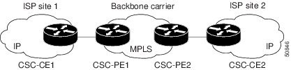
An ISP has two sites: one in California, the other in Maine. Each site is a point of presence (POP). The ISP wants to connect these sites using a VPN service provided by a backbone carrier. Figure 1 illustrates this situation.
Figure 1 Sample BGP/MPLS Backbone Carrier Supporting an ISP
Note
In this example, only the backbone carrier uses MPLS. The customer carrier (ISP) uses only IP. As a result, the backbone carrier must carry all the Internet routes of the customer carrier, which could be as many as 100,000 routes. This poses a scalability problem for the backbone carrier. To solve the scalability problem, the backbone carrier is configured as follows:
•
•
Internal and external routes are differentiated this way:
•
•
The number of internal routes is much lower than the number of external routes. Restricting the routes between the CE routers of the customer carrier and the PE routers of the backbone carrier significantly reduces the number of routes that the PE router needs to maintain.
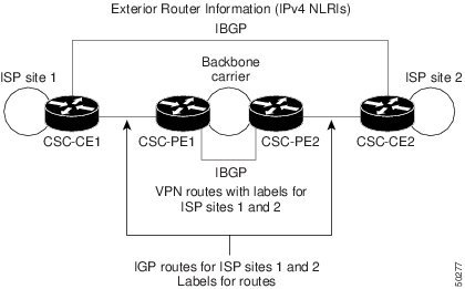
Because the PE routers do not have to carry external routes in the VRF routing table, they can use the incoming label in the packet to forward the customer carrier Internet traffic. Adding MPLS to the routers provides a consistent method of transporting packets from the customer carrier to the backbone carrier. MPLS allows the exchange of an MPLS label between the PE and the CE routers for every internal customer carrier route. The routers in the customer carrier have all the external routes either through internal Border Gateway Protocol (iBGP) or route redistribution to provide Internet connectivity. Figure 2 shows how information is exchanged when the network is configured in this manner.
Figure 2 Backbone Carrier Exchanging Routing Information with a Customer Carrier Who Is an ISP
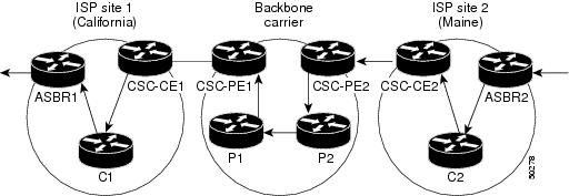
In Figure 3, routes are created between the backbone carrier and the customer carrier sites. ASBR2 receives an Internet route that originated outside the network. All routers in the ISP sites have all the external routes through IBGP connections among them.
Figure 3 Establishing a Route Between a Backbone Carrier and a Customer Carrier Who Is an ISP
Table 2 describes the process of establishing the route, which can be divided into two distinct steps:
•
•
Customer Carrier Is a BGP/MPLS VPN Service Provider
When a backbone carrier and the customer carrier both provide BGP/MPLS VPN services, the method of transporting data is different from when a customer carrier provides only ISP services. The following list highlights those differences:
•
•
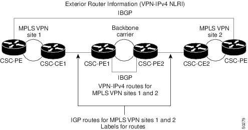
Figure 4 shows how information is exchanged when MPLS VPN services reside on all customer carrier sites and on the backbone carrier.
Figure 4 Backbone Carrier Exchanging Information with a Customer Carrier Who Is an MPLS VPN Service Provider
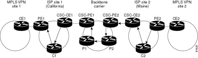
In the example shown in Figure 5, routes are created between the backbone carrier and the customer carrier sites.
Figure 5 Establishing a Route Between a Backbone Carrier and a Customer Carrier Who Is an MPLS VPN Service Provider
Table 3 describes the process of establishing the route.
How to Configure MPLS VPN CSC with LDP and IGP
This section contains the following procedures:
•
•
•
Configuring the Backbone Carrier Core
Configuring the backbone carrier core requires configuring connectivity and routing functions for the CSC core and the CSC-PE routers.
Configuring and verifying the CSC core (backbone carrier) involves the following tasks:
•
•
•
Prerequisites
Before you configure a backbone carrier core, configure the following on the CSC core routers:
•
•
Verifying IP Connectivity and LDP Configuration in the CSC Core
Perform this task to verify IP connectivity and LDP configuration in the CSC core. For a configuration example for this task, see the "Verifying IP Connectivity and LDP Configuration in the CSC Core" section.
SUMMARY STEPS
1.
2.
3.
4.
5.
6.
7.
8.
9.
10.
DETAILED STEPS
Troubleshooting Tips
You can use the ping and trace commands to verify complete MPLS connectivity in the core. You also get useful troubleshooting information from the additional show commands.
Configuring VRFs for CSC-PE Routers
Perform this task to configure VPN routing and forwarding (VRF) instances for the backbone carrier edge (CSC-PE) routers.
SUMMARY STEPS
1.
2.
3.
4.
5.
6.
7.
8.
9.
10.
DETAILED STEPS
Troubleshooting Tips
Enter a show ip vrf detail command and make sure the MPLS VPN is up and associated with the right interfaces.
Configuring Multiprotocol BGP for VPN Connectivity in the Backbone Carrier
Perform this task to configure multiprotocol BGP (MP-BGP) for VPN connectivity in the backbone carrier.
SUMMARY STEPS
1.
2.
3.
4.
5.
6.
7.
8.
9.
10.
DETAILED STEPS
Troubleshooting Tips
You can enter a show ip bgp neighbor command to verify that the neighbors are up and running. If this command generates an error message, enter a debug ip bgp x.x.x.x events command, where x.x.x.x is the IP address of the neighbor.
Configuring the CSC-PE and CSC-CE Routers
To enable the CSC-PE and CSC-CE routers to distribute routes and MPLS labels, perform the following tasks:
•
•
Prerequisites
Before you configure the CSC-PE and CSC-CE routers, you must configure an IGP on the CSC-PE and CSC-CE routers. A routing protocol is required between the PE and CE routers that connect the backbone carrier to the customer carrier. The routing protocol enables the customer carrier to exchange IGP routing information with the backbone carrier. Use the same routing protocol that the customer carrier uses. You can choose RIP, OSPF, or static routing as the routing protocol. BGP is not supported. For the configuration steps, see Configuring MPLS Layer 3 VPNs.
Configuring LDP on the CSC-PE and CSC-CE Routers
MPLS LDP is required between the PE and CE routers that connect the backbone carrier to the customer carrier. You can configure LDP as the default label distribution protocol for the entire router or just for the PE-to-CE interface for VRF.
SUMMARY STEPS
1.
2.
3.
4.
5.
6.
DETAILED STEPS
Enabling MPLS Encapsulation on the CSC-PE and CSC-CE Routers
Every packet that crosses the backbone carrier must be encapsulated, so that the packet includes MPLS labels. You can enable MPLS encapsulation for the entire router or just on the interface of the PE or CE router. To enable the encapsulation of packets, perform the following task.
SUMMARY STEPS
1.
2.
3.
4.
5.
6.
DETAILED STEPS
Verifying the Carrier Supporting Carrier Configuration
The following commands verify the status of LDP sessions that were configured between the backbone carrier and customer carrier. Now the customer carrier ISP sites appear as a VPN customer to the backbone carrier.
SUMMARY STEPS
1.
2.
DETAILED STEPS
Step 1
Use this command to show that the LDP sessions are in VRF VPN1 of the PE router of the backbone carrier, for example:
Router# show mpls ldp discovery vrf vpn1Local LDP Identifier:10.0.0.0:0Discovery Sources:Interfaces:Ethernet1/0 (ldp): xmit/recvLDP Id: 10.0.0.1:0POS6/0 (ldp): xmitStep 2
Use this command to list all LDP sessions in a router, for example:
Router# show mpls ldp discovery allLocal LDP Identifier:10.10.10.10:0Discovery Sources:Interfaces:Ethernet1/5 (ldp): xmit/recvLDP Id: 10.5.5.5:0VRF vpn1: Local LDP Identifier:10.0.0.1:0Discovery Sources:Interfaces:Ethernet1/0 (ldp): xmit/recvLDP Id: 10.0.0.1:0POS6/0 (ldp): xmitThe Local LDP Identifier field shows the LDP identifier for the local label switching router for this session. The Interfaces field displays the interfaces engaging in LDP discovery activity:
•
•
Configuration Examples for MPLS VPN CSC with LDP and IGP
This section provides the following configuration examples:
•
•
•
•
MPLS VPN CSC Network with a Customer Who Is an ISP: Example
Figure 6 shows a carrier supporting carrier network configuration where the customer carrier is an ISP. The customer carrier has two sites, each of which is a POP. The customer carrier connects these sites using a VPN service provided by the backbone carrier. The backbone carrier uses MPLS. The ISP sites use IP. To enable packet transfer between the ISP sites and the backbone carrier, the CE routers that connect the ISPs to the backbone carrier run MPLS.
Figure 6 Carrier Supporting Carrier Network with a Customer Carrier Who Is an ISP
The following examples show the configuration of each router in the carrier supporting carrier network. OSPF is used to connect the customer carrier to the backbone carrier.
CSC-CE1 Configuration
mpls label protocol ldp!interface Loopback0ip address 10.14.14.14 255.255.255.255no ip directed-broadcastno ip route-cacheno ip mroute-cache!interface ATM1/0no ip addressno ip directed-broadcastno ip mroute-cacheatm clock INTERNALatm sonet stm-1no atm enable-ilmi-trapno atm ilmi-keepalive!interface ATM1/0.1 point-to-pointip address 10.0.0.2 255.0.0.0no ip directed-broadcastatm pvc 101 0 51 aal5snapno atm enable-ilmi-trapmpls label protocol ldpmpls ip!interface ATM2/0no ip addressno ip directed-broadcastno ip mroute-cacheatm clock INTERNALatm sonet stm-1no atm enable-ilmi-trapno atm ilmi-keepalive!interface ATM2/0.1 point-to-pointip address 10.0.0.2 255.0.0.0no ip directed-broadcastatm pvc 100 0 50 aal5snapno atm enable-ilmi-trapmpls label protocol ldpmpls ip!router ospf 200log-adjacency-changesredistribute connected subnetsnetwork 10.14.14.14 0.0.0.0 area 200network 10.15.0.0 0.255.255.255 area 200network 10.16.0.0 0.255.255.255 area 200CSC-PE1 Configuration
ip cef distributed!ip vrf vpn1rd 100:0route-target export 100:0route-target import 100:0mpls label protocol ldpno mpls aggregate-statistics!interface Loopback0ip address 10.11.11.11 255.255.255.255no ip directed-broadcastno ip route-cacheno ip mroute-cache!interface Loopback100ip vrf forwarding vpn1ip address 10.19.19.19 255.255.255.255no ip directed-broadcast!interface ATM1/1/0no ip addressno ip directed-broadcastno ip route-cache distributedatm clock INTERNALno atm enable-ilmi-trapno atm ilmi-keepalive!interface ATM1/1/0.1ip address 10.0.0.1 255.0.0.0no ip directed-broadcastatm pvc 100 0 50 aal5snapno atm enable-ilmi-trapmpls label protocol ldpmpls ip!interface ATM3/0/0no ip addressno ip directed-broadcastno ip route-cache distributedatm clock INTERNALatm sonet stm-1no atm enable-ilmi-trapno atm ilmi-keepalive!interface ATM3/0/0.1 point-to-pointip vrf forwarding vpn1ip address 10.0.0.1 255.0.0.0no ip directed-broadcastatm pvc 101 0 51 aal5snapno atm enable-ilmi-trapmpls label protocol ldpmpls ip!router ospf 100log-adjacency-changespassive-interface ATM3/0/0.1passive-interface Loopback100network 10.11.11.11 0.0.0.0 area 100network 10.0.0.0 0.255.255.255 area 100!router ospf 200 vrf vpn1log-adjacency-changesredistribute bgp 100 metric-type 1 subnetsnetwork 10.19.19.19 0.0.0.0 area 200network 10.0.0.0 0.255.255.255 area 200!router bgp 100bgp log-neighbor-changestimers bgp 10 30neighbor 10.12.12.12 remote-as 100neighbor 10.12.12.12 update-source Loopback0!address-family ipv4neighbor 10.12.12.12 activateneighbor 10.12.12.12 send-community extendedno synchronizationexit-address-family!address-family vpnv4neighbor 10.12.12.12 activateneighbor 10.12.12.12 send-community extendedexit-address-family!address-family ipv4 vrf vpn1redistribute ospf 200 match internal external 1 external 2no auto-summaryno synchronizationexit-address-familyCSC-PE2 Configuration
ip cef distributed!ip vrf vpn1rd 100:0route-target export 100:0route-target import 100:0mpls label protocol ldpno mpls aggregate-statistics!interface Loopback0ip address 10.12.12.12 255.255.255.255no ip directed-broadcastno ip route-cacheno ip mroute-cache!interface Loopback100ip vrf forwarding vpn1ip address 10.20.20.20 255.255.255.255no ip directed-broadcast!interface ATM0/1/0no ip addressno ip directed-broadcastno ip route-cache distributedno ip mroute-cacheatm clock INTERNALatm sonet stm-1no atm enable-ilmi-trapno atm ilmi-keepalive!interface ATM0/1/0.1 point-to-pointip address 10.0.0.2 255.0.0.0no ip directed-broadcastatm pvc 100 0 50 aal5snapno atm enable-ilmi-trapmpls label protocol ldpmpls ip!interface ATM3/0/0no ip addressno ip directed-broadcastno ip route-cache distributedno ip mroute-cacheatm clock INTERNALatm sonet stm-1no atm enable-ilmi-trapno atm ilmi-keepalive!interface ATM3/0/0.1 point-to-pointip vrf forwarding vpn1ip address 10.0.0.1 255.0.0.0no ip directed-broadcastatm pvc 100 0 50 aal5snapno atm enable-ilmi-trapmpls label protocol ldpmpls ip!router ospf 100log-adjacency-changespassive-interface ATM3/0/0.1passive-interface Loopback100network 10.12.12.12 0.0.0.0 area 100network 10.0.0.0 0.255.255.255 area 100!router ospf 200 vrf vpn1log-adjacency-changesredistribute bgp 100 metric-type 1 subnetsnetwork 10.20.20.20 0.0.0.0 area 200network 10.0.0.0 0.255.255.255 area 200!router bgp 100bgp log-neighbor-changestimers bgp 10 30neighbor 10.11.11.11 remote-as 100neighbor 10.11.11.11 update-source Loopback0!address-family ipv4neighbor 10.11.11.11 activateneighbor 10.11.11.11 send-community extendedno synchronizationexit-address-family!address-family vpnv4neighbor 10.11.11.11 activateneighbor 10.11.11.11 send-community extendedexit-address-family!address-family ipv4 vrf vpn1redistribute ospf 200 match internal external 1 external 2no auto-summaryno synchronizationexit-address-familyCSC-CE2 Configuration
ip cef!mpls label protocol ldp!interface Loopback0ip address 10.16.16.16 255.255.255.255no ip directed-broadcastno ip route-cacheno ip mroute-cache!interface ATM1/0no ip addressno ip directed-broadcastno ip mroute-cacheatm clock INTERNALatm sonet stm-1no atm enable-ilmi-trapno atm ilmi-keepalive!interface ATM1/0.1 point-to-pointip address 10.0.0.2 255.0.0.0no ip directed-broadcastatm pvc 100 0 50 aal5snapno atm enable-ilmi-trapmpls label protocol ldpmpls ip!interface ATM5/0no ip addressno ip directed-broadcastno ip mroute-cacheatm clock INTERNALatm sonet stm-1no atm enable-ilmi-trapno atm ilmi-keepalive!interface ATM5/0.1 point-to-pointip address 10.0.0.2 255.0.0.0no ip directed-broadcastatm pvc 100 0 50 aal5snapno atm enable-ilmi-trapmpls label protocol ldpmpls ip!router ospf 200log-adjacency-changesredistribute connected subnetsnetwork 10.16.16.16 0.0.0.0 area 200network 10.0.0.0 0.255.255.255 area 200network 10.0.0.0 0.255.255.255 area 200MPLS VPN CSC Network with a Customer Who Is an MPLS VPN Provider: Example
Figure 7 shows a carrier supporting carrier network configuration where the customer carrier is an MPLS VPN provider. The customer carrier has two sites. The backbone carrier and the customer carrier use MPLS. The IBGP sessions exchange the external routing information of the ISP.
Figure 7 Carrier Supporting Carrier Network with a Customer Carrier Who Is an MPLS VPN Provider
The following configuration examples show the configuration of each router in the carrier supporting carrier network. OSPF is the protocol used to connect the customer carrier to the backbone carrier.
CE1 Configuration
ip cef!interface Loopback0ip address 10.17.17.17 255.255.255.255no ip directed-broadcast!interface Ethernet0/1ip address 10.0.0.2 255.0.0.0no ip directed-broadcast!router ospf 300log-adjacency-changesredistribute bgp 300 subnetspassive-interface Ethernet0/1network 10.17.17.17 0.0.0.0 area 300!router bgp 300no synchronizationbgp log-neighbor-changestimers bgp 10 30redistribute connectedredistribute ospf 300 match internal external 1 external 2neighbor 10.0.0.1 remote-as 200neighbor 10.0.0.1 advertisement-interval 5no auto-summaryPE1 Configuration
ip cef!ip vrf vpn2rd 200:1route-target export 200:1route-target import 200:1mpls label protocol ldp!interface Loopback0ip address 10.13.13.13 255.255.255.255no ip directed-broadcastno ip route-cacheno ip mroute-cache!interface ATM1/0no ip addressno ip directed-broadcastno ip mroute-cacheatm clock INTERNALatm sonet stm-1no atm enable-ilmi-trapno atm ilmi-keepalive!interface ATM1/0.1 point-to-pointip address 10.0.0.1 255.0.0.0no ip directed-broadcastatm pvc 100 0 50 aal5snapno atm enable-ilmi-trapmpls label protocol ldpmpls ip!interface Ethernet3/0ip vrf forwarding vpn2ip address 10.0.0.1 255.0.0.0no ip directed-broadcastno ip mroute-cache!router ospf 200log-adjacency-changesredistribute connected subnetspassive-interface Ethernet3/0network 10.13.13.13 0.0.0.0 area 200network 10.0.0.0 0.255.255.255 area 200!router bgp 200no bgp default ipv4-unicastbgp log-neighbor-changestimers bgp 10 30neighbor 10.15.15.15 remote-as 200neighbor 10.15.15.15 update-source Loopback0!address-family ipv4neighbor 10.15.15.15 activateneighbor 10.15.15.15 send-community extendedno synchronizationexit-address-family!address-family vpnv4neighbor 10.15.15.15 activateneighbor 10.15.15.15 send-community extendedexit-address-family!address-family ipv4 vrf vpn2neighbor 10.0.0.2 remote-as 300neighbor 10.0.0.2 activateneighbor 10.0.0.2 as-overrideneighbor 10.0.0.2 advertisement-interval 5no auto-summaryno synchronizationexit-address-familyCSC-CE1 Configuration
mpls label protocol ldp!interface Loopback0ip address 10.14.14.14 255.255.255.255no ip directed-broadcastno ip route-cacheno ip mroute-cache!interface ATM1/0no ip addressno ip directed-broadcastno ip mroute-cacheatm clock INTERNALatm sonet stm-1no atm enable-ilmi-trapno atm ilmi-keepalive!interface ATM1/0.1 point-to-pointip address 10.0.0.2 255.0.0.0no ip directed-broadcastatm pvc 101 0 51 aal5snapno atm enable-ilmi-trapmpls label protocol ldpmpls ip!interface ATM2/0no ip addressno ip directed-broadcastno ip mroute-cacheatm clock INTERNALatm sonet stm-1no atm enable-ilmi-trapno atm ilmi-keepalive!interface ATM2/0.1 point-to-pointip address 10.0.0.2 255.0.0.0no ip directed-broadcastatm pvc 100 0 50 aal5snapno atm enable-ilmi-trapmpls label protocol ldpmpls ip!router ospf 200log-adjacency-changesredistribute connected subnetsnetwork 10.14.14.14 0.0.0.0 area 200network 10.0.0.0 0.255.255.255 area 200network 10.0.0.0 0.255.255.255 area 200CSC-PE1 Configuration
ip cef distributed!ip vrf vpn1rd 100:0route-target export 100:0route-target import 100:0mpls label protocol ldpno mpls aggregate-statistics!interface Loopback0ip address 11.11.11.11 255.255.255.255no ip directed-broadcastno ip route-cacheno ip mroute-cache!interface Loopback100ip vrf forwarding vpn1ip address 10.19.19.19 255.255.255.255no ip directed-broadcast!interface ATM1/1/0no ip addressno ip directed-broadcastno ip route-cache distributedatm clock INTERNALno atm enable-ilmi-trapno atm ilmi-keepalive!interface ATM1/1/0.1 point-to-pointip address 10.0.0.1 255.0.0.0no ip directed-broadcastatm pvc 100 0 50 aal5snapno atm enable-ilmi-trapmpls label protocol ldpmpls ip!interface ATM3/0/0no ip addressno ip directed-broadcastno ip route-cache distributedatm clock INTERNALatm sonet stm-1no atm enable-ilmi-trapno atm ilmi-keepalive!interface ATM3/0/0.1 point-to-pointip vrf forwarding vpn1ip address 10.0.0.1 255.0.0.0no ip directed-broadcastatm pvc 101 0 51 aal5snapno atm enable-ilmi-trapmpls label protocol ldpmpls ip!router ospf 100log-adjacency-changespassive-interface ATM3/0/0.1passive-interface Loopback100network 10.11.11.11 0.0.0.0 area 100network 10.0.0.0 0.255.255.255 area 100!router ospf 200 vrf vpn1log-adjacency-changesredistribute bgp 100 metric-type 1 subnetsnetwork 10.19.19.19 0.0.0.0 area 200network 10.0.0.0 0.255.255.255 area 200!router bgp 100bgp log-neighbor-changestimers bgp 10 30neighbor 10.12.12.12 remote-as 100neighbor 10.12.12.12 update-source Loopback0!address-family ipv4neighbor 10.12.12.12 activateneighbor 10.12.12.12 send-community extendedno synchronizationexit-address-family!address-family vpnv4neighbor 10.12.12.12 activateneighbor 10.12.12.12 send-community extendedexit-address-family!address-family ipv4 vrf vpn1redistribute ospf 200 match internal external 1 external 2no auto-summaryno synchronizationexit-address-familyCSC-PE2 Configuration
ip cef distributed!ip vrf vpn1rd 100:0route-target export 100:0route-target import 100:0mpls label protocol ldpno mpls aggregate-statistics!interface Loopback0ip address 10.12.12.12 255.255.255.255no ip directed-broadcastno ip route-cacheno ip mroute-cache!interface Loopback100ip vrf forwarding vpn1ip address 10.20.20.20 255.255.255.255no ip directed-broadcast!interface ATM0/1/0no ip addressno ip directed-broadcastno ip route-cache distributedno ip mroute-cacheatm clock INTERNALatm sonet stm-1no atm enable-ilmi-trapno atm ilmi-keepalive!interface ATM0/1/0.1 point-to-pointip address 10.0.0.2 255.0.0.0no ip directed-broadcastatm pvc 100 0 50 aal5snapno atm enable-ilmi-trapmpls label protocol ldpmpls ip!interface ATM3/0/0no ip addressno ip directed-broadcastno ip route-cache distributedno ip mroute-cacheatm clock INTERNALatm sonet stm-1no atm enable-ilmi-trapno atm ilmi-keepalive!interface ATM3/0/0.1 point-to-pointip vrf forwarding vpn1ip address 10.0.0.1 255.0.0.0no ip directed-broadcastatm pvc 100 0 50 aal5snapno atm enable-ilmi-trapmpls label protocol ldpmpls ip!router ospf 100log-adjacency-changespassive-interface ATM3/0/0.1passive-interface Loopback100network 10.12.12.12 0.0.0.0 area 100network 10.0.0.0 0.255.255.255 area 100!router ospf 200 vrf vpn1log-adjacency-changesredistribute bgp 100 metric-type 1 subnetsnetwork 10.20.20.20 0.0.0.0 area 200network 10.0.0.0 0.255.255.255 area 200!router bgp 100bgp log-neighbor-changestimers bgp 10 30neighbor 10.11.11.11 remote-as 100neighbor 10.11.11.11 update-source Loopback0!address-family ipv4neighbor 10.11.11.11 activateneighbor 10.11.11.11 send-community extendedno synchronizationexit-address-family!address-family vpnv4neighbor 10.11.11.11 activateneighbor 10.11.11.11 send-community extendedexit-address-family!address-family ipv4 vrf vpn1redistribute ospf 200 match internal external 1 external 2no auto-summaryno synchronizationexit-address-familyCSC-CE2 Configuration
ip cef!mpls label protocol ldp!interface Loopback0ip address 10.16.16.16 255.255.255.255no ip directed-broadcastno ip route-cacheno ip mroute-cache!interface ATM1/0no ip addressno ip directed-broadcastno ip mroute-cacheatm clock INTERNALatm sonet stm-1no atm enable-ilmi-trapno atm ilmi-keepalive!interface ATM1/0.1 point-to-pointip address 10.0.0.2 255.0.0.0no ip directed-broadcastatm pvc 100 0 50 aal5snapno atm enable-ilmi-trapmpls label protocol ldpmpls ip!interface ATM5/0no ip addressno ip directed-broadcastno ip mroute-cacheatm clock INTERNALatm sonet stm-1no atm enable-ilmi-trapno atm ilmi-keepalive!interface ATM5/0.1 point-to-pointip address 10.0.0.2 255.0.0.0no ip directed-broadcastatm pvc 100 0 50 aal5snapno atm enable-ilmi-trapmpls label protocol ldpmpls ip!router ospf 200log-adjacency-changesredistribute connected subnetsnetwork 10.16.16.16 0.0.0.0 area 200network 10.0.0.0 0.255.255.255 area 200network 10.0.0.0 0.255.255.255 area 200PE2 Configuration
ip cefip cef accounting non-recursive!ip vrf vpn2rd 200:1route-target export 200:1route-target import 200:1mpls label protocol ldp!interface Loopback0ip address 10.15.15.15 255.255.255.255no ip directed-broadcast!interface Ethernet3/0ip vrf forwarding vpn2ip address 10.0.0.1 255.0.0.0no ip directed-broadcast!interface ATM5/0no ip addressno ip directed-broadcastatm clock INTERNALatm sonet stm-1no atm enable-ilmi-trapno atm ilmi-keepalive!interface ATM5/0.1 point-to-pointip address 10.0.0.1 255.0.0.0no ip directed-broadcastatm pvc 100 0 50 aal5snapno atm enable-ilmi-trapmpls label protocol ldpmpls ip!router ospf 200log-adjacency-changesredistribute connected subnetspassive-interface Ethernet3/0network 10.15.15.15 0.0.0.0 area 200network 10.0.0.0 0.255.255.255 area 200!router bgp 200no bgp default ipv4-unicastbgp log-neighbor-changestimers bgp 10 30neighbor 10.13.13.13 remote-as 200neighbor 10.13.13.13 update-source Loopback0!address-family ipv4neighbor 10.13.13.13 activateneighbor 10.13.13.13 send-community extendedno synchronizationexit-address-family!address-family vpnv4neighbor 10.13.13.13 activateneighbor 10.13.13.13 send-community extendedexit-address-family!address-family ipv4 vrf vpn2neighbor 10.0.0.2 remote-as 300neighbor 10.0.0.2 activateneighbor 10.0.0.2 as-overrideneighbor 10.0.0.2 advertisement-interval 5no auto-summaryno synchronizationexit-address-familyCE2 Configuration
ip cef!interface Loopback0ip address 10.18.18.18 255.255.255.255no ip directed-broadcast!interface Ethernet0/1ip address 10.0.0.2 255.0.0.0no ip directed-broadcast!router ospf 300log-adjacency-changesredistribute bgp 300 subnetspassive-interface Ethernet0/1network 10.18.18.18 0.0.0.0 area 300!router bgp 300no synchronizationbgp log-neighbor-changestimers bgp 10 30redistribute connectedredistribute ospf 300 match internal external 1 external 2neighbor 10.0.0.1 remote-as 200neighbor 10.0.0.1 advertisement-interval 5no auto-summaryMPLS VPN CSC Network That Contains Route Reflectors: Example
Figure 8 shows a carrier supporting carrier network configuration that contains route reflectors. The customer carrier has two sites.
Figure 8 Carrier Supporting Carrier Network that Contains Route Reflectors
Note
The following configuration examples show the configuration of each router in the carrier supporting carrier network. Note the following:
•
•
–
–
Backbone Carrier Configuration
Route Reflector 1 (72K-37-1) Configuration
interface Loopback0ip address 10.13.13.13 255.255.255.255no ip directed-broadcastno ip route-cacheno ip mroute-cache!interface ATM1/0no ip addressno ip directed-broadcastatm clock INTERNALno atm enable-ilmi-trapno atm ilmi-keepalive!interface ATM1/0.1 mplsip address 10.0.0.2 255.0.0.0no ip directed-broadcastno atm enable-ilmi-trapmpls label protocol ldpmpls atm vpi 2-5mpls ip!interface ATM1/1no ip addressno ip directed-broadcastatm clock INTERNALno atm enable-ilmi-trapno atm ilmi-keepalive!interface ATM1/1.1 mplsip address 10.0.0.1 255.0.0.0no ip directed-broadcastno atm enable-ilmi-trapmpls label protocol ldpmpls atm vpi 2-5mpls ip!router ospf 100auto-cost reference-bandwidth 10000network 10.0.0.0 0.255.255.255 area 100network 10.1.0.0 0.255.255.255 area 100network 10.2.0.0 0.255.255.255 area 100!router bgp 100no synchronizationno bgp default ipv4-unicastbgp cluster-id 1redistribute staticneighbor 10.15.15.15 remote-as 100neighbor 10.15.15.15 update-source Loopback0neighbor 10.16.16.16 remote-as 100neighbor 10.16.16.16 update-source Loopback0!address-family ipv4 vrf vpn1no auto-summaryno synchronizationexit-address-family!address-family vpnv4neighbor 10.15.15.15 activateneighbor 10.15.15.15 route-reflector-clientneighbor 10.15.15.15 send-community extendedneighbor 10.16.16.16 activateneighbor 10.16.16.16 route-reflector-clientneighbor 10.16.16.16 send-community extendedbgp scan-time import 5exit-address-familyRoute Reflector 2 (72K-38-1) Configuration
interface Loopback0ip address 10.14.14.14 255.255.255.255no ip directed-broadcastno ip mroute-cache!interface ATM1/0no ip addressno ip directed-broadcastatm clock INTERNALno atm enable-ilmi-trapno atm ilmi-keepalive!interface ATM1/0.1 mplsip address 10.0.0.1 255.0.0.0no ip directed-broadcastno atm enable-ilmi-trapmpls label protocol ldpmpls atm vpi 2-5mpls ip!interface ATM1/1no ip addressno ip directed-broadcastatm clock INTERNALno atm enable-ilmi-trapno atm ilmi-keepalive!interface ATM1/1.1 mplsip address 10.0.0.2 255.0.0.0no ip directed-broadcastno atm enable-ilmi-trapmpls label protocol ldpmpls atm vpi 2-5mpls ip!router ospf 100auto-cost reference-bandwidth 10000network 10.0.0.0 0.255.255.255 area 100network 10.1.0 0.255.255.255 area 100network 10.2.0.0 0.255.255.255 area 100!router bgp 100no synchronizationno bgp default ipv4-unicastbgp cluster-id 1redistribute staticneighbor 10.15.15.15 remote-as 100neighbor 10.15.15.15 update-source Loopback0neighbor 10.16.16.16 remote-as 100neighbor 10.16.16.16 update-source Loopback0!address-family ipv4 vrf vpn1no auto-summaryno synchronizationexit-address-family!address-family vpnv4neighbor 10.15.15.15 activateneighbor 10.15.15.15 route-reflector-clientneighbor 10.15.15.15 send-community extendedneighbor 10.16.16.16 activateneighbor 10.16.16.16 route-reflector-clientneighbor 10.16.16.16 send-community extendedbgp scan-time import 5exit-address-familyCSC-PE1 (75K-37-3) Configuration
ip cef distributed!ip vrf vpn1rd 100:1route-target export 100:1route-target import 100:1!interface Loopback0ip address 10.15.15.15 255.255.255.255no ip directed-broadcast!interface Loopback1ip vrf forwarding vpn1ip address 10.18.18.18 255.255.255.255no ip directed-broadcast!interface Ethernet0/0/1ip vrf forwarding vpn1ip address 10.0.0.2 255.0.0.0no ip directed-broadcastno ip route-cache distributedmpls label protocol ldpmpls ip!interface ATM1/1/0no ip addressno ip directed-broadcastno ip route-cache distributedatm clock INTERNALatm sonet stm-1no atm enable-ilmi-trapno atm ilmi-keepalive!interface ATM1/1/0.1 mplsip address 10.0.0.1 255.0.0.0no ip directed-broadcastno atm enable-ilmi-trapmpls label protocol ldpmpls atm vpi 2-5mpls ip!interface ATM3/0/0no ip addressno ip directed-broadcastno ip route-cache distributedatm clock INTERNALatm sonet stm-1no atm enable-ilmi-trapno atm ilmi-keepalive!interface ATM3/0/0.1 point-to-pointip vrf forwarding vpn1ip address 10.0.0.2 255.0.0.0no ip directed-broadcastatm pvc 100 6 32 aal5snapno atm enable-ilmi-trapmpls label protocol ldpmpls ip!interface ATM3/1/0no ip addressno ip directed-broadcastno ip route-cache distributedatm clock INTERNALatm sonet stm-1no atm enable-ilmi-trapno atm ilmi-keepalive!interface ATM3/1/0.1 mplsip address 10.0.0.1 255.0.0.0no ip directed-broadcastno atm enable-ilmi-trapmpls label protocol ldpmpls atm vpi 2-5mpls ip!router ospf 100auto-cost reference-bandwidth 10000network 10.0.0.0 0.255.255.255 area 100network 10.1.0.0 0.255.255.255 area 100network 10.2.0.0 0.255.255.255 area 100network 10.3.0.0 0.255.255.255 area 100network 10.4.0.0 0.255.255.255 area 100!router ospf 1 vrf vpn1redistribute bgp 100 metric-type 1 subnetsnetwork 10.0.0.0 0.255.255.255 area 101network 10.0.0.0 0.255.255.255 area 101network 10.0.0.0 0.255.255.255 area 101network 10.0.0.0 0.255.255.255 area 101!router bgp 100no bgp default ipv4-unicastbgp log-neighbor-changesneighbor 10.13.13.13 remote-as 100neighbor 10.13.13.13 update-source Loopback0neighbor 10.14.14.14 remote-as 100neighbor 10.14.14.14 update-source Loopback0!address-family ipv4redistribute staticno synchronizationexit-address-family!address-family vpnv4neighbor 10.13.13.13 activateneighbor 10.13.13.13 send-community extendedneighbor 10.14.14.14 activateneighbor 10.14.14.14 send-community extendedexit-address-family!address-family ipv4 vrf vpn1redistribute ospf 1 match internal external 1 external 2no auto-summaryno synchronizationexit-address-familyCSC-PE2 (75K-38-3) Configuration
ip cef distributed!ip vrf vpn1rd 100:1route-target export 100:1route-target import 100:1!interface Loopback0ip address 10.16.16.16 255.255.255.255no ip directed-broadcast!interface Loopback1ip vrf forwarding vpn1ip address 10.20.20.20 255.255.255.255no ip directed-broadcast!interface ATM0/1/0no ip addressno ip directed-broadcastno ip route-cache distributedatm clock INTERNALatm sonet stm-1no atm enable-ilmi-trapno atm ilmi-keepalive!interface ATM0/1/0.1 mplsip address 10.0.0.2 255.0.0.0no ip directed-broadcastno atm enable-ilmi-trapmpls label protocol ldpmpls atm vpi 2-5mpls ip!interface ATM2/1/0no ip addressno ip directed-broadcastno ip route-cache distributedatm clock INTERNALatm sonet stm-1no atm enable-ilmi-trapno atm ilmi-keepalive!interface ATM2/1/0.1 mplsip address 10.0.0.2 255.0.0.0no ip directed-broadcastno atm enable-ilmi-trapmpls label protocol ldpmpls atm vpi 2-5mpls ip!interface ATM3/0/0no ip addressno ip directed-broadcastno ip route-cache distributedatm clock INTERNALatm sonet stm-1no atm enable-ilmi-trapno atm ilmi-keepalive!interface ATM3/0/0.1 point-to-pointip vrf forwarding vpn1ip address 10.0.0.1 255.0.0.0no ip directed-broadcastatm pvc 100 6 32 aal5snapno atm enable-ilmi-trapmpls label protocol ldpmpls ip!interface ATM3/1/0no ip addressno ip directed-broadcastno ip route-cache distributedatm clock INTERNALatm sonet stm-1no atm enable-ilmi-trapno atm ilmi-keepalive!interface ATM3/1/0.1 point-to-pointip vrf forwarding vpn1ip address 10.0.0.1 255.0.0.0no ip directed-broadcastatm pvc 101 6 33 aal5snapno atm enable-ilmi-trapmpls label protocol ldpmpls ip!router ospf 100auto-cost reference-bandwidth 10000network 10.0.0.0 0.255.255.255 area 100network 10.0.0.0 0.255.255.255 area 100network 10.0.0.0 0.255.255.255 area 100network 10.0.0.0 0.255.255.255 area 100network 10.0.0.0 0.255.255.255 area 100!router ospf 1 vrf vpn1redistribute bgp 100 metric-type 1 subnetsnetwork 10.0.0.0 0.255.255.255 area 101network 10.0.0.0 0.255.255.255 area 101network 10.0.0.0 0.255.255.255 area 101network 10.0.0.0 0.255.255.255 area 101!router bgp 100no bgp default ipv4-unicastbgp log-neighbor-changesneighbor 10.13.13.13 remote-as 100neighbor 10.13.13.13 update-source Loopback0neighbor 10.14.14.14 remote-as 100neighbor 10.14.14.14 update-source Loopback0!address-family ipv4redistribute staticno synchronizationexit-address-family!address-family vpnv4neighbor 10.13.13.13 activateneighbor 10.13.13.13 send-community extendedneighbor 10.14.14.14 activateneighbor 10.14.14.14 send-community extendedexit-address-family!address-family ipv4 vrf vpn1redistribute ospf 1 match internal external 1 external 2no auto-summaryno synchronizationexit-address-familyCustomer Carrier Site 1 Configuration
PE1 (72K-36-8) Configuration
ip cef!ip vrf vpn2rd 200:1route-target export 200:1route-target import 200:1no mpls ip propagate-ttl!interface Loopback0ip address 10.25.25.25 255.255.255.255no ip directed-broadcastno ip route-cacheno ip mroute-cache!interface ATM1/0no ip addressno ip directed-broadcastno ip mroute-cacheatm clock INTERNALno atm ilmi-keepalive!interface ATM1/0.1 point-to-pointip address 10.0.0.2 255.0.0.0no ip directed-broadcastatm pvc 100 0 50 aal5snapmpls label protocol ldpmpls ip!interface Ethernet3/0ip vrf forwarding vpn2ip address 10.0.0.1 255.0.0.0no ip directed-broadcastno ip mroute-cache!interface Ethernet3/1ip address 10.0.0.1 255.0.0.0no ip directed-broadcastno ip mroute-cachempls label protocol ldpmpls ip!interface Ethernet3/2ip address 10.0.0.2 255.0.0.0no ip directed-broadcastno ip mroute-cachempls label protocol ldpmpls ip!router ospf 1network 10.0.0.0 0.255.255.255 area 101network 10.0.0.0 0.255.255.255 area 101network 10.0.0.0 0.255.255.255 area 101network 10.0.0.0 0.255.255.255 area 101!router bgp 200neighbor 10.22.22.22 remote-as 200neighbor 10.22.22.22 update-source Loopback0neighbor 10.23.23.23 remote-as 200neighbor 10.23.23.23 update-source Loopback0!address-family ipv4 vrf vpn2redistribute connectedneighbor 10.0.0.2 remote-as 300neighbor 10.0.0.2 activateneighbor 10.0.0.2 as-overrideno auto-summaryno synchronizationexit-address-family!address-family vpnv4neighbor 10.22.22.22 activateneighbor 10.22.22.22 send-community extendedneighbor 10.23.23.23 activateneighbor 10.23.23.23 send-community extendedexit-address-familyCSC-CE1 (72K-36-9) Configuration
ip cefno ip domain-lookup!interface Loopback0ip address 10.11.11.11 255.255.255.255no ip directed-broadcastno ip route-cacheno ip mroute-cache!interface ATM1/0no ip addressno ip directed-broadcastno ip mroute-cacheatm clock INTERNALno atm ilmi-keepalive!interface ATM1/0.1 point-to-pointip address 10.0.0.1 255.0.0.0no ip directed-broadcastatm pvc 100 6 32 aal5snapmpls label protocol ldpmpls ip!interface ATM2/0no ip addressno ip directed-broadcastno ip mroute-cacheatm clock INTERNALno atm ilmi-keepalive!interface ATM2/0.1 point-to-pointip address 10.0.0.1 255.0.0.0no ip directed-broadcastatm pvc 100 0 50 aal5snapmpls label protocol ldpmpls ip!interface Ethernet3/0ip address 10.0.0.2 255.0.0.0no ip directed-broadcastno ip mroute-cachempls label protocol ldpmpls ip!interface Ethernet3/1ip address 10.0.0.1 255.0.0.0no ip directed-broadcastno ip mroute-cachempls label protocol ldpmpls ip!router ospf 1network 10.0.0.0 0.255.255.255 area 101network 10.0.0.0 0.255.255.255 area 101network 10.0.0.0 0.255.255.255 area 101network 10.0.0.0 0.255.255.255 area 101network 10.0.0.0 0.255.255.255 area 101PE2 (72K-36-7) Configuration
ip cef!ip vrf vpn2rd 200:1route-target export 200:1route-target import 200:1no mpls ip propagate-ttl!interface Loopback0ip address 10.24.24.24 255.255.255.255no ip directed-broadcastno ip route-cacheno ip mroute-cache!interface Ethernet3/0ip address 10.0.0.1 255.0.0.0no ip directed-broadcastno ip mroute-cachempls label protocol ldpmpls ip!interface Ethernet3/1ip vrf forwarding vpn2ip address 10.0.0.1 255.0.0.0no ip directed-broadcastno ip mroute-cache!interface Ethernet3/2ip address 10.0.0.2 255.0.0.0no ip directed-broadcastno ip mroute-cachempls label protocol ldpmpls ip!interface Ethernet3/3ip address 10.0.0.2 255.0.0.0no ip directed-broadcastno ip mroute-cachempls label protocol ldpmpls ip!router ospf 1network 10.0.0.0 0.255.255.255 area 101network 10.0.0.0 0.255.255.255 area 101network 10.0.0.0 0.255.255.255 area 101network 10.0.0.0 0.255.255.255 area 101!router bgp 200neighbor 10.22.22.22 remote-as 200neighbor 10.22.22.22 update-source Loopback0neighbor 10.23.23.23 remote-as 200neighbor 10.23.23.23 update-source Loopback0!address-family ipv4 vrf vpn2neighbor 10.0.0.2 remote-as 300neighbor 10.0.0.2 activateneighbor 10.0.0.2 as-overrideno auto-summaryno synchronizationexit-address-family!address-family vpnv4neighbor 10.22.22.22 activateneighbor 10.22.22.22 send-community extendedneighbor 10.23.23.23 activateneighbor 10.23.23.23 send-community extendedexit-address-familyRoute Reflector 3 (36K-38-4) Configuration
ip cef!interface Loopback0ip address 10.23.23.23 255.255.255.255!interface Ethernet1/1ip address 10.0.0.1 255.0.0.0mpls label protocol ldpmpls ip!interface Ethernet1/2ip address 10.0.0.1 255.0.0.0mpls label protocol ldpmpls ip!interface ATM3/0no ip addressno ip mroute-cacheatm clock INTERNALno atm scrambling cell-payloadno atm ilmi-keepalive!interface ATM3/0.1 point-to-pointip address 10.0.0.2 255.0.0.0atm pvc 100 0 55 aal5snapmpls label protocol ldpmpls ip!router ospf 1log-adjacency-changesnetwork 10.0.0.0 0.255.255.255 area 101network 10.1.0.0 0.255.255.255 area 101network 10.2.0.0 0.255.255.255 area 101network 10.3.0.0 0.255.255.255 area 101!router bgp 200no synchronizationno bgp default ipv4-unicastbgp cluster-id 2redistribute staticneighbor 10.21.21.21 remote-as 200neighbor 10.21.21.21 update-source Loopback0neighbor 10.24.24.24 remote-as 200neighbor 10.24.24.24 update-source Loopback0neighbor 10.25.25.25 remote-as 200neighbor 10.25.25.25 update-source Loopback0!address-family ipv4 vrf vpn2no auto-summaryno synchronizationexit-address-family!address-family vpnv4neighbor 10.21.21.21 activateneighbor 10.21.21.21 route-reflector-clientneighbor 10.21.21.21 send-community extendedneighbor 10.24.24.24 activateneighbor 10.24.24.24 route-reflector-clientneighbor 10.24.24.24 send-community extendedneighbor 10.25.25.25 activateneighbor 10.25.25.25 route-reflector-clientneighbor 10.25.25.25 send-community extendedexit-address-familyCE1 (36K-36-1) Configuration
ip cef!interface Loopback0ip address 10.28.28.28 255.255.255.255no ip directed-broadcast!interface Ethernet0/1ip address 10.0.0.2 255.0.0.0no ip directed-broadcast!interface Ethernet0/2ip address 10.0.0.2 255.0.0.0no ip directed-broadcast!router bgp 300network 10.0.0.0network 10.0.0.0network 10.0.0.0neighbor 10.0.0.1 remote-as 200neighbor 10.0.0.1 remote-as 200Customer Carrier Site 2 Configuration
CSC-CE3 (72K-36-6) Configuration
ip cef!interface Loopback0ip address 10.12.12.12 255.255.255.255no ip directed-broadcastno ip route-cacheno ip mroute-cache!interface ATM1/0no ip addressno ip directed-broadcastno ip mroute-cacheatm clock INTERNALno atm ilmi-keepalive!interface ATM1/0.1 point-to-pointip address 10.0.0.2 255.0.0.0no ip directed-broadcastatm pvc 100 6 32 aal5snapmpls label protocol ldpmpls ip!interface POS2/0ip address 10.0.0.2 255.0.0.0no ip directed-broadcastencapsulation pppmpls label protocol ldpmpls ip!interface ATM5/0no ip addressno ip directed-broadcastno ip mroute-cacheatm clock INTERNALno atm ilmi-keepalive!interface ATM5/0.1 point-to-pointip address 10.0.0.1 255.0.0.0no ip directed-broadcastatm pvc 100 0 40 aal5snapmpls ip!router ospf 1network 10.0.0.0 0.255.255.255 area 101network 10.1.0.0 0.255.255.255 area 101network 10.2.0.0 0.255.255.255 area 101network 10.3.0.0 0.255.255.255 area 101PE3 (72K-36-4) Configuration
ip cef!ip vrf vpn2rd 200:1route-target export 200:1route-target import 200:1!!interface Loopback0ip address 10.21.21.21 255.255.255.255no ip directed-broadcast!interface Ethernet3/0ip vrf forwarding vpn2ip address 10.0.0.1 255.0.0.0no ip directed-broadcast!interface Ethernet3/1ip vrf forwarding vpn2ip address 10.0.0.1 255.0.0.0no ip directed-broadcast!interface Ethernet3/2ip address 10.0.0.1 255.0.0.0no ip directed-broadcastmpls label protocol ldpmpls ip!interface ATM5/0no ip addressno ip directed-broadcastatm clock INTERNALno atm ilmi-keepalive!interface ATM5/0.1 point-to-pointip address 10.0.0.2 255.0.0.0no ip directed-broadcastatm pvc 100 0 40 aal5snapmpls label protocol ldpmpls ip!interface ATM6/0no ip addressno ip directed-broadcastatm clock INTERNALno atm ilmi-keepalive!interface ATM6/0.1 point-to-pointip address 10.0.0.2 255.0.0.0no ip directed-broadcastatm pvc 100 0 20 aal5snapmpls label protocol ldpmpls ip!router ospf 1network 10.0.0.0 0.255.255.255 area 101network 10.1.0.0 0.255.255.255 area 101network 10.2.0.0 0.255.255.255 area 101network 10.3.0.0 0.255.255.255 area 101!router bgp 200neighbor 10.22.22.22 remote-as 200neighbor 10.22.22.22 update-source Loopback0neighbor 10.23.23.23 remote-as 200neighbor 10.23.23.23 update-source Loopback0!address-family ipv4 vrf vpn2redistribute connectedneighbor 10.0.0.2 remote-as 300neighbor 10.0.0.2 activateneighbor 10.0.0.2 as-overrideneighbor 10.0.0.2 remote-as 300neighbor 10.0.0.2 activateno auto-summaryno synchronizationexit-address-family!address-family vpnv4neighbor 10.22.22.22 activateneighbor 10.22.22.22 send-community extendedneighbor 10.23.23.23 activateneighbor 10.23.23.23 send-community extendedexit-address-familyCSC-CE4 (72K-36-5) Configuration
ip cef!interface Loopback0ip address 10.10.10.10 255.255.255.255no ip directed-broadcast!interface POS4/0ip address 10.0.0.1 255.0.0.0no ip directed-broadcastencapsulation pppmpls label protocol ldpmpls ipclock source internal!interface ATM5/0no ip addressno ip directed-broadcastatm clock INTERNALno atm ilmi-keepalive!interface ATM5/0.1 point-to-pointip address 10.0.0.1 255.0.0.0no ip directed-broadcastatm pvc 100 0 20 aal5snapmpls label protocol ldpmpls ip!interface ATM6/0no ip addressno ip directed-broadcastatm clock INTERNALno atm ilmi-keepalive!interface ATM6/0.1 point-to-pointip address 10.0.0.2 255.0.0.0no ip directed-broadcastatm pvc 100 6 33 aal5snapmpls label protocol ldpmpls ip!router ospf 1network 10.0.0.0 0.255.255.255 area 101network 10.1.0.0 0.255.255.255 area 101network 10.2.0.0 0.255.255.255 area 101network 10.3.0.0 0.255.255.255 area 101Route Reflector 4 (36K-38-5) Configuration
ip cef!interface Loopback0ip address 10.22.22.22 255.255.255.255!interface Ethernet0/1ip address 10.0.0.2 255.0.0.0mpls label protocol ldpmpls ip!interface ATM2/0no ip addressno ip mroute-cacheatm clock INTERNALno atm scrambling cell-payloadno atm ilmi-keepalive!interface ATM2/0.1 point-to-pointip address 10.0.0.1 255.0.0.0atm pvc 100 0 55 aal5snapmpls label protocol ldpmpls ip!router ospf 1log-adjacency-changesnetwork 10.0.0.0 0.255.255.255 area 101network 10.1.0.0 0.255.255.255 area 101network 10.2.0.0 0.255.255.255 area 101!router bgp 200no synchronizationno bgp default ipv4-unicastbgp cluster-id 2redistribute staticneighbor 10.21.21.21 remote-as 200neighbor 10.21.21.21 update-source Loopback0neighbor 10.24.24.24 remote-as 200neighbor 10.24.24.24 update-source Loopback0neighbor 10.25.25.25 remote-as 200neighbor 10.25.25.25 update-source Loopback0!address-family ipv4 vrf vpn2no auto-summaryno synchronizationexit-address-family!address-family vpnv4neighbor 10.21.21.21 activateneighbor 10.21.21.21 route-reflector-clientneighbor 10.21.21.21 send-community extendedneighbor 10.24.24.24 activateneighbor 10.24.24.24 route-reflector-clientneighbor 10.24.24.24 send-community extendedneighbor 10.25.25.25 activateneighbor 10.25.25.25 route-reflector-clientneighbor 10.25.25.25 send-community extendedexit-address-familyCE2 (36K-36-2) Configuration
ip cef!interface Loopback0ip address 10.26.26.26 255.255.255.255no ip directed-broadcast!interface Ethernet0/1ip address 10.0.0.2 255.0.0.0no ip directed-broadcast!interface Ethernet0/2ip address 10.0.0.1 255.0.0.0no ip directed-broadcast!router ospf 300redistribute bgp 300network 10.0.0.0 0.255.255.255 area 300network 10.0.0.0 0.255.255.255 area 300!router bgp 300network 10.0.0.0network 10.1.0.0network 10.2.0.0neighbor 10.0.0.1 remote-as 200CE3 (36K-36-3) Configuration
ip cef!interface Loopback0ip address 10.27.27.27 255.255.255.255no ip directed-broadcast!interface Ethernet1/1ip address 10.0.0.2 255.0.0.0no ip directed-broadcast!interface Ethernet1/2ip address 10.0.0.2 255.0.0.0no ip directed-broadcast!router ospf 300redistribute bgp 300network 10.0.0.0 0.255.255.255 area 300network 10.0.0.0 0.255.255.255 area 300!router bgp 300network 10.0.0.0network 10.1.0.0network 10.2.0.0neighbor 10.0.0.1 remote-as 200MPLS VPN CSC Network with a Customer Who Has VPNs at the Network Edge: Example
Figure 9 shows a carrier supporting carrier network configuration where the customer carrier has VPNs at the network edge.
Figure 9 Carrier Supporting Carrier Network
Backbone Carrier Configuration
CSC-PE1 (72K-36-9) Configuration
ip cef!ip vrf vpn1rd 100:0route-target export 100:0route-target import 100:0mpls label protocol ldp!!interface Loopback0ip address 10.14.14.14 255.255.255.255no ip directed-broadcastno ip route-cacheno ip mroute-cache!interface Loopback100ip vrf forwarding vpn1ip address 10.22.22.22 255.255.255.255no ip directed-broadcast!interface ATM1/0no ip addressno ip directed-broadcastno ip mroute-cacheatm clock INTERNALno atm enable-ilmi-trapno atm ilmi-keepalive!interface ATM1/0.1 point-to-pointip address 10.1.0.1 255.255.0.0no ip directed-broadcastatm pvc 100 0 50 aal5snapno atm enable-ilmi-trapmpls label protocol ldptag-switching ip!interface ATM1/0.2 point-to-pointip address 10.2.0.1 255.255.0.0no ip directed-broadcastatm pvc 101 0 51 aal5snapno atm enable-ilmi-trapmpls label protocol ldptag-switching ip!interface ATM1/0.3 point-to-pointip address 10.3.0.1 255.255.0.0no ip directed-broadcastatm pvc 102 0 52 aal5snapno atm enable-ilmi-trapmpls label protocol ldptag-switching ip!interface ATM2/0no ip addressno ip directed-broadcastno ip mroute-cacheatm clock INTERNALno atm enable-ilmi-trapno atm ilmi-keepalive!interface ATM2/0.1 point-to-pointip vrf forwarding vpn1ip address 10.15.0.2 255.255.0.0no ip directed-broadcastatm pvc 100 0 50 aal5snapno atm enable-ilmi-trapmpls label protocol ldptag-switching ip!interface ATM2/0.2 point-to-pointip vrf forwarding vpn1ip address 10.16.0.2 255.255.0.0no ip directed-broadcastatm pvc 101 0 51 aal5snapno atm enable-ilmi-trapmpls label protocol ldptag-switching ip!interface ATM2/0.3 point-to-pointip vrf forwarding vpn1ip address 10.17.0.2 255.255.0.0no ip directed-broadcastatm pvc 102 0 52 aal5snapno atm enable-ilmi-trapmpls label protocol ldptag-switching ip!router ospf 100log-adjacency-changesredistribute connected subnetspassive-interface ATM2/0.1passive-interface ATM2/0.2passive-interface ATM2/0.3passive-interface Loopback100network 10.14.14.14 0.0.0.0 area 100network 10.1.0.0 0.0.255.255 area 100network 10.2.0.0 0.0.255.255 area 100network 10.3.0.0 0.0.255.255 area 100!router ospf 200 vrf vpn1log-adjacency-changesredistribute connected subnetsredistribute bgp 100 metric-type 1 subnetsnetwork 10.22.22.22 0.0.0.0 area 200network 10.15.0.0 0.0.255.255 area 200network 10.16.0.0 0.0.255.255 area 200network 10.17.0.0 0.0.255.255 area 200!router bgp 100bgp log-neighbor-changestimers bgp 10 30neighbor 10.11.11.11 remote-as 100neighbor 10.11.11.11 update-source Loopback0!address-family ipv4neighbor 10.11.11.11 activateneighbor 10.11.11.11 send-community extendedno synchronizationexit-address-family!address-family vpnv4neighbor 10.11.11.11 activateneighbor 10.11.11.11 send-community extendedexit-address-family!address-family ipv4 vrf vpn1redistribute ospf 200 match internal external 1 external 2no auto-summaryno synchronizationexit-address-familyP1 (75K-37-3) Configuration
ip cef distributed!mpls label protocol ldp!interface Loopback0ip address 10.12.12.12 255.255.255.255no ip directed-broadcastno ip route-cacheno ip mroute-cache!interface ATM1/1/0no ip addressno ip directed-broadcastip route-cache distributedatm clock INTERNALno atm enable-ilmi-trapno atm ilmi-keepalive!interface ATM1/1/0.1 point-to-pointip address 10.7.0.1 255.255.0.0no ip directed-broadcastatm pvc 103 0 53 aal5snapno atm enable-ilmi-trapmpls label protocol ldptag-switching ip!interface ATM1/1/0.2 point-to-pointip address 10.8.0.1 255.255.0.0no ip directed-broadcastatm pvc 104 0 54 aal5snapno atm enable-ilmi-trapmpls label protocol ldptag-switching ip!interface ATM1/1/0.3 point-to-pointip address 10.9.0.1 255.255.0.0no ip directed-broadcastatm pvc 105 0 55 aal5snapno atm enable-ilmi-trapmpls label protocol ldptag-switching ip!interface ATM3/0/0no ip addressno ip directed-broadcastip route-cache distributedatm clock INTERNALatm sonet stm-1no atm enable-ilmi-trapno atm ilmi-keepalive!interface ATM3/0/0.1 point-to-pointip address 10.1.0.2 255.255.0.0no ip directed-broadcastatm pvc 100 0 50 aal5snapno atm enable-ilmi-trapmpls label protocol ldpmpls accounting experimental inputtag-switching ip!interface ATM3/0/0.2 point-to-pointip address 10.2.0.2 255.255.0.0no ip directed-broadcastatm pvc 101 0 51 aal5snapno atm enable-ilmi-trapmpls label protocol ldptag-switching ip!interface ATM3/0/0.3 point-to-pointip address 10.3.0.2 255.255.0.0no ip directed-broadcastatm pvc 102 0 52 aal5snapno atm enable-ilmi-trapmpls label protocol ldptag-switching ip!router ospf 100log-adjacency-changesredistribute connected subnetsnetwork 10.12.12.12 0.0.0.0 area 100network 10.1.0.0 0.0.255.255 area 100network 10.2.0.0 0.0.255.255 area 100network 10.3.0.0 0.0.255.255 area 100network 10.7.0.0 0.0.255.255 area 100network 10.8.0.0 0.0.255.255 area 100network 10.9.0.0 0.0.255.255 area 100P2 (75K-38-3) Configuration
ip cef distributed!mpls label protocol ldp!interface Loopback0ip address 10.13.13.13 255.255.255.255no ip directed-broadcastno ip route-cacheno ip mroute-cache!interface ATM0/1/0no ip addressno ip directed-broadcastip route-cache distributedatm clock INTERNALatm sonet stm-1no atm enable-ilmi-trapno atm ilmi-keepalive!interface ATM0/1/0.1 point-to-pointip address 10.7.0.2 255.255.0.0no ip directed-broadcastatm pvc 103 0 53 aal5snapno atm enable-ilmi-trapmpls label protocol ldptag-switching ip!interface ATM0/1/0.2 point-to-pointip address 10.8.0.2 255.255.0.0no ip directed-broadcastatm pvc 104 0 54 aal5snapno atm enable-ilmi-trapmpls label protocol ldptag-switching ip!interface ATM0/1/0.3 point-to-pointip address 10.9.0.2 255.255.0.0no ip directed-broadcastatm pvc 105 0 55 aal5snapno atm enable-ilmi-trapmpls label protocol ldptag-switching ip!interface ATM3/1/0no ip addressno ip directed-broadcastip route-cache distributedatm clock INTERNALatm sonet stm-1no atm enable-ilmi-trapno atm ilmi-keepalive!interface ATM3/1/0.1 point-to-pointip address 10.4.0.2 255.255.0.0no ip directed-broadcastatm pvc 100 0 50 aal5snapno atm enable-ilmi-trapmpls label protocol ldptag-switching ip!interface ATM3/1/0.2 point-to-pointip address 10.5.0.2 255.255.0.0no ip directed-broadcastatm pvc 101 0 51 aal5snapno atm enable-ilmi-trapmpls label protocol ldptag-switching ip!interface ATM3/1/0.3 point-to-pointip address 10.6.0.2 255.255.0.0no ip directed-broadcastatm pvc 102 0 52 aal5snapno atm enable-ilmi-trapmpls label protocol ldptag-switching ip!router ospf 100log-adjacency-changesredistribute connected subnetsnetwork 10.13.13.13 0.0.0.0 area 100network 10.4.0.0 0.0.255.255 area 100network 10.5.0.0 0.0.255.255 area 100network 10.6.0.0 0.0.255.255 area 100network 10.7.0.0 0.0.255.255 area 100network 10.8.0.0 0.0.255.255 area 100network 10.9.0.0 0.0.255.255 area 100!CSC-PE2 (72K-36-5) Configuration
ip cef!ip vrf vpn1rd 100:0route-target export 100:0route-target import 100:0mpls label protocol ldp!interface Loopback0ip address 10.11.11.11 255.255.255.255no ip directed-broadcastno ip route-cacheno ip mroute-cache!interface Loopback100ip vrf forwarding vpn1ip address 10.23.23.23 255.255.255.255no ip directed-broadcast!interface ATM5/0no ip addressno ip directed-broadcastno ip mroute-cacheatm clock INTERNALatm sonet stm-1no atm enable-ilmi-trapno atm ilmi-keepalive!interface ATM5/0.1 point-to-pointip vrf forwarding vpn1ip address 10.18.0.2 255.255.0.0no ip directed-broadcastatm pvc 100 0 50 aal5snapno atm enable-ilmi-trapmpls label protocol ldptag-switching ip!interface ATM5/0.2 point-to-pointip vrf forwarding vpn1ip address 10.19.0.2 255.255.0.0no ip directed-broadcastatm pvc 101 0 51 aal5snapno atm enable-ilmi-trapmpls label protocol ldptag-switching ip!interface ATM5/0.3 point-to-pointip vrf forwarding vpn1ip address 10.20.0.2 255.255.0.0no ip directed-broadcastatm pvc 102 0 52 aal5snapno atm enable-ilmi-trapmpls label protocol ldptag-switching ip!interface ATM6/0no ip addressno ip directed-broadcastno ip mroute-cacheatm clock INTERNALatm sonet stm-1no atm enable-ilmi-trapno atm ilmi-keepalive!interface ATM6/0.1 point-to-pointip address 10.4.0.1 255.255.0.0no ip directed-broadcastatm pvc 100 0 50 aal5snapno atm enable-ilmi-trapmpls label protocol ldptag-switching ip!interface ATM6/0.2 point-to-pointip address 10.5.0.1 255.255.0.0no ip directed-broadcastatm pvc 101 0 51 aal5snapno atm enable-ilmi-trapmpls label protocol ldptag-switching ip!interface ATM6/0.3 point-to-pointip address 10.6.0.1 255.255.0.0no ip directed-broadcastatm pvc 102 0 52 aal5snapno atm enable-ilmi-trapmpls label protocol ldptag-switching ip!router ospf 100log-adjacency-changesredistribute connected subnetspassive-interface ATM5/0.1passive-interface ATM5/0.2passive-interface ATM5/0.3passive-interface Loopback100network 10.11.11.11 0.0.0.0 area 100network 10.4.0.0 0.0.255.255 area 100network 10.5.0.0 0.0.255.255 area 100network 10.6.0.0 0.0.255.255 area 100!router ospf 200 vrf vpn1log-adjacency-changesredistribute connected subnetsredistribute bgp 100 metric-type 1 subnetsnetwork 10.23.23.23 0.0.0.0 area 200network 10.18.0.0 0.0.255.255 area 200network 10.19.0.0 0.0.255.255 area 200network 10.20.0.0 0.0.255.255 area 200!router bgp 100bgp log-neighbor-changestimers bgp 10 30neighbor 10.14.14.14 remote-as 100neighbor 10.14.14.14 update-source Loopback0!address-family ipv4neighbor 10.14.14.14 activateneighbor 10.14.14.14 send-community extendedno synchronizationexit-address-family!address-family vpnv4neighbor 10.14.14.14 activateneighbor 10.14.14.14 send-community extendedexit-address-family!address-family ipv4 vrf vpn1redistribute ospf 200 match internal external 1 external 2no auto-summaryno synchronizationexit-address-familyCustomer Carrier Site 1 Configuration
CSC-CE1 (72K-36-8) Configuration
ip cef!mpls label protocol ldp!interface Loopback0ip address 10.15.15.15 255.255.255.255no ip directed-broadcastno ip route-cacheno ip mroute-cache!interface ATM1/0no ip addressno ip directed-broadcastno ip mroute-cacheatm clock INTERNALatm sonet stm-1no atm enable-ilmi-trapno atm ilmi-keepalive!interface ATM1/0.1 point-to-pointip address 10.15.0.1 255.255.0.0no ip directed-broadcastatm pvc 100 0 50 aal5snapno atm enable-ilmi-trapmpls label protocol ldptag-switching ip!interface ATM1/0.2 point-to-pointip address 10.16.0.1 255.255.0.0no ip directed-broadcastatm pvc 101 0 51 aal5snapno atm enable-ilmi-trapmpls label protocol ldptag-switching ip!interface ATM1/0.3 point-to-pointip address 10.17.0.1 255.255.0.0no ip directed-broadcastatm pvc 102 0 52 aal5snapno atm enable-ilmi-trapmpls label protocol ldptag-switching ip!interface Ethernet3/1ip address 10.10.0.2 255.255.0.0no ip directed-broadcastno ip mroute-cachempls label protocol ldptag-switching ip!router ospf 200log-adjacency-changesredistribute connected subnetsnetwork 10.15.15.15 0.0.0.0 area 200network 10.10.0.0 0.0.255.255 area 200network 10.15.0.0 0.0.255.255 area 200network 10.16.0.0 0.0.255.255 area 200network 10.17.0.0 0.0.255.255 area 200PE1 (72K-36-7) Configuration
ip cef!ip vrf customersiterd 200:1route-target export 200:1route-target import 200:1mpls label protocol ldp!interface Loopback0ip address 10.16.16.16 255.255.255.255no ip directed-broadcastno ip route-cacheno ip mroute-cache!interface Ethernet3/1ip vrf forwarding customersiteip address 10.35.0.2 255.255.0.0no ip directed-broadcastno ip mroute-cache!interface Ethernet3/2ip address 30.10.0.1 255.255.0.0no ip directed-broadcastno ip mroute-cachempls label protocol ldptag-switching ip!router ospf 200log-adjacency-changesredistribute connected subnetspassive-interface Ethernet3/1network 10.16.16.16 0.0.0.0 area 200network 10.10.0.0 0.0.255.255 area 200!router bgp 200no bgp default ipv4-unicastbgp log-neighbor-changestimers bgp 10 30neighbor 10.18.18.18 remote-as 200neighbor 10.18.18.18 update-source Loopback0!address-family ipv4neighbor 10.18.18.18 activateneighbor 10.18.18.18 send-community extendedno synchronizationexit-address-family!address-family vpnv4neighbor 10.18.18.18 activateneighbor 10.18.18.18 send-community extendedexit-address-family!address-family ipv4 vrf customersiteneighbor 10.35.0.1 remote-as 300neighbor 10.35.0.1 activateneighbor 10.35.0.1 as-overrideneighbor 10.35.0.1 advertisement-interval 5no auto-summaryno synchronizationexit-address-familyCE1 (36K-36-1) Configuration
ip cef!interface Loopback0ip address 10.19.19.19 255.255.255.255no ip directed-broadcast!interface Ethernet0/2ip address 30.35.0.1 255.255.0.0no ip directed-broadcast!router ospf 300log-adjacency-changesredistribute connected subnetsredistribute bgp 300 subnetspassive-interface Ethernet0/2network 10.19.19.19 0.0.0.0 area 300!router bgp 300no synchronizationbgp log-neighbor-changestimers bgp 10 30redistribute connectedredistribute ospf 300 match internal external 1 external 2neighbor 10.35.0.2 remote-as 200neighbor 10.35.0.2 advertisement-interval 5no auto-summaryCustomer Carrier Site 2 Configuration
CSC-CE2 (72K-36-4) Configuration
ip cef!mpls label protocol ldp!interface Loopback0ip address 10.17.17.17 255.255.255.255no ip directed-broadcast!interface ATM5/0no ip addressno ip directed-broadcastatm clock INTERNALatm sonet stm-1no atm enable-ilmi-trapno atm ilmi-keepalive!interface ATM5/0.1 point-to-pointip address 10.11.0.2 255.255.0.0no ip directed-broadcastatm pvc 100 0 50 aal5snapno atm enable-ilmi-trapmpls label protocol ldptag-switching ip!interface ATM5/0.2 point-to-pointip address 10.12.0.2 255.255.0.0no ip directed-broadcastatm pvc 101 0 51 aal5snapno atm enable-ilmi-trapmpls label protocol ldptag-switching ip!interface ATM5/0.3 point-to-pointip address 10.13.0.2 255.255.0.0no ip directed-broadcastatm pvc 102 0 52 aal5snapno atm enable-ilmi-trapmpls label protocol ldptag-switching ip!interface ATM6/0no ip addressno ip directed-broadcastatm clock INTERNALatm sonet stm-1no atm enable-ilmi-trapno atm ilmi-keepalive!interface ATM6/0.1 point-to-pointip address 10.18.0.1 255.255.0.0no ip directed-broadcastatm pvc 100 0 50 aal5snapno atm enable-ilmi-trapmpls label protocol ldptag-switching ip!interface ATM6/0.2 point-to-pointip address 10.19.0.1 255.255.0.0no ip directed-broadcastatm pvc 101 0 51 aal5snapno atm enable-ilmi-trapmpls label protocol ldptag-switching ip!interface ATM6/0.3 point-to-pointip address 10.20.0.1 255.255.0.0no ip directed-broadcastatm pvc 102 0 52 aal5snapno atm enable-ilmi-trapmpls label protocol ldptag-switching ip!router ospf 200log-adjacency-changesredistribute connected subnetsnetwork 10.17.17.17 0.0.0.0 area 200network 10.11.0.0 0.0.255.255 area 200network 10.12.0.0 0.0.255.255 area 200network 10.13.0.0 0.0.255.255 area 200network 10.18.0.0 0.0.255.255 area 200network 10.19.0.0 0.0.255.255 area 200network 10.20.0.0 0.0.255.255 area 200PE2 (72K-36-6) Configuration
ip cef!ip vrf customersiterd 200:1route-target export 200:1route-target import 200:1mpls label protocol ldp!interface Loopback0ip address 10.18.18.18 255.255.255.255no ip directed-broadcastno ip route-cacheno ip mroute-cache!interface Ethernet3/0ip vrf forwarding customersiteip address 10.29.0.2 255.255.0.0no ip directed-broadcast!interface Ethernet3/1ip vrf forwarding customersiteip address 10.30.0.2 255.255.0.0no ip directed-broadcast!interface ATM5/0no ip addressno ip directed-broadcastno ip mroute-cacheatm clock INTERNALatm sonet stm-1no atm enable-ilmi-trapno atm ilmi-keepalive!interface ATM5/0.1 point-to-pointip address 10.11.0.1 255.255.0.0no ip directed-broadcastatm pvc 100 0 50 aal5snapno atm enable-ilmi-trapmpls label protocol ldptag-switching ip!interface ATM5/0.2 point-to-pointip address 10.12.0.1 255.255.0.0no ip directed-broadcastatm pvc 101 0 51 aal5snapno atm enable-ilmi-trapmpls label protocol ldptag-switching ip!interface ATM5/0.3 point-to-pointip address 10.13.0.1 255.255.0.0no ip directed-broadcastatm pvc 102 0 52 aal5snapno atm enable-ilmi-trapmpls label protocol ldptag-switching ip!router ospf 200log-adjacency-changesredistribute connected subnetspassive-interface Ethernet3/0passive-interface Ethernet3/1network 10.18.18.18 0.0.0.0 area 200network 10.11.0.0 0.0.255.255 area 200network 10.12.0.0 0.0.255.255 area 200network 10.13.0.0 0.0.255.255 area 200!router bgp 200no bgp default ipv4-unicastbgp log-neighbor-changestimers bgp 10 30neighbor 10.16.16.16 remote-as 200neighbor 10.16.16.16 update-source Loopback0!address-family ipv4neighbor 10.16.16.16 activateneighbor 10.16.16.16 send-community extendedno synchronizationexit-address-family!address-family vpnv4neighbor 10.16.16.16 activateneighbor 10.16.16.16 send-community extendedexit-address-family!address-family ipv4 vrf customersiteneighbor 10.29.0.1 remote-as 300neighbor 10.29.0.1 activateneighbor 10.29.0.1 as-overrideneighbor 10.29.0.1 advertisement-interval 5neighbor 10.30.0.1 remote-as 300neighbor 10.30.0.1 activateneighbor 10.30.0.1 as-overrideneighbor 10.30.0.1 advertisement-interval 5no auto-summaryno synchronizationexit-address-familyCE2 (36K-38-4) Configuration
ip cef!interface Loopback0ip address 10.21.21.21 255.255.255.255!interface Ethernet1/3ip address 10.29.0.1 255.255.0.0!interface Ethernet5/0ip address 10.14.0.1 255.255.0.0!router ospf 300log-adjacency-changesredistribute connected subnetsredistribute bgp 300 subnetspassive-interface Ethernet1/3network 10.21.21.21 0.0.0.0 area 300network 10.14.0.0 0.0.255.255 area 300!router bgp 300no synchronizationtimers bgp 10 30redistribute connectedredistribute ospf 300 match internal external 1 external 2neighbor 10.29.0.2 remote-as 200neighbor 10.29.0.2 advertisement-interval 5no auto-summaryCE3 (36K-38-5) Configuration
ip cef!interface Loopback0ip address 10.20.20.20 255.255.255.255no ip directed-broadcast!interface Ethernet0/2ip address 10.30.0.1 255.255.0.0no ip directed-broadcast!interface Ethernet0/3ip address 10.14.0.2 255.255.0.0no ip directed-broadcast!router ospf 300log-adjacency-changesredistribute connected subnetsredistribute bgp 300 subnetspassive-interface Ethernet0/2network 10.20.20.20 0.0.0.0 area 300network 10.14.0.0 0.0.255.255 area 300!router bgp 300no synchronizationbgp log-neighbor-changestimers bgp 10 30redistribute connectedredistribute ospf 300 match internal external 1 external 2neighbor 10.30.0.2 remote-as 200neighbor 10.30.0.2 advertisement-interval 5no auto-summaryAdditional References
The following sections provide references related to MPLS VPNs.
Related Documents
Standards
No new or modified standards are supported by this feature, and support for existing standards has not been modified by this feature.
—
MIBs
RFCs
Technical Assistance
Command Reference
This feature uses no new or modified commands.
Feature Information for MPLS VPN CSC with LDP and IGP
Table 4 lists the release history for this feature.
Not all commands may be available in your Cisco IOS software release. For release information about a specific command, see the command reference documentation.
Use Cisco Feature Navigator to find information about platform support and software image support. Cisco Feature Navigator enables you to determine which Cisco IOS and Catalyst OS software images support a specific software release, feature set, or platform. To access Cisco Feature Navigator, go to http://www.cisco.com/go/cfn. An account on Cisco.com is not required.
Note
Glossary
ASBR— autonomous system boundary router. A router that connects one autonomous system to another.
BGP—Border Gateway Protocol. An interdomain routing protocol designed to provide loop-free routing between separate routing domains that contain independent routing policies (autonomous systems).
carrier suporting carrier—A situation where one service provider allows another service provider to use a segment of its backbone network.
CE router—customer edge router. A router that is part of a customer network and that interfaces to a provider edge (PE) router. In this document, the CE roter sits on the edge of the customer carrier network.
edge router—A router that is at the edge of the network. It defines the boundary of the MPLS network. It receives and transmits packets. Also referred to as edge label switch router and label edge router.
IGP—Interior Gateway Protocol. Internet protocol used to exchange routing information within an autonomous system.
LDP—Label Distribution Protocol. A standard protocol between MPLS-enabled routers to negotiate the labels (addresses) used to forward packets.
MPLS—Multiprotocol Label Switching. Switching method that forwards IP traffic using a label. This label instructs the routers and the switches in the network where to forward the packets based on preestablished IP routing information.
PE router—provider edge router. A router, at the edge of a service provider's network, that interfaces to CE routers.
VPN—Virtual Private Network. A network that enables IP traffic to use tunneling to travel securely over a public TCP/IP network.
Cisco and the Cisco Logo are trademarks of Cisco Systems, Inc. and/or its affiliates in the U.S. and other countries. A listing of Cisco's trademarks can be found at www.cisco.com/go/trademarks. Third party trademarks mentioned are the property of their respective owners. The use of the word partner does not imply a partnership relationship between Cisco and any other company. (1005R)
Any Internet Protocol (IP) addresses used in this document are not intended to be actual addresses. Any examples, command display output, and figures included in the document are shown for illustrative purposes only. Any use of actual IP addresses in illustrative content is unintentional and coincidental.
© 2005—2009 Cisco Systems, Inc. All rights reserved.