Integrating Data and Voice Services for ISDN PRI Interfaces on Multiservice Access Routers
Available Languages
Table Of Contents
Integrating Data and Voice Services for ISDN PRI Interfaces on Multiservice Access Routers
Prerequisites for Integrating Data and Voice Services for ISDN PRI Interfaces
Restrictions for Integrating Data and Voice Services for ISDN PRI Interfaces
Information About Integrating Data and Voice Services for ISDN PRI Interfaces
Integrated Services for Multiple Call Types
Resource Allocation for Voice and Data Calls
MLPP Call Preemption over Voice Calls
Preemption of Outgoing Voice Calls
How to Configure Integrated Data and Voice Services for ISDN PRI Interfaces
Configuring the ISDN PRI Interface for Multiple Call Types
Configuring the POTS Dial-Peer Incoming Called Number
Configuring the Data Dial Peer Lookup Preference
Creating a Trunkgroup and Configuring Maximum Calls Based on Call Type
Configuring MLPP Call Preemption over Outgoing Voice Calls
Enabling Preemption on the Trunk Group
Defining a Dialer Map Class and Setting the Preemption Level
Associating the Class Parameter on the Dialer Interface
Disabling TDM Hairpinning on the Voice Card
Configuring the POTS Dial Peer for Outgoing Voice Calls
Troubleshooting Tips for Integrated Data and Voice Services
Configuration Examples for Integrating Data and Voice Services for ISDN PRI Interfaces
MLPP DDR Backup Call Preemption over Voice Call: Example
Legacy DDR (Dialer Map): Example
Maximum Number of Data and Voice Calls on the Dial-Out Trunk Group: Example
Dial-Peer Configuration: Example
Feature Information for Integrating Data and Voice Services for ISDN PRI Interfaces
Integrating Data and Voice Services for ISDN PRI Interfaces on Multiservice Access Routers
Revised: June 19, 2006, OL-10383-01First Published: February 27, 2006This document describes how to configure ISDN PRI interfaces to support the integration of data and voice calls on multiservice access routers. This feature enables data (dial-in, dial-on-demand routing [DDR], and DDR backup) and voice call traffic to occur simultaneously from the supported ISDN PRI interfaces. You can also enable multilevel precedence and preemption (MLPP) for DDR calls over the active voice call when no idle channel is available during the DDR call setup.
Finding Feature Information in This Module
Your Cisco IOS software release may not support all of the features documented in this module. To reach links to specific feature documentation in this module and to see a list of the releases in which each feature is supported, use the "Feature Information for Integrating Data and Voice Services for ISDN PRI Interfaces" section.
Finding Support Information for Platforms and Cisco IOS and Catalyst OS Software Images
Use Cisco Feature Navigator to find information about platform support and Cisco IOS and Catalyst OS software image support. To access Cisco Feature Navigator, go to http://www.cisco.com/go/cfn. An account on Cisco.com is not required.
Contents
•
Prerequisites for Integrating Data and Voice Services for ISDN PRI Interfaces
•
•
•
•
•
•
Prerequisites for Integrating Data and Voice Services for ISDN PRI Interfaces
•
•
•
•
Supported Modules
•
–
–
–
•
–
–

Note
Use the isdn switch-type ? command in interface configuration mode or global configuration mode to view the list of supported ISDN switch types. See the following example:
Router(config)# isdn switch-type ?primary-4ess Lucent 4ESS switch type for the U.S.primary-5ess Lucent 5ESS switch type for the U.S.primary-dms100 Northern Telecom DMS-100 switch type for the U.S.primary-dpnss DPNSS switch type for Europeprimary-net5 NET5 switch type for UK, Europe, Asia and Australiaprimary-ni National ISDN Switch type for the U.S.primary-ntt NTT switch type for Japanprimary-qsig QSIG switch typeprimary-ts014 TS014 switch type for Australia (obsolete)Restrictions for Integrating Data and Voice Services for ISDN PRI Interfaces
•
•
•
•
•
•
•
Router(config-controller)#ds0-group 19 timeslots 20 type e&m-imme$9 timeslots 20 type
e&m-immediate-start
%A pri-group was configured already. Please remove it to configure a ds0-group
•
–
–
•
•
–
–
–
–
–
–
–
–
–
–
–
–
Information About Integrating Data and Voice Services for ISDN PRI Interfaces
Before you configure integrated data and voice services on ISDN interfaces, you should understand the following concepts:
•
•
•
Integrated Services for Multiple Call Types
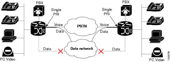
ISDN interfaces can support both data calls and voice calls. Typically, this is done using one interface for data and another for voice. This feature enables data (dial-in, dial-on-demand routing [DDR], and DDR backup) and voice call traffic to occur simultaneously from the supported ISDN PRI interfaces. To enable integrated services, the interface used for incoming voice calls is configured to accept multiple voice call types.
Figure 1 shows an ISDN network configured for integrated data and voice services.
Figure 1 Integrated Voice with DDR Interface for WAN Failure Backup
Resource Allocation for Voice and Data Calls
Voice calls use DSP resources and data calls use HDLC resources for transmission. When an interface is configured for integrated services, the gateway allocates the HDLC resources dynamically during call setup and frees them back to the HDLC resource pools when the call terminates. This allows spare HDLC resources to support ISDN PRI data calls and DSP resources to support voice calls.
MLPP Call Preemption over Voice Calls
Multilevel precedence and preemption (MLPP) is the placement of priority calls through the network. Precedence designates the priority level that is associated with a call. Preemption designates the process of terminating lower-priority calls so that a call of higher precedence can be extended.
Preemption levels are assigned to outgoing voice calls and DDR backup calls. DDR backup is used to provide backup to a WAN link.
From the gateway, voice and DDR backup calls are controlled by different entities:
•
•
A trunk group is used as the common channel resource pool for outgoing voice call and DDR backup calls. Calls with a higher precedence preempt an active outgoing voice call, of a lower precedence, if an idle B channel is not available. An ISDN interface that is configured for integrated mode is assigned to this trunk group to allow dialer resources and voice resources to request an idle B channel from the same resource pool.
Preemption of Outgoing Voice Calls
The trunk group and preemption level are configured as part of a map class, which can be attached to a dialer map. The dialer map class supplies configuration parameters to dialer interfaces and can be referenced from multiple dialer interfaces.
During dial-on-demand routing (DDR) backup call setup, an idle B channel is selected from the trunk group. When no idle channel is found, the trunk group resource manager (TGRM) selects a B channel on the basis of the following:
•
•
A guard timer, configured for the trunk group, is used to delay the idle channel notification and defer the DDR setup to allow the remote channel time to become ready and accept the incoming call with the higher precedence.
By default, the preemption level of dialer calls is set to the lowest level (routine) to disable the MLPP service for a DDR call.
The preemption level of an outgoing voice call is defined from the selected outbound POTS dial peer. During the voice call setup, the trunk group resource manager (TGRM) selects an idle B channel from a trunk group on the basis of the following:
•
•
•
When the preemption call notification is received, the TGRM saves the outgoing voice call to the preemption level link list based on FIFO.
Preemption Tones
When an outgoing voice call is preempted by a DDR backup call, the preemption call treatment starts by providing a preemption tone and starting the tone timer.
An MLPP preemption tone is a special tone played to the voice call announcing that the line is about to be seized by a call with a higher precedence. A steady tone, 1060 ms in duration, is played on all legs of the call until the user hangs up or the preemption tone times out.
•
•
•
Preemption Cause Codes
When the preemption tone timer is expired and the call is still in a connected state, both call legs are disconnected by the gateway with the following cause code:
Preemption - Circuit Reserved 0x8If you release the call before the preemption tone timer expires, the following cause code is used:
Normal Call Clear 0x10In both cases, the following internal cause code is used for the release calls:
Preemption Circuit Reserved 0x8How to Configure Integrated Data and Voice Services for ISDN PRI Interfaces
This section describes the tasks required to configure integrated services for ISDN interfaces:
•
•
Configuring the ISDN PRI Interface for Multiple Call Types
An ISDN serial interface configured for integrated mode supports data and voice calls using incoming call type checking to accept incoming voice and data calls when an inbound voice dial peer is matched.
Perform the following tasks to configure integrated services:
•
•
•
•
Prerequisites
Unlike voice calls, which use DSP resources, data calls use HDLC resources for transmission. To use the integrated services feature, the gateway must allocate HDLC resources dynamically during call setup and free them back to the HDLC resource pools when the call terminates.
Use the following show commands to view the availability of HDLC resources:
•
The following example shows HDLC resources on the TDM side.
Router# show tdm connections slot 0Active TDM connections for slot 0=================================(Key: GT=FLEX TDM, V0=VWIC0, V1=VWIC1, V2=VWIC2, V3=VWIC3IC=EXPANSION, P0=PVDM0, P1=PVDM1, P2=PVDM2, P3=PVDM3HD=HDLC, BP=Backplane(AIM/NM))V0:04/04-->HD:31/18, V0:04/06-->HD:31/06, V0:04/08-->HD:31/12V0:04/10-->HD:31/36, V0:04/12-->HD:31/16, V0:04/14-->HD:31/10V0:04/16-->HD:31/04, V0:04/18-->HD:31/14, V0:04/20-->HD:31/22V0:04/22-->HD:31/20, V0:04/24-->HD:31/24, V0:04/26-->HD:31/30V0:04/28-->HD:31/26, V0:04/30-->HD:31/32, V0:04/32-->HD:31/08V0:04/34-->HD:31/34, V0:04/36-->HD:31/28, V0:04/38-->HD:31/38V0:04/64-->HD:31/00, V0:04/66-->HD:31/02, HD:31/00-->V0:04/64HD:31/02-->V0:04/66, HD:31/04-->V0:04/16, HD:31/06-->V0:04/06HD:31/08-->V0:04/32, HD:31/10-->V0:04/14, HD:31/12-->V0:04/08HD:31/14-->V0:04/18, HD:31/16-->V0:04/12, HD:31/18-->V0:04/04HD:31/20-->V0:04/22, HD:31/22-->V0:04/20, HD:31/24-->V0:04/24HD:31/26-->V0:04/28, HD:31/28-->V0:04/36, HD:31/30-->V0:04/26HD:31/32-->V0:04/30, HD:31/34-->V0:04/34, HD:31/36-->V0:04/10HD:31/38-->V0:04/38,•
In the following example, the -1 listings under the hdlc_chan column show the free HDLC channels.
Router# show controllers Serial 1/1:0Interface Serial1/1:0Hardware is HDLC32HDLC32 resource allocated to this interface:Slot 1, Vic_slot 1, Port 1CRC on 1, idle flags 1, frame inverted 0, clocking 0Channel-group number 0, hdlc32 channel number 2Channel-group bitfield 0x80000000, hdlc32 quad used 0x4Channel HW state: 2TX Ring:data_ptr: 0x0, descriptor: 0x102data_ptr: 0x0, descriptor: 0x102data_ptr: 0x0, descriptor: 0x102data_ptr: 0x0, descriptor: 0x102data_ptr: 0x0, descriptor: 0x102data_ptr: 0x0, descriptor: 0x102data_ptr: 0x0, descriptor: 0x102data_ptr: 0x0, descriptor: 0x102data_ptr: 0x0, descriptor: 0x102data_ptr: 0x0, descriptor: 0x102data_ptr: 0x0, descriptor: 0x102data_ptr: 0x0, descriptor: 0x102data_ptr: 0x0, descriptor: 0x102data_ptr: 0x0, descriptor: 0x102data_ptr: 0x2DD1918C, descriptor: 0xB8830102data_ptr: 0x0, descriptor: 0x102RX Ring:data_ptr: 0x2EE83E04, descriptor: 0x88800102data_ptr: 0x2EE84064, descriptor: 0x88800102data_ptr: 0x2EE842C4, descriptor: 0x88800102data_ptr: 0x2EE84524, descriptor: 0x88800102hdlc_chan hdlc_quad owner_idb chan chan_bitfield vic_slot port========= ========= ========= ==== ============= ======== ====0 1 65C03D5C 15 10000 1 01 2 65CB80F8 15 10000 1 12 4 67B862B0 0 80000000 1 13 8 65C7B1E4 1 40000000 1 14 10 67B8EDFC 2 20000000 1 15 20 65C83D30 3 10000000 1 16 40 67B97948 4 8000000 1 17 80 65C8C87C 5 4000000 1 18 100 67BA0494 6 2000000 1 19 200 65C953C8 7 1000000 1 1-1 0 0 8 800000 1 1-1 0 0 28 8 1 1-1 0 0 0 0 0 0-1 0 0 0 0 0 0-1 0 0 0 0 0 0-1 0 0 0 0 0 0-1 0 0 0 0 0 0-1 0 0 0 0 0 0-1 0 0 0 0 0 0-1 0 0 0 0 0 0-1 0 0 0 0 0 0-1 0 0 0 0 0 0-1 0 0 0 0 0 0-1 0 0 0 0 0 0-1 0 0 0 0 0 0-1 0 0 0 0 0 0-1 0 0 0 0 0 0-1 0 0 0 0 0 0-1 0 0 0 0 0 0-1 0 0 0 0 0 0-1 0 0 0 0 0 0-1 0 0 0 0 0 0Configuring the POTS Dial-Peer Incoming Called Number
The call type of an incoming call is determined using the incoming dial-peer. For data dial peer matching, the called number of an incoming call is used to match the incoming called-number of POTS dial peers. Use the following procedure to configure the POTS dial peer and incoming called number.
SUMMARY STEPS
1.
2.
3.
4.
DETAILED STEPS
Configuring the Data Dial Peer Lookup Preference
To optimize data or voice dial-peer searches for incoming ISDN calls, configure the preference of dial-peer lookup during the call type checking. Use the following procedure to configure a search for dial peers by type.
SUMMARY STEPS
1.
2.
3.
DETAILED STEPS
Enabling Integrated Services
Enabling integrated services allows data and voice call traffic to occur from ISDN PRI interfaces simultaneously.
When an interface is in integrated service mode:
•
•
By default, the integrated service option is disabled from the supported interfaces. Use the following procedure to enable integrated mode on a serial interface.
SUMMARY STEPS
1.
2.
3.
4.
5.
6.
DETAILED STEPS
Creating a Trunkgroup and Configuring Maximum Calls Based on Call Type
After an ISDN interface is assigned to a trunk group, you can configure maximum incoming and outgoing calls based on the call type (voice or data) or direction (inbound or outbound) through the trunk group.
Note
Use the following procedure to create a trunk group and configure maximum calls based on call type.
SUMMARY STEPS
1.
2.
3.
4.
DETAILED STEPS
Examples
See the following sample configurations for the max-calls command:
•
trunk group 1max-calls data 7•
trunk group 2max-calls data 2 direction inmax-calls data 3 direction outmax-calls voice 16•
trunk group 3max-calls any 10 direction inDisabling Integrated Services
When the isdn integrate calltype all command is removed from the interface, the isdn incoming-voice voice setting is restored and the interface returns to voice mode. Use the following procedure to remove the integrated services option from the interface.
1.
2.
3.
4.
5.
6.
DETAILED STEPS
Configuring MLPP Call Preemption over Outgoing Voice Calls
This feature adds support for multilevel precedence and preemption (MLPP) for dial-on-demand routing (DDR) backup calls over outgoing voice calls.
Precedence designates the priority level that is associated with a call. Preemption designates the process of terminating lower-precedence calls so that a call of higher precedence can be extended. DDR backup is used to provide backup to a WAN link using any DDR or a dial-capable interface, like ISDN PRI interfaces.
From the gateway, voice and DDR backup calls are controlled by different entities.
•
•
A DDR backup call with higher precedence preempts the active outgoing voice call with a lower precedence if the idle B channel is not available from a trunk group during the DDR backup call setup. If MLPP is not configured, data calls wait for a free channel.
Perform the following tasks to configure call preemption:
•
•
•
•
•
•
Enabling Preemption on the Trunk Group
A trunk group is used as a common channel resource pool for idle channel allocation for outgoing voice calls and DDR backup calls. Multiple ISDN PRI interfaces that have been configured for integrated services are assigned to this trunk group to build up a channel resource pool for both voice and data calls. Enabling preemption on the trunk group allows DDR call preemption over a voice call per trunk group.
Note
The tone timer defines the expiry timer for the preemption tone for the outgoing voice call, which is being preempted by a DDR backup call. When the tone timer expires, the call is disconnected.
Use the following procedure to create a trunk group resource pool and enable preemption on the trunk group.
SUMMARY STEPS
1.
2.
3.
4.
5.
6.
DETAILED STEPS
Defining a Dialer Map Class and Setting the Preemption Level
During dial-on-demand routing (DDR) call setup, an idle B channel is selected from the trunk group. The trunk group and preemption level are configured as part of a map class, which can be attached to a dialer map or dialer string. By default, the preemption level of dialer calls is set to the lowest level (routine) to disable the MLPP service for a DDR call.
Use the following procedure to define a map class for the dialer interface.
SUMMARY STEPS
1.
2.
3.
4.
5.
DETAILED STEPS
Associating the Class Parameter on the Dialer Interface
The trunk group preemption level is configured as part of a map class, which can be attached to a dialer map or dialer string.
•
•
Use the following procedure to associate the class parameter on the dialer interface.
SUMMARY STEPS
1.
2.
3.
4.
or
dialer pool number
5.
or
dialer string dial-string [class class-name]
DETAILED STEPS
Examples
Legacy DDR Example
interface Dialer11ip address 172.22.82.1 255.255.255.0encapsulation pppdialer in-banddialer map ip 172.22.82.2 name gw3845 class dial1 20009dialer load-threshold 1 outbounddialer-group 1ppp callback acceptppp authentication chapppp multilinkmap-class dialer dial1dialer trunkgroup 1dialer preemption level flash-overrideDialer Profiles Example
interface Dialer10ip address 192.168.254.1 255.255.255.0dialer pool 1dialer remote-name is2811dialer string 4081234 class testdialer-group 1map-class dialer testdialer trunkgroup 1dialer preemption level flash-overrideDisabling TDM Hairpinning on the Voice Card
For TDM-only calls, or for calls that are hairpinned, the preemption tone is not heard as the DSPs are dropped. For this reason, you must disable TDM hairpinning on the voice card to use the MLPP DDR backup call preemption feature.
Use the following procedure to disable TDM hairpinning on the voice card.
SUMMARY STEPS
1.
2.
3.
4.
DETAILED STEPS
Configuring the POTS Dial Peer for Outgoing Voice Calls
The preemption level of an outgoing voice call is defined from the outbound POTS dial peer. The preemption level defines the preemption priority level of an outgoing voice call. Use the following procedure to set the preemption level for outgoing voice calls on a POTS dial peer.
SUMMARY STEPS
1.
2.
3.
4.
5.
DETAILED STEPS
Troubleshooting Tips for Integrated Data and Voice Services
ISDN call failures are most commonly attributed to the following issues:
•
•
•
Use the following commands to troubleshoot integrated data and voice for ISDN interfaces:
•
•
•
•
•
•
•
•
Configuration Examples for Integrating Data and Voice Services for ISDN PRI Interfaces
This section provides the following configuration examples:
•
•
•
•
MLPP DDR Backup Call Preemption over Voice Call: Example
The following example shows that preemption is enabled on the trunk group, the trunk group is associated with a map class, and the preemption level is set on the dialer interface.
Router# show running-configBuilding configuration...Current configuration : 5984 bytes!version 12.3service timestamps debug datetime msecservice timestamps log datetime msecno service password-encryption!hostname Router!boot-start-markerboot-end-marker!card type e1 0 3no logging buffered!no aaa new-model!resource manager!network-clock-participate slot 1network-clock-participate wic 3ip subnet-zero!!ip cefno ip dhcp use vrf connected!ip dhcp pool ITSnetwork 10.0.0.0 255.255.0.0option 150 ip 10.0.0.1default-router 10.0.0.1!!no ip domain lookupip name-server 192.168.2.87ftp-server enableno ftp-server write-enableftp-server topdir flash:/isdn switch-type primary-ntt!!trunk group 1 max-calls data 10 direction out preemption enable preemption tone 4!voice-card 0dspfarmno local-bypass!voice-card 1dspfarmno local-bypass!!voice call send-alert!!!controller E1 0/3/0clock source internalpri-group timeslots 1-5,16trunk-group 1 timeslots 1-5!controller E1 0/3/1clock source internalpri-group timeslots 1-2,16trunk-group 1 timeslots 1-2!controller E1 1/0/0clock source internalpri-group timeslots 1-31trunk-group 1 timeslots 1-31!controller E1 1/0/1clock source internalpri-group timeslots 1-10,16trunk-group 1 timeslots 1-10!!!interface Loopback0ip address 10.10.1.1 255.255.255.255!interface GigabitEthernet0/0ip address 10.3.202.87 255.255.0.0no ip proxy-arpduplex autospeed auto!interface GigabitEthernet0/1ip address 10.0.0.2 255.255.0.0shutdownduplex autospeed auto!interface FastEthernet0/1/0switchport access vlan 2no ip addressload-interval 30duplex fullspeed 100!interface FastEthernet0/1/1no ip address!interface FastEthernet0/1/2no ip address!interface FastEthernet0/1/3no ip address!interface FastEthernet0/1/4no ip address!interface FastEthernet0/1/5no ip address!interface FastEthernet0/1/6no ip address!interface FastEthernet0/1/7no ip address!interface FastEthernet0/1/8no ip address!interface Serial0/2/0no ip addressencapsulation frame-relayload-interval 30shutdownno keepaliveclockrate 2000000!interface Serial0/2/0.1 point-to-pointip address 10.3.3.1 255.255.255.0frame-relay interface-dlci 100!interface Serial0/2/1no ip addressshutdownclockrate 2000000!interface Serial0/3/0:15no ip addressdialer pool-member 1isdn switch-type primary-nttisdn protocol-emulate networkisdn T310 15000isdn bchan-number-order descendingisdn integrate calltype allno cdp enable!interface Serial0/3/1:15no ip addressdialer pool-member 1isdn switch-type primary-nttisdn protocol-emulate networkisdn T310 15000isdn bchan-number-order descendingisdn integrate calltype allno cdp enable!interface Serial1/0/0:15no ip addressdialer pool-member 1isdn switch-type primary-dms100isdn protocol-emulate networkisdn T310 15000isdn bchan-number-order descendingisdn integrate calltype allno cdp enable!interface Serial1/0/1:15no ip addressencapsulation pppdialer pool-member 1isdn switch-type primary-nttisdn protocol-emulate networkisdn T310 15000isdn bchan-number-order descendingisdn integrate calltype allppp multilink!interface Vlan1ip address 10.0.0.1 255.255.0.0load-interval 30!interface Vlan2ip address 10.7.7.7 255.255.0.0!interface Dialer0ip address 10.5.5.5 255.0.0.0encapsulation pppload-interval 30dialer pool 1dialer remote-name Routerdialer string 4081234 class testdialer load-threshold 10 outbounddialer-group 1ppp multilinkppp multilink load-threshold 5 outbound !interface Dialer1ip address 192.168.253.1 255.255.255.0dialer pool 1dialer string 4085678 class testdialer-group 1!interface Dialer2ip address 192.168.252.1 255.255.255.0dialer pool 1dialer string 4087777 class testdialer-group 1!ip default-gateway 5.5.5.6ip classlessip route 172.16.254.254 255.255.255.255 10.3.0.1 !ip http server!!map-class dialer testdialer trunkgroup 1dialer preemption level flashdialer-list 1 protocol ip permitsnmp-server community public ROsnmp-server enable traps tty!!!control-plane!!!voice-port 0/3/0:15echo-cancel enable type hardware!voice-port 0/3/1:15echo-cancel enable type hardware!voice-port 1/0/0:15compand-type u-law!voice-port 1/0/1:15!voice-port 2/0/0shutdown!voice-port 2/0/1!voice-port 2/0/2!voice-port 2/0/3!voice-port 2/0/4!voice-port 2/0/5!voice-port 2/0/6!voice-port 2/0/7!!!!!!dial-peer voice 100 potsdestination-pattern 1...port 2/0/1forward-digits all!dial-peer voice 2001 potstrunkgroup 1destination-pattern 2...forward-digits all!dial-peer voice 3001 potstrunkgroup 1destination-pattern 3...forward-digits all!dial-peer voice 300 potsdestination-pattern 4...port 2/0/2forward-digits all!dial-peer voice 10 potsincoming called-number .direct-inward-dialforward-digits 0!dial-peer voice 5001 potstrunkgroup 1destination-pattern 5...forward-digits all!dial-peer voice 500 potsdestination-pattern 6...port 2/0/3forward-digits all!dial-peer voice 800 potstrunkgroup 1destination-pattern 8...forward-digits all!dial-peer data 50 potsincoming called-number 650T!!!telephony-serviceload 7960-7940 P00303020214max-ephones 5max-dn 5ip source-address 10.0.0.1 port 2000create cnf-files version-stamp Jan 01 2002 00:00:00 max-conferences 8 gain -6 transfer-system full-consult transfer-pattern .T !!ephone-dn 1 dual-linenumber 7000!!ephone-dn 2number 7002!!ephone-dn 3number 1003!!ephone-dn 4number 1004!!ephone 1mac-address 0030.94C2.6073type 7960button 1:1!!!ephone 2mac-address 000C.851C.ED81type 7960button 1:2!!!ephone 3!!!ephone 4!!alias exec c conf talias exec s sh run!line con 0exec-timeout 0 0privilege level 15line aux 0line vty 0 4login!scheduler allocate 20000 1000!endLegacy DDR (Dialer Map): Example
The following example shows how to associate the class parameter for legacy DDR.
Router# show running-configBuilding configuration...Current configuration : 1358 bytes!version 12.3service timestamps debug datetime msecservice timestamps log datetime msecno service password-encryption!hostname host2!boot-start-markerboot-end-marker!card type t1 1!username client password 0 labmemory-size iomem 10no network-clock-participate aim 0no network-clock-participate aim 1no aaa new-modelip subnet-zero!ip cef!ip ips po max-events 100no ftp-server write-enableisdn switch-type primary-ni!controller T1 1/0framing esflinecode b8zscablelength long 0dbpri-group timeslots 1-24!controller T1 1/1framing sflinecode amicablelength long 0db!interface FastEthernet0/0ip address 10.10.193.77 255.255.0.0duplex autospeed auto!interface FastEthernet0/1ip address 192.168.10.1 255.255.255.0shutdownduplex autospeed auto!interface Serial1/0:23ip address 192.168.254.2 255.255.255.0encapsulation pppdialer map ip 172.22.82.2 name gw3845 class dial1 20009dialer-group 2isdn switch-type primary-nippp authentication chap!no ip classlessip route 10.10.1.0 255.255.255.0 192.168.254.1ip route 172.16.254.0 255.255.255.0 10.10.0.1!ip http serverno ip http secure-server!dialer-list 2 protocol ip permit!control-plane!line con 0line aux 0line vty 0 4login!scheduler allocate 20000 1000!endDialer Profiles: Example
The following example shows how to associate the class parameter for dialer profiles.
Router# show running-configBuilding configuration...Current configuration : 1689 bytes!version 12.3service timestamps debug datetime msecservice timestamps log datetime msecno service password-encryption!hostname host3!boot-start-markerboot-end-marker!card type t1 1no logging console!username uut password 0 labno network-clock-participate aim 0no network-clock-participate aim 1no aaa new-modelip subnet-zero!ip cef!ip ips po max-events 100no ftp-server write-enableisdn switch-type primary-ni!controller T1 1/0framing esflinecode b8zscablelength long 0dbpri-group timeslots 1-24!controller T1 1/1framing sflinecode amicablelength long 0db!no crypto isakmp enable!interface FastEthernet0/0ip address 10.10.193.88 255.255.0.0duplex autospeed auto!interface FastEthernet0/1ip address 10.10.1.1 255.255.255.0duplex autospeed auto!interface Serial0/3/0no ip addressclockrate 2000000!interface Serial0/3/1no ip addressclockrate 2000000!interface Serial1/0:23no ip addressencapsulation pppdialer pool-member 1isdn switch-type primary-niisdn protocol-emulate networkisdn T310 30000isdn bchan-number-order descendingppp authentication chap!iinterface Dialer2ip address 192.168.252.1 255.255.255.0dialer pool 1dialer string 4087777 class testdialer-group 1!ip default-gateway 5.5.5.6ip classlessip route 172.16.254.254 255.255.255.255 10.3.0.1 !ip http server!!map-class dialer testdialer trunkgroup 1dialer preemption level flashdialer-list 1 protocol ip permitsnmp-server community public ROsnmp-server enable traps tty!dialer-list 1 protocol ip permit!control-plane!line con 0exec-timeout 0 0line aux 0line vty 0 4login!scheduler allocate 20000 8000endMaximum Number of Data and Voice Calls on the Dial-Out Trunk Group: Example
The following sample configuration shows a maximum number of 500 data and voice calls configured on the trunk group, includes all B channels in the trunk group, and associates dialer test with the trunk group.
Router# show running-configBuilding configuration...Current configuration : 2283 bytes!version 12.3service timestamps debug datetime msecservice timestamps log datetime msecno service password-encryption!hostname host4!boot-start-markerboot-end-marker!card type t1 1 1no logging console!no aaa new-model!resource manager!no network-clock-participate slot 1ip subnet-zero!ip cef!no ftp-server write-enableisdn switch-type primary-ni!trunk group 1max-calls any 500!voice-card 0dspfarm!voice-card 1dspfarm!controller T1 1/0framing esflinecode b8zs!controller T1 1/0/0framing esflinecode b8zspri-group timeslots 1-12,24!controller T1 1/0/1framing esflinecode b8zs!interface GigabitEthernet0/0ip address 10.10.212.212 255.255.0.0duplex autospeed auto!interface GigabitEthernet0/1no ip addressduplex autospeed auto!interface Serial1/0/0:23no ip addressdialer pool-member 1isdn switch-type primary-niisdn protocol-emulate networkisdn T310 30000isdn bchan-number-order descendingisdn integrate calltype alltrunk-group 1 1no cdp enable!interface Dialer0ip address 192.168.254.1 255.255.255.0dialer pool 1dialer string 4081234 class testdialer-group 1!interface Dialer1ip address 192.168.253.1 255.255.255.0dialer pool 1dialer string 4085678 class testdialer-group 1!interface Dialer2ip address 192.168.252.1 255.255.255.0dialer pool 1dialer string 4087777 class testdialer-group 1!ip classlessip route 192.168.10.0 255.255.255.0 Dialer0ip route 192.168.11.0 255.255.255.0 Dialer1ip route 192.168.12.0 255.255.255.0 Dialer2ip route 172.16.254.254 255.255.255.255 GigabitEthernet0/0!ip http server!map-class dialer testdialer trunkgroup 1dialer-list 1 protocol ip permit!control-plane!voice-port 1/0/0:23!voice-port 2/0/0!voice-port 2/0/1!voice-port 2/0/2!voice-port 2/0/3!voice-port 2/0/4!voice-port 2/0/5!voice-port 2/0/6!voice-port 2/0/7!dial-peer voice 100 potsdestination-pattern 1001port 2/0/0forward-digits all!dial-peer voice 2001 potsdestination-pattern 200.port 1/0/0:23forward-digits all!dial-peer voice 101 potsdestination-pattern 1002port 2/0/1!line con 0exec-timeout 0 0line aux 0line vty 0 4login!scheduler allocate 20000 1000!endDial-Peer Configuration: Example
Data dial peers enable the configuration and order assignment of dial peers so that the gateway can identify incoming calls as voice or data. The incoming called number specifies the number associated with the data dial peer. The following example shows a configuration for the voice and data dial-peers and incoming called number.
Router# show running-configBuilding configuration...Current configuration : 1978 bytes!version 12.3service timestamps debug datetime msecservice timestamps log datetime msecno service password-encryption!hostname host6!boot-start-markerboot-end-marker!no aaa new-model!resource manager!no network-clock-participate slot 1ip subnet-zero!ip cef!no ftp-server write-enableisdn switch-type primary-ni!trunk group 1max-calls any 2!voice-card 0dspfarm!voice-card 1dspfarm!controller T1 1/1/0framing esflinecode b8zspri-group timeslots 1-12,24trunk-group 1 timeslots 2!controller T1 1/1/1framing esflinecode b8zs!interface FastEthernet0/0ip address 10.10.193.90 255.255.0.0duplex halfspeed 10!interface FastEthernet0/1no ip addressshutdownduplex autospeed auto!interface FastEthernet0/1/0no ip addressshutdown!interface FastEthernet0/1/1no ip addressshutdown!interface FastEthernet0/1/2no ip addressshutdown!interface FastEthernet0/1/3no ip addressshutdown!interface Serial1/1/0:23no ip addressdialer pool-member 2isdn switch-type primary-niisdn integrate calltype allno cdp enable!interface Vlan1no ip address!interface Dialer0ip address 192.168.254.2 255.255.255.0dialer pool 2dialer string 6501234dialer-group 2!ip classlessip route 10.10.1.0 255.255.255.0 Dialer0ip route 172.16.254.0 255.255.255.0 10.10.0.1!ip http server!dialer-list 2 protocol ip permit!control-plane!voice-port 0/2/0!voice-port 0/2/1!voice-port 0/2/2!voice-port 0/2/3!voice-port 1/1/0:23!dial-peer voice 100 potsdestination-pattern 2001port 0/2/0forward-digits all!dial-peer voice 10 potsincoming called-number .direct-inward-dialport 1/1/0:23!dial-peer data 50 potsincoming called-number 408T!dial-peer voice 101 potsdestination-pattern 2002port 0/2/1forward-digits all!line con 0exec-timeout 0 0line aux 0line vty 0 4login!scheduler allocate 20000 1000!endDisconnect Cause: Example
This example shows the DisconnectCause information for a preemption call.
Router#show call history voiceTelephony call-legs: 2 SIP call-legs: 0 H323 call-legs: 0 Call agent controlled call-legs: 0 Total call-legs: 2 GENERIC: SetupTime=281680 ms Index=1 PeerAddress=7002 PeerSubAddress= PeerId=20002 PeerIfIndex=161 LogicalIfIndex=160DisconnectCause=8 DisconnectText=preemption (8)ConnectTime=286160 ms DisconnectTime=441190 ms CallDuration=00:02:35 sec CallOrigin=2 ReleaseSource=7 InternalErrorCode=1.1.8.11.35.0 ChargedUnits=0 InfoType=speech TransmitPackets=0 TransmitBytes=0 ReceivePackets=6910 ReceiveBytes=1105600 TELE: ConnectionId=[0x4E9D9EF1 0x23E411DA 0x8002A31F 0xB25BECEF] IncomingConnectionId=[0x4E9D9EF1 0x23E411DA 0x8002A31F 0xB25BECEF] CallID=1 TxDuration=0 ms VoiceTxDuration=0 ms FaxTxDuration=0 ms CoderTypeRate=g711ulaw NoiseLevel=0 ACOMLevel=0 SessionTarget= ImgPages=0 CallerName= CallerIDBlocked=False OriginalCallingNumber=7002 OriginalCallingOctet=0x0 OriginalCalledNumber= OriginalCalledOctet=0x80 OriginalRedirectCalledNumber= OriginalRedirectCalledOctet=0x0 TranslatedCallingNumber=7002 TranslatedCallingOctet=0x0 TranslatedCalledNumber= TranslatedCalledOctet=0x80 TranslatedRedirectCalledNumber= TranslatedRedirectCalledOctet=0x0 GwCollectedCalledNumber=2000 GwReceivedCallingNumber=7002 GwReceivedCallingOctet3=0x0 GwReceivedCallingOctet3a=0x0 GENERIC: SetupTime=282800 ms Index=2 PeerAddress=2000 PeerSubAddress= PeerId=2001 PeerIfIndex=144 LogicalIfIndex=42 DisconnectCause=8 DisconnectText=preemption (8) ConnectTime=286160 ms DisconnectTime=441210 ms CallDuration=00:02:35 sec CallOrigin=1 ReleaseSource=7 InternalErrorCode=1.1.8.11.35.0 ChargedUnits=0 InfoType=speech TransmitPackets=6910 TransmitBytes=1160880 ReceivePackets=6917 ReceiveBytes=1106720 TELE: ConnectionId=[0x4E9D9EF1 0x23E411DA 0x8002A31F 0xB25BECEF] IncomingConnectionId=[0x4E9D9EF1 0x23E411DA 0x8002A31F 0xB25BECEF] CallID=2 TxDuration=0 ms VoiceTxDuration=0 ms FaxTxDuration=0 ms CoderTypeRate=g711ulaw NoiseLevel=-41 ACOMLevel=26 SessionTarget= ImgPages=0 CallerName= CallerIDBlocked=False AlertTimepoint=282820 ms Target tg label=1 OriginalCallingNumber=7002 OriginalCallingOctet=0x0 OriginalCalledNumber= OriginalCalledOctet=0x80 OriginalRedirectCalledNumber= OriginalRedirectCalledOctet=0x0 TranslatedCallingNumber=7002 TranslatedCallingOctet=0x0 TranslatedCalledNumber=2000 TranslatedCalledOctet=0x80 TranslatedRedirectCalledNumber= TranslatedRedirectCalledOctet=0x0 GwCollectedCalledNumber=2000 GwOutpulsedCalledNumber=2000 GwOutpulsedCalledOctet3=0x80 GwReceivedCallingNumber=7002 GwReceivedCallingOctet3=0x0 GwReceivedCallingOctet3a=0x0 GwOutpulsedCallingNumber=7002 GwOutpulsedCallingOctet3=0x0 GwOutpulsedCallingOctet3a=0x0 DSPIdentifier=0/1:1Additional References
The following sections provide references related to configuring integrated data and voice for ISDN interfaces.
Related Documents
Cisco IOS Voice Configuration Library, including library preface and glossary, other feature documents, and troubleshooting documentation.
Voice command reference
Cisco IOS ISDN voice technologies
Cisco dial technologies
•
ISDN PRI configuration information
Configuring Network Side ISDN PRI Signaling, Trunking, and Switching
Multilevel precedence and preemption (MLPP) information
ISDN voice interface information.
Standards
No new or modified standards are supported by this feature, and support for existing standards has not been modified by this feature.
MIBs
RFCs
No new or modified RFCs are supported by this feature, and support for existing RFCs has not been modified by this feature.
Technical Assistance
Command Reference
This section documents the following new and modified commands:
New Commands
Modified Commands
debug voip ccapi
To troubleshoot the call control application programming interface (CCAPI) contents, use the debug voip ccapi command in privileged EXEC mode. To disable debugging output, use the no form of this command.
debug voip ccapi [all | default | detail | error [call [informational] | software [informational]] | individual range | inout | function | protoheaders | service]
no debug voip ccapi
Syntax Description
all
(Optional) Displays all CCAPI debugging messages.
default
(Optional) Displays CCAPI error and inout information. This option also runs if no keywords are added.
detail
(Optional) Displays CCAPI background messages.
error
(Optional) Displays CCAPI error messages. The debug voip ccapi error command traces the error logs in the call control API. Error logs are generated during normal call processing, if there are insufficient resources, or if there are problems in the underlying network-specific code, the higher call session application, or the call control API itself.
This debug command shows error events or unexpected behavior in system software. Usually no events will be generated.
call
(Optional) Displays call processing errors.
informational
(Optional) Displays minor errors and major errors. Without the informational keyword, only major errors are displayed.
software
(Optional) Displays software errors.
individual
(Optional) Enables individual CCAPI debug outputs.
range
For the individual keyword, the range is an integer value from 1 to 146. For specific range values, see Table 1.
inout
(Optional) Displays CCAPI in/out functions. The debug voip ccapi inout command traces the execution path through the call control API, which serves as the interface between the call session application and the underlying network-specific software. You can use the output from this command to understand how calls are being handled by the router.
This command shows how a call flows through the system. Using this debug level, you can see the call setup and teardown operations performed on both the telephony and network call legs.
function
(Optional) Displays CCAPI function tracing.
protoheaders
(Optional) Displays CCAPI protocol headers passing information.
service
(Optional) Logs debug messages that are not call related.
Command Default
Debugging is not enabled.
Command Modes
Privileged EXEC
Command History
Examples
The following examples show output for variations of the debug voip ccapi command:
•
•
•
•
•
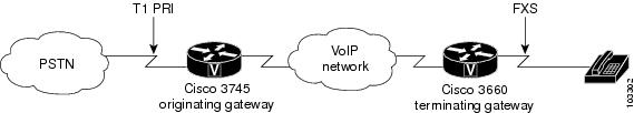
For these examples, the topology shown in Figure 2 is used.
Figure 2 Network Topology for debug voip ccapi Output Examples
debug voip ccapi detail on the Originating Gateway: Example
Router# debug voip ccapi detailvoip ccapi detail debugging is onRouter#*Apr 18 20:35:35.779: //-1/ABCE697D8005/CCAPI/cc_api_call_setup_ind_common:Interface Type=13, Protocol=0*Apr 18 20:35:35.779: //-1/ABCE697D8005/CCAPI/ccCheckClipClir:Calling Party Number Is User Provided*Apr 18 20:35:35.779: //11/xxxxxxxxxxxx/CCAPI/cc_insert_call_entry:Total Call Count=0, Call Entry(Call Count On=FALSE, Incoming Call=TRUE)*Apr 18 20:35:35.779: //11/xxxxxxxxxxxx/CCAPI/cc_insert_call_entry:Total Call Count=1The following event shows that the CallEntry ID 11 is used for the incoming call leg.
*Apr 18 20:35:35.779: //11/ABCE697D8005/CCAPI/cc_insert_guid_pod_entry:Incoming=TRUE, Call Id=11*Apr 18 20:35:35.779: //11/ABCE697D8005/CCAPI/cc_setupind_registration_lookup:Matching Parameters; Called Number=83103, Call Transfer Consult Id=*Apr 18 20:35:35.779: //11/ABCE697D8005/CCAPI/cc_setupind_registration_lookup:No Matching Node*Apr 18 20:35:35.779: //11/ABCE697D8005/CCAPI/ccCheckClipClir:Calling Party Number Is User Provided*Apr 18 20:35:35.779: //12/xxxxxxxxxxxx/CCAPI/cc_insert_call_entry:Total Call Count=1, Call Entry(Call Count On=FALSE, Incoming Call=FALSE)The following event shows that the incoming call leg with CallEntry ID 11 is bound to the outgoing call leg with CallEntry ID 12.
*Apr 18 20:35:35.779: //11/ABCE697D8005/CCAPI/cc_peer_bind:Bind=TRUE, Binder Call Id=11, Bindee Call Id=12The next event shows that CallEntry ID 12 is used for the outgoing call leg.
*Apr 18 20:35:35.779: //12/ABCE697D8005/CCAPI/cc_insert_guid_pod_entry:Incoming=FALSE, Call Id=12*Apr 18 20:35:35.779: //-1/xxxxxxxxxxxx/CCAPI/cc_api_supported_data:data_mode=0x10082The next event shows an IP address for a remote device on the outgoing call leg, which indicates that this is the VoIP call leg.
*Apr 18 20:35:35.779: //12/ABCE697D8005/CCAPI/cc_incr_if_call_volume:Remote IP Address=172.16.13.81, Hwidb=FastEthernet0/0*Apr 18 20:35:35.779: //12/ABCE697D8005/CCAPI/cc_incr_if_call_volume:Total Call Count=1, Voip Call Count=1, MMoip Call Count=0*Apr 18 20:35:35.795: //11/ABCE697D8005/CCAPI/ccCallGetContext:Context=0x652C0168, Call Id=11*Apr 18 20:36:31.419: //11/ABCE697D8005/CCAPI/ccCallDisconnect:Start Calling Accounting;Call Entry(Incoming=TRUE)*Apr 18 20:36:31.419: //11/ABCE697D8005/CCAPI/ccCallDisconnect:Cause Value=16, Call Entry(Disconnect Cause=16)*Apr 18 20:36:31.419: //11/ABCE697D8005/CCAPI/ccCallDisconnect:Call Entry(Disconnect Cause=16)At this point, the CallEntry ID changes as the call accounting process begins. The accounting data is sent over the outgoing call leg. The GUID, which identifies the unique call, remains the same.
*Apr 18 20:36:31.419: //12/ABCE697D8005/CCAPI/ccCallDisconnect:Start Calling Accounting;Call Entry(Incoming=FALSE)*Apr 18 20:36:31.419: //12/ABCE697D8005/CCAPI/ccCallDisconnect:Cause Value=16, Call Entry(Disconnect Cause=0)The change of the CallEntry ID indicates that the call is using the incoming call leg, which is the POTS call leg in this case.
*Apr 18 20:36:31.423: //11/ABCE697D8005/CCAPI/ccCallGetVoipFlag:Data Bitmask=0x1, Call Id=11*Apr 18 20:36:31.423: //11/ABCE697D8005/CCAPI/ccCallGetVoipFlag:Flag=FALSE*Apr 18 20:36:31.423: //11/ABCE697D8005/CCAPI/cc_delete_guid_pod_entry:Incoming=TRUE*Apr 18 20:36:31.423: //11/ABCE697D8005/CCAPI/cc_delete_call_entry:ccFreeRawMsgInfo=0x63FF8198*Apr 18 20:36:31.423: //11/ABCE697D8005/CCAPI/cc_delete_call_entry:Total Call Count=1, Call Entry(Call Count On=FALSE, Incoming Call=TRUE)*Apr 18 20:36:31.423: //11/ABCE697D8005/CCAPI/cc_delete_call_entry:Total Call Count=0*Apr 18 20:36:31.423: //11/ABCE697D8005/CCAPI/cc_delete_call_entry:Deleting profileTable[0x64F44700]The next line shows the impairment calculation. This is the only CCAPI debug command that shows impairment.
*Apr 18 20:36:31.423: //-1/ABCE697D8005/CCAPI/g113_calculate_impairment:(delay=91(ms), loss=0%), Io=0 Iq=0 Idte=0 Idd=2 Ie=10 Itot=12*Apr 18 20:36:31.423: //12/ABCE697D8005/CCAPI/ccCallGetVoipFlag:Data Bitmask=0x1, Call Id=12*Apr 18 20:36:31.423: //12/ABCE697D8005/CCAPI/ccCallGetVoipFlag:Flag=FALSE*Apr 18 20:36:31.423: //12/ABCE697D8005/CCAPI/cc_decr_if_call_volume:Remote IP Address=172.16.13.81, Hwidb=FastEthernet0/0*Apr 18 20:36:31.423: //12/ABCE697D8005/CCAPI/cc_decr_if_call_volume:Total Call Count=0, Voip Call Count=0, MMoip Call Count=0*Apr 18 20:36:31.423: //12/ABCE697D8005/CCAPI/cc_delete_guid_pod_entry:Incoming=FALSE*Apr 18 20:36:31.423: //12/ABCE697D8005/CCAPI/cc_delete_call_entry:Total Call Count=0, Call Entry(Call Count On=FALSE, Incoming Call=FALSE)*Apr 18 20:36:31.423: //12/ABCE697D8005/CCAPI/cc_delete_call_entry:Deleting profileTable[0x652E3310]*Apr 18 20:36:31.427: //12/xxxxxxxxxxxx/CCAPI/cc_get_call_entry:Call Entry Is Not Founddebug voip ccapi detail on the Terminating Gateway: Example
Router# debug voip ccapi detailvoip ccapi detail debugging is onRouter#*May 1 18:58:26.251: //-1/xxxxxxxxxxxx/CCAPI/cc_api_supported_data:data_mode=0x10082*May 1 18:58:26.255: //8/xxxxxxxxxxxx/CCAPI/cc_get_call_entry:Call Entry Is Not Found*May 1 18:58:26.255: //-1/ABCE697D8005/CCAPI/cc_api_call_setup_ind_common:Interface Type=0, Protocol=1*May 1 18:58:26.255: //-1/ABCE697D8005/CCAPI/ccCheckClipClir:Calling Party Number Is User ProvidedThe following line shows the attributes of the calling number:
*May 1 18:58:26.255: //-1/ABCE697D8005/CCAPI/cc_api_call_setup_ind_common:After Number Translation Checking:Calling Number=4085550111(TON=National, NPI=ISDN, Screening=User, Passed, Presentation=Allowed),Called Number=3600(TON=Unknown, NPI=Unknown)*May 1 18:58:26.255: //8/xxxxxxxxxxxx/CCAPI/cc_insert_call_entry:Total Call Count=0, Call Entry(Call Count On=FALSE, Incoming Call=TRUE)*May 1 18:58:26.255: //8/xxxxxxxxxxxx/CCAPI/cc_insert_call_entry:Total Call Count=1*May 1 18:58:26.255: //8/ABCE697D8005/CCAPI/cc_insert_guid_pod_entry:Incoming=TRUE, Call Id=8The following line shows the IP address of the originating gateway:
*May 1 18:58:26.255: //8/ABCE697D8005/CCAPI/cc_incr_if_call_volume:Remote IP Address=172.16.13.175, Hwidb=FastEthernet0/0*May 1 18:58:26.255: //8/ABCE697D8005/CCAPI/cc_incr_if_call_volume:Total Call Count=1, Voip Call Count=1, MMoip Call Count=0*May 1 18:58:26.255: //8/ABCE697D8005/CCAPI/cc_setupind_registration_lookup:Matching Parameters; Called Number=3600, Call Transfer Consult Id=*May 1 18:58:26.255: //8/ABCE697D8005/CCAPI/cc_setupind_registration_lookup:No Matching Node*May 1 18:58:26.255: //8/ABCE697D8005/CCAPI/ccCheckClipClir:Calling Party Number Is User Provided*May 1 18:58:26.259: //9/xxxxxxxxxxxx/CCAPI/cc_insert_call_entry:Total Call Count=1, Call Entry(Call Count On=FALSE, Incoming Call=FALSE)*May 1 18:58:26.259: //8/ABCE697D8005/CCAPI/cc_peer_bind:Bind=TRUE, Binder Call Id=8, Bindee Call Id=9*May 1 18:58:26.259: //9/ABCE697D8005/CCAPI/cc_insert_guid_pod_entry:Incoming=FALSE, Call Id=9*May 1 18:58:26.259: //9/ABCE697D8005/CCAPI/cc_set_voice_port_value:CC_IF_TELEPHONY: Echo=0, Playout=0*May 1 18:58:26.263: //9/ABCE697D8005/CCAPI/ccCallGetContext:Context=0x64B6BB5C, Call Id=9*May 1 18:59:21.871: //8/ABCE697D8005/CCAPI/ccCallDisconnect:Start Calling Accounting;Call Entry(Incoming=TRUE)*May 1 18:59:21.875: //8/ABCE697D8005/CCAPI/ccCallDisconnect:Cause Value=16, Call Entry(Disconnect Cause=16)*May 1 18:59:21.875: //8/ABCE697D8005/CCAPI/ccCallDisconnect:Call Entry(Disconnect Cause=16)*May 1 18:59:21.875: //9/ABCE697D8005/CCAPI/ccCallDisconnect:Start Calling Accounting;Call Entry(Incoming=FALSE)*May 1 18:59:21.875: //9/ABCE697D8005/CCAPI/ccCallDisconnect:Cause Value=16, Call Entry(Disconnect Cause=0)The next line shows the impairment calculation. This is the only CCAPI debug command that shows impairment.
*May 1 18:59:21.875: //-1/ABCE697D8005/CCAPI/g113_calculate_impairment:(delay=99(ms), loss=0%), Io=0 Iq=0 Idte=0 Idd=2 Ie=10 Itot=12*May 1 18:59:21.875: //8/ABCE697D8005/CCAPI/ccCallGetVoipFlag:Data Bitmask=0x1, Call Id=8*May 1 18:59:21.875: //8/ABCE697D8005/CCAPI/ccCallGetVoipFlag:Flag=FALSE*May 1 18:59:21.875: //8/ABCE697D8005/CCAPI/cc_decr_if_call_volume:Remote IP Address=172.16.13.175, Hwidb=FastEthernet0/0*May 1 18:59:21.875: //8/ABCE697D8005/CCAPI/cc_decr_if_call_volume:Total Call Count=0, Voip Call Count=0, MMoip Call Count=0*May 1 18:59:21.875: //8/ABCE697D8005/CCAPI/cc_delete_guid_pod_entry:Incoming=TRUE*May 1 18:59:21.875: //8/ABCE697D8005/CCAPI/cc_delete_call_entry:ccFreeRawMsgInfo=0x644EB850Router#*May 1 18:59:21.875: //8/ABCE697D8005/CCAPI/cc_delete_call_entry:Total Call Count=1, Call Entry(Call Count On=FALSE, Incoming Call=TRUE)*May 1 18:59:21.875: //8/ABCE697D8005/CCAPI/cc_delete_call_entry:Total Call Count=0*May 1 18:59:21.879: //8/ABCE697D8005/CCAPI/cc_delete_call_entry:Deleting profileTable[0x64B78600]*May 1 18:59:21.879: //8/xxxxxxxxxxxx/CCAPI/cc_get_call_entry:Call Entry Is Not Found*May 1 18:59:21.879: //8/xxxxxxxxxxxx/CCAPI/cc_get_call_entry:Call Entry Is Not FoundRouter#*May 1 18:59:24.587: //9/ABCE697D8005/CCAPI/ccCallGetVoipFlag:Data Bitmask=0x1, Call Id=9*May 1 18:59:24.587: //9/ABCE697D8005/CCAPI/ccCallGetVoipFlag:Flag=FALSE*May 1 18:59:24.587: //9/ABCE697D8005/CCAPI/cc_api_call_disconnect_done:Prefix Is Not Defined From Peer; Peer=3600, Called Number=3600*May 1 18:59:24.587: //9/ABCE697D8005/CCAPI/cc_delete_guid_pod_entry:Incoming=FALSE*May 1 18:59:24.587: //9/ABCE697D8005/CCAPI/cc_delete_call_entry:Total Call Count=0, Call Entry(Call Count On=FALSE, Incoming Call=FALSE)*May 1 18:59:24.587: //9/ABCE697D8005/CCAPI/cc_delete_call_entry:Deleting profileTable[0x6453F228]debug voip ccapi inout on the Originating Gateway: Example
Router# debug voip ccapi inoutvoip ccapi inout debugging is onRouter#*Apr 18 20:42:19.347: //-1/9C5A9CA88009/CCAPI/cc_api_display_ie_subfields:cc_api_call_setup_ind_common:acme-username=----- ccCallInfo IE subfields -----acme-ani=4085550111acme-anitype=2acme-aniplan=1acme-anipi=0acme-anisi=1dest=83103acme-desttype=0acme-destplan=0acme-rdn=acme-rdntype=-1acme-rdnplan=-1acme-rdnpi=-1acme-rdnsi=-1acme-redirectreason=-1The following lines show information about the calling and called numbers. The network presentation indicator (NPI) shows the type of transmission. The Incoming Dial-Peer field shows that the incoming dial peer has been matched.
*Apr 18 20:42:19.347: //-1/9C5A9CA88009/CCAPI/cc_api_call_setup_ind_common:Interface=0x64F26F10, Call Info(Calling Number=4085550111(TON=National, NPI=ISDN, Screening=User, Passed, Presentation=Allowed),Called Number=83103(TON=Unknown, NPI=Unknown),Calling Translated=FALSE, Subsriber Type Str=RegularLine, FinalDestinationFlag=TRUE,Incoming Dial-peer=1, Progress Indication=NULL(0), Calling IE Present=TRUE,Source Trkgrp Route Label=, Target Trkgrp Route Label=, CLID Transparent=FALSE), Call Id=-1*Apr 18 20:42:19.347: //-1/9C5A9CA88009/CCAPI/ccCheckClipClir:In: Calling Number=4085550111(TON=National, NPI=ISDN, Screening=User, Passed, Presentation=Allowed)*Apr 18 20:42:19.347: //-1/9C5A9CA88009/CCAPI/ccCheckClipClir:Out: Calling Number=4085550111(TON=National, NPI=ISDN, Screening=User, Passed, Presentation=Allowed)In the following event, the call leg is established. The CallEntry ID field changes from -1 to 19.
*Apr 18 20:42:19.347: //19/9C5A9CA88009/CCAPI/cc_api_call_setup_ind_common:Set Up Event Sent;Call Info(Calling Number=4085550111(TON=National, NPI=ISDN, Screening=User, Passed, Presentation=Allowed),Called Number=83103(TON=Unknown, NPI=Unknown))*Apr 18 20:42:19.351: //19/9C5A9CA88009/CCAPI/cc_process_call_setup_ind:Event=0x63FF4730*Apr 18 20:42:19.351: //19/9C5A9CA88009/CCAPI/ccCallSetContext:Context=0x652A9858*Apr 18 20:42:19.351: //19/9C5A9CA88009/CCAPI/cc_process_call_setup_ind:>>>>CCAPI handed cid 19 with tag 1 to app "Default"*Apr 18 20:42:19.351: //19/9C5A9CA88009/CCAPI/ccCallProceeding:Progress Indication=NULL(0)*Apr 18 20:42:19.351: //19/9C5A9CA88009/CCAPI/ccCallSetupRequest:Destination=, Calling IE Present=TRUE, Mode=0,Outgoing Dial-peer=3600, Params=0x652AA4A8, Progress Indication=NULL(0)*Apr 18 20:42:19.351: //19/9C5A9CA88009/CCAPI/ccCheckClipClir:In: Calling Number=4085550111(TON=National, NPI=ISDN, Screening=User, Passed, Presentation=Allowed)*Apr 18 20:42:19.351: //19/9C5A9CA88009/CCAPI/ccCheckClipClir:Out: Calling Number=4085550111(TON=National, NPI=ISDN, Screening=User, Passed, Presentation=Allowed)*Apr 18 20:42:19.351: //19/9C5A9CA88009/CCAPI/ccCallSetupRequest:Destination Pattern=360., Called Number=3600, Digit Strip=FALSE*Apr 18 20:42:19.351: //19/9C5A9CA88009/CCAPI/ccCallSetupRequest:Calling Number=4085550111(TON=National, NPI=ISDN, Screening=User, Passed, Presentation=Allowed),Called Number=3600(TON=Unknown, NPI=Unknown),Redirect Number=, Display Info=Account Number=, Final Destination Flag=TRUE,Guid=9C5A9CA8-5243-11D6-8009-00059A3A15A0, Outgoing Dial-peer=3600*Apr 18 20:42:19.351: //19/9C5A9CA88009/CCAPI/cc_api_display_ie_subfields:ccCallSetupRequest:cisco-username=----- ccCallInfo IE subfields -----cisco-ani=4085550111cisco-anitype=2cisco-aniplan=1cisco-anipi=0cisco-anisi=1dest=3600cisco-desttype=0cisco-destplan=0cisco-rdn=cisco-rdntype=-1cisco-rdnplan=-1cisco-rdnpi=-1cisco-rdnsi=-1cisco-redirectreason=-1In the following lines, the outgoing dial peer is matched:
*Apr 18 20:42:19.351: //19/9C5A9CA88009/CCAPI/ccIFCallSetupRequestPrivate:Interface=0x63EAF24C, Interface Type=1, Destination=, Mode=0x0,Call Params(Calling Number=4085550111(TON=National, NPI=ISDN, Screening=User, Passed, Presentation=Allowed),Called Number=3600(TON=Unknown, NPI=Unknown), Calling Translated=FALSE,Subsriber Type Str=RegularLine, FinalDestinationFlag=TRUE, Outgoing Dial-peer=3600, Call Count On=FALSE,Source Trkgrp Route Label=, Target Trkgrp Route Label=, tg_label_flag=0, Application Call Id=)*Apr 18 20:42:19.351: //20/9C5A9CA88009/CCAPI/ccIFCallSetupRequestPrivate:SPI Call Setup Request Is Success; Interface Type=1, FlowMode=1*Apr 18 20:42:19.351: //20/9C5A9CA88009/CCAPI/ccCallSetContext:Context=0x652AA458*Apr 18 20:42:19.351: //19/9C5A9CA88009/CCAPI/ccSaveDialpeerTag:Outgoing Dial-peer=3600*Apr 18 20:42:19.351: //19/9C5A9CA88009/CCAPI/ccSaveDialpeerTag:Outgoing Dial-peer=3600*Apr 18 20:42:19.367: //20/9C5A9CA88009/CCAPI/cc_api_call_proceeding:Interface=0x652F6388, Progress Indication=NULL(0)The following lines show call progress. The progress and signal indications are shown.
*Apr 18 20:42:19.371: //20/9C5A9CA88009/CCAPI/cc_api_call_cut_progress:Interface=0x652F6388, Progress Indication=INBAND(8), Signal Indication=SIGNAL RINGBACK(1),Cause Value=0*Apr 18 20:42:19.371: //20/9C5A9CA88009/CCAPI/cc_api_call_cut_progress:Call Entry(Responsed=TRUE)*Apr 18 20:42:19.371: //19/9C5A9CA88009/CCAPI/ccCallCutProgress:Progress Indication=INBAND(8), Signal Indication=SIGNAL RINGBACK(1), Cause Value=0Voice Call Send Alert=FALSE, Call Entry(AlertSent=FALSE)*Apr 18 20:42:19.371: //19/9C5A9CA88009/CCAPI/ccCallCutProgress:Call Entry(Responsed=TRUE)The following lines show the tone generation information:
*Apr 18 20:42:19.371: //19/9C5A9CA88009/CCAPI/ccGenerateToneInfo:Stop Tone On Digit=FALSE, Tone=Null,Tone Direction=Network, Params=0x0, Call Id=19*Apr 18 20:42:19.371: //19/9C5A9CA88009/CCAPI/ccConferenceCreate:Conference Id=0x652F723C, Call Id1=19, Call Id2=20, Tag=0x0*Apr 18 20:42:19.371: //20/xxxxxxxxxxxx/CCAPI/cc_api_bridge_done:Conference Id=0x6, Source Interface=0x63EAF24C, Source Call Id=20,Destination Call Id=19, Disposition=0x0, Tag=0x0*Apr 18 20:42:19.371: //19/9C5A9CA88009/CCAPI/ccConferenceCreate:Call Entry(Conference Id=0x6, Destination Call Id=20)*Apr 18 20:42:19.371: //20/9C5A9CA88009/CCAPI/ccConferenceCreate:Call Entry(Conference Id=0x6, Destination Call Id=19)*Apr 18 20:42:19.371: //19/xxxxxxxxxxxx/CCAPI/cc_api_bridge_done:Conference Id=0x6, Source Interface=0x64F26F10, Source Call Id=19,Destination Call Id=20, Disposition=0x0, Tag=0x0*Apr 18 20:42:19.371: //19/9C5A9CA88009/CCAPI/cc_generic_bridge_done:Conference Id=0x6, Source Interface=0x64F26F10, Source Call Id=19,Destination Call Id=20, Disposition=0x0, Tag=0x0*Apr 18 20:42:19.371: //19/9C5A9CA88009/CCAPI/cc_api_caps_ind:Destination Interface=0x63EAF24C, Destination Call Id=20, Source Call Id=19,Caps(Codec=0x2887F, Fax Rate=0xBF, Vad=0x3,Modem=0x2, Codec Bytes=0, Signal Type=3)*Apr 18 20:42:19.371: //19/9C5A9CA88009/CCAPI/cc_api_caps_ind:Caps(Playout Mode=1, Playout Initial=60(ms), Playout Min=40(ms),Playout Max=300(ms), Fax Nom=300(ms))*Apr 18 20:42:19.371: //19/9C5A9CA88009/CCAPI/cc_process_notify_bridge_done:Conference Id=0x6, Call Id1=19, Call Id2=20*Apr 18 20:42:19.375: //20/9C5A9CA88009/CCAPI/cc_api_caps_ind:Destination Interface=0x64F26F10, Destination Call Id=19, Source Call Id=20,Caps(Codec=0x4, Fax Rate=0x1, Vad=0x2,Modem=0x2, Codec Bytes=20, Signal Type=2)*Apr 18 20:42:19.375: //20/9C5A9CA88009/CCAPI/cc_api_caps_ind:Caps(Playout Mode=1, Playout Initial=60(ms), Playout Min=40(ms),Playout Max=300(ms), Fax Nom=300(ms))The following lines show codec information:
*Apr 18 20:42:19.375: //20/9C5A9CA88009/CCAPI/cc_api_caps_ack:Destination Interface=0x64F26F10, Destination Call Id=19, Source Call Id=20,Caps(Codec=g729r8(0x4), Fax Rate=FAX_RATE_NONE(0x1), Vad=ON(0x2),Modem=ON(0x2), Codec Bytes=20, Signal Type=2, Seq Num Start=6872)*Apr 18 20:42:19.375: //19/9C5A9CA88009/CCAPI/cc_api_caps_ack:Destination Interface=0x63EAF24C, Destination Call Id=20, Source Call Id=19,Caps(Codec=g729r8(0x4), Fax Rate=FAX_RATE_NONE(0x1), Vad=ON(0x2),Modem=ON(0x2), Codec Bytes=20, Signal Type=2, Seq Num Start=6872)*Apr 18 20:42:19.375: //19/9C5A9CA88009/CCAPI/cc_api_voice_mode_event:Call Id=19*Apr 18 20:42:19.375: //19/9C5A9CA88009/CCAPI/cc_api_voice_mode_event:Call Entry(Context=0x652A9858)The following lines show progress indication information. In this case, the event shows that the destination is not ISDN.
*Apr 18 20:42:26.855: //20/9C5A9CA88009/CCAPI/cc_api_call_connected:Interface=0x652F6388, Data Bitmask=0x0, Progress Indication=DESTINATION IS NON ISDN(2),Connection Handle=0*Apr 18 20:42:26.855: //20/9C5A9CA88009/CCAPI/cc_api_call_connected:Call Entry(Connected=TRUE, Responsed=TRUE, Retry Count=0)*Apr 18 20:42:26.855: //19/9C5A9CA88009/CCAPI/ccCallConnect:Progress Indication=DESTINATION IS NON ISDN(2), Data Bitmask=0x0*Apr 18 20:42:26.855: //19/9C5A9CA88009/CCAPI/ccCallConnect:Call Entry(Connected=TRUE, Responsed=TRUE)*Apr 18 20:42:26.855: //20/9C5A9CA88009/CCAPI/ccSaveDialpeerTag:Incoming Dial-peer=1*Apr 18 20:42:26.859: //19/9C5A9CA88009/CCAPI/ccSaveDialpeerTag:Outgoing Dial-peer=3600*Apr 18 20:42:26.859: //20/9C5A9CA88009/CCAPI/ccCallFeature:Feature Type=24, Call Id=20This event shows that the call is disconnected.
*Apr 18 20:43:16.795: //19/9C5A9CA88009/CCAPI/cc_api_call_disconnected:Cause Value=16, Interface=0x64F26F10, Call Id=19*Apr 18 20:43:16.795: //19/9C5A9CA88009/CCAPI/cc_api_call_disconnected:Call Entry(Responsed=TRUE, Cause Value=16, Retry Count=0)*Apr 18 20:43:16.795: //19/9C5A9CA88009/CCAPI/ccConferenceDestroy:Conference Id=0x6, Tag=0x0*Apr 18 20:43:16.795: //20/xxxxxxxxxxxx/CCAPI/cc_api_bridge_drop_done:Conference Id=0x6, Source Interface=0x63EAF24C, Source Call Id=20,Destination Call Id=19, Disposition=0x0, Tag=0x0*Apr 18 20:43:16.795: //19/xxxxxxxxxxxx/CCAPI/cc_api_bridge_drop_done:Conference Id=0x6, Source Interface=0x64F26F10, Source Call Id=19,Destination Call Id=20, Disposition=0x0, Tag=0x0*Apr 18 20:43:16.795: //19/9C5A9CA88009/CCAPI/cc_generic_bridge_done:Conference Id=0x6, Source Interface=0x64F26F10, Source Call Id=19,Destination Call Id=20, Disposition=0x0, Tag=0x0*Apr 18 20:43:16.795: //19/9C5A9CA88009/CCAPI/ccCallDisconnect:Cause Value=16, Tag=0x0, Call Entry(Previous Disconnect Cause=0, Disconnect Cause=16)*Apr 18 20:43:16.795: //19/9C5A9CA88009/CCAPI/ccCallDisconnect:Cause Value=16, Call Entry(Responsed=TRUE, Cause Value=16)*Apr 18 20:43:16.795: //19/9C5A9CA88009/CCAPI/cc_api_get_transfer_info:Transfer Number Is Null*Apr 18 20:43:16.795: //20/9C5A9CA88009/CCAPI/ccCallDisconnect:Cause Value=16, Tag=0x0, Call Entry(Previous Disconnect Cause=0, Disconnect Cause=0)*Apr 18 20:43:16.795: //20/9C5A9CA88009/CCAPI/ccCallDisconnect:Cause Value=16, Call Entry(Responsed=TRUE, Cause Value=16)*Apr 18 20:43:16.795: //20/9C5A9CA88009/CCAPI/cc_api_get_transfer_info:Transfer Number Is Null*Apr 18 20:43:16.803: //20/9C5A9CA88009/CCAPI/cc_api_call_disconnect_done:Disposition=0, Interface=0x652F6388, Tag=0x0, Call Id=20,Call Entry(Disconnect Cause=16, Voice Class Cause Code=0, Retry Count=0)*Apr 18 20:43:16.803: //20/9C5A9CA88009/CCAPI/cc_api_call_disconnect_done:Call Disconnect Event Sent*Apr 18 20:43:16.803: //19/9C5A9CA88009/CCAPI/cc_api_call_disconnect_done:Disposition=0, Interface=0x64F26F10, Tag=0x0, Call Id=19,Call Entry(Disconnect Cause=16, Voice Class Cause Code=0, Retry Count=0)*Apr 18 20:43:16.803: //19/9C5A9CA88009/CCAPI/cc_api_call_disconnect_done:Call Disconnect Event Sentdebug voip ccapi service on the Terminating Gateway: Example
Router# debug voip ccapi servicevoip ccapi service debugging is on*May 1 19:08:41.803: //-1/xxxxxxxxxxxx/CCAPI/cc_setupind_match_search:Searching Node;Called Number=3600, Call Transfer Consult Id=This debug shows noncall related events. In this case, information about the timer is shown.
*May 1 19:08:48.027: //-1/xxxxxxxxxxxx/CCAPI/cc_handle_periodic_timer:Calling The Callback, ccTimerctx=0x63B368C0*May 1 19:08:48.027: //-1/xxxxxxxxxxxx/CCAPI/ccTimerStart:ccTimerctx=0x63B368C0*May 1 19:10:08.615: //-1/xxxxxxxxxxxx/CCAPI/cc_api_icpif:ExpectFactor=0xAdebug voip ccapi individual 146 on the Originating Gateway: Example
This debug shows the preemption tone timer getting initiated.
*Aug 24 18:28:16.919: //18958/B37648B6AF48/CCAPI/cc_api_call_preempt_ind:PreemptionToneTimer=10(s)dial-peer data
To create a data dial peer and to enter dial-peer configuration mode, use the dial-peer data command in global configuration mode. To remove a data dial peer, use the no form of this command.
dial-peer data tag pots
no dial-peer data tag
Syntax Description
tag
Specifies the dial-peer identifying number. Range is from 1 to 2147483647.
pots
Specifies an incoming POTS dial peer.
Command Default
No default behavior or values
Command Modes
Global configuration
Command History
Usage Guidelines
A data dial peer should be defined only for incoming data calls. The incoming called-number and shutdown commands on the data dial peer are allowed. However, the following POTS dial-peer commands are disabled on a data dial peer:
•
•
•
•
•
•
Examples
The following example is a data dial-peer configuration:
dial-peer data 100 potsincoming called-number 100The following example is a voice dial-peer configuration:
dial-peer voice 2001 potsdestination-pattern 2001no digit-stripport 3/1:1Related Commands
dial-peer search type
To optimize voice or data dial-peer searches, use the dial-peer search type command in global configuration mode. To disable the search parameters, use the no form of this command.
dial-peer search type {data voice | voice data | none}
no dial-peer search type
Syntax Description
data
Searches for data dial peers.
none
Searches for all dial peers by order of input.
voice
Searches for voice dial peers.
Command Default
data and voice
Command Modes
Global configuration
Command History
Usage Guidelines
The search defines the search preference explicitly. If the data and voice keywords are specified, data dial peers are searched first. If no data dial peers are found, the voice dial peers are searched.
Examples
The following is sample output that shows that data dial peers are searched first. Then voice dial peers are searched if no data dial peers can be matched for an incoming call:
dial-peer search type data voiceThe following is sample output that shows that voice dial peers are searched first. Then data dial peers are searched if no voice dial peers can be matched for an incoming call:
dial-peer search type voice dataRelated Commands
dial-peer data
Enable a gateway to process incoming data calls first by assigning the POTS dial peer as data.
dialer preemption level
To set the precedence for voice calls to be preempted by a dial-on demand routing (DDR) call for the dialer map, use the dialer preemption level command in map-class dialer configuration mode. To remove the preemption setting, use the no form of this command.
dialer preemption level {flash-override | flash | immediate | priority | routine}
no dialer preemption level {flash-override | flash | immediate | priority | routine}
Syntax Description
Command Default
The preemption level default is routine (lowest).
Command Modes
Map-class dialer configuration
Command History
12.4(4)XC
This command was introduced.
12.4(9)T
This command was integrated into Cisco IOS Release 12.4(9)T.
Examples
The following example sets a preemption level of priority (level 3) for the dialer map-class dial1.
Router(config)# map-class dialer dial1
Router(config-map-class)# dialer preemption level priority
Related Commands
dialer trunkgroup
To define the dial-on-demand trunk group label for the dialer interface, use the dialer trunkgroup command in map-class dialer configuration mode. To remove the trunk group label, use the no form of this command.
dialer trunkgroup label
no dialer trunkgroup label
Syntax Description
label
Unique name for the dialer interface trunk group. Valid names contain a maximum of 63 alphanumeric characters.
Command Default
No dialer trunk group is defined.
Command Modes
Map-class dialer configuration
Command History
12.4(4)XC
This command was introduced.
12.4(9)T
This command was integrated into Cisco IOS Release 12.4(9)T.
Examples
The following example creates a trunk group named 20 for dialer map-class dial1.
Router(config)# map-class dialer dial1
Router(config-map-class)# dialer trunkgroup 20
Related Commands
isdn integrate calltype all
To enable integrated mode on an ISDN PRI interface, use the isdn integrate calltype all command in interface configuration mode. To disable integrated mode, use the no form of this command.
isdn integrate calltype all
no isdn integrate calltype all
Syntax Description
This command has no arguments or keywords.
Command Default
Integrated mode is disabled on the interface.
Command Modes
Interface configuration
Command History
12.4(4)XC
This command was introduced.
12.4(9)T
This command was integrated into Cisco IOS Release 12.4(9)T.
Usage Guidelines
Configure this command from a PRI interface only. This command is not supported from a BRI interface.
Any incoming calls from an interface that has been configured for integrate calltype all is rejected with cause-code invalid number 0x1C if inbound dial-peer is not selected.
Examples
In the following example, the interface is shut down.
Router(config)# interface Serial4/1:15Router(config-if)# shutdownIn the following example, integrated mode is enabled.
Router(config)# interface Serial4/1:15Router(config-if)# isdn integrate calltype all% This command line will enable the Serial Interface to "integrated service" mode.% The "isdn incoming-voice voice" setting will be removed from the interface.% Continue? [confirm]When you confirm, the default incoming-voice configuration is removed from the interface, and the interface is now in integrated service mode. The interface does not reset back to voice mode if an incoming call is originated from the interface.
In the following example, the interface is set to active.
Router(config)# interface Serial4/1:15Router(config-if)# no shutdownRelated Commands
preemption enable
To enable preemption capability on a trunk group, use the preemption enable command in trunk group configuration mode. To disable preemption capabilities, use the no form of this command.
preemption enable
no preemption enable
Syntax Description
This command has no arguments or keywords.
Command Default
Preemption is disabled on the trunk group.
Command Modes
Trunk group configuration
Command History
12.4(4)XC
This command was introduced.
12.4(9)T
This command was integrated into Cisco IOS Release 12.4(9)T.
Examples
The following command example enables preemption capabilities on trunk group test:
Router(config)# trunk group testRouter(config-trunk-group)# preemption enableRelated Commands
preemption guard timer
To define the time for a DDR call and to allow time to clear the last call from the channel, use the preemption guard timer command in trunk group configuration mode. To disable the preemption guard time, use the no form of this command.
preemption guard timer value
no preemption guard timer
Syntax Description
value
Number, in milliseconds for the preemption guard timer. The range is 60 to 500. The default is 60.
Command Default
No preemption guard timer is configured.
Command Modes
Trunk group configuration
Command History
12.4(4)XC
This command was introduced.
12.4(9)T
This command was integrated into Cisco IOS Release 12.4(9)T.
Examples
The following set of commands configures a 60-millisecond preemption guard timer on the trunk group dial2.
Router(config)# trunk group dial2
Router(config-trunk-group)# preemption enable
Router(config-trunk-group)# preemption guard timer 60Related Commands
preemption level
To set the precedence for voice calls to be preempted by a dial-on demand routing (DDR) call for the trunk group, use the preemption level command in dial-peer configuration mode. To restore the default preemption level setting, use the no form of this command
preemption level {flash-override | flash | immediate | priority | routine}
no preemption level
Syntax Description
Command Default
The preemption level default is routine (lowest).
Command Modes
Dial-peer configuration
Command History
12.4(4)XC
This command was introduced.
12.4(9)T
This command was integrated into Cisco IOS Release 12.4(9)T.
Examples
The following command example sets a preemption level of flash (level 1) on POTS dial-peer 20:
Router(config)# dial-peer voice 20 potsRouter(config-dial-peer)# preemption level flashRelated Commands
preemption tone timer
To set the expiry time for the preemption tone for the outgoing call being preempted by a DDR backup call, use the preemption tone timer command in trunk group configuration mode. To clear the expiry time, use the no form of this command. To set the expiry time to the default (10 seconds), use the default form of this command.
preemption tone timer seconds
no preemption tone timer
default preemption tone timer
Syntax Description
seconds
Number of seconds for the preemption tone. The range is 4 to 30 seconds. The default is value is 10.
Command Default
No preemption tone timer is configured.
Command Modes
Trunk group configuration
Command History
12.4(4)XC
This command was introduced.
12.4(9)T
This command was integrated into Cisco IOS Release 12.4(9)T.
Examples
The following set of commands configures a 20-second preemption tone timer on trunk group dial2.
Router(config)# trunk group dial2
Router(config-trunk-group)# preemption enable
Router(config-trunk-group)# preemption tone timer 20The default value is 10 seconds. To change back to the default value, enter the following command:
Router(config-trunk-group)# default preemption tone timerRelated Commands
show trunk group
To display one or more trunk groups, use the show trunk group command in privileged EXEC mode.
show trunk group [name | sort {ascending | descending}]
Syntax Description
Command Default
Ascending order
Command Modes
Privileged EXEC
Command History
Usage Guidelines
Use the name argument to display the information for a specific trunk group.
Use the sort keyword to display all the trunks groups in either ascending or descending order.
Examples
The following sample output shows that for trunk group 1, preemption is enabled, with a preemption tone timer of 10 seconds, and the preemption level is flash.
Router# show trunk group 1Trunk group: 1Description:trunk group label: 1Translation profile (Incoming):Translation profile (Outgoing):Preemption is enabledPreemption Tone Timer is 10 secondsPreemption Guard Timer is 60 millisecondsHunt Scheme is least-usedMax Calls (Incoming): NOT-SET (Any) NOT-SET (Voice) NOT-SET(Data)Max Calls (Outgoing): NOT-SET (Any) NOT-SET (Voice) NOT-SET(Data)Retries: 0Trunk Se0/3/0:15 Preference DEFAULTMember Timeslots : 1-5Total channels available : 5Data = 0, Voice = 0, Modem = 0, Pending = 0, Free = 5Trunk Se0/3/1:15 Preference DEFAULTMember Timeslots : 1-2Total channels available : 0Data = 0, Voice = 0, Modem = 0, Pending = 0, Free = 0Trunk Se1/0/0:15 Preference DEFAULTMember Timeslots : 1-31Total channels available : 0Data = 0, Voice = 0, Modem = 0, Pending = 0, Free = 0Trunk Se1/0/1:15 Preference DEFAULTMember Timeslots : 1-10Total channels available : 0Data = 0, Voice = 0, Modem = 0, Pending = 0, Free = 0Total calls for trunk group: Data = 0, Voice = 0, Modem = 0Pend = 0, Free = 5Preemption Call Type: Active PendingFlash-Override NA 0Flash 0 0Immediate 0 0Priority 0 0Routine 0 0Total 0 0Active preemption call-type shows the number of callsof each priority level which can be preempted byhigher preemption level calls.Pending preemption call-type shows the number of callsof each priority level which are pending for the completionof call preemption.advertise_flag 0x00000040, capacity timer 25 sec tripl_config_mask 0x00000000AC_curr 5, FD_curr 0, SD_curr 0succ_curr 0 tot_curr 1succ_report 0 tot_report 1changed 1 replacement position 0Table 2 describes the significant fields shown in the output. Fields are listed in alphabetical order.
Related Commands
Feature Information for Integrating Data and Voice Services for ISDN PRI Interfaces
Not all commands may be available in your Cisco IOS software release. For release information about a specific command, see the command reference documentation.
Cisco IOS software images are specific to a Cisco IOS software release, a feature set, and a platform. Use Cisco Feature Navigator to find information about platform support and Cisco IOS software image support. Access Cisco Feature Navigator at http://www.cisco.com/go/fn. You must have an account on Cisco.com. If you do not have an account or have forgotten your username or password, click Cancel at the login dialog box and follow the instructions that appear.
Note
History for the Integrating Data and Voice Services for ISDN PRI Interfaces Feature
12.4(4)XC
This feature was introduced.
12.4(9)T
This feature was integrated into Cisco IOS Release 12.4(9)T.
Glossary
multi-level precedence and preemption (MLPP)—A service that allows placement of priority calls. Precedence designates the priority level that is associated with a call. Preemption designates the process of terminating lower-precedence calls so that a call of higher precedence can be extended.
Note

Copyright ©2006 Cisco Systems, Inc. All rights reserved.
 Feedback
Contact Cisco
- Open a Support Case

- (Requires a Cisco Service Contract)