- Overview of GPRS
- Planning to Configure the GGSN
- Configuring GGSN GTP Services
- Configuring Charging on the GGSN
- Configuring Network Access to the GGSN
- Configuring PPP Support on the GGSN
- Optimizing GGSN Performance
- Configuring QoS on the GGSN
- Configuring Security on the GGSN
- Configuring DHCP on the GGSN
- Configuring GTP Load Balancing
- Overview of GDM
- Planning to Configure GDM
- Configuring GDM
- Monitoring and Maintaining GDM
- Configuring a Physical Interface to the SGSN
- Configuring a Route to the SGSN
- Configuring Access Points on the GGSN
- Static Route to SGSN Example
- Access Point List Configuration Example
- VRF Tunnel Configuration Example
- Virtual APN Configuration Example
- Network-Initiated PDP Request Configuration Example
- Blocking Access by Foreign Mobile Stations Configuration Example
- Duplicate IP Address Protection Configuration Example
Configuring Network Access to the GGSN
This chapter describes how to configure access from the GGSN to a SGSN, packet data network (PDN), and optionally to a virtual private network (VPN). It also includes information about configuring access points on the GGSN.
For a complete description of the GPRS commands in this chapter, refer to the Cisco IOS Mobile Wireless Command Reference. To locate documentation of other commands that appear in this chapter, use the command reference master index or search online.
This chapter includes the following sections:
• Configuring a Physical Interface to the SGSN (Required)
•Configuring a Route to the SGSN (Required)
•Configuring Access Points on the GGSN (Required)
•Configuring Virtual APN Access on the GGSN (Optional)
•Configuring Network-Initiated PDP Context Support on the GGSN (Optional)
•Blocking Access to the GGSN by Foreign Mobile Stations (Optional)
•Controlling Access to the GGSN by MSs with Duplicate IP Addresses (Optional)
Configuring a Physical Interface to the SGSN
The type of physical interface that you configure on the GGSN depends on whether you are supporting an SGSN that is collocated with a GGSN, or an enterprise GGSN that is connected to the SGSN through a WAN interface.
When a GGSN is collocated with the SGSN, the physical interface is frequently configured for Fast Ethernet. The supported WAN interfaces for a remote SGSN include T1/E1, T3/E3, and Frame Relay.
For more information about configuring physical interfaces on Cisco Systems' routers, see the Cisco IOS Interface Configuration Guide and the Cisco IOS Interface Command Reference.
To configure a physical interface to the SGSN that supports Fast Ethernet on a Cisco 7200 series router, use the following commands beginning in global configuration mode:
Verifying Interface Configuration to the SGSN
To verify the physical interface to the SGSN you can first verify your GGSN configuration and then verify that the interface is available.
Step 1 To verify that you have properly configured a Gn interface on the GGSN, use the show running-config command. The following example is a portion of the output from the command showing the FastEthernet0/0 physical interface configuration as the Gn interface to the SGSN:
Router# show running-config
Building configuration...
Current configuration : 2875 bytes
!
version 12.2
. . .
!
interface FastEthernet0/0
description Gn interface to SGSN
ip address 10.10.1.3 255.255.255.0
no ip mroute-cache
duplex full
. . .
Step 2 To verify that a physical interface is available, use the show ip interface brief command. The following example shows that the FastEthernet0/0 interface to the SGSN is in "up" status and the protocol is also "up":
Router #show ip interface brief
Interface IP-Address OK? Method Status Protocol
FastEthernet0/0 10.10.1.3 YES NVRAM up up
FastEthernet1/0 10.29.0.2 YES NVRAM up up
FastEthernet1/1 10.13.0.2 YES NVRAM up up
FastEthernet2/0 unassigned YES NVRAM administratively down down
Ethernet6/0 10.99.0.12 YES NVRAM up up
Ethernet6/1 unassigned YES NVRAM administratively down down
Ethernet6/2 unassigned YES NVRAM administratively down down
Ethernet6/3 unassigned YES NVRAM administratively down down
Ethernet6/4 unassigned YES NVRAM administratively down down
Ethernet6/5 unassigned YES NVRAM administratively down down
Ethernet6/6 unassigned YES NVRAM administratively down down
Ethernet6/7 10.35.35.2 YES NVRAM up up
Virtual-Access1 10.44.44.1 YES TFTP up up
Virtual-Template1 10.44.44.1 YES manual down down
Configuring a Route to the SGSN
To communicate with the SGSN, you can use static routes or a routing protocol, such as Open Shortest Path First (OSPF).

Note For the SGSN to communicate successfully with the GGSN, the SGSN must also configure a static route, or be able to dynamically route to the IP address of the GGSN virtual template, not the IP address of a GGSN physical interface.
The following sections provide some basic commands that you can use to configure a static route or enable OSPF routing on the GGSN. For more information about configuring IP routes, see the Cisco IOS IP Configuration Guide and Cisco IOS IP Command References.
The following topics are included in this section:
•Configuring a Static Route to the SGSN
•Verifying the Route to the SGSN
Configuring a Static Route to the SGSN
A static route establishes a fixed route between the GGSN and the SGSN that is stored in the routing table. If you are not implementing a routing protocol, such as OSPF, then you can configure a static route from the GGSN to the SGSN, to establish the path between these network devices.
To configure a static route from a physical interface on the GGSN to the SGSN, use the following commands beginning in global configuration mode:
Configuring OSPF on the GGSN
As with other routing protocols, enabling OSPF requires that you create an OSPF routing process, specify the range of IP addresses to be associated with the routing process, and assign area IDs to be associated with that range of IP addresses.
To configure OSPF, use the following commands beginning in global configuration mode:
Verifying the Route to the SGSN
To verify the route to the SGSN you can first verify your GGSN configuration and then verify that a route has been established.
Step 1 To verify the GGSN configuration, use the show running-config command and verify the static route that you configured to the SGSN, or your OSPF configuration. The following example shows a partial configuration of an OSPF configuration for the 10.10.0.0 network using the FastEthernet0/0 interface to the SGSN:
Router# show running-config
Building configuration...
Current configuration : 2875 bytes
!
version 12.2
. . .
!
interface FastEthernet0/0
description Gn interface to SGSN
ip address 10.10.1.3 255.255.255.0
no ip mroute-cache
duplex full
!
interface FastEthernet6/0
ip address 172.16.43.243 255.255.255.240
no ip mroute-cache
duplex half
!
interface Virtual-Template1
ip address 10.11.11.1 255.255.255.0
encapsulation gtp
!
router ospf 1
log-adjacency-changes
network 10.10.0.0 0.0.255.255 area 0
!
ip default-gateway 172.16.43.241
ip classless
ip route 10.22.22.1 255.255.255.255 FastEthernet2/0
ip route 192.64.0.0 255.0.0.0 172.16.43.241
ip route 172.16.0.0 255.255.0.0 172.16.43.241
no ip http server
no ip pim bidir-enable
. . .
Step 2 To verify that the GGSN has established a route to the SGSN, you can use the show ip route command as shown in bold in the following example:
Router# show ip route
Codes: C - connected, S - static, I - IGRP, R - RIP, M - mobile, B - BGP
D - EIGRP, EX - EIGRP external, O - OSPF, IA - OSPF inter area
N1 - OSPF NSSA external type 1, N2 - OSPF NSSA external type 2
E1 - OSPF external type 1, E2 - OSPF external type 2, E - EGP
i - IS-IS, L1 - IS-IS level-1, L2 - IS-IS level-2, ia - IS-IS inter area
* - candidate default, U - per-user static route, o - ODR
P - periodic downloaded static route
Gateway of last resort is not set
10.11.11.0/24 is subnetted, 1 subnets
C 10.11.11.0 is directly connected, Virtual-Access1
172.16.0.0/16 is variably subnetted, 1 subnets, 2 masks
S 172.16.0.0/16 [1/0] via 172.16.43.241
C 172.16.43.243/28 is directly connected, FastEthernet6/0
10.0.0.0/24 is subnetted, 1 subnets
O 10.10.1.0 [110/2] via 10.10.1.3, 00:00:10, FastEthernet0/0
C 10.10.1.0 is directly connected, FastEthernet0/0
Configuring Access Points on the GGSN
Successful configuration of access points on the GGSN requires careful consideration and planning to establish the appropriate access for mobile sessions to external PDNs and private networks.
The following topics are included in this section:
•Basic Access Point Configuration Task List
•Verifying the Access Point Configuration
Configuration of access points on the GGSN also requires properly establishing communication with any supporting DHCP and RADIUS servers that you might be using to provide dynamic IP addressing and user authentication functions at the access point.
Details about configuring other services such as DHCP and RADIUS for an access point are discussed in the "Configuring DHCP on the GGSN" and "Configuring Security on the GGSN" chapters.
Overview of Access Points
This section includes the following topics:
•Description of Access Points in a GPRS Network
•Access Point Implementation on the Cisco Systems GGSN
Description of Access Points in a GPRS Network
The GPRS standards define a network identity called an access point name (APN). An APN identifies the part of the network where a user session is established, and in the GPRS backbone, it serves as a reference to a GGSN. An APN is configured on and accessible from a GGSN in a GPRS network.
An APN can provide access to a public data network (PDN), or a private or corporate network. An APN also can be associated with certain types of services such as Internet access or a Wireless Application Protocol (WAP) service.
The APN is provided by either the mobile station (MS) or by the SGSN to the GGSN in a create PDP context request message when a user requests a session to be established.
To identify an APN, a logical name is defined that consists of two parts:
•Network ID—A mandatory part of the APN that identifies the external network to which a GGSN is connected. The network ID can be a maximum of 63 bytes and must contain at least one label. A network ID of more than one label is interpreted as an Internet domain name. An example of a network ID might be "corporate.com."
•Operator ID—An optional part of the APN that identifies the PLMN in which a GGSN is located. The operator ID contains three decimal-separated labels, where the last label must be "gprs." An example of an operator ID might be "mnc10.mcc200.gprs."
When the operator ID exists, it is placed after the network id, and corresponds to the DNS name of a GGSN. The maximum length of an APN is 100 bytes. When the operator ID does not exist, a default operator ID is derived from the mobile network code (MNC) and mobile country code (MCC) information contained in the international mobile subscriber identity (IMSI).
Access Point Implementation on the Cisco Systems GGSN
Configuring access points is one of the central configuration tasks on the Cisco Systems GGSN. Proper configuration of access points is essential to successful implementation of the GGSN in the GPRS network.
To configure APNs, the Cisco Systems GGSN software uses the following configuration elements:
•Access point list—Logical interface that is associated with the virtual template of the Cisco Systems GGSN. The access point list contains one or more access points.
•Access point—Defines an APN and its associated access characteristics, including security and method of dynamic addressing. An access point on the Cisco Systems GGSN can be a virtual or real access point.
•Access point index number—Integer assigned to an APN that identifies the APN within the GGSN configuration. Several of the GGSN configuration commands use the index number to reference an APN.
•Access group—An additional level of security on the router that is configured at an access point to control access to and from a PDN. When an MS is permitted access to the GGSN as defined by a traditional IP access list, the IP access group further defines whether access is permitted to the PDN (at the access point). The IP access group configuration can also define whether access from a PDN to an MS is permitted.
Access Point Types on the GGSN
As of GGSN Release 3.0, the Cisco Systems GGSN supports the following access point types:
•Real—Use real access point types to configure the GGSN for direct access to a particular target network through a physical interface. The GGSN always uses real access points to reach an external network.
•Virtual—Use virtual access point types to consolidate access to multiple target networks through a virtual APN access point at the GGSN. The GGSN always uses real access points to reach an external network, so virtual access points should be used in combination with real access points on the GGSN.
In GGSN Release 1.4 and earlier, the Cisco Systems GGSN software only supports real access points.
In GGSN Release 3.0, the Cisco Systems GGSN adds support for virtual access point types to address provisioning issues in the GPRS PLMN. For more information about configuring virtual access point access to the GGSN from the GPRS PLMN, see the "Configuring Virtual APN Access on the GGSN" section.
Basic Access Point Configuration Task List
This section describes the basic tasks that are required to configure an access point on the GGSN. Detailed information about configuring access points for specialized functions such as network-initiated PDP context support, or for virtual APN access are described in separate sections of this chapter.
To configure an access point on the GGSN, perform the following basic tasks:
•Configuring the GPRS Access Point List on the GGSN (Required)
•Creating an Access Point and Specifying its Type on the GGSN (Required)
•Configuring Real Access Points on the GGSN (Required)
–PDN Access Configuration Task List
–VPN Access Using VRF Configuration Task List
•Configuring Other Access Point Options (Optional)
Configuring the GPRS Access Point List on the GGSN
The GGSN software requires that you configure an entity called an access point list. You configure the GPRS access point list to define a collection of virtual and real access points on the GGSN.
When you configure the GPRS access point list in global configuration mode, the GPRS software automatically associates the access point list with the virtual template interface of the GGSN. Therefore, the GGSN supports only a single access point list.
Note Be careful to observe that the GPRS access point list and an IP access list are different entities in the Cisco IOS software. A GPRS access point list defines access points and their associated characteristics, and an IP access list controls the allowable access on the router by IP address. You can define permissions to an access point by configuring both an IP access list in global configuration, and configuring the ip-access-group command in your access point configuration.
To configure the GPRS access point list and configure access points within it, use the following commands beginning in global configuration mode:
Creating an Access Point and Specifying its Type on the GGSN
You need to define access points within an access point list on the GGSN. Therefore, before you can create an access point, you must define a new access point list, or specify the existing access point list on the GGSN to enter access-point list configuration mode.
When you create an access point you must assign an index number to the access point, specify the domain name (network ID) of the access point, and specify the type of access point (virtual or real). Other options that you can configure for an access point are summarized in the "Configuring Other Access Point Options" section.
To create an access point and specify its type, use the following commands beginning in global configuration mode:
Configuring Real Access Points on the GGSN
The GGSN uses real access points to communicate to PDNs or private networks that are available over a Gi interface on the GGSN. Use real access point types to configure the GGSN for direct access to a particular target network through a physical interface.
If you have configured a virtual access point, you must also configure real access points to reach the target networks.
The GGSN supports configuration of access points to public data networks and to private networks. The following sections describe how to configure different types of real access points:
•PDN Access Configuration Task List
•VPN Access Using VRF Configuration Task List
PDN Access Configuration Task List
Configuring a connection to a public packet data network includes the following tasks:
•Configuring an Interface to a PDN (Gi interface) (Required)
•Configuring an Access Point for a PDN (Required)
Configuring an Interface to a PDN
To configure a physical interface to the PDN using Fast Ethernet over the Gi interface, use the following commands beginning in global configuration mode:
Configuring an Access Point for a PDN
To configure an access point for a PDN, you must define a real access point in the GPRS access point list.
To configure a real access point on the GGSN, use the following commands beginning in global configuration mode:
For an example of a GPRS access point configuration, see the "Access Point List Configuration Example" section.
VPN Access Using VRF Configuration Task List
The Cisco IOS GGSN software supports connectivity to a virtual private network (VPN) using virtual routing and forwarding (VRF).
The GPRS software provides a couple of ways that you can configure access to a VPN, depending on your network configuration over the Gi interface between the GGSN and your PDNs, and the VPN that you want to access.
To configure VPN access using VRF on the GGSN, perform the following tasks:
•Enabling CEF Switching (Required)
•Configuring a VRF Routing Table on the GGSN (Required)
•Configuring a Route to the VPN Using VRF (Required)
•Configuring an Interface to a PDN Using VRF (Required)
•Configuring Access to a VPN (Required)
For a sample configuration, see the "VRF Tunnel Configuration Example" section.
Enabling CEF Switching
When you enable CEF switching globally on the GGSN, all interfaces on the GGSN are automatically enabled for CEF switching. You can also enable CEF switching at a particular interface on the GGSN using the ip route-cache cef interface configuration command. For more information about configuring CEF switching, see the "Optimizing GPRS Performance" chapter.
To enable CEF switching for all interfaces on the GGSN, use the following commands beginning in global configuration mode:
Configuring a VRF Routing Table on the GGSN
To configure a VRF routing table on the GGSN, use the following command beginning in global configuration mode:
Configuring a Route to the VPN Using VRF
Be sure that a route exists between the GGSN and the private network that you want to access. You can verify connectivity by using the ping command from the GGSN to the private network address. To configure a route, you can use a static route or a routing protocol.
Configuring a Static Route Using VRF
To configure a static route using VRF, use the following command beginning in global configuration mode:
Verifying a Static Route Using VRF
To verify that the GGSN has established the static VRF route that you configured, use the show ip route vrf privileged EXEC command as shown in the following example:
Router# show ip route vrf vpn1 static
172.16.0.0/32 is subnetted, 1 subnets
U 172.16.0.1 [1/0] via 0.0.0.0, Virtual-Access2
10.0.0.0/8 is variably subnetted, 2 subnets, 2 masks
S 10.100.0.3/32 [1/0] via 10.110.0.13
Configuring an OSPF Route Using VRF
To configure an OSPF route using VRF, use the following command beginning in global configuration mode:
Configuring an Interface to a PDN Using VRF
To configure a physical interface to the PDN using Fast Ethernet over the Gi interface, use the following commands beginning in global configuration mode:
Configuring Access to a VPN
After you have completed the prerequisite configuration tasks, you can use one of the following methods to configure access to a VPN:
•Configuring Access to a VPN Without a Tunnel
•Configuring Access to a VPN With a Tunnel
Configuring Access to a VPN Without a Tunnel
If you configure more than one Gi interface to different PDNs, and need to access a VPN off one of those PDNs, then you can configure access to that VPN without configuring an IP tunnel. To configure access to the VPN in this case, you need to configure the vrf access point configuration command.
To configure access to a VPN in the GPRS access point list, use the following commands beginning in global configuration mode:
For information about the other access point configuration options, see the "Configuring Other Access Point Options" section.
Configuring Access to a VPN With a Tunnel
If you have only a single Gi interface to a PDN from which you need to access one or more VPNs you can configure an IP tunnel to access those private networks.
To configure access to the VPN in this case, perform the following tasks:
•Configuring the VPN Access Point (Required)
•Configuring the IP Tunnel (Required)
Configuring the VPN Access Point
To configure access to a VPN in the GPRS access point list, use the following commands beginning in global configuration mode:
For information about the other access point configuration options, see the "Configuring Other Access Point Options" section.
Configuring the IP Tunnel
When you configure a tunnel, you might consider using loopback interfaces as the tunnel endpoints rather than real physical interfaces because loopback interfaces are always up.
To configure an IP tunnel to a private network, use the following commands beginning in global configuration mode:
Configuring Other Access Point Options
This section summarizes the configuration options that you can specify for a GGSN access point.
Some of these options are used in combination with other global router settings to configure the GGSN. Further details about configuring several of these options are discussed in other topics in this chapter and other chapters of this book.
Note Although the Cisco IOS software allows you to configure other access point options on a virtual access point, only the access-point-name and access-type commands are applicable to a virtual access point.
To configure options for a GGSN access point, use any of the following commands beginning in access- point list configuration mode:
Verifying the Access Point Configuration
This section describes how to verify that you have successfully configured access points on the GGSN, and includes the following tasks:
•Verifying the GGSN Configuration
•Verifying Reachability of the Network Through the Access Point
Verifying the GGSN Configuration
To verify that you have properly configured access points on the GGSN, use the show running-config command and the show gprs access-point commands.
Note The gprs access-point-list command first appears in the output of the show running-config command under the virtual template interface, which indicates that the gprs access point list has been configured and is associated with the virtual template. To verify your configuration of specific access points within the gprs access point list, look further down in the show output where the gprs access-point-list command appears again followed by the individual access point configurations.
Step 1 From global configuration mode, use the show running-config command as shown in the following example. Verify that the gprs access-point-list command appears under the virtual template interface, and verify the individual access point configurations within the gprs access-point-list section of the output as shown in bold:
ggsn# show running-config
Building configuration...
Current configuration : 3521 bytes
!
version 12.2
no service single-slot-reload-enable
service timestamps debug uptime
service timestamps log uptime
no service password-encryption
service gprs ggsn
!
hostname ggsn
!
no logging buffered
logging rate-limit console 10 except errors
!
aaa new-model
aaa group server radius foo
server 172.18.43.7 auth-port 1645 acct-port 1646
aaa authentication ppp foo group foo
aaa authorization network foo group foo
aaa accounting network foo start-stop group foo
!
ip subnet-zero
!
!
ip cef
no ip dhcp-client network-discovery
!
!
interface Loopback1
ip address 10.2.3.4 255.255.255.255
!
interface FastEthernet0/0
ip address 172.18.43.174 255.255.255.240
duplex half
!
interface Ethernet1/0
description Gi interface to gprt.cisco.com
ip address 10.8.8.6 255.255.255.0
duplex half
!
interface Ethernet1/1
description Gi interface to gprs.cisco.com
ip address 10.9.9.4 255.255.255.0
duplex half
!
interface Ethernet1/2
ip address 10.15.15.10 255.255.255.0
duplex half
!
interface Virtual-Template1
ip address 10.40.40.3 255.255.255.0
encapsulation gtp
gprs access-point-list gprs
!
ip default-gateway 172.18.43.161
ip kerberos source-interface any
ip classless
ip route 10.7.7.0 255.255.255.0 10.8.8.2
ip route 10.102.82.0 255.255.255.0 172.18.43.161
ip route 192.168.0.0 255.255.0.0 172.18.43.161
ip route 172.18.0.0 255.255.0.0 172.18.43.161
no ip http server
!
. . .
!
gprs access-point-list gprs
!
access-point 1
access-point-name gprs.cisco.com
access-mode non-transparent
aaa-group authentication foo
network-request-activation
exit
!
access-point 2
access-point-name gprt.cisco.com
exit
!
access-point 3
access-point-name gpru.cisco.com
ip-address-pool radius-client
access-mode non-transparent
aaa-group authentication foo
exit
!
gprs maximum-pdp-context-allowed 90000
gprs gtp path-echo-interval 0
gprs default charging-gateway 10.15.15.1
!
. . .
!
radius-server host 172.18.43.7 auth-port 1645 acct-port 1646 non-standard
radius-server retransmit 3
radius-server key 7 12150415
call rsvp-sync
!
no mgcp timer receive-rtcp
!
mgcp profile default
!
!
gatekeeper
shutdown
end
Step 2 To view the configuration of a specific access point on the GGSN in further detail, use the show gprs access-point command and specify the index number of the access point, as shown in the following example:
Router# show gprs access-point 2
apn_index 2 apn_name = gprt.cisco.com
apn_mode: transparent
apn-type: Real
accounting: Disable
wait_accounting: Disable
dynamic_address_pool: dhcp-proxy-client
apn_dhcp_server: 10.99.100.5
apn_dhcp_gateway_addr: 10.27.1.1
apn_authentication_server_group: foo
apn_accounting_server_group: foo1
apn_username: , apn_password:
subscribe_required: No
deactivate_pdp_context_on violation: Yes
network_activation_allowed: Yes
Block Foreign-MS Mode: Disable
VPN: Enable (VRF Name : vpn1)
GPRS vaccess interface: Virtual-Access2
RADIUS attribute suppress MSISDN: Disabled
RADIUS attribute suppress IMSI: Disabled
RADIUS attribute suppress SGSN Address: Disabled
RADIUS attribute suppress QOS: Disabled
number of ip_address_allocated 0
idle timer: 0
Security features
Verify mobile source addr: Enable
Verify mobile destination addr: Enable
Traffic redirection:
Mobile-to-mobile: destination 1.1.1.1
Total number of PDP in this APN :1
aggregate:
In APN: Disable
In Global: Disable
Step 3 To view a summary of every access point that is configured on the GGSN, use the show gprs access-point all command as shown in the following example:
Router# show gprs access-point all
There are 3 Access-Points configured
Index Mode Access-type AccessPointName VRF Name
-----------------------------------------------------------------------
1 non-transparent Real gprs.cisco.com
-----------------------------------------------------------------------
2 transparent Real gprt.cisco.com
-----------------------------------------------------------------------
3 non-transparent Real gpru.cisco.com
-----------------------------------------------------------------------
Verifying Reachability of the Network Through the Access Point
The following procedure provides a basic methodology for verifying reachability from the MS to the destination network.
Note There are many factors that can affect whether or not you can successfully reach the destination network. Although this procedure does not attempt to fully address those factors, it is important for you to be aware that your particular configuration of the APN, IP routing, and physical connectivity of the GGSN, can affect end-to-end connectivity between a host and an MS.
To verify that you can reach the network from the MS, perform the following steps:
Step 1 From the MS (for example, using a handset), create a PDP context with the GGSN by specifying the APN to which you want to connect.
In this example, you specify the APN gprs.cisco.com.
Step 2 From global configuration mode on the GGSN, use the show gprs access-point command and verify the number of created network PDP contexts (in the Total number of PDP in this APN output field).
The following example shows one successful PDP context request:
Router# show gprs access-point 2
apn_index 2 apn_name = gprt.cisco.com
apn_mode: transparent
apn-type: Real
accounting: Disable
wait_accounting: Disable
dynamic_address_pool: dhcp-proxy-client
apn_dhcp_server: 10.99.100.5
apn_dhcp_gateway_addr: 10.27.1.1
apn_authentication_server_group: foo
apn_accounting_server_group: foo1
apn_username: , apn_password:
subscribe_required: No
deactivate_pdp_context_on violation: Yes
network_activation_allowed: Yes
Block Foreign-MS Mode: Disable
VPN: Enable (VRF Name : vpn1)
GPRS vaccess interface: Virtual-Access2
RADIUS attribute suppress MSISDN: Disabled
RADIUS attribute suppress IMSI: Disabled
RADIUS attribute suppress SGSN Address: Disabled
RADIUS attribute suppress QOS: Disabled
number of ip_address_allocated 0
idle timer: 0
Security features
Verify mobile source addr: Enable
Verify mobile destination addr: Enable
Traffic redirection:
Mobile-to-mobile: destination 1.1.1.1
Total number of PDP in this APN :0
aggregate:
In APN: Disable
In Global: Disable
Step 3 To test further, generate traffic to the network. To do this, you can use the ping command from a handset, or a laptop connected to the handset, to a host on the destination network, as shown in the following example:
ping 192.168.12.5
Note To avoid possible DNS configuration issues, try to use the IP address (rather than host name) of a host that you expect to be reachable within the destination network. For this test to work, the IP address of the host that you select must be able to be properly routed by the GGSN.
In addition, the APN configuration and physical connectivity to the destination network through a Gi interface must be established. For example, if the host to be reached is in a VPN, the APN must be properly configured to provide access to the VPN.
Step 4 After you have begun to generate traffic over the PDP context, use the show gprs gtp pdp-context tid command to see detailed statistics including send and receive byte and packet counts.

Tips To find the TID for a particular PDP context on an APN, use the show gprs gtp pdp-context access-point command.
The following example shows sample output for a PDP context for TID 81726354453647FA:
Router# show gprs gtp pdp-context tid 81726354453647FA
TID MS Addr Source SGSN Addr APN
81726354453647FA 10.2.2.1 Static 172.16.44.1 gprt.cisco.com
current time :Mar 18 2002 11:24:36
user_name (IMSI):1111111111111111 MS address:10.1.1.1
MS International PSTN/ISDN Number (MSISDN):ABC
sgsn_addr_signal:10.8.8.1 ggsn_addr_signal:10.8.0.1
signal_sequence: 0 seq_tpdu_up: 0
seq_tpdu_down: 0
upstream_signal_flow: 1 upstream_data_flow: 2
downstream_signal_flow:14 downstream_data_flow:12
RAupdate_flow: 0
pdp_create_time: Mar 18 2002 09:58:39
last_access_time: Mar 18 2002 09:58:39
mnrgflag: 0 tos mask map:00
gtp pdp idle time:72
gprs qos_req:091101 canonical Qos class(req.):01
gprs qos_neg:25131F canonical Qos class(neg.):01
effective bandwidth:0.0
rcv_byte_count: 1824732 rcv_pkt_count: 10026
send_byte_count: 4207160 send_pkt_count: 5380
cef_up_pkt: 0 cef_up_byte: 0
cef_down_pkt: 0 cef_down_byte: 0
charging_id: 29160231
pdp reference count:2
primary dns: 2.2.2.2
secondary dns: 4.4.4.4
primary nbns: 3.3.3.3
secondary nbns: 5.5.5.5
ntwk_init_pdp: 0
** Network Init Information **
MNRG Flag: 0 PDU Discard Flag: 0
SGSN Addr: 172.16.44.1 NIP State: NIP_STATE_WAIT_PDP_ACTIVATION
Buf.Bytes: 500
Configuring Access to External Support Servers
You can configure the GGSN to access external support servers to provide services for dynamic IP addressing of MSs using the Dynamic Host Configuration Protocol (DHCP) or using Remote Authentication Dial-In User Service (RADIUS). You can also configure RADIUS services on the GGSN to provide security, such as authentication of users accessing a network at an APN.
The GGSN allows you to configure access to DHCP and RADIUS servers globally for all access points, or to specific servers for a particular access point. For more information about configuring DHCP on the GGSN, see the "Configuring DHCP on the GGSN" chapter. For more information about configuring RADIUS on the GGSN, see the "Configuring Security on the GGSN" chapter.
Configuring Virtual APN Access on the GGSN
This section includes the following topics:
•Overview of the Virtual APN Feature
•Virtual APN Configuration Task List
•Verifying the Virtual APN Configuration
For a sample configuration, see the "Virtual APN Configuration Example" section.
Overview of the Virtual APN Feature
As of GGSN Release 3.0, the Cisco Systems GGSN supports virtual APN access from the GPRS PLMN using the virtual access point type on the GGSN. The virtual APN feature on the GGSN allows multiple users to access different physical target networks through a shared APN access point on the GGSN.
In a GPRS network, the user APN information must be configured at several of the GPRS network entities, such as the HLR and DNS server. In the HLR, the user subscription data associates the IMSI (unique per user) with each APN that the IMSI is allowed to access. At the DNS server, APNs are correlated to the GGSN IP address. If DHCP or RADIUS servers are in use, the APN configuration can extend to those servers too.
The virtual APN feature reduces the amount of APN provisioning required by consolidating access to all real APNs through a single virtual APN at the GGSN. Therefore, only the virtual APN needs to be provisioned at the HLR and DNS server, instead of each of the real APNs to be reached. The GGSN also must be configured for the virtual APN.
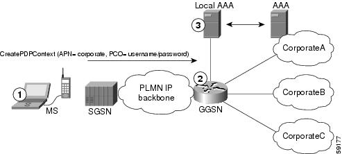
The Cisco Systems GGSN software determines the ultimate target network for the session by receiving the create PDP context request at the virtual access point and extracting the domain name to direct the packet to the appropriate real APN. The real APN is the actual destination network.
Figure 10 shows how the GGSN supports a create PDP context request from an MS processed through a virtual APN on the GGSN.
Figure 10 Virtual APN PDP Context Activation on the GGSN
Benefits of the Virtual APN Feature
The virtual APN feature provides the following benefits:
•Simplifies provisioning of APN information at the HLR and DNS servers.
•Improves scalability for support of large numbers of corporate networks, ISPs, and services.
•Increases flexibility of access point selection.
•Eases deployment of new APNs and services.
Restrictions of the virtual APN Feature
The virtual APN feature has the following restriction:
•S-CDRs and G-CDRs do not include the domain information.
Virtual APN Configuration Task List
To configure the GGSN to support virtual APN access, you must configure one or more virtual access points. You also need to configure the real access points that provide the information needed to connect to the physical networks of the external PDNs or VPNs.
In addition to the configuring the GGSN, you must also ensure proper provisioning of other GPRS network entities as appropriate to successfully implement the virtual APN feature on the GPRS network.
To configure virtual APN access on the GGSN, perform the following tasks:
•Configuring Virtual Access Points on the GGSN (Required)
•Configuring Real Access Points on the GGSN (Required)
–PDN Access Configuration Task List
–VPN Access Using VRF Configuration Task List
For a sample configuration, see the "Virtual APN Configuration Example" section.
Configuring Virtual Access Points on the GGSN
Use virtual access point types to consolidate access to multiple real target networks on the GGSN. The GGSN always uses real access points to reach an external network, so virtual access points are used in combination with real access points on the GGSN.
You can configure multiple virtual access points on the GGSN. Multiple virtual access points can be used to access the same real networks. One virtual access point can be used to access different real networks.
Note Be sure that you provision the HLR and configure the DNS server to properly correspond to the virtual APN domains that you have configured on the GGSN. For more information, see the "Configuring Other GPRS Network Entities With the Virtual APN" section.
To configure a virtual access point on the GGSN, use the following commands beginning in global configuration mode:
Note Although the Cisco IOS software allows you to configure other access point options on a virtual access point, no other access point options are applicable if they are configured.
Configuring Other GPRS Network Entities With the Virtual APN
When you configure the GGSN to support virtual APN access, be sure that you also meet any necessary requirements to properly configure other GPRS network entities to support the virtual APN implementation.
The following GPRS network entities might also require provisioning to properly implement virtual APN support:
•DHCP server—Requires configuration of the real APNs.
•DNS server—The DNS server that the SGSN uses to resolve the address of the GGSN must identify the virtual APN with the IP address of the GTP virtual template on the GGSN. If GTP SLB is implemented, then the virtual APN should be associated with the IP address of the GTP load balancing virtual server instance on the SLB router.
•HLR—Requires the name of the virtual APN in subscription data, as allowable for subscribed users.
•RADIUS server—Requires configuration of the real APNs.
•SGSN—Requires the name of the virtual APN as the default APN (as desired) when the APN is not provided in user subscription data.
Verifying the Virtual APN Configuration
This section describes how to verify that you have successfully configured virtual APN support on the GGSN, and includes the following tasks:
•Verifying the GGSN Configuration
•Verifying Reachability of the Network Through the Virtual Access Point
Verifying the GGSN Configuration
To verify that you have properly configured access points on the GGSN, use the show running-config command and the show gprs access-point commands.
Note The gprs access-point-list command first appears in the output of the show running-config command under the virtual template interface, which indicates that the gprs access point list has been configured and is associated with the virtual template. To verify your configuration of specific access points within the gprs access point list, look further down in the show output where the gprs access-point-list command appears again followed by the individual access point configurations.
Step 1 From privileged EXEC mode, use the show running-config command as shown in the following example. Verify the interface configuration and virtual and real access points as shown by the arrows:
ggsn# show running-config
Building configuration...
Current configuration : 3521 bytes
!
version 12.2
no service single-slot-reload-enable
service timestamps debug uptime
service timestamps log uptime
no service password-encryption
!
! Enable the router for GGSN services
!
service gprs ggsn
!
hostname ggsn
!
no logging buffered
logging rate-limit console 10 except errors
aaa new-model
aaa group server radius foo
server 172.18.43.7 auth-port 1645 acct-port 1646
aaa authentication ppp foo group foo
aaa authorization network foo group foo
aaa accounting network foo start-stop group foo
!
ip subnet-zero
!
!
no ip dhcp-client network-discovery
!
!
interface Loopback1
ip address 10.2.3.4 255.255.255.255
!
interface FastEthernet0/0
ip address 172.18.43.174 255.255.255.240
duplex half
!
interface FastEthernet2/0
description Gn interface
ip address 192.168.10.56 255.255.255.0
!
! Define Gi physical interfaces to real networks
!
interface Ethernet1/0
description Gi interface to corporatea.com
ip address 10.8.8.6 255.255.255.0
no ip route-cache
no ip mroute-cache
duplex half
!
interface Ethernet1/1
description Gi interface to corporateb.com
ip address 10.9.9.4 255.255.255.0
no ip route-cache
no ip mroute-cache
duplex half
!
interface Ethernet1/2
description Gi interface to corporatec.com
ip address 10.15.15.10 255.255.255.0
no ip route-cache
no ip mroute-cache
duplex half
!
interface Virtual-Template1
ip address 10.40.40.3 255.255.255.0
encapsulation gtp
gprs access-point-list gprs
!
ip default-gateway 172.18.43.161
ip kerberos source-interface any
ip classless
ip route 10.7.7.0 255.255.255.0 10.8.8.2
ip route 10.102.82.0 255.255.255.0 172.18.43.161
ip route 192.168.1.1 255.255.255.255 FastEthernet2/0
ip route 172.18.0.0 255.255.0.0 172.18.43.161
no ip http server
!
gprs access-point-list gprs
!
! Configure a virtual access point called corporate
!
access-point 1
access-point-name corporate
access-type virtual
exit
!
! Configure three real access points called corporatea.com,
! corporateb.com, and corporatec.com
!
access-point 2
access-point-name corporatea.com
access-mode non-transparent
aaa-group authentication foo
exit
!
access-point 3
access-point-name corporateb.com
exit
!
access-point 4
access-point-name corporatec.com
access-mode non-transparent
aaa-group authentication foo
exit
!
!
gprs maximum-pdp-context-allowed 90000
gprs gtp path-echo-interval 0
gprs default charging-gateway 10.15.15.1
!
radius-server host 172.18.43.7 auth-port 1645 acct-port 1646 non-standard
radius-server retransmit 3
radius-server key 7 12150415
call rsvp-sync
!
no mgcp timer receive-rtcp
!
mgcp profile default
!
!
gatekeeper
shutdown
!
end
Step 2 To view the configuration of a specific access point on the GGSN in further detail, use the show gprs access-point command and specify the index number of the access point, as shown in the following examples.
The following output shows information about a real access point:
Router# show gprs access-point 2
apn_index 2 apn_name = corporatea.com
apn_mode: non-transparent
apn-type: Real
accounting: Disable
wait_accounting: Disable
dynamic_address_pool: not configured
apn_dhcp_server: 0.0.0.0
apn_dhcp_gateway_addr: 0.0.0.0
apn_authentication_server_group: foo
apn_accounting_server_group:
apn_username: , apn_password:
subscribe_required: No
deactivate_pdp_context_on violation: No
network_activation_allowed: No
Block Foreign-MS Mode: Disable
VPN: Disable
GPRS vaccess interface: Virtual-Access1
RADIUS attribute suppress MSISDN: Disabled
RADIUS attribute suppress IMSI: Disabled
RADIUS attribute suppress SGSN Address: Disabled
RADIUS attribute suppress QOS: Disabled
number of ip_address_allocated 0
idle timer: 0
Security features
Verify mobile source addr: Enable
Verify mobile destination addr: Enable
Traffic redirection:
Mobile-to-mobile: destination 1.1.1.1
Total number of PDP in this APN :1
aggregate:
In APN: Disable
In Global: Disable
The following output shows information about a virtual access point:
Router# show gprs access-point 1
apn_index 1 apn_name = corporate
apn_mode: transparent
apn-type: Virtual
accounting: Disable
wait_accounting: Disable
dynamic_address_pool: not configured
apn_dhcp_server: 0.0.0.0
apn_dhcp_gateway_addr: 0.0.0.0
apn_authentication_server_group:
apn_accounting_server_group:
apn_username: , apn_password:
subscribe_required: No
deactivate_pdp_context_on violation: No
network_activation_allowed: No
Block Foreign-MS Mode: Disable
VPN: Disable
GPRS vaccess interface: Virtual-Access2
RADIUS attribute suppress MSISDN: Disabled
RADIUS attribute suppress IMSI: Disabled
RADIUS attribute suppress SGSN Address: Disabled
RADIUS attribute suppress QOS: Disabled
number of ip_address_allocated 0
idle timer: 0
Security features
Verify mobile source addr: Disabled
Verify mobile destination addr: Disabled
Traffic redirection:
Mobile-to-mobile:
Total number of PDP in this APN :0
aggregate:
In APN: Disable
In Global: Disable
Step 3 To view a summary of every access point that is configured on the GGSN, use the show gprs access-point all command as shown in the following example:
ggsn# show gprs access-point all
There are 4 Access-Points configured
Index Mode Access-type AccessPointName VRF Name
-----------------------------------------------------------------------
1 transparent Virtual corporate
-----------------------------------------------------------------------
2 non-transparent Real corporatea.com
-----------------------------------------------------------------------
3 transparent Real corporateb.com
-----------------------------------------------------------------------
4 non-transparent Real corporatec.com
-----------------------------------------------------------------------
Verifying Reachability of the Network Through the Virtual Access Point
To verify reachability of the real destination network through the virtual access point, you can use the same procedure described in the "Verifying Reachability of the Network Through the Access Point" section.
In addition, you should meet the following guidelines for virtual access point testing:
•When you initiate PDP context activation at the MS, be sure that the username that you specify (in the form of login@domain in the create PDP context request) corresponds to a real APN that you have configured on the GGSN.
•When you generate traffic to the network, be sure to select a host on one of the real destination networks that is configured for APN support on the GGSN.
Configuring Network-Initiated PDP Context Support on the GGSN
This section includes the following topics:
•Overview of Network-Initiated PDP Context Support
•Network-Initiated PDP Context Configuration Task List
•Verifying the Network-Initiated PDP Context Configuration
For a sample configuration, see the "Network-Initiated PDP Request Configuration Example" section.
Overview of Network-Initiated PDP Context Support
In GPRS Release 1.4 and earlier, the GGSN only supports creation of PDP contexts that are originated by an MS. As of GGSN Release 3.0, the GGSN adds support for network-initiated PDP contexts for statically configured IP addresses. This means that the GGSN supports a process for creating PDP contexts initiated by an external IP network.
When the GGSN receives a PDU destined for an MS from the IP network, it verifies whether a PDP context is already established for that MS on the GGSN. If the MS does not have an existing PDP context on the GGSN, then the GGSN issues a Send Routing Information request to the home location register (HLR). The GGSN uses a GSN that provides the necessary GPRS Tunneling Protocol (GTP)-to-Mobile Application Part (MAP) conversion to communicate with the HLR. If the HLR determines that the Send Routing Information request can be served, it sends the GGSN the address of the SGSN (through the protocol-converting GSN) that is currently serving that MS. The GGSN sends a PDU Notification Request to the SGSN serving the MS, and the SGSN requests that the MS establish the PDP context with the GGSN.
Restrictions
The GGSN supports creation of network-initiated PDP contexts with the following restrictions:
•IP addresses corresponding to the International Mobile Subscriber Identity (IMSI) of an MS must be statically configured on the GGSN using the gprs ni-pdp ip-imsi single command.
•If you are implementing VPN access through a VRF at the access point, you must configure the access point for VRF before you configure the IP to IMSI address mappings using the gprs ni-pdp ip-imsi single global configuration command. If you configure the gprs ni-pdp ip-imsi single command before you configure VRF at the access point, then the addresses that you specify become part of the global routing table and not the VRF routing table.
Network-Initiated PDP Context Configuration Task List
The GGSN supports network-initiated PDP contexts for both VPN and non-VPN networks. However, access through a VPN is preferable for greater flexibility in IP addressing and better control over security and other functions at the GGSN access point.
To configure network-initiated PDP context support on the GGSN through a VPN, perform the following tasks:
•Configuring Network-Initiated PDP Context Support at an APN (Required)
•Specifying the GSN for GTP-MAP Protocol Conversion (Required)
•Configuring the Static IP Address Mapping to IMSI (Required)
•Configuring Other Network-Initiated PDP Options (Optional)
To verify your configuration, see the "Verifying the Network-Initiated PDP Context Configuration" section.
For a sample configuration, see the "Network-Initiated PDP Request Configuration Example" section.
Configuring Network-Initiated PDP Context Support at an APN
To support network-initiated PDP context activation on the GGSN at a specific APN, you must enable network request activation at the access point.
The GGSN supports network-initiated PDP contexts at multiple VPNs. To do this, you must create an access point for each VPN that you want to support and you must configure VRF at the APN. In addition to configuring VRF at the APN, other tasks are required to complete the VRF configuration. For more information about configuring VRF support on the GGSN, see the "VPN Access Using VRF Configuration Task List" section.
To configure network-initiated PDP context support at an APN, use the following commands beginning in global configuration mode:
For information about other access point configuration options, see the "Configuring the GPRS Access Point List on the GGSN" section.
Specifying the GSN for GTP-MAP Protocol Conversion
To specify the address of the GSN for GTP-MAP protocol conversion, use the following command in global configuration mode:
Configuring the Static IP Address Mapping to IMSI
The GGSN supports network-initiated PDP context requests from both a VPN or other intranet using statically configured address mappings only.
When you configure the static IP address mapping to IMSI, you must specify the proper APN number where you have enabled the network-request-activation command.
To configure the static IP address mapping to the IMSI of an MS, use the following command in global configuration mode:
Configuring Other Network-Initiated PDP Options
To configure other network-initiated PDP context options on the GGSN, use the following commands beginning in global configuration mode:
Verifying the Network-Initiated PDP Context Configuration
This section describes how to verify that you have sucessfully configured the GGSN for network-initiated PDP context support, and includes the following tasks:
•Verifying the GGSN Configuration
•Verifying Reachability of the MS Using Network-Initiated PDP Request
Verifying the GGSN Configuration
To verify that you have properly configured the GGSN for network-initiated PDP context support, use the show running-config and show gprs access-point commands.
Step 1 From privileged EXEC mode, use the show running-config command as shown in the following example. Verify the access point and global configuration values as shown in bold:
ggsn# show running-config
Building configuration...
Current configuration : 3521 bytes
!
version 12.2
no service single-slot-reload-enable
service timestamps debug uptime
service timestamps log uptime
no service password-encryption
service gprs ggsn
!
hostname ggsn
!
no logging buffered
logging rate-limit console 10 except errors
aaa new-model
aaa group server radius foo
server 172.18.43.7 auth-port 1645 acct-port 1646
aaa authentication ppp foo group foo
aaa authorization network foo group foo
aaa accounting exec default start-stop group foo
aaa accounting network foo start-stop group foo
!
ip vrf vpn1
rd 100:1
!
ip subnet-zero
!
ip cef
!
no ip dhcp-client network-discovery
!
!
interface Loopback1
ip address 10.2.3.4 255.255.255.255
!
interface FastEthernet0/0
ip address 172.18.43.174 255.255.255.240
duplex half
!
interface Ethernet1/0
description Gi interface to gprt.cisco.com
ip address 10.8.8.6 255.255.255.0
ip vrf forwarding vpn1
no ip route-cache
no ip mroute-cache
duplex half
!
interface Ethernet1/1
description Gi interface to gprs.cisco.com
ip address 10.9.9.4 255.255.255.0
no ip route-cache
no ip mroute-cache
duplex half
!
interface Ethernet1/2
ip address 10.15.15.10 255.255.255.0
duplex half
!
interface Virtual-Template1
ip address 10.40.40.3 255.255.255.0
encapsulation gtp
gprs access-point-list gprs
!
ip default-gateway 172.18.43.161
ip kerberos source-interface any
ip classless
ip route 10.7.7.0 255.255.255.0 10.8.8.2
ip route 10.102.82.0 255.255.255.0 172.18.43.161
ip route 192.168.0.0 255.255.0.0 172.18.43.161
ip route 172.18.0.0 255.255.0.0 172.18.43.161
no ip http server
!
. . .
!
For network-initiated PDP context support at a VPN, verify that you have enabled network-initiated PDP context support at the APN and have properly configured the APNs for VPN access as shown in bold:
!
. . .
gprs access-point-list gprs
!
access-point 1
access-point-name gprs.cisco.com
access-mode non-transparent
aaa-group authentication foo
network-request-activation
exit
!
access-point 2
access-point-name gprt.cisco.com
network-request-activation
vrf vpn1
exit
!
access-point 3
access-point-name gpru.cisco.com
access-mode non-transparent
aaa-group authentication foo
exit
!
gprs maximum-pdp-context-allowed 90000
gprs gtp path-echo-interval 0
gprs default charging-gateway 10.15.15.1
gprs gtp ip udp ignore checksum
!
. . .
!
Verify that you have configured the protocol-converting SGSN and configured the IP address-to-IMSI mappings for each of the MSs that you want to support, as shown in bold:
!
. . .
gprs default map-converting-gsn 10.7.7.1
gprs ni-pdp ip-imsi single 1 10.100.1.1 11111111111111F1
gprs ni-pdp ip-imsi single 2 172.31.1.2 11111111111111F2
gprs ni-pdp ip-imsi single 2 172.31.1.3 11111111111111F3
!
!
radius-server host 172.18.43.7 auth-port 1645 acct-port 1646 non-standard
radius-server retransmit 3
radius-server key 7 12150415
call rsvp-sync
!
no mgcp timer receive-rtcp
!
mgcp profile default
!
!
gatekeeper
shutdown
!
end
Step 2 From privileged EXEC mode, use the show gprs access-point command and verify that the network_activation_allowed output field contains the value Yes, as shown in the following example:
Router# show gprs access-point 1
apn_index 1 apn_name = gprs.cisco.com
apn_mode: non-transparent
apn-type: Real
accounting: Disable
wait_accounting: Disable
dynamic_address_pool: not configured
apn_dhcp_server: 0.0.0.0
apn_dhcp_gateway_addr: 0.0.0.0
apn_authentication_server_group: foo
apn_accounting_server_group:
apn_username: , apn_password:
subscribe_required: No
deactivate_pdp_context_on violation: No
network_activation_allowed: Yes
Block Foreign-MS Mode: Disable
VPN: Disable
GPRS vaccess interface: Virtual-Access1
RADIUS attribute suppress MSISDN: Disabled
RADIUS attribute suppress IMSI: Disabled
RADIUS attribute suppress SGSN Address: Disabled
RADIUS attribute suppress QOS: Disabled
number of ip_address_allocated 0
idle timer: 0
Security features
Verify mobile source addr: Disable
Verify mobile destination addr: Disable
Traffic redirection:
Mobile-to-mobile: destination 1.1.1.1
Total number of PDP in this APN :0
aggregate:
In APN: Disable
In Global: Disable
Verifying Reachability of the MS Using Network-Initiated PDP Request
To verify that you can reach the MS from the PDN, perform the following steps:
Step 1 From the PDN side of the IP network, generate traffic to the MS. To do this, you can use the ping command with the IP address of the MS.
In the configuration example shown in Figure 12, you could issue ping 10.100.1.1, ping 172.31.1.2, or ping 172.31.1.3.
Step 2 From privileged EXEC mode on the GGSN, use the show gprs gtp statistics command and verify the number of rejected and created network PDP contexts (in the ntwk_init_pdp_act_rej and total ntwkInit created pdp output fields).
The following example shows 1 successful network-initiated PDP context:
Router# show gprs gtp statistics
GPRS GTP Statistics:
version_not_support 0 msg_too_short 0
unknown_msg 0 unexpected_sig_msg 1
unexpected_data_msg 0 mandatory_ie_missing 0
mandatory_ie_incorrect 0 optional_ie_invalid 0
ie_unknown 0 ie_out_of_order 0
ie_unexpected 0 ie_duplicated 0
optional_ie_incorrect 0 pdp_activation_rejected 0
path_failure 0 total_dropped 0
signalling_msg_dropped 0 data_msg_dropped 0
no_resource 0 get_pak_buffer_failure 0
rcv_signalling_msg 4 snd_signalling_msg 8
rcv_pdu_msg 0 snd_pdu_msg 1
rcv_pdu_bytes 0 snd_pdu_bytes 100
total created_pdp 1 total deleted_pdp 0
total created_ppp_pdp 0
ppp_regen_pending 0 ppp_regen_pending_peak 0
ppp_regen_total_drop 0 ppp_regen_no_resource 0
ntwk_init_pdp_act_rej 0 total ntwkInit created pdp 1
Step 3 Use the show gprs gtp pdp-context tid command and verify that the ntwk_init_pdp output field contains the value 1, as shown in the following example.
Note To find the TID of a PDP context for a particular MS, use the show gprs gtp pdp-context ms-address command.
GGSN_1# show gprs gtp pdp-context tid 81726354453647F2
TID MS Addr Source SGSN Addr APN
81726354453647F2 10.100.1.1 Static 10.7.7.1 gprs.cisco.com
current time :Mar 18 2002 11:24:36
user_name (IMSI): 182736455463742 MS address: 10.100.1.1
MS International PSTN/ISDN Number (MSISDN):ABC
sgsn_addr_signal:10.8.8.1 ggsn_addr_signal:10.8.0.1
signal_sequence: 0 seq_tpdu_up: 0
seq_tpdu_down: 0
upstream_signal_flow: 1 upstream_data_flow: 2
downstream_signal_flow:14 downstream_data_flow:12
RAupdate_flow: 0
pdp_create_time: Mar 18 2002 09:58:39
last_access_time: Mar 18 2002 09:58:39
mnrgflag: 0 tos mask map:00
gtp pdp idle time:72
gprs qos_req:091101 canonical Qos class(req.):01
gprs qos_neg:25131F canonical Qos class(neg.):01
effective bandwidth:0.0
rcv_byte_count: 0 rcv_pkt_count: 0
send_byte_count: 0 send_pkt_count: 0
cef_up_pkt: 0 cef_up_byte: 0
cef_down_pkt: 0 cef_down_byte: 0
charging_id: 29160231
pdp reference count:2
primary dns: 2.2.2.2
secondary dns: 4.4.4.4
primary nbns: 3.3.3.3
secondary nbns: 5.5.5.5
ntwk_init_pdp: 1
** Network Init Information **
MNRG Flag: 0 PDU Discard Flag: 0
SGSN Addr: 172.16.44.1 NIP State: NIP_STATE_WAIT_PDP_ACTIVATION
Buf.Bytes: 500
Blocking Access to the GGSN by Foreign Mobile Stations
This section describes how to restrict access to the GGSN by mobile stations outside of their home PLMN. It includes the following topics:
•Overview of Blocking Foreign Mobile Stations
•Blocking Foreign Mobile Stations Configuration Task List
•Blocking Access by Foreign Mobile Stations Configuration Example
Overview of Blocking Foreign Mobile Stations
The GGSN allows you to block access by mobile stations who are outside of the PLMN. When you enable blocking of foreign mobile stations, the GGSN determines if an MS is inside or outside of the PLMN based on the mobile country code (MCC) and mobile network code (MNC). You must specify the MCC and MNC codes on the GGSN to properly configure the home public land mobile network (HPLMN) values.
When you enable the blocking foreign MS access feature on the access point, then when the GGSN receives a GTP create PDP context request message, the GGSN compares the MCC and MNC in the TID against the home operator codes that you configure on the GGSN. If the MS mobile operator code fails the matching criteria on the GGSN, then the GGSN rejects the create PDP context request message.
Blocking Foreign Mobile Stations Configuration Task List
To implement blocking of foreign mobile stations on the GGSN, you must enable the function and specify the supporting criteria for determining whether an MS is outside of its home PLMN.
To configure blocking of foreign mobile stations on the GGSN, perform the following tasks:
•Enabling Blocking of Foreign Mobile Stations on the GGSN (Required)
•Configuring the MCC and MNC Values (Required)
•Verifying the Blocking of Foreign Mobile Stations Configuration
Enabling Blocking of Foreign Mobile Stations on the GGSN
To enable the GGSN to block foreign mobile stations from establishing PDP contexts, use the following command in global configuration mode:
|
|
|
|---|---|
Router(config-access-point)# block-foreign-ms |
Restricts GGSN access based on the mobile user's HPLMN. |
Configuring the MCC and MNC Values
To configure the MCC and MNC values that the GGSN uses to determine if a request is from a roaming MS, use the following command in global configuration mode:
Verifying the Blocking of Foreign Mobile Stations Configuration
This section describes how you can verify the blocking of foreign mobile stations configuration on the GGSN. It includes the following topics:
•Verifying Blocking of Foreign Mobile Stations at an Access Point
•Verifying the MCC and MNC Configuration on the GGSN
Verifying Blocking of Foreign Mobile Stations at an Access Point
To verify whether the GGSN is configured to support blocking of foreign mobile stations at a particular access point, use the show gprs access-point command. Observe the value of the Block Foreign-MS Mode output field as shown in bold in the following example:
Router# show gprs access-point 1
apn_index 1 apn_name = gprs.corporate.com
apn_mode: transparent
apn-type: Real
accounting: Disable
wait_accounting: Disable
dynamic_address_pool: dhcp-proxy-client
apn_dhcp_server: 10.99.100.5
apn_dhcp_gateway_addr: 10.27.1.1
apn_authentication_server_group: foo
apn_accounting_server_group: foo1
apn_username: , apn_password:
subscribe_required: No
deactivate_pdp_context_on violation: Yes
network_activation_allowed: Yes
Block Foreign-MS Mode: Enable
VPN: Enable (VRF Name : vpn1)
GPRS vaccess interface: Virtual-Access2
RADIUS attribute suppress MSISDN: Disable
RADIUS attribute suppress IMSI: Disable
RADIUS attribute suppress SGSN Address: Disable
RADIUS attribute suppress QOS: Disable
number of ip_address_allocated 0
idle timer: 0
Security features
Verify mobile source addr: Disable
Verify mobile destination addr: Disable
Traffic redirection:
Mobile-to-mobile: destination 1.1.1.1
Total number of PDP in this APN :0
aggregate:
In APN: Disable
In Global: Disable
Verifying the MCC and MNC Configuration on the GGSN
To verify the configuration elements that the GGSN uses as matching criteria to determine whether a request is coming from a foreign mobile station, use the show gprs gtp parameters privileged EXEC command. Observe the values of the output fields shown in bold in the following example. The example shows that the GGSN is configured for the USA country code (310) and for the Bell South network code (15):
Router# show gprs gtp parameters
GTP path echo interval = 60
GTP signal max wait time T3_response = 1
GTP max retry N3_request = 5
GTP dynamic echo-timer minimum = 5
GTP dynamic echo-timer smooth factor = 2
GTP buffer size for receiving N3_buffer = 8192
GTP max pdp context = 45000
GPRS MCC Code = 310
GPRS MNC Code = 15
Note For a reference table of some of the established MCC and MNC codes, refer to the Appendix of the Cisco IOS Mobile Wireless Command Reference.
Controlling Access to the GGSN by MSs with Duplicate IP Addresses
An MS can not have the same IP address as another GPRS network entity. You can configure the GGSN to reserve certain IP address ranges for use by the GPRS network, and to disallow them from use by an MS.
During a create PDP context request, the GGSN verifies whether the IP address of an MS falls within the specified excluded range. If there is an overlap of the MS IP address with an excluded range, then the PDP context request is rejected. This measure prevents duplicate IP addressing in the network.
You can configure up to 100 IP address ranges. A range can be one or more addresses. However, you can configure only one IP address range per command entry. To exclude a single IP address, you can repeat the IP address in the start-ip and end-ip arguments. IP addresses are 32-bit values.
To reserve IP address ranges for use by the GPRS network and block their use by an MS, use the following command in global configuration mode:
|
|
|
|---|---|
Router(config)# gprs ms-address exclude-range start-ip end-ip |
Specifies the IP address ranges used by the GPRS network, and thereby excluded from the MS IP address range. |
Configuration Examples
This section includes the following configuration examples for configuring different types of network access to the GGSN:
•Access Point List Configuration Example
•VRF Tunnel Configuration Example
•Virtual APN Configuration Example
•Network-Initiated PDP Request Configuration Example
•Blocking Access by Foreign Mobile Stations Configuration Example
•Duplicate IP Address Protection Configuration Example
Static Route to SGSN Example
The following example shows how to configure a static route from a physical interface on the GGSN to the SGSN.
Notice the following areas in the GGSN configuration shown in this example:
•FastEthernet0/0 is the physical interface to the SGSN, which is known as the Gn interface.
•In this example, the SGSN is located at IP address 192.168.1.1. Using the ip route command, a static route is configured to the SGSN located at 192.168.1.1 from the FastEthernet0/0 interface on the GGSN.
GGSN Configuration
! Configure Gn interface on GGSN to communicate with SGSN
!
interface FastEthernet0/0
ip address 10.0.0.2 255.0.0.0
no ip directed-broadcast
no ip route-cache
no ip mroute-cache
no keepalive
!
ip route 192.168.1.1 255.255.255.255 FastEthernet0/0
Note For the SGSN to successfully communicate with the GGSN, the SGSN must configure a static route, or be able to dynamically route to the IP address used by the GGSN virtual template.
Access Point List Configuration Example
The following example shows a portion of the GGSN configuration for a GPRS access point list:
!
interface virtual-template 1
ip address 10.15.10.1 255.255.255.0
no ip directed-broadcast
encapsulation gtp
gprs access-point-list abc
!
! Defines a GPRS access point list named abc
! with 3 access points
!
gprs access-point-list abc
access-point 1
access-point-name gprs.pdn1.com
ip-address-pool dhcp-proxy-client
dhcp-server 10.102.100.3
dhcp-gateway-address 10.30.30.30
exit
!
access-point 2
access-point-name gprs.pdn2.com
ip-address-pool dhcp-proxy-client
dhcp-server 10.60.0.1
dhcp-gateway-address 10.27.27.27
exit
!
access-point 3
access-point-name www.pdn3.com
access-mode non-transparent
dhcp-gateway-address 10.25.25.25
aaa-group authentication foo
exit
!
. . .
VRF Tunnel Configuration Example
The following example shows a partial configuration for a virtual private network named "vpn1" using VRF:
! Configure a VRF routing table
! and define an identifier
!
ip vrf vpn1
rd 100:1
!
! Enable CEF switching
!
ip cef
!
interface Loopback101
ip address 10.14.101.1 255.255.255.255
!
! Configure a tunnel interface
! to a private network using VRF
!
interface Tunnel1
ip vrf forwarding vpn1
ip address 10.1.101.1 255.255.255.0
tunnel source 10.14.101.1
tunnel destination 10.13.101.1
!
! Configure OSPF routing using VRF
!
router ospf 101 vrf vpn1
log-adjacency-changes
redistribute static subnets
network 10.1.101.0 0.0.0.255 area 0
!
! Configure VRF at the access point
!
gprs access-point-list gprs
access-point 1
access-point-name gprs.cisco.com
vrf vpn1
exit
Virtual APN Configuration Example
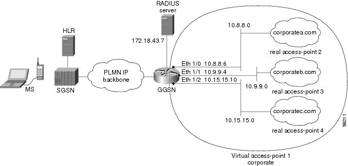
The following example shows a GGSN that is configured for a virtual APN access point that serves as the focal connection for three different real corporate networks.
Notice the following areas in the GGSN configuration shown in this example:
•Three physical interfaces (Gi interfaces) are defined to establish access to the real corporate networks: Ethernet 1/0, Ethernet 1/1, and Ethernet 1/2.
•Four access points are configured:
–Access point 1 is configured as the virtual access point with an APN called corporate. No other configuration options are applicable at the virtual access point. The "corporate" virtual APN is the APN that is provisioned at the HLR and DNS server.
–Access points 2, 3, and 4 are configured to the real network domains: corporatea.com, corporateb.com, and corporatec.com. The real network domains are indicated in the PCO of the PDP context request.
Figure 11 Virtual APN Configuration Example
GGSN Configuration
!
version 12.2
no service single-slot-reload-enable
service timestamps debug uptime
service timestamps log uptime
no service password-encryption
!
! Enable the router for GGSN services
!
service gprs ggsn
!
hostname ggsn
!
no logging buffered
logging rate-limit console 10 except errors
aaa new-model
aaa group server radius foo
server 172.18.43.7 auth-port 1645 acct-port 1646
aaa authentication ppp foo group foo
aaa accounting network foo start-stop group foo
!
ip subnet-zero
!
!
no ip dhcp-client network-discovery
!
!
interface Loopback1
ip address 10.2.3.4 255.255.255.255
!
interface FastEthernet0/0
ip address 172.18.43.174 255.255.255.240
duplex half
!
interface FastEthernet2/0
description Gn interface
ip address 192.168.10.56 255.255.255.0
!
! Define Gi physical interfaces to real networks
!
interface Ethernet1/0
description Gi interface to corporatea.com
ip address 10.8.8.6 255.255.255.0
no ip route-cache
no ip mroute-cache
duplex half
!
interface Ethernet1/1
description Gi interface to corporateb.com
ip address 10.9.9.4 255.255.255.0
no ip route-cache
no ip mroute-cache
duplex half
!
interface Ethernet1/2
description Gi interface to corporatec.com
ip address 10.15.15.10 255.255.255.0
no ip route-cache
no ip mroute-cache
duplex half
!
interface Virtual-Template1
ip address 10.40.40.3 255.255.255.0
encapsulation gtp
gprs access-point-list gprs
!
ip default-gateway 172.18.43.161
ip kerberos source-interface any
ip classless
ip route 10.7.7.0 255.255.255.0 10.8.8.2
ip route 10.21.21.0 255.255.255.0 Ethernet1/1
ip route 10.102.82.0 255.255.255.0 172.18.43.161
ip route 192.168.1.1 255.255.255.255 FastEthernet2/0
ip route 172.18.0.0 255.255.0.0 172.18.43.161
no ip http server
!
gprs access-point-list gprs
!
! Configure a virtual access point called corporate
!
access-point 1
access-point-name corporate
access-type virtual
exit
!
! Configure three real access points called corporatea.com,
! corporateb.com, and corporatec.com
!
access-point 2
access-point-name corporatea.com
access-mode non-transparent
aaa-group authentication foo
exit
access-point 3
access-point-name corporateb.com
access-mode transparent
ip-address-pool dhcp-client
dhcp-server 10.21.21.1
exit
!
access-point 4
access-point-name corporatec.com
access-mode non-transparent
aaa-group authentication foo
exit
!
!
gprs maximum-pdp-context-allowed 90000
gprs gtp path-echo-interval 0
gprs default charging-gateway 10.15.15.1
!
radius-server host 172.18.43.7 auth-port 1645 acct-port 1646 non-standard
radius-server retransmit 3
radius-server key 7 12150415
call rsvp-sync
!
no mgcp timer receive-rtcp
!
mgcp profile default
!
!
gatekeeper
shutdown
!
end
Network-Initiated PDP Request Configuration Example
The following example shows a GGSN that is configured to support network initiated PDP contexts at a VPN on access point 1 for statically configured IP addresses. This example also shows support of network-initiated PDP contexts for MSs with an IP address of 172.31.1.2 and 172.31.1.3, which have been statically configured on the GGSN through access point 2.
Figure 12 Network Initiated PDP Request Configuration Example
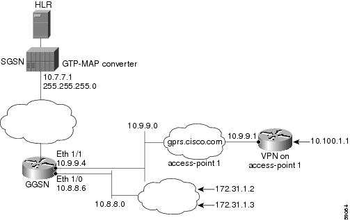
GGSN Configuration
!
version 12.2
no service single-slot-reload-enable
service timestamps debug uptime
service timestamps log uptime
no service password-encryption
!
! Enable the router for GGSN services
!
service gprs ggsn
!
hostname ggsn
!
no logging buffered
logging rate-limit console 10 except errors
!
aaa new-model
!
aaa group server radius foo
server 172.18.43.7 auth-port 1645 acct-port 1646
aaa authentication ppp foo group foo
aaa accounting network foo start-stop group foo
!
! Configure a VRF routing table
! and define an identifier
!
ip vrf vpn1
rd 100:1
!
ip subnet-zero
!
no ip dhcp-client network-discovery
!
!
! Enable CEF switching
!
ip cef
!
interface Loopback1
ip address 10.2.3.4 255.255.255.255
!
interface FastEthernet0/0
ip address 172.18.43.174 255.255.255.240
duplex half
!
interface Ethernet1/0
description Gi interface to gprt.cisco.com
ip address 10.8.8.6 255.255.255.0
no ip route-cache
no ip mroute-cache
duplex half
!
! Configure VRF at the interface
!
interface Ethernet1/1
description Gi interface to gprs.cisco.com
ip address 10.9.9.4 255.255.255.0
ip vrf forwarding vpn1
no ip route-cache
no ip mroute-cache
duplex half
!
interface Ethernet1/2
ip address 10.15.15.10 255.255.255.0
duplex half
!
interface Virtual-Template1
ip address 10.40.40.3 255.255.255.0
encapsulation gtp
gprs access-point-list gprs
!
ip default-gateway 172.18.43.161
ip kerberos source-interface any
ip classless
ip route 10.7.7.0 255.255.255.0 10.8.8.2
ip route 10.102.82.0 255.255.255.0 172.18.43.161
ip route 192.168.0.0 255.255.0.0 172.18.43.161
ip route 172.18.0.0 255.255.0.0 172.18.43.161
no ip http server
!
gprs access-point-list gprs
!
! Configure an access point for gprs.cisco.com
! and enable network initiated PDP context support
! for a VPN
!
access-point 1
access-point-name gprs.cisco.com
aaa-group authentication foo
!
! Enable network initiated PDP context support
!
network-request-activation
!
! Configure VRF at the access point
!
vrf vpn1
exit
!
! Configure an access point for gprt.cisco.com
! and enable network-initiated PDP context support
!
access-point 2
access-point-name gprt.cisco.com
network-request-activation
exit
!
access-point 3
access-point-name gpru.cisco.com
access-mode non-transparent
aaa-group authentication foo
exit
!
!
gprs maximum-pdp-context-allowed 90000
gprs gtp path-echo-interval 0
gprs default charging-gateway 10.15.15.1
gprs gtp ip udp ignore checksum
!
! Configure the IP address of the SGSN to perform GTP-to-MAP and
! MAP-to-GTP conversion between the HLR and GGSN
!
gprs default map-converting-gsn 10.7.7.1
!
! Configure a static IP address to IMSI mapping for each MS
!
gprs ni-pdp ip-imsi single 1 10.100.1.1 11111111111111F1
gprs ni-pdp ip-imsi single 2 172.31.1.2 11111111111111F2
gprs ni-pdp ip-imsi single 2 172.31.1.3 11111111111111F3
!
!
radius-server host 172.18.43.7 auth-port 1645 acct-port 1646 non-standard
radius-server retransmit 3
radius-server key 7 12150415
call rsvp-sync
!
no mgcp timer receive-rtcp
!
mgcp profile default
!
!
gatekeeper
shutdown
!
end
Blocking Access by Foreign Mobile Stations Configuration Example
The following example shows a partial configuration where access point 100 blocks access by foreign mobile stations:
!
version 12.2
no service single-slot-reload-enable
service timestamps debug uptime
service timestamps log uptime
no service password-encryption
!
! Enables the router for GGSN services
!
service gprs ggsn
!
hostname ggsn
!
gprs access-point-list gprs
!
access-point 100
access-point-name blocking
!
! Enables blocking of MS to APN 100
! that are outside ! of the PLMN
!
block-foreign-ms
exit
!
. . .
!
! Configures the MCC and MNC codes
!
gprs mcc 123 mnc 456
Duplicate IP Address Protection Configuration Example
The following example shows a partial configuration that specifies three different sets of IP address ranges used by the GPRS network (which are thereby excluded from the MS IP address range):
gprs ms-address exclude-range 10.0.0.1 10.20.40.50
gprs ms-address exclude-range 172.16.150.200 172.30.200.255
gprs ms-address exclude-range 192.168.100.100 192.168.200.255
 Feedback