Configuring AAL2 and AAL5 for the High Performance ATM Advanced Integration Module on the Cisco 2600 Series
Available Languages
Table Of Contents
Supported Standards, MIBs, and RFCs
Configuring ATM Interfaces to Support Voice Traffic
Preparing to Configure Voice Dial Peers
Creating a Peer Configuration Table
Configuring Cisco-Trunk Permanent Calls
Verifying the Voice Connection
Configuring ATM for AAL2 Voice
Configuring Call Admission Control for AAL2 Voice
Configuring Subcell Multiplexing for AAL2 Voice
Configuring Dial Peers to Support AAL2
Configuring AAL2-Trunk Permanent Calls
Sample Configuration for VoATM at AAL5
Sample Configuration for VoATM at AAL2
Cisco 2600 Configuration at End A
Cisco 2600 Configuration at End B
Configuring AAL2 and AAL5 for the High Performance ATM Advanced Integration Module on the Cisco 2600 Series
Feature History
12.2(2)XA
The High Performance ATM Advanced Integration Module was introduced for the Cisco 2600 series.
This feature module describes the software functions of the High Performance ATM Advanced Integration Module (AIM) feature, which allows for ATM Adaptation Layer 2 (AAL2) and ATM Adaptation Layer 5 (AAL5) on the Cisco 2600 series. It includes information on the benefits of the new feature, supported platforms, related documents, and so on.
This document includes the following sections:
Feature Overview
The High Performance ATM AIM offers a cost-effective solution for supporting low-speed ATM WAN connections on the Cisco 2600 family of products. This feature enables the Cisco 2600 series to carry voice and data traffic over ATM networks using AAL2 and AAL5 without a dedicated ATM network module. AAL2 and AAL5 are the most bandwidth-efficient standards-based trunking methods for transporting compressed voice, voice-band data, circuit-mode data, and frame-mode data over ATM infrastructures. This feature provides a cost-effective, low-density ATM T1 or E1 solution for the Cisco 2600 series.
The High Performance ATM AIM helps service providers take advantage of the inherent quality of service (QoS) features of ATM multiservice applications. Transparent LAN services allow for the connection to separate sites at native LAN speeds, without requiring that the end user be familiar with ATM protocols. Frame Relay network expansion allows enterprise customers to take advantage of ATM's faster transmission speeds by leveraging core ATM switches linked to Frame Relay switches at the edge.
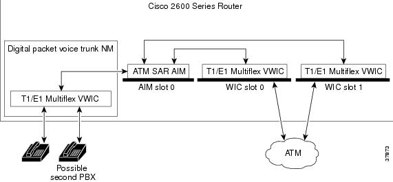
The High Performance ATM AIM is installed into an internal AIM slot. All Cisco 2600 routers support one internal AIM slot that connects to both the Cisco 2600's main system bus and a secondary time-division multiplexing (TDM) bus running between the WAN interface card (WIC) slots and network module slot.
Cisco 2600 routers have two WIC slots. When a High Performance ATM AIM is installed in a Cisco 2600 series router that has one 2-port T1/E1 Multiflex Voice/WAN (VWIC) in a WIC slot, the AIM card allows the router to provide a maximum of two separate ATM WAN interfaces at a DS1 or E1 rate. With a second 2-port VWIC, four separate ATM WAN interfaces are available.
To provide voice over ATM, the Cisco 2600 must have voice port capabilities provided by a digital packet voice trunk network module with a T1/E1 Multiflex VWIC. When also equipped with a High Performance ATM AIM, the router terminates up to 60 voice calls over T1 or E1 using AAL2.
Figure 1 Cisco 2600 Router with High Performance ATM AIM
Benefits
The High Performance ATM AIM provides the following improvements to the Cisco 2600 series' capabilities:
•
Cisco 2600 series access to AAL2 and AAL5 capabilities across the WAN
•
•
•
•
•
•
•
Restrictions
•
•
•
•
•
•
Related Documents
•
•
•
•
Supported Platforms
Cisco 2600 series
Supported Standards, MIBs, and RFCs
Standards
No new or modified standards are supported by this feature.
MIBs
No new or modified MIBs are supported by this feature. The Chassis MIB has been modified to support the High Performance ATM AIM.
For descriptions of supported MIBs and how to use MIBs, seethe Cisco web site on CCO at http://www.cisco.com/public/sw-center/netmgmt/cmtk/mibs.shtml.
RFCs
No new or modified RFCs are supported by this feature.
Prerequisites
Before you can configure your router to use the High Performance ATM AIM, complete these tasks:
•
•
•
Cisco IOS Wide-Area Networking Configuration Guide, Release 12.2.•
•
•
•
After you have analyzed your dial plan and decided how to integrate it into your existing ATM network, you are ready to configure your network devices to support the High Performance ATM AIM.
Configuration Tasks
Software configuration for a Cisco 2600 series router with the High Performance ATM AIM feature involves:
–
–
–
–
–
–
–
–
–
Configuring ATM for AAL5

Note
Configuring the Cisco 2600 series to support VoATM for AAL5 encapsulation involves the following:
•
•
•
•
Configuring ATM Interfaces to Support Voice Traffic
This section describes the preliminary ATM configuration tasks necessary to support VoATM.
Note
To configure the Cisco 2600 series to support VoATM, use the following commands beginning in global configuration mode:
Note
Preparing to Configure Voice Dial Peers
After you have analyzed your dial plan and decided how to integrate it into your existing network, you are ready to configure your network devices to support VoATM. The actual configuration procedure depends on the topology of your voice network.

Timesaver
Creating a Peer Configuration Table
There is specific information relative to each dial peer that you must identify before you can configure VoATM. One way to do this is to create a peer configuration table.
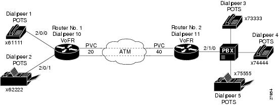
Figure 2 shows a diagram of a small voice network in which Router 1, with ATM virtual circuit 20, connects a small sales branch office to the main office through Router 2. There are only two devices in the sales branch office that need to be established as dial peers: a basic telephone and a fax machine. Router 2, with an ATM virtual circuit of 40, is the primary gateway to the main office; as such, it needs to be connected to the company's PBX. There are three basic telephones connected to the PBX that need to be established as dial peers in the main office.
Table 1 shows the peer configuration table for the example illustrated in Figure 2.
Figure 2 Sample VoATM Network
The dial plan shown in lists a simple dial-peer configuration table with no special configuration for how you forward or play out excess digits. For more information on other options for designing your dial plan and configuring your dial peers to connect with PBXs, see the Cisco IOS Voice, Video, and Fax Configuration Guide, Release 12.2.
Configuring Dial Peers
Dial peers describe the entities to and from which a call leg is established. Dial-peer configuration tasks define the address or set of addresses serviced by that dial peer and the call parameters required to establish a call leg to and from that dial peer.
Two different kinds of dial peers are used for this procedure:
•
•
POTS dial peers associate a telephone number with a particular voice port, so that incoming calls for that telephone number can be received. VoATM dial peers point to specific voice-network devices (by associating destination telephone numbers with a specific ATM virtual circuit), so that outgoing calls can be placed. Both POTS and VoATM dial peers are required if you want to send and receive calls using VoATM.
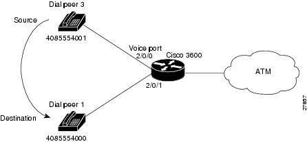
Establishing two-way communication with VoATM requires establishing a specific voice connection between two defined endpoints. As shown in Figure 3, for outgoing calls (from the perspective of POTS dial peer 1), the POTS dial peer establishes the source (the originating telephone number and voice port) of the call. The VoATM dial peer establishes the destination by associating the destination phone number with a specific ATM virtual circuit.
Figure 3 Calls from the Perspective of Router No. 1
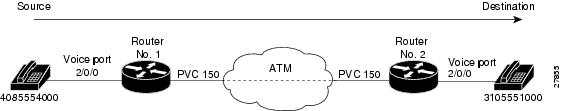
In the example, the destination pattern string14085554000 maps to a U.S. phone number 555-4000, with the digit 1 plus the area code (408) preceding the number. When configuring the destination pattern, set the dial string to match the local dial conventions.
To complete the two-way communications loop, configure VoATM dial peer 2 as shown in Figure 4.
Figure 4 Calls from the Perspective of Router No. 2
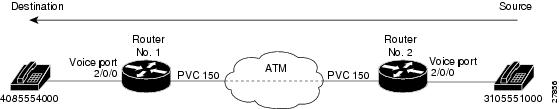
The only exception is when both POTS dial peers are connected to the same router, as shown in Figure 5. In this circumstance, because both dial peers share the same destination IP address, you do not need to configure a VoATM dial peer.
Figure 5 Communication Between Dial Peers Sharing the Same Router
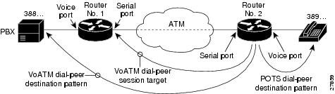
When configuring dial peers, you need to understand the relationship between the destination pattern and the session target. The destination pattern represents the pattern for the device at the voice connection endpoint, such as a telephone or a PBX. The session target represents the serial port on the peer router at the other end of the ATM connection. Figure 6 and Figure 7 show the relationship between the destination pattern and the session target, as seen from the perspective of both routers in a VoATM configuration.
Figure 6 Relationship Between the Destination Pattern and Session Target from the Perspective of Router No.1
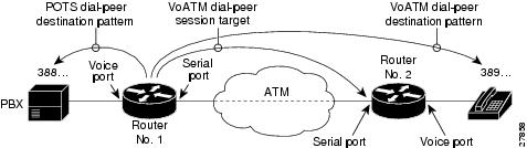
Figure 7 Relationship Between the Destination Pattern and Session Target from the Perspective of Router No.2
Configuring POTS Dial Peers
To configure a POTS dial peer, identify the peer (by assigning it a unique tag number), define its telephone number, and associate it with a voice port through which calls can be established. Under most circumstances, the default values for the remaining dial-peer configuration commands are sufficient to establish connections.
To configure POTS peers, use the following commands beginning in global configuration mode:
To configure additional POTS dial peers, repeat the previous steps.
Configuring VoATM Dial Peers
To configure a VoATM dial peer, you need to uniquely identify the peer by assigning it a unique tag number and define the outgoing serial port number and the virtual circuit number.
To configure VoATM dial peers, use the following commands beginning in global configuration mode:
To configure additional VoATM dial peers, repeat the previous steps.
Configuring Dial Peer Hunting
After you have configured dial peers, you can configure how the router performs dial peer hunting functions. To configure the dial peer hunting behavior on the router, perform the following steps beginning in global configuration mode:
If using dial peer hunting, there may be situations when you want to disable dial-peer hunting on a specific dial peer. To disable dial-peer hunting on a dial peer, use the following commands beginning in global configuration mode:
To reenable dial-peer hunting on a dial peer, enter the no huntstop command.
Configuring Cisco-Trunk Permanent Calls
To configure Cisco-trunk permanent calls on a Cisco 2600 series router for VoATM, use the following commands from global configuration mode:
Note
Verifying the Voice Connection
Verify that the voice connection is working by doing the following:
•
•
You can check the validity of your dial-peer and voice-port configuration by performing the following tasks:
•
•
•
•
Troubleshooting Tips
If you are having trouble connecting a call and you suspect the problem is associated with the dial-peer configuration, you can try to resolve the problem by performing the following tasks:
•
•
•
Configuring ATM for AAL2
To configure the High Performance ATM AIM for AAL2, complete the following tasks, as required:
•
•
•
•
•
Note
Configuring ATM for AAL2 Voice
This section describes the ATM configuration tasks necessary to support VoATM using AAL2. The commands and procedures in this section are specific to the Cisco 2600 series.
Note
You must perform the VoATM configuration on the Cisco 2600 series at both ends of the ATM link.
To configure a Cisco 2600 series router to support VoATM on a T1/E1 trunk, complete the following steps, beginning in global configuration mode:
Note
Configuring Call Admission Control for AAL2 Voice
This section describes the configuration tasks necessary to configure call admission control (CAC) for AAL2 voice. The commands and procedures in this section are specific to the Cisco 2600 series. CAC is an optional feature.
You can configure a Cisco 2600 router as either a CAC master or a CAC slave. By default, a Cisco 2600 router is a CAC slave. You typically configure a CAC master at one end of an ATM trunk and a CAC slave at the opposite end. A Cisco 2600 series router configured as a master always performs CAC during fax/modem upspeed. A Cisco 2600 series router configured as a slave sends a request for CAC to the CAC master.
To configure a Cisco 2600 series router as a CAC master, complete the following steps beginning in global configuration mode:
To return a Cisco 2600 series router to its default operation as a CAC slave, complete the following steps beginning in global configuration mode:
Configuring Subcell Multiplexing for AAL2 Voice
Subcell multiplexing is always on. It cannot be turned off.
Configuring Dial Peers to Support AAL2
For more information on dial peers and dial-peer configuration, see the Cisco IOS Voice, Video, and Fax Configuration Guide, Release 12.2. To configure a network dial peer for VoATM, complete the following steps, beginning in global configuration mode:
Step 1
dial-peer voice tag voatmDefines a Voice-over-ATM dial peer for VoATM and enter dial-peer configuration mode.
The tag identifies the dial peer. Each tag on any one router must be a unique number.
Step 2
Configures the dial peer's destination pattern.
The string is a series of digits that specify the E.164 or private dialing plan telephone number. Valid entries are the digits 0 through 9 and the letters A through D. The following special characters can be entered in the string:
•
•
•
•
Step 3
Configures the session protocol to support AAL2-trunk permanent (private line) trunk calls.
Step 4
{word|vpi/vci|vci}cidConfigures the ATM session target for the dial peer. Be sure to specify atmslot/port as the interface for the PVC.
Use word to identify the PVC if a word name was assigned when the PVC was created in Step 9 of the "Configuring ATM for AAL2 Voice" section.
Step 5
Router(config-dial-peer)# codec aal2 profile {itut | custom} profile-number codec
Specifies a codec profile for the DSP.
Profile options are itut 1, itut 2, itut 7, custom 100, and custom 110.
The default is itut 1 with codec G.711ulaw.
See the command reference for the codec options available for each AAL2 profile.
Note
Step 6
Router(config-dial-peer)# dtmf-relay
(Optional) If the codec type is a low bit-rate codec such as G.729 or G.723, specifies support for Dual-Tone Multi-Frequency (DTMF) relay to improve end-to-end transport of DTMF tones. DTMF tones do not always propagate reliably with low bit-rate codecs.
DTMF relay is disabled by default.
Step 7
Router(config-dial-peer)# signal-type
{ext-signal | transparent}(Optional) Defines the type of ABCD signaling packets that are generated by the voice port and sent over the ATM network. The signal type must be configured to the same setting at both ends of the PVC.
Enter ext-signal for common channel signaling (CCS). ABCD signaling packets are not sent.
Enter transparent for nonswitched trunks using channel-associated signaling (CAS). ABCD signaling bits are passed transparently to the ATM network.
Step 8
Router(config-dial-peer)# no vad
(Optional) Disables voice activity detection (VAD) on the dial peer. VAD is enabled by default.
Step 9
Router(config-dial-peer)# exit
Exits from the dial-peer configuration mode.
Step 10
To configure additional voice over ATM dial peers, repeat Step 1 through Step 9.
Configuring AAL2-Trunk Permanent Calls
To configure AAL2-trunk permanent calls on a Cisco 2600 series router, complete the following commands, beginning in global configuration mode:
Note
Verifying Your Configuration
You can check the validity of your dial-peer and voice-port configurations by performing the following tasks:
•
•
•
•
•
Troubleshooting Tips
If you are having trouble connecting a call and you suspect that the problem is associated with the dial-peer configuration, you can try to resolve the problem by performing the following tasks:
•
•
•
Configuration Examples
The configuration examples in this section include the following:
•
•
–
–
Note
Sample Configuration for VoATM at AAL5
version 12.2service timestamps debug uptimeservice timestamps log uptimeno service password-encryption!hostname aal5-test!!!no ip subnet-zerono ip routingip wccp version 2ip host keyer-ultra 172.31.20.62!!!dial-control-mib max-size 500!process-max-time 200!interface Ethernet0/0ip address 172.28.129.54 255.255.255.192ip helper-address 172.31.20.62no ip directed-broadcastno ip route-cacheno ip mroute-cache!interface Serial0/0no ip addressno ip directed-broadcastno ip route-cacheno ip mroute-cacheno fair-queue!interface Ethernet0/1no ip addressno ip directed-broadcastno ip route-cacheno ip mroute-cacheshutdown!interface ATM1/0no ip addressno ip directed-broadcastno ip route-cacheno ip mroute-cacheno atm ilmi-keepalivepvc 1/100vbr-rt 1000 500encapsulation aal5mux voice!no scrambling-payloadimpedance 120-ohmno fair-queue!!interface ATM1/1no ip addressno ip directed-broadcastno ip route-cacheno ip mroute-cacheno atm ilmi-keepalivepvc 2/100vbr-rt 1000 500encapsulation aal5mux voice!no scrambling-payloadimpedance 120-ohmno fair-queue!!interface ATM1/1.1 point-to-pointno ip directed-broadcastno ip route-cacheno ip mroute-cachepvc 3/200vbr-rt 64 64 4encapsulation aal5mux voice!!!interface ATM1/2no ip addressno ip directed-broadcastno ip route-cacheno ip mroute-cacheshutdownno atm ilmi-keepaliveno scrambling-payloadimpedance 120-ohmno fair-queue!!interface ATM1/3no ip addressno ip directed-broadcastno ip route-cacheno ip mroute-cacheshutdownno atm ilmi-keepaliveno scrambling-payloadimpedance 120-ohmno fair-queue!!interface ATM1/4no ip addressno ip directed-broadcastno ip route-cacheno ip mroute-cacheshutdownno atm ilmi-keepaliveno scrambling-payloadimpedance 120-ohmno fair-queue!interface ATM1/5no ip addressno ip directed-broadcastno ip route-cacheno ip mroute-cacheshutdownno atm ilmi-keepaliveno scrambling-payloadimpedance 120-ohmno fair-queue!interface ATM1/6no ip addressno ip directed-broadcastno ip route-cacheno ip mroute-cacheshutdownno atm ilmi-keepaliveno scrambling-payloadimpedance 120-ohmno fair-queue!interface ATM1/7no ip addressno ip directed-broadcastno ip route-cacheno ip mroute-cacheshutdownno atm ilmi-keepaliveno scrambling-payloadimpedance 120-ohmno fair-queue!!interface ATM3/0no ip addressno ip directed-broadcastno ip route-cacheno ip mroute-cachemap-group atm1atm clock INTERNALpvc 2/200encapsulation aal5snapno atm auto-configurationno atm ilmi-keepaliveno atm address-registrationno atm ilmi-enablepvc voice 1/100vbr-rt 5000 2500encapsulation aal5mux voice!!!ip default-gateway 172.28.129.1ip classlessip route 172.30.20.62 255.255.255.255 172.28.129.1no ip http server!!map-list atm1ip 10.4.4.2 atm-vc 2 broadcast!map-class frame-relay fr1!map-class frame-relay voiceno frame-relay adaptive-shapingframe-relay cir 128000frame-relay bc 128000snmp-server engineID local 00000009020000107BC778C0snmp-server community public ROsnmp-server community SNMPv2c view v2default ROsnmp-server community v2 view v1default ROsnmp-server community config view v1default ROsnmp-server community voice view v1default ROsnmp-server packetsize 4096snmp-server enable traps snmpsnmp-server enable traps casasnmp-server enable traps configsnmp-server enable traps voice poor-qovsnmp-server host 172.21.128.229 version 2c SNMPv2c config voice snmpsnmp-server host 172.21.128.242 version 2c public config voice snmpsnmp-server host 172.21.129.16 version 2c public tty frame-relay isdn hsrpconfig entity envmon bgp rsvp rtr syslog stun sdllc dspu rsrb dlsw sdlc snmpsnmp-server host 172.21.129.164 version 2c public config voice snmp!line con 0exec-timeout 0 0transport input noneline aux 0line vty 0 4session-timeout 10password applelogin!voice-port 2/0/0input gain 5output attenuation 5!voice-port 2/0/1input gain 5output attenuation 5!voice-port 2/1/0input gain 5output attenuation 5!voice-port 2/1/1input gain 5output attenuation 5!dial-peer voice 2 potsdestination-pattern 4001!dial-peer voice 8000 potsdestination-pattern 84000!!dial-peer voice 9000 potsdestination-pattern 94000!dial-peer voice 9001 potsdestination-pattern 94001!dial-peer voice 348 voatmdestination-pattern 348....signal-type ext-signalsession target ATM3/0 pvc 1/100!dial-peer voice 338 voatmdestination-pattern 338....signal-type ext-signalsession target ATM1/0 pvc 1/100!dial-peer voice 2222 voatmpreference 1session target ATM1/0 pvc 1/100!dial-peer voice 9500 voatmdestination-pattern 95...session target ATM3/0 pvc 1/100!dial-peer voice 8400 potsdestination-pattern 84000!dial-peer voice 50000 voatmdestination-pattern 5264000session target ATM3/0 pvc 1/100!dial-peer voice 10000 potsdestination-pattern 5254000port 2/0/0!dial-peer voice 10001 potsdestination-pattern 4000789port 2/1/0!num-exp 1 1234num-exp 2 2234num-exp 12 34567890num-exp 55 66666endSample Configuration for VoATM at AAL2
The following is a sample configuration for VoATM on Cisco 2600 series routers at opposite ends of an AAL2 trunk:
Cisco 2600 Configuration at End A
version 12.2service timestamps debug uptimeservice timestamps log uptimeno service password-encryption!hostname aal2-test1!!!!!!network-clock base-rate 64kip subnet-zero!isdn voice-call-failure 0!!voice-card 0!!controller T1 0mode atmframing esflinecode b8zs!controller T1 1mode casframing esflinecode b8zsinterface Ethernet0ip address 10.7.78.1 255.255.0.0!interface Serial0no ip address!interface Serial1no ip addressshutdowninterface ATM0no ip addressip mroute-cacheno atm ilmi-keepalivepvc 99/99vbr-rt 1536 1536 254encapsulation aal2!voice-port 1:1no echo-cancel enabletimeouts wait-release 3connection trunk 1001!!dial-peer voice 1001 voatmdestination-pattern 1001called-number 2001session protocol aal2-trunksession target ATM0 pvc 99/99 21dtmf-relaysignal-type transcodec aal2-profile custom 100 g711ulawno vad!dial-peer voice 201 potsdestination-pattern 2001port 1:1!endCisco 2600 Configuration at End B
Current configuration:!version 12.2service timestamps debug uptimeservice timestamps log uptimeno service password-encryption!hostname aal2-faxtest2!!!network-clock base-rate 64kip subnet-zero!isdn voice-call-failure 0!!voice-card 0!!controller T1 0mode atmframing esfclock source internallinecode b8zs!!controller T1 1mode casframing esflinecode b8zsds0-group 1 timeslots 1 type e&m-immediate-start!!interface Ethernet0ip address 10.7.78.4 255.255.0.0!!interface Serial0shutdown!interface Serial1no ip addressshutdown!interface ATM0ip address 192.168.226.3 255.255.255.0ip mroute-cacheno atm ilmi-keepalivepvc 99/99vbr-rt 1536 1536 254encapsulation aal2!!voice-port 1:1timeouts wait-release 3connection trunk 2001!dial-peer voice 201 potsdestination-pattern 1001port 1:1!dial-peer voice 1001 voatmdestination-pattern 2001called-number 1001session protocol aal2-trunksession target ATM0 pvc 99/99 21dtmf-relaysignal-type transcodec aal2-profile custom 100 g711ulawno vadline con 0exec-timeout 0 0transport input noneline aux 0line 2 3line vty 0 4login!endCommand Reference
No new or modified commands are supported by this feature. All commands used with this feature are documented in the Cisco IOS Release 12.1 command reference publications.
Glossary
AAL—ATM adaptation layer. Service-dependent sublayer of the data link layer. The AAL accepts data from different applications and presents it to the ATM layer in the form of 48-byte ATM payload segments. AALs consist of two sublayers: CS and SAR. AALs differ on the basis of the source-destination timing used, whether they use CBR or VBR, and whether they are used for connection-oriented or connectionless mode data transfer. At present, the four types of AAL recommended by the ITU-T are AAL1, AAL2, AAL3/4, and AAL5.
AAL2—ATM adaptation layer 2. One of four AALs recommended by the ITU-T. AAL2 is used for connection-oriented services that support a variable bit rate, such as some isochronous video and voice traffic.
AAL5—ATM adaptation layer 5. One of four AALs recommended by the ITU-T. AAL5 is used for connection-oriented services that support a variable bit rate, such as some isochronous video and voice traffic.
AIM—advanced integration module.
ATM—Asynchronous Transfer Mode. International standard for cell relay in which multiple service types (such as voice, video, or data) are conveyed in fixed-length (53-byte) cells. Fixed-length cells allow cell processing to occur in hardware, thereby reducing transit delays. ATM is designed to take advantage of high-speed transmission media such as E3, SONET, and T3.
Call leg—A logical connection between the router and either a telephony endpoint over a bearer channel or another endpoint using a session protocol.
CAS—channel associated signaling. A form of signaling that the circuit state is indicated by one or more bits of signaling status sent repetitively and associated with that specific circuit. CAS is used on a T1 line. With CAS, a signaling element is dedicated to each channel in the T1 frame. This type of signaling is sometimes called Robbed Bit Signaling (RBS) because a bit is taken out (or robbed) from the user's data stream to provide signaling information to and from the switch.
codec—coder-decoder. In Voice over IP, Voice over Frame Relay, and Voice over ATM, a DSP software algorithm used to compress/decompress speech or audio signals.
CPCS—common part convergence sublayer. One of the two sublayers of any AAL. The CPCS is service-independent and is further divided into the CS and the SAR sublayers. The CPCS is responsible for preparing data for transport across the ATM network, including the creation of the 48-byte payload cells that are passed to the ATM layer. See also AAL, ATM layer, CS, SAR, and SSCS.
CS—convergence sublayer. As an ATM term that covers the general procedures and functions that convert between ATM and non-ATM formats. It describes the functions of the upper half of the ATM Adaptation Layer (AAL) layer. It is also used to describe the conversion functions between non-ATM protocols such as frame relay or SMDS and ATM protocols above the AAL layer. One of the two sublayers of the AAL CPCS, responsible for padding and error checking. Protocol data units (PDUs) passed from the Service Specific Convergence Sublayer (SSCS) are appended with an 8-byte trailer (for error checking and other control information) and padded, if necessary, so that the length of the resulting PDU is divisible by 48. These PDUs are then passed to the SAR sublayer of the CPCS for further processing. See also AAL, CPCS, SAR, and SSCS.
dial peer—An addressable call endpoint. In Voice over ATM, there are two kinds of dial peers: POTS and VoATM.
DLCI—data-link connection identifier. Identifies the logical connection that is multiplexed into the physical channel. The DLCI value specifies a PVC or SVC in a Frame Relay network. In the basic Frame Relay specification, DLCIs are locally significant (connected devices might use different values to specify the same connection). In the LMI extended specification, DLCIs are globally significant (DLCIs specify individual end devices). This is a number used by frame relay to distinguish one logical communications channel from another. Each frame relay frame carries a DLCI in its header to identify the channel over which the data are to be sent.
DS0—A 64-KB channel on an E1 or T1 WAN interface.
DSP—1. Digital signal processor. Many firmware functions of a NAS are performed by DSPs that are generally provisioned as banks of shared resources among all the DS0s. Typical DSP functions include: Data Modems, Voice CODECS, Fax Modems and CODECs, and low-level signaling (such as CAS/R2).
2. Domain specific part. Part of the ATM address format that is dependent on the format specified by the Authority and Format Identifier and consists of a High Order DSP (HO-DSP), an End System Identifier (ESI) and Selector (SEL). The ATM forum, instead of duplicating the OSI NSAP format exactly in the ATM address, combined the Routing Domain (RD) and AREA identifier into one field called the High Order DSP, which will be used to construct multilevel address hierarchies based on the application of a flexible prefix mask, similar in function to an IP subnet mask.
3. Digital signal processing. Signal transmission processing using digital techniques.
DTMF—dual tone multifrequency. Use of two simultaneous voice-band tones for dial (such as touch tone).
E1—Digital circuit with standardized characteristics that operates at 2.048 Mbps. This standard is widely used in Europe and in submarine cables. Uses two pairs of twisted pair wires. E1 is the European equivalent of a T1 line. The higher E1 clock rate (2.048 MHz) allows for 32 64-kbps time slots, including one time slot (typically time slot 0) for framing and one time slot (typically time slot 16) for D-channel information.
E&M—Stands for 2-wire or 4-wire interfaces with separate signaling paths (from "Ear and Mouth," or "recEive and transMit"). E&M is a trunking arrangement generally used for two-way switch-to-switch or switch-to-network connections. Cisco's analog E&M interface is an RJ-48 connector that allows connections to PBX trunk lines (tie lines). E&M connections are also available on E1 and T1 digital interfaces.).
Frame Relay—Industry standard, switched data link layer protocol that handles multiple virtual circuits using HDLC encapsulation between connected devices.
FXO—Foreign Exchange Office. An FXO interface connects to the PSTN's central office and is the interface offered on a standard telephone. Cisco's FXO interface is an RJ-11 connector that allows an analog connection to be directed at the PSTN's central office. This interface is of value for off-premise extension applications.
FXS—Foreign Exchange Station. An FXS interface connects directly to a standard telephone and supplies ring, voltage, and dial tone. Cisco's FXS interface is an RJ-11 connector that allows connections to basic telephone service equipment, keysets, and PBXs.
GCRA—generic cell rate algorithm. A reference model proposed by The ATM Forum for defining cell-rate conformance in terms of certain traffic parameters.
hunting—1. The automatic routing of calls to an idle circuit in a prearranged group when the circuit called is busy. 2. The movement of a call as it progresses through a group of lines. The call will try to connect to the first line of the group. If that line is busy, it will try the second line and then the third line, etc.
ILMI —interim link management interface. An ATM Forum-defined interim specification for network management functions between an end user and a public or private network and between a public network and a private network. ILMI specifies the use of the Simple Network Management Protocol (SNMP) and an ATM management information base (MIB) to provide network status and configuration information. Upon connection to the ATM network, the workstation will issue an ILMI registration process to bond it's ESI address to the switches prefix. This accomplished through SNMP get requests.
LAN—local-area network. High-speed, low-error data network covering a relatively small geographic area (up to a few thousand meters). LANs connect workstations, peripherals, terminals, and other devices in a single building or other geographically limited area. LAN standards specify cabling and signaling at the physical and data link layers of the OSI model.
LMI—Local Management Interface. 1. A protocol with four different versions used to control the local interface from a routing device to the WAN Switch. Also used for configuration, flow control, and maintenance of the local connection. 2. In Frame Relay, an LMI is a packet containing sequence-number exchange between a DTI (router) and a switch. It is used by the switch to learn which DLCIs are defined and the current status of the DLCIs.
maximum burst—Specifies the largest burst of data above the insured rate that will be allowed temporarily on an ATM PVC, but will not be dropped at the edge by the traffic policing function, even if it exceeds the maximum rate. This amount of traffic will be allowed only temporarily; on average, the traffic source needs to be within the maximum rate. Specified in bytes or cells.
MBS—maximum burst size. In ATM signaling message, burst tolerance is conveyed through the MBS, which is coded as a number of cells. The burst tolerance together with the SCR and the GCRA determine the MBS that can be transmitted at the peak rate and still be in conformance with the GCRA.
NM—network module.
OAM—operations and maintenance. ATM Forum specification for cells used to monitor virtual circuits. OAM cells provide a virtual circuit-level loopback in which a router responds to the cells, demonstrating that the circuit is up, and the router is operational. A group of network management functions that provide network fault indication, performance information, system protection and data and diagnosis functions. Some switches have computers devoted to OAM. Northern Telecom, for example, uses a Sun Microsystems 3/80 B-4 processor in one of its central office switches.
OSI—Open Systems Interconnection. International standardization program created by ISO and ITU-T to develop standards for data networking that facilitate multivendor equipment interoperability.
PBX—private branch exchange. Privately owned central switching office. Digital or analog telephone switchboard located on the subscriber premises and used to connect private and public telephone networks.
PLAR—private line, automatic ringdown. This type of service results in a call attempt to some particular remote endpoint when the local extension is taken off-key.
POTS—plain old telephone service. Basic telephone service supplying standard single line telephones, telephone lines, and access to the PSTN.
POTS dial peer—Dial peer connected via a traditional telephony network. POTS peers point to a particular voice port on a voice network device.
PSTN—Public Switched Telephone Network. General term referring to the variety of telephone networks and services in place worldwide.
PVC—permanent virtual circuit. A circuit or channel through an ATM network provisioned by a carrier between two end points; used for dedicated long-term information transport between locations. Also virtual connection (VPC/ VCC) provisioned for indefinite use in an ATM network, established by the network management system (NMS). This is a link with static route defined in advance, usually by manual setup. Virtual circuit that is permanently established. PVCs save bandwidth associated with circuit establishment and tear down in situations where certain virtual circuits must exist all the time. Called a permanent virtual connection in ATM terminology. Compare with SVC.
QoS—quality of service. A term that refers to the set of ATM performance parameters that characterize the traffic over a given virtual connection (VC). QoS is a measurement on the delay and dependability that a particular connection will support. QoS is used by the Connection Admission Control (CAC) to allocate resources at connection time and by traffic management to ensure that the network performance objectives are met.
SAR—segmentation and reassembly. One of the two sublayers of the AAL CPCS, responsible for dividing (at the source) and reassembling (at the destination) the PDUs passed from the CS. The SAR sublayer takes the PDUs processed by the CS and, after dividing them into 48-byte pieces of payload data, passes them to the ATM layer for further processing. See also AAL, ATM layer, CPCS, CS, and SSCS.
SCR—sustainable cell rate. Parameter defined by the ATM forum for ATM traffic management. The SCR is an upper bound on the conforming average rate of an ATM connection over time scales that are long relative to those for which the packet cell ratio (PCR) is defined. Enforcement of this bound by the Usage Parameter Control (UPC) could allow the network to allocate sufficient resources, but less than those based on the PCR, and still ensure that the performance objectives (e.g., for Cell Loss Patio) can be achieved. For Variable Bit Rate (VBR) connections, SCR determines the long-term average cell rate that can be transmitted. See VBR.
SSCS—service-specific convergence sublayer; an ATM term. One of the two components of the convergence sublayer (CS) of the AAL that is particular to the traffic service class to be converted. It is developed to support certain user applications such as LAN emulation, transport of high-quality video, and database management. SSCS, which is service dependent, offers assured data transmission. SSCS and LAN Emulation are needed to tie legacy addressing into ATM addressing and make the use of the ATM network transparent. SSCS and LAN Emulation make the most use of ATM addresses and Switch Virtual Circuit (SVC) services. The SSCS can be null as well, in classical IP over ATM or LAN emulation implementations. See also AAL, ATM layer, CPCS, CS, and SAR.
SVC—switched virtual circuit. Virtual circuit that is dynamically established on demand and is torn down when transmission is complete. SVCs are used in situations where data transmission is sporadic.
T1—Standard 1.544Mbps pulse code modulation (PCM) carrier system used to transport 24 telephone lines or various broadband services from one point to another. T1 is the standard carrier for the United States, Canada, Japan, and Singapore. All other countries use the E1 standard (30 channels on four wires). The T1 is a four-wire circuit, two wires for transmit and two wires for receive.
TCAS— transparent channel-associated signaling. See CAS.
TCCS—transparent common-channel switching. See CCS.
TDM—time division multiplexing. A technology that transmits multiple signals simultaneously over a single transmission path. Each lower-speed signal is time sliced into one high-speed transmission. For example, three incoming 1,000 bps signals (A, B and C) can be interleaved into one 3,000 bps signal (AABBCCAABBCCAABBCC). The receiving end reassembles the single stream back into its original signals. TDMs may be "bit-oriented", "byte-oriented", "frame-oriented" (Statistical Multiplexing), or "cell-oriented" (ATM/Fast Packet). TDM is the technology used in T-carrier service (DS0, DS1, etc.), which are the leased lines common in wide area networks (WANs).
trunk—Service that allows quasi-transparent connections between two PBXs, a PBX and a local extension, or some other combination of telephony interfaces with signaling passed transparently through the packet data network.
upspeed—An upspeed is a process by which the connection speed is dynamically increased for FAX and modem transmission.
VBR—variable bit rate. An asynchronous transfer mode (ATM) QoS service that guarantees bandwidth for the average cell rate of the application. It specifies both a sustained and peak cell rate. It guarantees a sustained cell rate as long as the peak cell rate is not required for a longer time than specified. VBR delivers the necessary bandwidth if traffic patterns are well understood. VBR is subdivided into a real time (RT) class and non-real time (NRT) class. VBR (RT) is used for connections in which there is a fixed timing relationship between samples. VBR (NRT) is used for connections in which there is no fixed timing relationship between samples, but that still need a guaranteed QoS. Compare with ABR (available bit rate), CBR, and UBR. See ATM Service Architecture, ATM classes of services.
VBR-RT—variable bit rate - real time. One of the service types for transmitting traffic that depends on timing information and control and which is characterized by the average and peak cell rates. It is suitable for carrying traffic such as packetized (compressed) video and audio. UNI 4.0 proposes a new (VBR-RT) was proposed in UNI 4.0. In addition to Peak Cell Rate (PCR), Sustained Cell Rated (SCR) and Maximum Burst Size (MBS), VBR-RT will also monitor Cell Delay Variation (CDV) and Maximum Cell Delay (MCD). This provide better performance over the VBR-RT.
VCC—virtual channel connection. As an ATM term, it is a concatenation of VCLs that extends between the points where the ATM service users access the ATM layer. The points at which the ATM cell payload is passed to, or received from, the users of the ATM Layer (i.e., a higher layer or ATM-entity) for processing signify the endpoints of a VCC. VCCs are unidirectional. ATM VCC can have one of two services types: 1) Connection-oriented-path established before data is sent. 2) Connectionless-data sent as datagrams. The connection-oriented path is typically used for AAL 1, 2, 3, 5 circuits. While the connectionless VCC is for AAL4, and is usually associated with Switched Multimegabit Data Service (SMDS). See also VCI, VCL, VPI, and AAL.
VCI—virtual channel identifier. The address or label of a VC (a virtual circuit). As an ATM term, it is a unique numerical tag as defined by a 16-bit field in the ATM cell header that identifies a virtual channel, over which the cell is to travel. The VCI, together with the VPI, is used to identify the next destination of a cell as it passes through a series of ATM switches on its way to its destination. ATM switches use the VPI/VCI fields to identify the next network VCL that a cell needs to transit on its way to its final destination. The function of the VCI is similar to that of the DLCI (Data Link Connection Identifier) in Frame Relay. Compare to DLCI. See also VCL and VPI.
VCL—virtual channel link. An ATM term. A means of unidirectional transport of ATM cells between the point where a VCI value is assigned and the point where that value is translated or removed. See also VCC.
VoATM—Voice over ATM. The ability to carry normal telephony-style voice over an ATM-based network with POTS-like functionality, reliability, and voice quality.
VoATM dial peer—Dial peer connected by an ATM network. VoATM peers point to specific VoATM devices.
VPI —virtual path identifier. An ATM term. Virtual Path Identifier is an 8-bit field in the ATM cell header that indicates the virtual path over which the cell should be routed. The VPI, together with the VCI, is used to identify the next destination of a cell as it passes through a series of ATM switches on its way to its destination. ATM switches use the VPI/VCI fields to identify the next VCL that a cell needs to transit on its way to its final destination. The function of the VPI is similar to that of the DLCI (data-link connection identifier) in Frame Relay. Compare with DLCI. See also VCI and VCL.
VWIC—voice WAN interface Card. See WAN.
WAN—wide-area network. Data communications network that serves users across a broad geographic area and often uses transmission devices provided by common carriers. Frame Relay, SMDS, and X.25 are examples of WANs.
WIC—wide-area network (WAN) interface card. The WIC can be placed in the network module slot.
 Feedback