Downloads |
 Feedback Feedback
|
Table Of Contents
Related Documents and Web Tools
Dial Case Study Overview
This case study builds a dial-up network environment using one Cisco AS5300. The access server supports remote users and remote LANs connecting with modems and ISDN routers. The remote routers in this case study are a Cisco 1604 and Cisco 766. Only IP and basic security are used.
This exercise gives you a basic foundation from which you can scale to support larger dial implementations.
The following sections are provided:
•
"Scenario Description" on page 1
•
•
•
Scenario Description
The case study is structured around the following three figures.
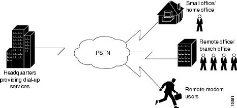
shows a headquarters network providing dial-up services to one small office/home office (SOHO), one remote office/branch office (ROBO), and remote modem users.
Figure 1-1 Business Scenario
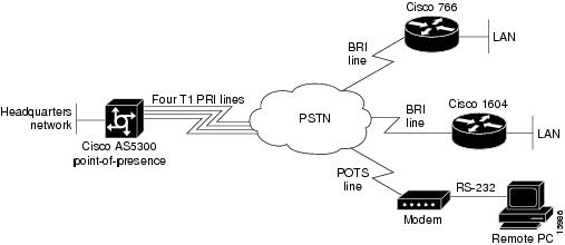
shows some of the physical elements present at layer 1 of the Open System Interconnection (OSI) reference model. The public switched telephone network (PSTN) provides the core interconnecting fabric between devices.
Figure 1-2 OSI Layer 1 Elements
In this scenario, a single Cisco AS5300 supports 96 concurrent modem and ISDN connections using four T1 PRI lines and 96 integrated modems. Modem connections are established via the Cisco IOS lines and corresponding asynchronous interfaces. Digital ISDN connections are established via the Cisco IOS channelized serial interfaces.
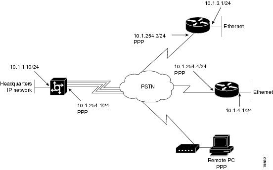
shows the layer 2 and layer 3 elements. The links going across the PSTN use the Point-to-Point Protocol (PPP). In this case study scenario PPP negotiates the link control protocol (LCP), CHAP or PAP authentication, and IP Control Protocol (IPCP) to bring up IP over PPP. IPCP is the network control protocol (NCP) used in this case study. IPCP is the mechanism that opens the links and negotiates the IP parameters.
Figure 1-3 OSI Layer 2 and Layer 3
Elements
summarizes the types of services provided by the headquarters POP to the remote nodes and sites. For more information, see .
Table 1-1 Scenarios and Site Characteristics Provided by Headquarters
Remote node modem
Modem
Asynchronous shell2 (async shell) Asynchronous PPP (async PPP)
Dial in only4. Remote devices are assigned an IP address from a central pool.
Remote node ISDN
ISDN routers using port address translation (PAT)3 , PC-based ISDN terminal adapters
Synchronous PPP (sync PPP)
Dial in only4 . PAT enabled. Connecting devices are assigned an IP address from a central pool.
Remote office LAN
Cisco 1604
Synchronous PPP
Dial in and dial out4. Distinct IP subnet. PAT not used.
Small office LAN
Cisco 766
Synchronous PPP
Dial in and dial out4. Distinct IP subnet. PAT not used.
1 This is the typical hardware required at the remote site.
2 Cisco IOS shell terminal services can be used for low-level troubleshooting on asynchronous connectivity. The shell is the service you use to access the command line interface. The shell provides you with a terminal screen.
3 PAT = Port address translation. Easy IP is an implementation of PAT. PAT vastly simplifies IP addressing design when supporting remote sites. This case study does not describe how to configure PAT. For more information, see the Dial Solutions Configuration Guide. PAT is mentioned in this table to show you how the technology is positioned in the remote access paradigm.
4 Unless otherwise stated, the terms "dial-in" and "dial-out" are from the perspective of the Cisco AS5300.
Design Architecture
The following sections provide the framework for this case study:
Service Definitions
In this case study, the Cisco AS5300 offers three basic services: async shell, async PPP, and sync PPP. See .
These services are based on real needs as requested by the remote sites. To access these services, remote devices connect to the Cisco AS5300 via the PSTN.
Table 1-2 Services Provided by Headquarters
Method UsedAsync shell
Provides access to Cisco IOS terminal services (no PPP) to do the following:2
•
•
•
•
Client modems, POTS3 , Cisco IOS integrated modems, lines, and asynchronous interfaces
Login
Async PPP
•
•
Client modems, POTS3, Cisco IOS integrated modems, lines, and asynchronous interfaces
PPP
(CHAP, PAP, or login)Sync PPP
•
•
End-to-end ISDN using B channels over a digital synchronous path, calls use interface serial channels (for example, S0:1, S0:2, and so forth)
PPP
(CHAP or PAP)
1 This is the equipment and interface path used to deliver calls into the Cisco AS5300. See .
2 Terminal services provided by the Cisco AS5300's integrated modems are terminated on TTY and VTY lines. The Cisco IOS shell is called the EXEC, which you can reach via a modem. The Cisco IOS shell is secured using "login" security. Authentication security associated with the EXEC is referred to as login. Sites offering terminal services can use menus to improve the user friendliness of the environment. For tips on how to create menus, see the Configuration Fundamentals Configuration Guide.
3 POTS = Plain old telephone service.
4 Terminal services via a shell are not available to synchronous link users (for example, ISDN routers and terminal adapters via a BRI channel). Only an asynchronous shell is available.
Layer 3 IP Design
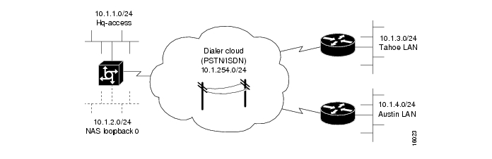
This case study uses PPP to transport IP packets across the PSTN and into the end-user devices (remote LAN or remote node). IPCP is the specific service enabled over the PPP links. To deliver this service, the case study uses address space from 10.1.0.0 /16. See the following figures and tables for the IP subnetting plan.
Figure 1-4
IP Subnetting Diagram
Table 1-3 IP Subnetting Plan
Hq-access
10.1.1.0 /24
Hq-access Ethernet
NAS loopback 01
10.1.2.0 /24
Loopback interface inside the Cisco AS5300
Dialer cloud
10.1.254.0 /24
Public switched telephone network
Tahoe LAN
10.1.3.0 /24
Tahoe Ethernet
Austin LAN
10.1.4.0 /24
Austin Ethernet
...2
...
...
...
...
...
1 NAS = network access server. The loopback subnet supports the remote node devices.
2 These dots mean that you can add additional subnets and remote LANs to this solution. This case study gives you a basic foundation from which you can scale to support larger dial implementations.
Using the subnetting plan and topologies shown in the previous tables and figures, a router naming and addressing plan is created in . Notice that the IP addresses are derived directly from the subnet plan.
Table 1-4 Router IP Addressing Plan
IP Address
IP Addresshq-sanjose
10.1.254.1 255.255.255.0
10.1.1.10 255.255.255.0
soho-tahoe
10.1.254.3 255.255.255.0
10.1.3.1 255.255.255.0
robo-austin
10.1.254.4 255.255.255.0
10.1.4.1 255.255.255.0
...2
...
...
...
...
...
1 Using the subnetting plan and topologies shown in the previous tables and figures, a router naming and addressing plan is created in are now assigned host names.
2 These dots mean that you can add additional subnets and remote LANs to this solution. This case study gives you a basic foundation from which you can scale to support larger dial implementations.
IP Subnet Rationale
This section describes each IP subnet and its design criteria. IP route summarization occurs at the gateway that connects the NAS to the IP backbone. IP range 10.1.0.0/16 is propagated to the backbone.
Hq-access Subnet
IP subnet 10.1.1.0/24 is assigned to the Ethernet connected to the Cisco AS5300. If additional access servers and POP management devices are needed, they are assigned to this IP subnet. Using one subnet for the entire headquarters dial access POP simplifies network design.
NAS Loopback 0 Subnet
IP subnet 10.1.2.0/24 is assigned to the loopback interface on the Cisco AS5300. This is the subnet used to host the remote node IP addresses. The access server has an IP pool range of 10.1.2.2 through 10.1.2.97.
Remote nodes dialing in request addresses from the Cisco AS5300's local IP address pool. This IP pool behaves like an address server handing out IP addresses to remote nodes during IPCP negotiation (a component of PPP).
Dialer Cloud Subnet
IP subnet 10.1.254.0/24 is assigned to the PSTN/ISDN. The static IP addresses are described in . See the column "WAN IP Address." The PSTN/ISDN becomes a "dialer cloud" from the Cisco IOS perspective. Dialer interfaces are used to connect to this dialer cloud. BRI and PRI interfaces are also dialer interfaces and use the same dial-on-demand routing (DDR) mechanisms to open and close circuit-switched connections.
A key design decision in this case study is to number the dialer cloud subnet. (That is, IP unnumbered is not used on these interfaces.) Numbering the dialer cloud ports to match the remote LAN supported by the same remote device is part of our design strategy to simplify administration. For example, remote subnet 10.1.3.0/24 is connected to the same remote site as dialer cloud node 10.1.254.3. IP node 10.1.254.4 supports IP subnet 10.1.4.0/24.
On the Cisco AS5300, all the individual serial channel interfaces are grouped together under one master dialer interface. As the individual remote sites connect, their configurations must coordinate with the configuration of the master dialer interface.
Tahoe and Austin LAN Subnets
IP subnet 10.1.3.0/24 is assigned to the Ethernet connected to the Cisco 766 (soho-tahoe). IP subnet 10.1.4.0/24 is assigned to the Cisco 1604 (robo-austin) Ethernet. Each site that supports a distinct IP subnet must be assigned its own distinct IP subnet address space. Routers with LANs behind them must have their own distinct IP subnets when not using PAT.
These remote LAN routers point to the central site as the default route. The hq-sanjose NAS is configured with static routes to the remote IP subnets.
Call Processing Components
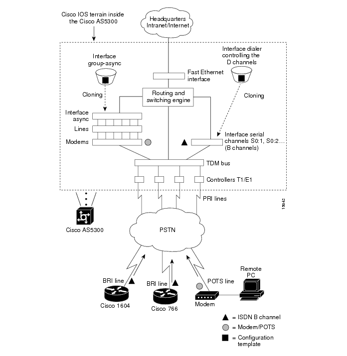
illustrates the connectivity path as calls come into the Cisco AS5300. The contents inside the dotted square box are the internal components of the Cisco AS5300. Both analog modem and digital calls enter the Cisco AS5300 via the E1/T1 controllers. Incoming modem calls are connected with the integrated modems and routed to the asynchronous interfaces. Incoming sync PPP calls are connected to the individual serial channels (for example, S0:1 and S0:2).
As shown in , one PPP/modem user consumes resources from one channel, one integrated modem, one line, and one asynchronous interface. An ISDN B-channel user connects directly via a channel of the T1 and a serial B-channel. The group-async and dialer interfaces are used to control the interfaces' behavior and configuration of async and serial channels.
Figure 1-5 Call Processing Components
Overview of Tasks
The network devices in this case study are manually configured using Cisco IOS software. The automatic Cisco IOS setup script is not used. This setup script usually runs when no startup configuration is found in NVRAM (for example, when powering up a new router).
Here is the action plan to build the network. For step-by-step configuration tasks, refer to the device-specific configuration chapters that follow.
Step 1
–
–
–
–
–
–
–
Step 2
–
–
–
Step 3
–
–
–
–
–
–
–
Step 4
–
–
–
–
–
–
–
–
Step 5
–
–
–
–
–
Related Documents and Web Tools
Refer to the following online resources for more information:
•
http://www.cisco.com/univercd/cc/td/doc/cisintwk/ics/index.htm
•
http://www.cisco.com/warp/public/793/access_dial/
•
http://www.cisco.com/univercd/cc/td/doc/product/software/ios113ed/113ed_cr/index.htm
•
http://www.cisco.com/univercd/cc/td/doc/cisintwk/ito_doc/55168.htm
•
http://te.cisco.com/cgi-bin/webcgi.exe?New,KB=TE
•
http://www.cisco.com/univercd/cc/td/doc/product/access/acs_serv/index.htm
Note