Feedback
Table Of Contents
Step 1—Configuring System Level Settings
Step 2—Configuring the LAN Profile
Step 3—Configuring the Site Profile hq-sanjose
Step 4—Testing Connections to the Cisco AS5300
Step 5—Confirming the Final Running Configuration
Cisco 766 Configuration
This chapter describes how to configure the Cisco 766 to dial out to the Cisco AS5300.
Site Profile Characteristics
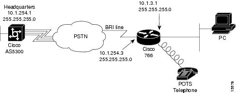
Figure 4-1 shows the network topology from the Cisco 766's perspective.
Figure 4-1
Network Topology
provides detailed information about each end of the connection. This is the network administrator's top-level design table.
Table 4-1 Site Characteristics
Username
Password
IP Address1
IP Addresssoho-tahoe
tahoe-pw
10.1.254.3 255.255.255.0
10.1.3.1 255.255.255.0
Directory numbers = 5558084
5558085Cisco 766
hq-sanjose
hq-sanjose-pw
10.1.254.1 255.255.255.0
10.1.1.10 255.255.255.0
4085551234
Cisco AS5300
1 The Cisco 766's default route is 10.1.254.1, which is the Cisco AS5300's dialer interface IP address. This is the next hop IP address.
Note
To enhance readability throughout this chapter, the most important output fields are highlighted with bold font. The commands you enter are also bold but are preceded by a router prompt.
Overview of Tasks
Perform the following steps:
•
•
•
•
•
Note
Step 1—Configuring System Level Settings
System level settings include system name, security, ISDN setup, and PPP setup.
Configure
To configure the system level settings, use the following commands in system mode:
1
> set system soho-tahoe
Enter the host name for this Cisco 766.
2
soho-tahoe> set switch ni1
Specify the ISDN switch type that your phone company uses.
3
soho-tahoe> set 1 directorynumber 5558084
soho-tahoe> set 2 directorynumber 5558085Enter the directory numbers for the BRI port's two B channels.
4
soho-tahoe> set 1 spid 53055580840101
soho-tahoe> set 2 spid 53055580850101Configure your SPIDs, which are required by many switches types. The SPID number is a derivative of the directory number.
5
soho-tahoe> set phone1 5558084
soho-tahoe> set phone2 5558085Enable calls to route to the phone 1 and phone 2 POTS jacks.
6
soho-tahoe> set voicepriority out conditional
soho-tahoe> set voicepriority in conditionalSet the incoming and outgoing voice priority mode. It determines whether the system will disconnect a B channel assigned to a data call to allow a voice call.
7
soho-tahoe> set ppp multilink on
Turn on multilink PPP.
8
soho-tahoe> set ppp authentication incoming chap
Authenticate incoming callers using CHAP.
9
soho-tahoe> set ppp secret host
Enter new password: tahoe-pw
Re-Type new password: tahoe-pwSpecify the CHAP password for authenticating PPP peers. You must enter it twice for verification1 .
10
soho-tahoe> set password system
Enter new password: admin-pw
Re-Type new password: admin-pwProtect your Cisco 766 terminal service shell with a password1. The system configuration mode can be accessed through the console port or a telnet session2 .
1 Make sure to use your own secret password. Do not use "tahoe-pw" or "admin-pw."
2 To modify what is protected by the password, use the set local access command.
Verify
To verify the configuration:
•
Note
soho-tahoe> show configurationSystem ParametersEnvironmentScreen Length 20Echo Mode ONCountryGroup 1Bridging ParametersLAN Forward Mode ANYWAN Forward Mode ONLYAddress Age Time OFFCall Startup ParametersMultidestination OFFLine ParametersSwitch Type NI-1Svc Profile ID 1 53055580840101Directory Number(s) 5558084Svc Profile ID 2 53055580850101Directory Number(s) 5558085Auto SPID and Switch Detection OFFConference access code 60Transfer access code 61Call Parameters Link 1 Link 2Retry Delay 30 30Button StandardProfile ParametersBridging ParametersBridging ONRouted Protocols NONELearn Mode ONPassthru OFFCall Startup ParametersLine ParametersLine Speed AUTONumbering Plan NORMALCall Parameters Link 1 Link 2Auto ON ONCalled NumberBackup NumberRingback NumberCLI Validate NumberCLICallback OFFCLIAuthentication OFF•
soho-tahoe> show securitySystem ParametersSecurityAccess Status ONSystem Password EXISTSRemote Configuration PROTECTEDLocal Configuration ONClickStart ONLogout Timeout 5Caller ID Security OFFCaller Id NumbersPPP SecurityPPP Authentication IN CHAPCHAP REFUSE NONEProfile ParametersPPP SecurityPPP Authentication OUT NONEPPP Authentication ACCEPT EITHERToken Authentication SupportTAS Client 0.0.0.0Use Local CHAP Secret ONClientUser Name soho-tahoePAP Password NONECHAP Secret NONEHostPAP Password NONECHAP Secret EXISTSCallbackRequest OFFReply OFF•
soho-tahoe> show statusStatus 01/01/1998 00:01:08Line StatusLine ActivatedTerminal Identifier Assigned SPID AcceptedTerminal Identifier Assigned SPID AcceptedPort Status InterfaceConnection LinkCh: 1 Waiting for CallCh: 2 Waiting for CallStep 2—Configuring the LAN Profile
The LAN profile contains the Cisco 766's Ethernet IP address and routing characteristics. Before you configure the LAN profile, you should understand how profiles work.
The Cisco 766's operating system uses a profile model. The LAN and remote site parameters are configured inside profiles. When using the command line interface for configuring the device, the current mode determines the effect and display output of each command. The current mode is indicated by the router prompt. To move between modes, use the cd command.
soho-tahoe>       <----------------------- This is system mode.
soho-tahoe> cd lan    <------------------- Change to the LAN profile.
soho-tahoe:LAN> cd hq-sanjose     <------- Change to the hq-sanjose profile.
soho-tahoe:hq-sanjose> cd    <------------ Go back to system mode.
soho-tahoe>
Note
In the following example, notice that the output of the show security command is different for each configuration mode.
soho-tahoe> show securitySystem ParametersSecurityAccess Status ONSystem Password EXISTSRemote Configuration PROTECTEDLocal Configuration ONClickStart ONLogout Timeout 5Caller ID Security OFFCaller Id NumbersPPP SecurityPPP Authentication IN CHAPCHAP REFUSE NONEProfile ParametersPPP SecurityPPP Authentication OUT NONEPPP Authentication ACCEPT EITHERToken Authentication SupportTAS Client 0.0.0.0Use Local CHAP Secret ONClientUser Name soho-tahoePAP Password NONECHAP Secret NONEHostPAP Password NONECHAP Secret EXISTSCallbackRequest OFFReply OFFsoho-tahoe> cd hq-sanjosesoho-tahoe:hq-sanjose> show securityProfile ParametersPPP SecurityPPP Authentication OUT NONE<*>PPP Authentication ACCEPT EITHERToken Authentication SupportTAS Mode OFFTAS Client 0.0.0.0Use Local CHAP Secret ONClientUser Name soho-tahoePAP Password NONECHAP Secret EXISTSHostPAP Password NONECHAP Secret EXISTSCallbackRequest OFFReply OFFConfigure
To configure the LAN profile parameters, use the following commands beginning in system configuration mode:
Verify
To verify the configuration:
•
soho-tahoe:LAN> show configurationProfile ParametersBridging ParametersBridging OFF<*>Routed Protocols IP <*>Learn Mode ONPassthru OFFCall Startup ParametersLine ParametersLine Speed AUTONumbering Plan NORMALCall Parameters Link 1 Link 2Auto ON ONCalled NumberBackup NumberRingback NumberCLI Validate NumberCLICallback OFFCLIAuthentication OFF•
soho-tahoe:LAN> show lan packetsPacket Statistics for LANFiltered: 120 Forwarded: 1 Received: 124Dropped: 0 Lost: 0 Corrupted: 0 Misordered: 0Ethernet Type: 0800 Count: 15Ethernet Type: 0806 Count: 7Step 3—Configuring the Site Profile hq-sanjose
The hq-sanjose profile provides the dialing characteristics for connecting to the Cisco AS5300 (hq-sanjose).
Configure
To configure the site profile, use the following commands beginning in LAN profile mode:
1
soho-tahoe:LAN> set user hq-sanjose
soho-tahoe> New user hq-sanjose being createdCreate the profile for the headquarters NAS.
This profile name must match the PPP name sent by the NAS during CHAP authentication1 .
2
soho-tahoe:hq-sanjose> set prof power=activate user=hq-sanjose
soho-tahoe:hq-sanjose> set activeEnsure that the profile is currently active and active at reboot.
3
soho-tahoe:hq-sanjose> set encap ppp
Enable PPP encapsulation.
4
soho-tahoe:hq-sanjose> set ip routing on
Turn on IP routing.
5
soho-tahoe:hq-sanjose> set ip framing none
Set IP framing for PPP encapsulation.
6
soho-tahoe:hq-sanjose> set ip address 10.1.254.3
Set the IP address to be used on the WAN port when using this profile. See .
7
soho-tahoe:hq-sanjose> set ip netmask 255.255.255.0
Set the IP netmask address for the dialer cloud.
8
soho-tahoe:hq-sanjose> set ip route destination 0.0.0.0 gateway 10.1.254.1
Create a static route for the next hop, which is the Cisco AS5300's WAN port. IP address 10.1.254.1 is used on the Cisco AS5300's dialer interface2 .
9
soho-tahoe:hq-sanjose> set bridging off
Turn off bridging.
10
soho-tahoe:hq-sanjose> set ip rip update off
Turn off IP RIP updates.
11
soho-tahoe:hq-sanjose> set number 14085551234
Enter the hq-sanjose telephone number.
12
soho-tahoe:hq-sanjose> set speed 56k
Start your connection testing with 56K, which is often a more dependable connect speed3 .
13
soho-tahoe:hq-sanjose> set ppp authentication outgoing none
When soho-tahoe dials out, it will not authenticate hq-sanjose.
14
soho-tahoe:hq-sanjose> set ppp authentication incoming chap
All incoming PPP callers are authenticated with CHAP.
15
soho-tahoe:hq-sanjose> set ppp secret client
soho-tahoe:hq-sanjose> Enter new Password: tahoe-pw
soho-tahoe:hq-sanjose> Re-Type new Password: tahoe-pwSpecify the secret password to use when soho-tahoe is logging into hq-sanjose4 .
1 On Cisco IOS devices the PPP name is defined by one of the following commands: hostname, sgbp group, ppp pap sent-username, or ppp chap hostname.
2 By definition IP address 10.1.254.1 is connected to the Cisco 766's BRI interface, because the dialer's subnet contains address 10.1.254.1.
3 You are less likely to run into a problem by using 56K. After the connection is up and operational, try to upgrade the speed to 64K. Call blocking is more common at 64K than 56K. During the experiment, check to see if you have any reliability issues. The set speed auto command tells the router to try 64K. However, only a 64K end-to-end data path will work. If you are blocked, try again at 56K.
4 This secret client password must match the password configured on hq-sanjose. For example, the password "tahoe-pw" is in the central site's username soho-tahoe password tahoe-pw command. See the section "Configuring Site Definitions" in the chapter "Cisco AS5300 Configuration."
Verify
To verify the configuration:
•
soho-tahoe:hq-sanjose> show securityProfile ParametersPPP SecurityPPP Authentication OUT NONE<*>PPP Authentication ACCEPT EITHERToken Authentication SupportTAS Mode OFFTAS Client 0.0.0.0Use Local CHAP Secret ONClientUser Name soho-tahoePAP Password NONECHAP Secret EXISTSHostPAP Password NONECHAP Secret EXISTSCallbackRequest OFFReply OFF•
soho-tahoe:hq-sanjose> show configurationProfile ParametersBridging ParametersBridging OFF<*>Routed Protocols IP <*>Learn Mode ONPassthru OFFCall Startup ParametersLine ParametersLine Speed AUTONumbering Plan NORMALCall Parameters Link 1 Link 2Auto ON ONCalled Number 14085551234<*> 14085551234<*>Backup NumberRingback NumberCLI Validate NumberCLICallback OFFCLIAuthentication OFFStep 4—Testing Connections to the Cisco AS5300
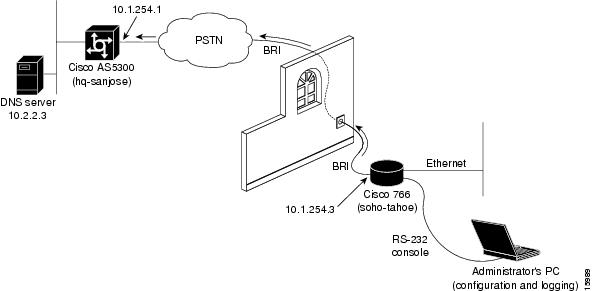
This section describes how to perform the test. shows the actual test lab environment used in this test case.
Figure 4-2
Test Lab Environment
Step 1
View this information in the hq-sanjose profile and at the system level. If the profile is shut down, you will not see the route at the system level.
soho-tahoe:hq-sanjose> show ip routeProfile Type Destination Bits Gateway Prop Cost Source Age------------------------------------------------------------------------------hq-sanjose NET 10.1.254.0 24 DIRECT ON 1 DIRECT 0soho-tahoe:hq-sanjose> cdsoho-tahoe> show ip routeProfile Type Destination Bits Gateway Prop Cost Source Age------------------------------------------------------------------------------LAN NET 10.1.3.0 24 DIRECT ON 1 DIRECT 0hq-sanjose NET 10.1.254.0 24 DIRECT ON 1 DIRECT 0Step 2
soho-tahoe> cd hq-sanjosesoho-tahoe:hq-sanjose> show connectionConnections 01/01/1998 00:04:47Start Date & Time # Name # Ethernet1 01/01/1998 00:00:00 # # 00 00 00 00 00 002 01/01/1998 00:02:36 # # 00 00 00 00 00 00Step 3
soho-tahoe:hq-sanjose> call ch201/01/1998 00:04:50 L05 0 14085551234 Outgoing Call Initiated01/01/1998 00:04:53 L08 2 14085551234 Call Connected01/01/1998 00:04:53 Connection 2 Add Link 1 Channel 2Step 4
soho-tahoe:hq-sanjose> ping 10.2.2.3Start sending: round trip time is 100 msec.Step 5
soho-tahoe:hq-sanjose> show connectionConnections 01/01/1998 00:05:42Start Date & Time # Name # Ethernet1 01/01/1998 00:00:00 # # 00 00 00 00 00 002 01/01/1998 00:02:36 # hq-sanjose #Link: 1 Channel: 2 Phone: 14085551234Step 6
soho-tahoe> show statusStatus 01/01/1998 00:47:50Line StatusLine ActivatedTerminal Identifier Assigned SPID AcceptedTerminal Identifier Assigned SPID AcceptedPort Status Interface Connection LinkCh: 1 56K Call In Progress 14085551234 DATA 2 1Ch: 2 Waiting for CallStep 7
Microsoft(R) Windows 95(C)Copyright Microsoft Corp 1981-1996.C:\WINDOWS> ping 10.2.2.3Pinging 10.1.3.2 with 32 bytes of data:Reply from 10.1.3.2: bytes=32 time=3ms TTL=236Reply from 10.1.3.2: bytes=32 time=2ms TTL=236Reply from 10.1.3.2: bytes=32 time=3ms TTL=236Reply from 10.1.3.2: bytes=32 time=2ms TTL=236Troubleshooting and Debugging Tips
•
•
•
Step 5—Confirming the Final Running Configuration
Here is the final configuration running on the Cisco 766. This configuration file can be used as a basic template for turning up additional remote sites. The bold entries are site specific. They should be customized for each site.
Timesaver
You can save time configuring a Cisco 766 by pasting a configuration file directly into a router. To do this, first return the router to its default state using the set default command. The router has no running configuration after this command is entered. Next, paste in the configuration file.
set system soho-tahoeset switch ni1set 1 spid 53055580840101set 2 spid 53055580850101set 1 directorynumber 5558084set 2 directorynumber 5558085set phone1 5558084set phone2 5558085set voice out conditionalset voice in conditionalset ppp multilink onset ppp authentication incoming chapset ppp secret hosttahoe-pwtahoe-pwset password systemadmin-pwadmin-pwcd lanset ip address 10.1.3.1set ip netmask 255.255.255.0set ip routing onset ip rip update offset bridging offcdset user hq-sanjoseset prof power=activate user=hq-sanjosecd hq-sanjoseset activeset encap pppset ip routing onset ip framing noneset ip address 10.1.254.3set ip netmask 255.255.0.0set ip pat offset ip rip update offset ip route destination 0.0.0.0 gateway 10.1.254.1set bridging offset number 14085551234set speed 56set ppp authentication outgoing noneset ppp authentication incoming chapset ppp secret clienttahoe-pwtahoe-pwcdrebootAfter you verify that the configuration works, initiate an upload at the end of the session and save it. An upload displays the setting of every configuration parameter on the Cisco 766.
soho-tahoe> uplCDSET SCREENLENGTH 20SET COUNTRYGROUP 1SET LAN MODE ANYSET WAN MODE ONLYSET AGE OFFSET MULTIDESTINATION OFFSET SWITCH NI-1SET 1 SPID 53055580840101SET 1 DIRECTORYNUMBER 5558084SET PHONE1 = 5558084SET 2 SPID 53055580850101SET 2 DIRECTORYNUMBER 5558085SET PHONE2 = 5558085SET AUTODETECTION OFFSET CONFERENCE 60SET TRANSFER 61SET 1 DELAY 30SET 2 DELAY 30SET BRIDGING ONSET LEARN ONSET PASSTHRU OFFSET SPEED AUTOSET PLAN NORMALSET 1 AUTO ONSET 2 AUTO ONSET 1 NUMBERSET 2 NUMBERSET 1 BACKUPNUMBERSET 2 BACKUPNUMBERSET 1 RINGBACKSET 2 RINGBACKSET 1 CLIVALIDATENUMBERSET 2 CLIVALIDATENUMBERSET CLICALLBACK OFFSET CLIAUTHENTICATION OFFSET SYSTEMNAME SOHO-TAHOELOG CALLS TIME VERBOSESET UNICASTFILTER OFFDEMAND 1 THRESHOLD 0DEMAND 2 THRESHOLD 48DEMAND 1 DURATION 1DEMAND 2 DURATION 1DEMAND 1 SOURCE LANDEMAND 2 SOURCE BOTHTIMEOUT 1 THRESHOLD 0TIMEOUT 2 THRESHOLD 48TIMEOUT 1 DURATION 0TIMEOUT 2 DURATION 0TIMEOUT 1 SOURCE LANTIMEOUT 2 SOURCE BOTHSET PASSWORD SYSTEM ENCRYPTED 0500120632484048SET REMOTEACCESS PROTECTEDSET LOCALACCESS ONSET CLICKSTART ONSET LOGOUT 5SET CALLERID OFFSET PPP AUTHENTICATION IN CHAPSET PPP CHAPREFUSE NONESET PPP AUTHENTICATION OUT NONESET PPP AUTHENTICATION ACCEPT EITHERSET PPP TAS CLIENT 0.0.0.0SET PPP TAS CHAPSECRET LOCAL ONSET PPP SECRET HOST ENCRYPTED 10471a1d0b43191f4d45SET PPP CALLBACK REQUEST OFFSET PPP CALLBACK REPLY OFFSET PPP NEGOTIATION INTEGRITY 10SET PPP NEGOTIATION COUNT 10SET PPP NEGOTIATION RETRY 3000SET PPP TERMREQ COUNT 2SET PPP MULTILINK ONSET COMPRESSION STACSET PPP BACP ONSET PPP ADDRESS NEGOTIATION LOCAL OFFSET PPP IP NETMASK LOCAL OFFSET IP PAT UDPTIMEOUT 5SET IP PAT TCPTIMEOUT 30SET IP RIP TIME 30SET CALLDURATION 0SET SNMP CONTACT ""SET SNMP LOCATION ""SET SNMP TRAP COLDSTART OFFSET SNMP TRAP WARMSTART OFFSET SNMP TRAP LINKDOWN OFFSET SNMP TRAP LINKUP OFFSET SNMP TRAP AUTHENTICATIONFAIL OFFSET DHCP OFFSET DHCP DOMAINSET DHCP NETBIOS_SCOPESET VOICEPRIORITY INCOMING INTERFACE PHONE1 CONDITIONALSET VOICEPRIORITY OUTGOING INTERFACE PHONE1 CONDITIONALSET CALLWAITING INTERFACE PHONE1 ONSET VOICEPRIORITY INCOMING INTERFACE PHONE2 CONDITIONALSET VOICEPRIORITY OUTGOING INTERFACE PHONE2 CONDITIONALSET CALLWAITING INTERFACE PHONE2 ONSET CALLTIME VOICE INCOMING OFFSET CALLTIME VOICE OUTGOING OFFSET CALLTIME DATA INCOMING OFFSET CALLTIME DATA OUTGOING OFFSET USER LANSET BRIDGING OFFSET IP ROUTING ONSET IP ADDRESS 10.1.3.1SET IP NETMASK 255.255.255.0SET IP FRAMING ETHERNET_IISET IP PROPAGATE ONSET IP COST 1SET IP RIP RECEIVE V1SET IP RIP UPDATE OFFSET IP RIP VERSION 1SET USER InternalSET IP FRAMING ETHERNET_IISET USER StandardSET PROFILE ID 000000000000SET PROFILE POWERUP ACTIVATESET PROFILE DISCONNECT KEEPSET IP ROUTING ONSET IP ADDRESS 0.0.0.0SET IP NETMASK 0.0.0.0SET IP FRAMING NONESET IP RIP RECEIVE V1SET IP RIP UPDATE OFFSET IP RIP VERSION 1SET USER HQ-SANJOSESET PROFILE ID 000000000000SET PROFILE POWERUP ACTIVATESET PROFILE DISCONNECT KEEPSET BRIDGING OFFSET SPEED 56KSET 1 NUMBER 14085551234SET 2 NUMBER 14085551234SET PPP AUTHENTICATION OUT NONESET PPP SECRET CLIENT ENCRYPTED 020f175f055204350d0fSET IP ROUTING ONSET IP ADDRESS 10.1.254.3SET IP NETMASK 255.255.0.0SET IP FRAMING NONESET IP PROPAGATE ONSET IP COST 1SET IP RIP RECEIVE V1SET IP RIP UPDATE OFFSET IP RIP VERSION 1SET IP PAT OFFSET IP ROUTE DEST 0.0.0.0/0 GATEWAY 10.1.254.1 PROPAGATE OFF COST 1CDSET BUTTON StandardLOGOUT