Prerequisites for Layer 2 Local Switching
You must enable Cisco Express Forwarding for the Cisco ASR 1000 Series Aggregation Services Router.
The documentation set for this product strives to use bias-free language. For the purposes of this documentation set, bias-free is defined as language that does not imply discrimination based on age, disability, gender, racial identity, ethnic identity, sexual orientation, socioeconomic status, and intersectionality. Exceptions may be present in the documentation due to language that is hardcoded in the user interfaces of the product software, language used based on RFP documentation, or language that is used by a referenced third-party product. Learn more about how Cisco is using Inclusive Language.
The Layer 2 Local Switching feature allows you to switch Layer 2 data in two ways:
Between two interfaces on the same router
Between two circuits on the same interface port, which is called same-port switching
The following interface-to-interface switching combinations are supported by this feature:
ATM to ATM
ATM to Ethernet
Ethernet/Ethernet VLAN to Ethernet/Ethernet VLAN
Frame Relay to Frame Relay
The following same-port switching features are supported:
ATM Permanent Virtual Circuit (PVC) and Permanent Virtual Path (PVP)
Ethernet VLAN
Frame Relay
You must enable Cisco Express Forwarding for the Cisco ASR 1000 Series Aggregation Services Router.
For Ethernet/Ethernet VLAN circuits, the Cisco ASR 1000 Series Aggregation Services Router must have Ethernet Adapters.
For Frame Relay local switching, you must globally issue the frame-relay switching command.
Local switching allows you to switch Layer 2 data between two interfaces of the same type (for example, Ethernet to Ethernet or Frame Relay to Frame Relay) or between interfaces of different types (for example, Ethernet VLAN to Ethernet VLAN or Ethernet to Ethernet VLAN) on the same router. The interfaces can be on the same line card or on two different cards. During these kinds of switching, the Layer 2 address is used, not the Layer 3 address.
Additionally, same-port local switching allows you to switch Layer 2 data between two circuits on the same interface.
Nonstop forwarding (NSF) and stateful switchover (SSO) improve the availability of the network by providing redundant Route Processors and checkpointing of data to ensure minimal packet loss when the primary Route Processor goes down. NSF/SSO support is available for the following locally switched attachment circuits:
Ethernet/Ethernet VLAN to Ethernet/Ethernet VLAN
Frame Relay to Frame Relay
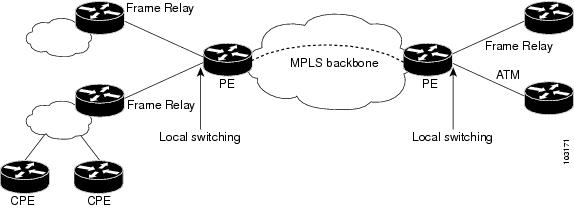
Incumbent local exchange carriers (ILECs) that use an interexchange carrier (IXC) to carry traffic between two local exchange carriers can use the Layer 2 Local Switching feature. Telecom regulations require the ILECs to pay the IXCs to carry that traffic. At times, the ILECs cannot terminate customer connections that are in different local access and transport areas (LATAs). In other cases, customer connections terminate in the same LATA, which may also be on the same router.
For example, company A has more than 50 LATAs across the country and uses three routers for each LATA. Company A uses companies B and C to carry traffic between local exchange carriers. Local switching of Layer 2 frames on the same router might be required.
Similarly, if a router is using, for example, a channelized interface, it might need to switch incoming and outgoing traffic across two logical interfaces that reside on a single physical port. The same-port local switching feature addresses that implementation.
The figure below shows a network that uses local switching for both Frame Relay to Frame Relay and ATM to Frame Relay local switching.
Perform this task to configure Ethernet VLAN same-port switching.
| Command or Action | Purpose | |
|---|---|---|
|
Step 1 |
enable Example: |
Enables privileged EXEC mode.
|
|
Step 2 |
configure terminal Example: |
Enters global configuration mode. |
|
Step 3 |
interface fastethernet slot / port . subinterface-number Example: |
Specifies the first Fast Ethernet line card, subslot (if available), port, and subinterface, and enters subinterface configuration mode. |
|
Step 4 |
encapsulation dot1q vlan-id Example: |
Enables the subinterface to accept 802.1Q VLAN packets and specifies the first VLAN. |
|
Step 5 |
exit Example: |
Exits subinterface configuration mode and returns to global configuration mode. |
|
Step 6 |
interface fastethernet slot / port . subinterface-number Example: |
Specifies the second Fast Ethernet line card, subslot (if available), port, and subinterface, and enters subinterface configuration mode. |
|
Step 7 |
encapsulation dot1q vlan-id Example: |
Enables the subinterface to accept 802.1Q VLAN packets and specifies the second VLAN. |
|
Step 8 |
exit Example: |
Exits subinterface configuration mode and returns to global configuration mode. |
|
Step 9 |
connect connection-name type number type number Example: |
Creates a local connection between the two subinterfaces (and hence their previously specified VLANs) on the same Fast Ethernet port. |
Perform this task to configure local switching for Ethernet (port mode) to Ethernet VLAN.
| Command or Action | Purpose | |
|---|---|---|
|
Step 1 |
enable Example: |
Enables privileged EXEC mode.
|
|
Step 2 |
configure terminal Example: |
Enters global configuration mode. |
|
Step 3 |
interface fastethernet slot / subslot / port Example: |
Specifies a Fast Ethernet line card, subslot (if available), and port, and enters interface configuration mode.
|
|
Step 4 |
interface fastethernet slot / port / subinterface-number Example: |
Specifies a Fast Ethernet line card, subslot (if available), port, and subinterface, and enters subinterface configuration mode.
|
|
Step 5 |
encapsulation dot1q vlan-id Example: |
Enables the interface to accept 802.1Q VLAN packets. |
|
Step 6 |
exit Example: |
Exits subinterface configuration mode and returns to global configuration mode. |
|
Step 7 |
connect connection-name type number type number Example: |
Creates a local connection between the two interfaces. |
You can configure local switching for both ATM AAL5 and ATM AAL0 encapsulation types.
Creating the ATM PVC is not required. If you do not create a PVC, one is created for you. For ATM-to-ATM local switching, the autoprovisioned PVC is given the default encapsulation type AAL0 cell relay.
| Command or Action | Purpose | |
|---|---|---|
|
Step 1 |
enable Example: |
Enables privileged EXEC mode.
|
|
Step 2 |
configure terminal Example: |
Enters global configuration mode. |
|
Step 3 |
interface atm slot / port Example: |
Specifies an ATM line card, subslot (if available), and port, and enters interface configuration mode. |
|
Step 4 |
pvc vpi / vci l2transport Example: |
Assigns a VPI and VCI and enters ATM PVC l2transport configuration mode.
|
|
Step 5 |
encapsulation layer-type Example: |
Specifies the encapsulation type for the ATM PVC. Both AAL0 and AAL5 are supported.
|
|
Step 6 |
exit Example: |
Exits PVC l2transport configuration mode and returns to interface configuration mode. |
|
Step 7 |
exit Example: |
Exits interface configuration mode and returns to global configuration mode. |
|
Step 8 |
connect connection-name interface pvc interface pvc Example: |
Creates a local connection between the two specified permanent virtual circuits. |
Perform this task to configure ATM-to-ATM PVP local switching.
Starting with Cisco IOS Release 12.0(30)S, you can configure same-port switching, as detailed in the Configuring ATM PVP Same-Port Switching.
| Command or Action | Purpose | |
|---|---|---|
|
Step 1 |
enable Example: |
Enables privileged EXEC mode.
|
|
Step 2 |
configure terminal Example: |
Enters global configuration mode. |
|
Step 3 |
interface atm slot/port Example: |
Specifies an ATM line card, subslot (if available), and port and enters interface configuration mode. |
|
Step 4 |
atm pvp vpi l2transport Example: |
Identifies the virtual path and enters PVP l2transport configuration mode. The l2transport keyword indicates that the PVP is a switched PVP instead of a terminated PVP.
|
|
Step 5 |
exit Example: |
Exits PVP l2transport configuration mode and returns to interface configuration mode. |
|
Step 6 |
exit Example: |
Exits interface configuration mode and returns to global configuration mode. |
|
Step 7 |
connect connection-name interface pvp interface pvp Example: |
Creates a local connection between the two specified permanent virtual paths. |
Perform this task to configure ATM PVP switching on an ATM interface.
| Command or Action | Purpose | |
|---|---|---|
|
Step 1 |
enable Example: |
Enables privileged EXEC mode.
|
|
Step 2 |
configure terminal Example: |
Enters global configuration mode. |
|
Step 3 |
interface atm slot/subslot/port Example: |
Specifies an ATM line card, subslot (if available), and port and enters interface configuration mode. |
|
Step 4 |
atm pvp vpi l2transport Example: |
Specifies one VPI and enters PVP l2transport configuration mode. Repeat this step for the other ATM permanent virtual path on this same port.
|
|
Step 5 |
exit Example: |
Exits PVP l2transport configuration mode and returns to interface configuration mode. |
|
Step 6 |
exit Example: |
Exits interface configuration mode and returns to global configuration mode. |
|
Step 7 |
connect connection-name interface pvp interface pvp Example: |
Creates the local connection between the two specified permanent virtual paths. |
For information about Frame Relay-to-Frame Relay local switching, see the Distributed Frame Relay Switching feature module.
| Command or Action | Purpose | |
|---|---|---|
|
Step 1 |
enable Example: |
Enables privileged EXEC mode.
|
|
Step 2 |
configure terminal Example: |
Enters global configuration mode. |
|
Step 3 |
ip cef distributed Example: |
Enables Cisco Express Forwarding operation. |
|
Step 4 |
frame-relay switching Example: |
Enables PVC switching on a Frame Relay DCE device or a Network-to-Network Interface (NNI). |
|
Step 5 |
interface type number Example: |
Specifies a Frame Relay interface and enters interface configuration mode. |
|
Step 6 |
encapsulation frame-relay [cisco | ietf ] Example: |
Enables Frame Relay encapsulation.
|
|
Step 7 |
frame-relay interface-dlci dlci switched Example: |
(Optional) Creates a switched PVC and enters Frame Relay DLCI configuration mode.
|
|
Step 8 |
exit Example: |
Exits Frame Relay DLCI configuration mode and returns to interface configuration mode. |
|
Step 9 |
exit Example: |
Exits interface configuration mode and returns to global configuration mode. |
|
Step 10 |
connect connection-name interface dlci interface dlci Example: |
Defines a connection between Frame Relay PVCs. |
To verify configuration of the Layer 2 local switching feature, use the show connection command on the provider edge (PE) router.
|
show connection [all | element | id id | name name | port port ] The show connection command displays the local connection between a Gigabit Ethernet interface and another local Gigabit Ethernet interface: Example: |
Layer 2 local switching provides NSF/SSO support for Local Switching of the following attachment circuits on the same router:
Ethernet/Ethernet VLAN to Ethernet/Ethernet VLAN
For information about configuring NSF/SSO on the Route Processors, see the " Stateful Switchover " module in the Cisco IOS XE High Availability Configuration Guide . Perform this task to verify that the NSF/SSO: Layer 2 Local Switching feature is working correctly.
|
Step 1 |
ping Issue the ping command or initiate traffic between the two CE routers. |
|
Step 2 |
redundancy force-switchover Force the switchover from the active RP to the standby RP by using the redundancy force-switchover command. This manual procedure allows for a "graceful" or controlled shutdown of the active RP and switchover to the standby RP. This graceful shutdown allows critical cleanup to occur. |
|
Step 3 |
show connection all Issue the show connection all command to ensure that the Layer 2 local switching connection on the dual RP is operating: Example: |
|
Step 4 |
ping Issue the ping command from the CE router to verify that the contiguous packet outage was minimal during the switchover. |
You can troubleshoot Layer 2 local switching using the following commands on the PE router:
debug conn
show connection
The following example shows same-port switching between two VLANs on one Ethernet interface:
interface fastethernet 0/0.1
 encapsulation dot1q 1
interface fastethernet 0/0.2
 encapsulation dot1q 2
connect conn FastEthernet 0/0.1 FastEthernet 0/0.2The following configuration uses the network topology shown in the figure below.
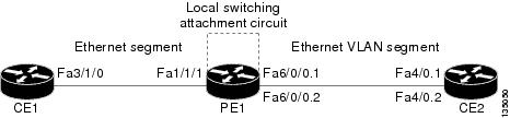
The following example shows the configuration of the CE interfaces to connect to the PE1 router:
|
CE1 |
CE2 |
|---|---|
|
|
The following example shows the configuration of the PE1 router with NSF/SSO and the PE interfaces to the CE routers:
PE1
redundancy
no keepalive-enable
mode sso
!
!
ip routing
ip cef distributed
!
interface fa1/1/1
description - connection to CE1 fa3/1/0
no shutdown
no ip address
!
!
interface fa6/0/0
no shutdown
no ip address
!
interface fa6/0/0.1
description - connection to CE2 fa4/0.1
encapsulation dot1Q 10
no ip address
!
interface fa6/0/0.2
description - connection to CE2 fa4/0.2
encapsulation dot1Q 20
no ip addressThe following example shows local switching on ATM interfaces configured for AAL5:
interface atm1/0/0
 pvc 0/100 l2transport
 encapsulation aal5
interface atm2/0/0
 pvc 0/100 l2transport
 encapsulation aal5
connect aal5-conn atm1/0/0 0/100 atm2/0/0 0/100The following example shows same-port switching between two PVCs on one ATM interface:
interface atm1/0/0
 pvc 0/100 l2transport
 encapsulation aal5
 pvc 0/200 l2transport
 encapsulation aal5
connect conn atm1/0/0 0/100 atm1/0/0 0/200The following example shows same-port switching between two PVPs on one ATM interface:
interface atm1/0/0
 atm pvp 100 l2transport
 atm pvp 200 l2transport
connect conn atm1/0/0 100 atm1/0/0 200The following example shows serial interfaces configured for Frame Relay. The connect command allows local switching between these two interfaces.
frame-relay switching
ip cef distributed
interface serial3/0/0
 encapsulation frame-relay
 frame-relay interface-dlci 100 switched
 frame-relay intf-type dce
interface serial3/1/0
 encapsulation frame-relay ietf
 frame-relay interface-dlci 200 switched
 frame-relay intf-type dce
connect fr-con serial3/0/0 100 serial3/1/0 200 |
Related Topic |
Document Title |
|---|---|
|
Cisco IOS commands |
|
|
WAN Commands |
Cisco IOS Wide-Area Networking Command Reference |
|
Stateful switchover configuration information |
"Stateful Switchover " module in the Cisco IOS XE High Availability Configuration Guide |
|
Standard |
Title |
|---|---|
|
draft-ietf-l2tpext-l2tp-base-03.txt |
Layer Two Tunneling Protocol (Version 3) 'L2TPv3' |
|
draft-martini-l2circuit-trans-mpls-09.txt |
Transport of Layer 2 Frames Over MPLS |
|
draft-martini-l2circuit-encap-mpls-04.txt |
Encapsulation Methods for Transport of Layer 2 Frames Over IP and MPLS Networks |
|
draft-ietf-ppvpn-l2vpn-00.txt |
An Architecture for L2VPNs |
|
MIB |
MIBs Link |
|---|---|
|
None |
To locate and download MIBs for selected platforms, Cisco IOS XE software releases, and feature sets, use Cisco MIB Locator found at the following URL: |
|
RFC |
Title |
|---|---|
|
None |
-- |
|
Description |
Link |
|---|---|
|
The Cisco Support and Documentation website provides online resources to download documentation, software, and tools. Use these resources to install and configure the software and to troubleshoot and resolve technical issues with Cisco products and technologies. Access to most tools on the Cisco Support and Documentation website requires a Cisco.com user ID and password. |
The following table provides release information about the feature or features described in this module. This table lists only the software release that introduced support for a given feature in a given software release train. Unless noted otherwise, subsequent releases of that software release train also support that feature.
Use Cisco Feature Navigator to find information about platform support and Cisco software image support. To access Cisco Feature Navigator, go to www.cisco.com/go/cfn. An account on Cisco.com is not required.|
Feature Name |
Releases |
Feature Information |
|---|---|---|
|
Layer 2 Local Switching |
Cisco IOS XE Release 2.5 |
The Layer 2 Local Switching feature allows you to switch Layer 2 data between two interfaces on the same router, and in some cases to switch Layer 2 data between two circuits on the same interface port.
The following commands were introduced or modified: connect (L2VPN local switching), show connection . |
|
Layer 2 Local Switching - ATM to ATM |
Cisco IOS XE Release 3.3S |
In Cisco IOS XE Release 3.3S, this feature was introduced on the Cisco ASR 1000 Series Aggregation Services Routers. The following commands were introduced or modified: connect (L2VPN local switching), show connection . |
|
Layer 2 Local Switching - Frame Relay to Frame Relay |
Cisco IOS XE Release 3.9S |
In Cisco IOS XE Release 3.9S, this feature was introduced on the Cisco ISR 4400 Series Routers. |
 Feedback