- Overview of Cisco Unified Communications Manager and Interoperability
- Configuring MGCP Gateway Support
- Configuring Conferencing and Transcoding for Voice Gateway Routers
- Configuring MGCP PRI Backhaul and T1 CAS Support
- Configuring MGCP-Controlled Backhaul of BRI Signaling
- Configuring Tone Download to MGCP Gateways
- Configuring MCID for Cisco IOS Voice Gateways
- Configuring RSVP Agent
- VoIP for IPv6
Contents
- Configuring Conferencing and Transcoding for Voice Gateway Routers
- Finding Feature Information
- Prerequisites for Conferencing and Transcoding for Voice Gateway Routers
- Restrictions for Conferencing and Transcoding for Voice Gateway Routers
- Information About Conferencing and Transcoding for Voice Gateway Routers
- DSP Farms
- DSP Farm Profiles
- Conferencing
- Transcoding
- Media Termination Point
- Conferencing and Transcoding Features on the NM-HDV2 and NM-HD-1V 2V 2VE
- Conferencing and Transcoding Features on the NM-HDV
- Conferencing and Transcoding Features on the Cisco 1751 and Cisco 1760
- Allocation of DSP Resources
- Allocation of DSP Resources Within the Voice Network Module
- Allocation of DSP Resources Within the DSP Farm
- Conferencing and Transcoding Session Capacities
- NM-HDV System Capacities
- How to Configure Conferencing and Transcoding for Voice Gateway Routers
- Determining DSP Resource Requirements
- Enabling SCCP on the Cisco Unified Communications Manager Interface
- Configuring Enhanced Conferencing and Transcoding
- Configuring a DSP Farm Profile
- Associating a DSP Farm Profile to a Cisco Unified Communications Manager Group
- Modifying Default Settings for SCCP Connection to Cisco Unified Communications Manager
- Verifying DSP Farm Configuration
- Tips for Troubleshooting Conferencing and Transcoding on Voice Gateway Routers
- Troubleshooting DSP-Farm Services
- Configuring Conferencing and Transcoding (NM-HDV)
- Configuring the DSP Farm on the NM-HDV
- Tuning DSP-Farm Performance on the NM-HDV
- What to Do Next
- Configuring Conferencing and Transcoding (PVDM-256K)
- What to Do Next
- Configuring Out-of-Band to In-Band DTMF Relay
- Prerequisites
- Restrictions
- Out-of-Band to In-Band DTMF Relay for Cisco IOS Voice Gateways
- Configuration Examples for Conferencing and Transcoding
- DSP-Farm Services on the NM-HDV2 or PVDM2 Example
- DSP-Farm Services on the NM-HDV Example
- Tuning DSP-Farm Services on the NM-HDV Example
- DSP-Farm Services on the Cisco 1760 Example
- Dut-Band to In-Band DTMF Relay on Cisco 2801 Example
- Out-Band to In-Band DTMF Relay on Cisco 3725 Example
- SIP Gateway Example
- Universal Transcoding with an Inbox on a Universal Gateway Example
- G.711 to Any Transcoding with an Inbox on a Universal Gateway Example
- Universal and G.711 to Any Transcoding with an Inbox on a Universal Gateway Example
- Universal and G.711 to Any Transcoding with an Inbox on an ISR Example
- Where to Go Next
- Additional References
Configuring Conferencing and Transcoding for Voice Gateway Routers
This chapter describes the steps for enabling conferencing and transcoding support on Cisco IOS voice gateways in a Cisco Unified Communications Manager network. This feature provides enhanced multiservice support by enabling audioconference and transcode functions in voice gateway routers. Locating conference resources in the branch reduces WAN utilization and using transcoding services reduces bandwidth needs resulting in tangible cost savings.
Digital signal processor (DSP) farms provide conferencing and transcoding services using DSP resources on high-density digital voice/fax network modules.
Feature History for G.722-64 and iLBC Codec Support on Cisco Unified Communications Manager Express
|
Release |
Modification |
|---|---|
|
12.4(15)XZ |
This feature was introduced. |
|
15.0(1)M |
This feature was integrated into Cisco IOS Release 15.0(1)M. |
Feature History for G.722-64 and iLBC Codec Support on Cisco UBEs, DSP Farms, and Voice Gateways
|
Release |
Modification |
|---|---|
|
12.4(15)XY |
This feature was introduced. |
|
15.0(1)M |
This feature was integrated into Cisco IOS Release 15.0(1)M. |
Feature History for Universal Voice Transcoding Support for Cisco Unified Border Elements
|
Release |
Modification |
|---|---|
|
12.4(11)XY |
This feature was introduced. |
|
15.0(1)M |
This feature was integrated into Cisco IOS Release 15.0(1)M. |
Feature History for Out-of-Band to In-Band DTMF Relay for Voice Gateway Routers
|
Release |
Modification |
|---|---|
|
12.3(8)XY |
This feature was introduced. |
|
12.3(11)T |
This feature was integrated into Cisco IOS Release 12.3(11)T. |
|
12.3(14)T |
Support was added for the PVDM2 on the Cisco 2800 series and Cisco 3800 series voice gateway routers. |
Feature History for Enhanced Conferencing and Transcoding for Voice Gateway Routers
|
Release |
Modification |
|---|---|
|
12.3(8)T |
This feature was introduced for the NM-HDV2, NM-HD-1V, NM-HD-2V, and NM-HD-2VE. |
|
12.3(11)T |
Support was added for the PVDM2 on the Cisco 2800 series and Cisco 3800 series voice gateway routers. |
Feature History for Conferencing and Transcoding for Voice Gateway Routers
|
Release |
Modification |
|---|---|
|
12.1(5)YH |
This feature was introduced for the NM-HDV-FARM on the Cisco VG200. |
|
12.2(13)T |
This feature was integrated into Cisco IOS Release 12.2(13)T and support was added for the NM-HDV on the Cisco 2600 series, Cisco 3600 series, Cisco 3700 series, and Cisco VG200. |
|
12.3(2)XE |
Support was added for the PVDM-256K on the Cisco 1751, Cisco 1751-V, and Cisco 1760. |
|
12.3(8)T |
Support for the PVDM-256K on the Cisco 1751, Cisco 1751-V, and Cisco 1760 was integrated into Cisco IOS Release 12.3(8)T. |
Finding Support Information for Platforms and Cisco IOS Software Images
Use Cisco Feature Navigator to find information about platform support and Cisco IOS software image support. Access Cisco Feature Navigator at http://www.cisco.com/go/fn . You must have an account on Cisco.com. If you do not have an account or have forgotten your username or password, click Cancel at the login dialog box and follow the instructions that appear.
For more information about this and related Cisco IOS voice features, see the following:
- "Overview of Cisco Unified Communications Manager and Cisco IOS Interoperability" on page 13 .
- Entire Cisco IOS Voice Configuration Library--including library preface and glossary, other feature documents, and troubleshooting documentation--at http://www.cisco.com/univercd/cc/td/doc/product/software/ios123/123cgcr/voice_c/vcl.htm .
- Finding Feature Information
- Prerequisites for Conferencing and Transcoding for Voice Gateway Routers
- Restrictions for Conferencing and Transcoding for Voice Gateway Routers
- Information About Conferencing and Transcoding for Voice Gateway Routers
- How to Configure Conferencing and Transcoding for Voice Gateway Routers
- Configuration Examples for Conferencing and Transcoding
- Where to Go Next
- Additional References
Finding Feature Information
Your software release may not support all the features documented in this module. For the latest caveats and feature information, see Bug Search Tool and the release notes for your platform and software release. To find information about the features documented in this module, and to see a list of the releases in which each feature is supported, see the feature information table at the end of this module.
Use Cisco Feature Navigator to find information about platform support and Cisco software image support. To access Cisco Feature Navigator, go to www.cisco.com/go/cfn. An account on Cisco.com is not required.
Prerequisites for Conferencing and Transcoding for Voice Gateway Routers
DSP Resources
The router must be equipped with one or more of the following network modules or voice DSP modules to provide DSP resources for conferencing, transcoding, and hardware MTP services:
|
NM-HDV1 |
|
NM-HDV-FARMPrerequisites for Conferencing and Transcoding for Voice Gateway Routers |
|
PVDM-256KPrerequisites for Conferencing and Transcoding for Voice Gateway Routers |
Cisco Unified Communications Manager and Cisco IOS Release
Minimum software requirements for type of network or voice module:
|
Module |
Cisco Unified Communications Manager version |
Cisco IOS Release |
|---|---|---|
|
NM-HDV2, NM-HD-1V/2V/2VE |
Cisco Unified Communications Manager 3.3(4) (formerly known as Cisco CallManager 3.3(4)) or later for conferencing and transcoding, Cisco Unified Communications Manager 4.0(1) (formerly known as Cisco CallManager 4.0(1)) or later for MTP |
Cisco IOS Release 12.3(8)T or later |
|
PVDM2 (Cisco 2800 series) |
Cisco Unified Communications Manager 3.3(5) (formerly known as Cisco CallManager 3.3(5)) or later for conferencing and transcoding, Cisco Unified Communications Manager 4.0(2a) (formerly known as Cisco CallManager 4.0(2a)) or later for MTP |
Cisco IOS Release 12.3(8)T4 or later |
|
PVDM2 (Cisco 3800 series) |
Cisco Unified Communications Manager 3.3(5) (formerly known as Cisco CallManager 3.3(5)) or later for conferencing and transcoding, Cisco Unified Communications Manager 4.0(2a) (formerly known as Cisco CallManager 4.0(2a)) or later for MTP |
Cisco IOS Release 12.3(11)T or later |
|
NM-HDV |
Cisco Unified Communications Manager 3.2(2c) (formerly known as Cisco CallManager 3.2(2c)) or later |
Cisco IOS Release 12.2(13)T or later |
- Conference bridge, transcoder, and MTP services must be configured in Cisco Unified Communications Manager. See the following chapters in the Cisco Unified Communications Manager Administration Guide :
Release 4.0(1):
Release 3.3(4):
Codecs
End-user devices must be equipped with one of the following codecs:
|
Codec |
Packetization Periods for Transcoding (ms) |
|---|---|
|
G.711 a-law, G.711 u-law, G.722-64 |
10, 20, or 30 |
|
G.729, G.729A, G.729B, G.729AB |
10, 20, 30, 40, 50, or 60 |
|
GSM EFR, GSM FR2 |
20 |
|
iLBC |
20 or 30 |
Restrictions for Conferencing and Transcoding for Voice Gateway Routers
- DSP farm services communicate with Cisco Unified Communications Manager using Skinny Client Control Protocol (SCCP); other protocols are not supported.
- DSP farm services are not supported for Cisco Survivable Remote Site Telephony (SRST) or Cisco Unified Communications Manager Express.
- DSP farm services cannot be enabled for a slot on the Cisco 1700 series so the dsp services dspfarm command is not supported and cannot be configured for a voice card on the Cisco 1700 series.
- Conferencing is not supported on a Cisco 3640 using the NM-HD-1V, NM-HD-2V, or NM-HD-2VE.
- Simultaneous use of DSP farm services on the NM-HDV and NM-HDV2 is not supported.
- Hardware MTPs are not supported on the NM-HDV or NM-HDV-FARM.
- Hardware MTPs support only G.711 a-law and G.711 u-law. If you configure a profile as a hardware MTP, and you want to change the codec to other than G.711, you must first remove the hardware MTP by using the no maximum sessions hardware command.
- Software MTPs are supported on the NM-HDV only if the dsp services dspfarmcommand is not enabled on the voice card.
- Only one codec is supported for each MTP profile. To support multiple codecs, you must define a separate MTP profile for each codec.
- If an MTP call is received but MTP is not configured, transcoding is used if resources are available.
- Dynamic conference and transcoding resource allocation is not supported.
- Fax is not supported for transcoding.
Information About Conferencing and Transcoding for Voice Gateway Routers
To configure Cisco conferencing and transcoding, you should understand the following concepts:
- DSP Farms
- DSP Farm Profiles
- Conferencing
- Transcoding
- Media Termination Point
- Conferencing and Transcoding Features on the NM-HDV2 and NM-HD-1V 2V 2VE
- Conferencing and Transcoding Features on the NM-HDV
- Conferencing and Transcoding Features on the Cisco 1751 and Cisco 1760
- Allocation of DSP Resources
DSP Farms
A DSP farm is the collection of DSP resources available for conferencing, transcoding, and MTP services. DSP farms are configured on the voice gateway and managed by Cisco Unified Communications Manager through Skinny Client Control Protocol (SCCP).
The DSP farm can support a combination of transcoding sessions, MTP sessions, and conferences simultaneously. The DSP farm maintains the DSP resource details locally. Cisco Unified Communications Manager requests conferencing or transcoding services from the gateway, which either grants or denies these requests, depending on resource availability. The details of whether DSP resources are used, and which DSP resources are used, are transparent to Cisco Unified Communications Manager.
The DSP farm uses the DSP resources in network modules on Cisco routers to provide voice-conferencing, transcoding, and hardware MTP services.
 Note | Hardware MTP services are not supported on the NM-HDV. |
 Tip | To determine how many DSP resources your router supports, see the Allocation of DSP Resources. |
DSP Farm Profiles
DSP-farm profiles are created to allocate DSP-farm resources. Under the profile you select the service type (conference, transcode, MTP), associate an application, and specify service-specific parameters such as codecs and maximum number of sessions. A DSP-farm profile allows you to group DSP resources based on the service type. Applications associated with the profile, such as SCCP, can use the resources allocated under the profile. You can configure multiple profiles for the same service, each of which can register with one Cisco Unified Communications Manager group. The profile ID and service type uniquely identify a profile, allowing the profile to uniquely map to a Cisco Unified Communications Manager group that contains a single pool of Cisco Unified Communications Manager servers.
Conferencing
Voice conferencing involves adding several parties to a phone conversation. In a traditional circuit-switched voice network, all voice traffic passes through a central device such as a PBX. Conference services are provided within this central device. In contrast, IP phones normally send voice signals directly between phones, without the need to go through a central device. Conference services, however, require a network-based conference bridge.
In an IP telephony network using Cisco Unified Communications Manager, the Conferencing and Transcoding for Voice Gateway Routers feature provides the conference-bridging service. Cisco Unified Communications Manager uses a DSP farm to mix voice streams from multiple participants into a single conference-call stream. The mixed stream is played out to all conference attendees, minus the voice of the receiving attendee.
The following conferencing features are supported:
A conference can be either of the following types: - Participants whose end devices use different codec types are joined in a single conference; no additional transcoding resource is needed.
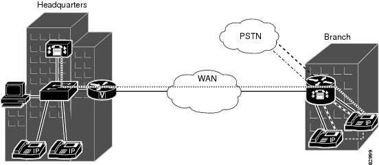
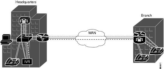
This feature provides voice conferencing at the remote site, without the need for access to the central site (see the figure below).
Transcoding
Transcoding compresses and decompresses voice streams to match endpoint-device capabilities. Transcoding is required when an incoming voice stream is digitized and compressed (by means of a codec) to save bandwidth, but the local device does not support that type of compression. Ideally, all IP telephony devices would support the same codecs, but this is not the case. Rather, different devices support different codecs.
Transcoding is processed by DSPs on the DSP farm; sessions are initiated and managed by Cisco Unified Communications Manager which also refers to transcoders as hardware MTPs.
This feature provides transcoding at the remote site, without the need for access to the central site (see the figure below).
Media Termination Point
A Media Termination Point (MTP) bridges the media streams between two connections allowing Cisco Unified Communications Manager to relay calls that are routed through SIP or H.323 endpoints.
The following MTP resources are supported for Cisco Unified Communications Manager 4.0 (formerly known as Cisco CallManager 4.0) and later releases:
- Software MTP--Software-only implementation that does not use a DSP resource for endpoints using the same codec and the same packetization time.
- Hardware MTP--Hardware-only implementation that uses a DSP resource for endpoints using the same G.711 codec but a different packetization time. The repacketization requires a DSP resource so it cannot be done by software only. Cisco Unified Communications Manager also uses the term software MTP when referring to a hardware MTP.
- Transcoder as MTP--Implementation that uses a DSP resource for endpoints using the same G.711 codec (on both legs) or a mixture of different supported codecs. This functionality is used by Cisco Unified Communications Manager to view the transcoders as usable MTP resources (if they are available in the pool) and enables Cisco Unified Communications Manager to use MTP resources more effectively when a call is deemed to use a transcoder and an MTP resource at the same time.
For MTP and transcoding, the DSP farm supports only two IP streams connected to each other at a time. If more than two streams need connecting, the streams must be connected using conferencing.
Conferencing and Transcoding Features on the NM-HDV2 and NM-HD-1V 2V 2VE
Conferencing
- Cisco Unified Communications Manager meet-me and ad-hoc conferences with up to eight participants each
- Up to 50 eight-party conferences on a single NM-HDV2, up to 24 eight-party conferences on a single NM-HD-2VE, and up to 8 eight-party conferences on a single NM-HD-1V/2V
- Participants using G.711 and G.729 codecs joined in a single conference; no additional transcoding resources are needed to include the disparate codec types
- Easy deployment of conference resources in routers across the network, reducing WAN use and improving voice-network performance
Transcoding
- Transcoding between G.711 and G.729, G.729a, G.729b, G.729ab, GSM FR, and GSM EFR codecs
- Up to 128 transcoding sessions on a single NM-HDV2
MTP
- Software-only implementation that does not use a DSP resource for endpoints with the same codec and the same packetization time.
- Hardware-only implementation using a DSP resource for endpoints with the same G.711 codec but a different packetization time.
Conferencing and Transcoding Features on the NM-HDV
Conferencing
- Cisco Unified Communications Manager meet-me and ad-hoc conferences with up to six participants each
- Up to 15 six-party conferences on a single NM-HDV
- Participants using G.711 and G.729 codecs joined in a single conference; no additional transcoding resources are needed to include the disparate codec types
- Easy deployment of conference resources in routers across the network, reducing WAN use and improving voice-network performance
Transcoding
- Transcoding between G.711 and G.729, G.729a, G.729b, and G.729ab codecs
- Up to 60 transcoding sessions on a single NM-HDV
Conferencing and Transcoding Features on the Cisco 1751 and Cisco 1760
Conferencing
- Cisco Unified Communications Manager meet-me and ad-hoc conferences with up to six participants each
- Up to 5 six-party conferences
- One conference on a single DSP
- Participants using G.711 and G.729 codecs joined in a single conference; no additional transcoding resources are needed to include the disparate codec types
- Easy deployment of conference resources in routers across the network, reducing WAN use and improving voice-network performance
Transcoding
- Transcoding between G.711 and G.729, G.729a, G.729b, and G.729ab codecs
- Up to 16 transcoding sessions on the Cisco 1751
- Up to 20 transcoding sessions on the Cisco 1760
- Two transcoding sessions on a single DSP
Allocation of DSP Resources
You must allocate DSP resources on two levels:
- Within the voice network module, between the DSP farm and your voice trunk group that handles standard voice termination
- Within the DSP farm, between transcoding and voice-conferencing services
- Allocation of DSP Resources Within the Voice Network Module
- Allocation of DSP Resources Within the DSP Farm
- Conferencing and Transcoding Session Capacities
- NM-HDV System Capacities
Allocation of DSP Resources Within the Voice Network Module
You allocate DSP resources either to voice termination of the voice trunk group or to the DSP farm. Occasionally these allocations can conflict.
If you previously allocated DSP resources to voice termination and you now try to configure a DSP farm, you might find that insufficient DSP resources are available. Conversely, if you previously allocated DSP resources to a DSP farm and you now try to configure a trunk group, you might find that insufficient DSP resources are available.
If your requested configuration is rejected, you have two options:
- Insert more DSPs on the voice network module (NM-HDV or NM-HDV2)
- Allocate a different voice network module for either the DSP farm or the trunk group
Allocation of DSP Resources Within the DSP Farm
You should know the following about your system:
- Number of DSPs required to handle your anticipated number of conference calls and transcoding sessions
- Number of DSPs that your system can support
DSP resources can reside in packet-voice DSP modules (PVDMs) installed in voice network modules, for example the NM-HDV2, or directly in the network module, for example the NM-HD-2V. Cisco 2800 series and 3800 series voice gateway routers have onboard DSP resources located on PVDM2s installed directly on the motherboard. Your router supports one or more voice network modules.
The table below lists the total DSPs that are supported on a fully-loaded voice network module.
|
Network Module |
Maximum DSPs per PVDM2/PVDM |
Maximum PVDM2s/PVDMs per Network Module |
Maximum DSPs |
|---|---|---|---|
|
NM-HDV2 |
4 |
4 |
16 |
|
NM-HD-1V/2V |
-- |
-- |
1 |
|
NM-HD-2VE |
-- |
-- |
3 |
|
NM-HDV |
3 |
5 |
15 |
The table below lists the total number of network modules that are supported per router.
|
Router |
NM-HDV2 |
NM-HD-1V, NM-HD-2V, NM-HD-2VE |
NM-HDV |
|---|---|---|---|
|
Cisco 2600 series |
-- |
-- |
1 |
|
Cisco 2600 XM |
1 |
1 |
1 |
|
Cisco 2691 |
1 |
1 |
1 |
|
Cisco 2801 |
-- |
-- |
-- |
|
Cisco 3620 |
-- |
-- |
13 |
|
Cisco 3640 |
-- |
-- |
|
|
Cisco 3660 |
-- |
6 |
6 |
|
Cisco 3725 |
2 |
2 |
2 |
|
Cisco 3745 |
44 |
4 |
|
|
Cisco VG200 |
-- |
-- |
1 |
Conferencing and Transcoding Session Capacities
Each DSP is individually configurable to support either conferencing or transcoding and standard voice termination. The total number of conferencing, transcoding, and voice termination sessions is limited by the capacity of the entire system, which includes the DSPs, hardware platform, physical voice interface, and Cisco Unified Communications Manager.
The tables below list the maximum number of conference calls and transcoding sessions that DSPs can handle, in theory. Actual capacity may be less based on the total system design.
|
Application |
NM-HD-1V/2V (1 DSP) |
NM-HD-2VE (3 DSPs) |
NM-HDV2 (16 DSPs) |
2801/2811 (2 PVDM2-64) |
2821/2851 (3 PVDM2-64) |
3825, 3845 (4 PVDM2-64) |
|---|---|---|---|---|---|---|
|
Conferencing |
||||||
|
G.711 |
8 sessions (64 conferees) |
24 sessions (192 conferees) |
50 sessions (400 conferees) |
50 sessions (400 conferees) |
50 sessions (400 conferees) |
50 sessions (400 conferees) |
|
G.722-64 |
2 sessions (16 conferees) |
6 sessions (48 conferees) |
32 sessions (256 conferees) |
16 sessions (128 conferees) |
24 sessions (192 conferees) |
32 sessions (256 conferees) |
|
G.729 |
2 sessions (16 conferees) |
6 sessions (48 conferees) |
32 sessions (256 conferees) |
16 sessions (128 conferees) |
24 sessions (192 conferees) |
32 sessions (256 conferees) |
|
GSM FR |
-- |
2 sessions (16 conferees) |
14 sessions (112 conferees) |
7 sessions (56 conferees) |
10 sessions (80 conferees) |
14 sessions (112 conferees) |
|
GSM EFR |
-- |
1 session (8 conferees) |
10 sessions (80 conferees) |
5 sessions (40 conferees) |
8 sessions (64 conferees) |
10 sessions (80 conferees) |
|
iLBC |
1 session (8 conferees) |
3 sessions (24 conferees) |
16 sessions (128 conferees) |
8 sessions (64 conferees) |
12 sessions (96 conferees) |
16 sessions (128 conferees) |
|
Transcoding |
||||||
|
G.711 a-law/u-law <-> any (with high complexity codec in dspfarm profile) |
6 sessions |
18 sessions |
96 sessions |
48 sessions |
72 sessions |
96 sessions |
|
G.711 a-law/u-law <-> any (without high complexity codec in dspfarm profile) |
8 sessions |
24 sessions |
128 sessions |
64 sessions |
96 sessions |
128 sessions |
|
G.711 a-law/u-law <-> G.729a/G.729ab/ GSM FR |
8 sessions |
24 sessions |
128 sessions |
64 sessions |
96 sessions |
128 sessions |
|
G.711 a-law/u-law <-> G.729/G.729b/ GSM EFR |
6 sessions |
18 sessions |
96 sessions |
48 sessions |
72 sessions |
96 sessions |
|
G.722-64<-> any |
4 sessions |
12 sessions |
64 sessions |
32 sessions |
48 sessopms |
64 sessions |
|
G.722-64 <-> G.711 |
8 sessions |
24 sessions |
128 sessions |
64 sessions |
96 sessions |
128 sessions |
|
iLBC <-> any |
3 sessions |
9 sessions |
48 sessions |
24 sessions |
36 sessions |
48 sessions |
|
iLBC <-> G.711 |
6 sessions |
18 sessions |
96 sessions |
48 sessions |
72 sessions |
96 sessions |
|
Universal Transcoding (with high complexity codec in dspfarm profile) |
3 sessions |
9 sessions |
48 sessions |
24 sessions |
36 sessions |
48 sessions |
|
Universal Transcoding (without high complexity codec in dspfarm profile) |
4 sessions |
12 sessions |
64 sessions |
32 sessions |
48 sessions |
64 sessions |
|
Voice Termination |
||||||
|
G.711 a-law/u-law |
16 sessions |
48 sessions |
256 sessions |
128 sessions |
192 sessions |
256 sessions |
|
G.726, G.729a, G.729ab, GSM FR |
8 sessions |
24 sessions |
128 sessions |
64 sessions |
96 sessions |
128 sessions |
|
G.729, G.729b, G.723.1, G.728, GSM EFR |
6 sessions |
18 sessions |
96 sessions |
48 sessions |
72 sessions |
96 sessions |
|
Application |
G.711 a-law/u-law |
G.722-64 |
G729 a/ab |
G.729, G.729b |
GSM FR |
GSM EFR |
iLBC |
|---|---|---|---|---|---|---|---|
|
Conferencing |
8 sessions (8 x 8 = 64 conferees) |
2 sessions (8 x 2 = 16 conferees) |
2 sessions (8 x 2 = 16 conferees) |
2 sessions (8 x 2 = 16 conferees) |
-- |
-- |
1 session (1 x 8 = 8 conferees) |
|
Conferencing on PVDM2-8 |
4 sessions (4 x 8 = 32 conferees) |
1 session (1 x 8 = 8 conferees) |
1 session (1 x 8 = 8 conferees) |
1 session (1 x 8 = 8 conferees) |
-- |
-- |
1 session (1 x 8 = 8 conferees) |
|
Hardware MTP |
16 sessions |
-- |
-- |
-- |
-- |
-- |
-- |
|
Transcoding |
8 sessions |
8 sessions |
8 sessions |
6 sessions |
8 sessions |
6 sessions |
8 sessions |
NM-HDV System Capacities
The table below lists the number of transcoding sessions and conference calls supported on the NM-HDV.
|
Device |
Capacity |
|---|---|
|
A single DSP |
4 transcoding sessions |
|
1 conference call with up to 6 participants |
|
|
A single PVDM (3 DSPs) |
12 transcoding sessions |
|
3 conference calls, each with up to 6 participants, for a total of up to 18 participants |
|
|
A fully loaded NM-HDV (5 PVDMs holding 15 DSPs) |
60 transcoding sessions |
|
15 concurrent conference calls, each with up to 6 participants, for a total of up to 90 participants |
Use the following tables to determine the number of PVDMs required to support your DSP needs and whether your router is capable of holding enough NM-HDVs to accommodate these PVDMs:
See the table below if you use either of the following: - See the table beneath the table below if you use 10-ms packetization with VAD disabled
Note | Numbers in the following table represent the number of PVDMs required within a single NM-HDV or NM-HDV-FARM to support the desired configuration. Where numbers are not given, the configuration is not possible using a single NM-HDV. |
|
Transcoding Sessions |
Conference Calls |
|||||||||||||||
|---|---|---|---|---|---|---|---|---|---|---|---|---|---|---|---|---|
|
0 |
1 |
2 |
3 |
4 |
5 |
6 |
7 |
8 |
9 |
10 |
11 |
12 |
13 |
14 |
15 |
|
|
0 |
-- |
1 |
1 |
1 |
2 |
2 |
2 |
3 |
3 |
3 |
4 |
4 |
4 |
5 |
5 |
5 |
|
1-4 |
1 |
1 |
1 |
2 |
2 |
2 |
3 |
3 |
3 |
4 |
4 |
4 |
5 |
5 |
5 |
-- |
|
5-8 |
1 |
1 |
2 |
2 |
2 |
3 |
3 |
3 |
4 |
4 |
4 |
5 |
5 |
5 |
-- |
-- |
|
9-12 |
1 |
2 |
2 |
2 |
3 |
3 |
3 |
4 |
4 |
4 |
5 |
5 |
5 |
-- |
-- |
-- |
|
13-16 |
2 |
2 |
2 |
3 |
3 |
3 |
4 |
4 |
4 |
5 |
5 |
5 |
-- |
-- |
-- |
-- |
|
17-20 |
2 |
2 |
3 |
3 |
3 |
4 |
4 |
4 |
5 |
5 |
5 |
-- |
-- |
-- |
-- |
-- |
|
21-24 |
2 |
3 |
3 |
3 |
4 |
4 |
4 |
5 |
5 |
5 |
-- |
-- |
-- |
-- |
-- |
-- |
|
25-28 |
3 |
3 |
3 |
4 |
4 |
4 |
5 |
5 |
5 |
-- |
-- |
-- |
-- |
-- |
-- |
-- |
|
29-32 |
3 |
3 |
4 |
4 |
4 |
5 |
5 |
5 |
-- |
-- |
-- |
-- |
-- |
-- |
-- |
-- |
|
33-36 |
3 |
4 |
4 |
4 |
5 |
5 |
5 |
-- |
-- |
-- |
-- |
-- |
-- |
-- |
-- |
-- |
|
37-40 |
4 |
4 |
4 |
5 |
5 |
5 |
-- |
-- |
-- |
-- |
-- |
-- |
-- |
-- |
-- |
-- |
|
41-44 |
4 |
4 |
5 |
5 |
5 |
-- |
-- |
-- |
-- |
-- |
-- |
-- |
-- |
-- |
-- |
-- |
|
45-48 |
4 |
5 |
5 |
5 |
-- |
-- |
-- |
-- |
-- |
-- |
-- |
-- |
-- |
-- |
-- |
-- |
|
49-52 |
5 |
5 |
5 |
-- |
-- |
-- |
-- |
-- |
-- |
-- |
-- |
-- |
-- |
-- |
-- |
-- |
|
53-56 |
5 |
5 |
-- |
-- |
-- |
-- |
-- |
-- |
-- |
-- |
-- |
-- |
-- |
-- |
-- |
-- |
|
57-60 |
5 |
-- |
-- |
-- |
-- |
-- |
-- |
-- |
-- |
-- |
-- |
-- |
-- |
-- |
-- |
-- |
Note | Numbers given in the following table represent the number of PVDMs required within a single NM-HDV to support the desired configuration. Where numbers are not given, the configuration is not possible using a single NM-HDV. |
|
Transcoding Sessions |
Conference Calls |
||||||||||
|---|---|---|---|---|---|---|---|---|---|---|---|
|
0 |
1 |
2 |
3 |
4 |
5 |
6 |
7 |
8 |
9 |
10 |
|
|
0 |
-- |
1 |
1 |
1 |
2 |
2 |
2 |
3 |
3 |
3 |
4 |
|
1-4 |
1 |
1 |
1 |
2 |
2 |
2 |
3 |
3 |
3 |
-- |
-- |
|
5-8 |
1 |
1 |
2 |
2 |
2 |
3 |
3 |
3 |
-- |
-- |
-- |
|
9-12 |
1 |
2 |
2 |
2 |
3 |
3 |
3 |
-- |
-- |
-- |
-- |
|
13-16 |
2 |
2 |
2 |
3 |
3 |
-- |
-- |
-- |
-- |
-- |
-- |
|
17-20 |
2 |
2 |
3 |
3 |
-- |
-- |
-- |
-- |
-- |
-- |
-- |
|
21-24 |
2 |
3 |
3 |
-- |
-- |
-- |
-- |
-- |
-- |
-- |
-- |
|
25-28 |
3 |
-- |
-- |
-- |
-- |
-- |
-- |
-- |
-- |
-- |
-- |
|
29-30 |
3 |
-- |
-- |
-- |
-- |
-- |
-- |
-- |
-- |
-- |
-- |
How to Configure Conferencing and Transcoding for Voice Gateway Routers
Determining DSP Resource Requirements
DSPs reside either directly on a voice network module, such as the NM-HD-2VE, on PVDM2s that are installed in a voice network module, such as the NM-HDV2, or on PVDM2s that are installed directly onto the motherboard, such as on the Cisco 2800 and 3800 series voice gateway routers. You must determine the number of PVDM2s or network modules that are required to support your conferencing and transcoding services and install the modules on your router.
1. Determine the number of transcoding sessions and conference calls that your router must support.
2. Determine the number of DSPs that are required to support the transcoding sessions and conference calls. If voice termination is also required, determine the additional DSPs required.
3. Determine the maximum number of network modules that your router can support.
4. Ensure that your requirements fall within router capabilities, taking into account whether your router supports multiple network modules. If necessary, reassess performance requirements.
5. Install PVDM2s and network modules, as needed.
DETAILED STEPS
| Command or Action | Purpose | |
|---|---|---|
| Step 1 | Determine the number of transcoding sessions and conference calls that your router must support. |
Establishes your performance requirements. |
| Step 2 | Determine the number of DSPs that are required to support the transcoding sessions and conference calls. If voice termination is also required, determine the additional DSPs required.
Example: |
Establishes your hardware requirements. See Determining DSP Resource Requirements and Determining DSP Resource Requirements. For example: 8 G.711 conferences and 32 transcoding sessions require 1 PVDM2-64 (4 DSPs) on the NM-HDV2. |
| Step 3 | Determine the maximum number of network modules that your router can support.
Example: |
Establishes your router capabilities. See Determining DSP Resource Requirements. For example: A Cisco 3745 router can support up to 4 NM-HDV2s (provided processor resources are available). |
| Step 4 | Ensure that your requirements fall within router capabilities, taking into account whether your router supports multiple network modules. If necessary, reassess performance requirements. |
Verifies your proposed solution. |
| Step 5 | Install PVDM2s and network modules, as needed. |
Prepares your system for DSP-farm configuration. See the "Connecting Voice Network Modules" chapter in the Cisco Network Modules Hardware Installation Guide , and the Cisco Network Modules and Interface Cards Regulatory Compliance and Safety Information. |
Enabling SCCP on the Cisco Unified Communications Manager Interface
Perform this task to enable SCCP on the local interface that the voice gateway uses to communicate with Cisco Unified Communications Manager.
1.
enable
2.
configure
terminal
3.
sccp
ccm
{ip-address | dns} identifier identifier-number [port port-number] [version version-number]
4.
sccp
local
interface-type
interface-number
5.
sccp
ip
precedence
value
6.
sccp
7.
exit
DETAILED STEPS
Configuring Enhanced Conferencing and Transcoding
Perform the following procedures to configure enhanced conferencing and transcoding on the NM-HDV2, NM-HD-1V, NM-HD-2V, NM-HD-2VE, or PVDM2:
- Configuring a DSP Farm Profile
- Associating a DSP Farm Profile to a Cisco Unified Communications Manager Group
- Modifying Default Settings for SCCP Connection to Cisco Unified Communications Manager
- Verifying DSP Farm Configuration
- Tips for Troubleshooting Conferencing and Transcoding on Voice Gateway Routers
- Troubleshooting DSP-Farm Services
Configuring a DSP Farm Profile
Perform this procedure to define a DSP farm on the NM-HDV2, NM-HD-1V, NM-HD-2V, NM-HD-2VE, or PVDM2. You must configure each conferencing, transcoding, and MTP profile separately.
Note | Because a software-only MTP does not require DSP resources, you can configure a software-only MTP without a voice network module, or on the NM-HDV if you do not enable the dsp services dspfarmcommand for the voice card. |
Requires Cisco IOS Release 12.3(8)T or a later release. Universal transcoding requires Cisco IOS Release 12.4(11)XY or a later release.
1.
enable
2.
configure
terminal
3.
voice-card
slot
4.
dsp
services
dspfarm
5.
exit
6.
dspfarm
profile
profile-identifier
{conference |
mtp |
transcode[universal]}
7.
description
text
8.
codec
codec-type
9.
maximum
sessions
{hardware |
software}
number
10.
associate
application
sccp
11.
no
shutdown
12.
exit
13.
gateway
14.
timer
receive-rtp
seconds
15.
exit
DETAILED STEPS
Associating a DSP Farm Profile to a Cisco Unified Communications Manager Group
Perform this procedure to define a Cisco Unified Communications Manager group and to associate a DSP farm profile with the Cisco Unified Communications Manager group.
This procedure requires Cisco IOS Release 12.3(8)T or later release.
1.
enable
2.
configure
terminal
3.
sccp
ccm
group
group-number
4.
associate
ccm
identifier-number
priority
priority-number
5.
associate
profile
profile-identifier
register
device-name
6.
bind
interface
interface-type
interface-number
7.
description
text
8.
end
DETAILED STEPS
| Command or Action | Purpose | |
|---|---|---|
| Step 1 |
enable
Example: Router> enable |
Enables privileged EXEC mode.
|
| Step 2 |
configure
terminal
Example: Router# configure terminal |
Enters global configuration mode. |
| Step 3 |
sccp
ccm
group
group-number
Example: Router(config)# sccp ccm group 48 |
Creates a Cisco Unified Communications Manager group and enters SCCP Cisco Unified Communications Manager configuration mode. |
| Step 4 |
associate
ccm
identifier-number
priority
priority-number
Example: Router(config-sccp-ccm)# associate ccm 125 priority 2 |
Adds a Cisco Unified Communications Manager server to the Cisco Unified Communications Manager group and establishes its priority within the group.
|
| Step 5 |
associate
profile
profile-identifier
register
device-name
Example: Router(config-sccp-ccm)# associate profile register abgz12345 |
Associates a DSP farm profile to the Cisco Unified Communications Manager group.
|
| Step 6 |
bind
interface
interface-type
interface-number
Example: Router(config-sccp-ccm)# bind interface fastethernet 2:1 |
Binds an interface to the Cisco Unified Communications Manager group. |
| Step 7 |
description
text
Example: Router(config-sccp-ccm)# description boston office |
(Optional) Includes a specific description of the Cisco Unified Communications Manager group. |
| Step 8 |
end
Example: Router(config)# end |
Exits to privileged EXEC mode. |
Modifying Default Settings for SCCP Connection to Cisco Unified Communications Manager
Perform this task to tune the performance of the SCCP connection between the DSP farm and Cisco Unified Communications Manager.
Note | The optimum settings for these commands depend on your platform and individual network characteristics. Modify the defaults to meet your performance requirements. |
1.
enable
2.
configure
terminal
3. sccp ccm group group-number
4.
connect
interval
seconds
5.
connect
retries
number
6.
keepalive
retries
number
7.
keepalive
timeout
seconds
8.
registration
retries
retry-attempts
9.
registration
timeout
seconds
10.
switchover
method
{graceful | immediate}
11.
switchback
method
{graceful
|
guard [timeout value] | immediate
|
uptime uptime-value}
12.
switchback
interval
seconds
13.
end
DETAILED STEPS
| Command or Action | Purpose | |
|---|---|---|
| Step 1 |
enable
Example: Router> enable |
Enables privileged EXEC mode.
|
| Step 2 |
configure
terminal
Example: Router# configure terminal |
Enters global configuration mode. |
| Step 3 |
sccp ccm group group-number Example: Router(config)# sccp ccm group 48 |
Enters SCCP Cisco Unified Communications Manager configuration mode.
|
| Step 4 |
connect
interval
seconds
Example: Router(config-sccp-ccm)# connect interval 1200 |
(Optional) Specifies the amount of time that a DSP farm profile waits before attempting to connect to another Cisco Unified Communications Manager when the current Cisco Unified Communications Manager fails to connect.
|
| Step 5 |
connect
retries
number
Example: Router(config-sccp-ccm)# connect retries 5 |
(Optional) Specifies the number of times that a DSP farm attempts to connect to a Cisco Unified Communications Manager when the current Cisco Unified Communications Manager connections fails.
|
| Step 6 |
keepalive
retries
number
Example: Router(config-sccp-ccm)# keepalive retries 7 |
(Optional) Sets the number of keepalive retries from SCCP to the Cisco Unified Communications Manager.
|
| Step 7 |
keepalive
timeout
seconds
Example: Router(config-sccp-ccm)# keepalive timeout 50 |
(Optional) Sets the number of seconds between keepalive messages from SCCP to the Cisco Unified Communications Manager.
|
| Step 8 |
registration
retries
retry-attempts
Example: Router(config-sccp-ccm)# registration retries 15 |
(Optional) Sets the number of registration retries that SCCP tries to register with the Cisco Unified Communications Manager.
|
| Step 9 |
registration
timeout
seconds
Example: Router(config-sccp-ccm)# registration timeout 8 |
(Optional) Sets the number of seconds between registration messages sent from SCCP to the Cisco Unified Communications Manager.
|
| Step 10 |
switchover
method
{graceful | immediate} Example: Router(config-sccp-ccm)# switchover method graceful |
(Optional) Sets the switchover method that the SCCP client uses when the communication link to the active Cisco Unified Communications Manager fails.
|
| Step 11 |
switchback
method
{graceful
|
guard [timeout value] | immediate
|
uptime uptime-value} Example: Router(config-sccp-ccm)# switchback method graceful |
(Optional) Sets the switchback method to use when the primary or higher priority Cisco Unified Communications Manager becomes available again.
|
| Step 12 |
switchback
interval
seconds
Example: Router(conf-sccp-ccm)# switchback interval 120 |
(Optional) Sets the number of seconds that the DSP farm waits before polling the primary Cisco Unified Communications Manager when the current Cisco Unified Communications Manager fails to connect.
|
| Step 13 |
end
Example: Router(config-sccp-ccm)# end |
Exits to privileged EXEC mode. |
Verifying DSP Farm Configuration
To verify conferencing, transcoding, and MTP services, perform the following steps.
1. Use the show running-config command to display the configuration of the MTP profile, for example:
2.
show
sccp
ccm
group
[group-number]
3.
show
dspfarm
profile
[profile number]
4.
show
dspfarm
all
5.
show
sccp
6.
show
sccp
connections
7.
show
media
resource
status
DETAILED STEPS
| Step 1 |
Use the show running-config command to display the configuration of the MTP profile, for example: Example: Router# show running-config ... sccp local FastEthernet0/0 sccp ccm 10.40.10.10 identifier 10 version 4.0 sccp ! sccp ccm group 48 associate ccm 10 priority 1 associate profile 12 register MTP123456789 associate profile 2 register XCODE123456 ! dspfarm profile 12 mtp codec g711ulaw maximum sessions hardware 4 maximum sessions software 40 associate application SCCP ! | ||
| Step 2 |
show
sccp
ccm
group
[group-number] Use this command to verify the configuration of the Cisco Unified Communications Manager group, for example: Example: Router# show sccp ccm group 48 CCM Group Identifier: 999 Description: None Associated CCM Id: 10, Priority in this CCM Group: 1 Associated Profile: 2, Registration Name: XCODE1234567 Associated Profile: 12, Registration Name: MTP123456789 Registration Retries: 3, Registration Timeout: 10 sec Keepalive Retries: 3, Keepalive Timeout: 30 sec CCM Connect Retries: 3, CCM Connect Interval: 10 sec Switchover Method: GRACEFUL, Switchback Method: GRACEFUL_GUARD Switchback Interval: 10 sec, Switchback Timeout: 7200 sec Signaling DSCP value: default, Audio DSCP value: default | ||
| Step 3 |
show
dspfarm
profile
[profile number] Use this command to verify the configured DSP farm profiles, for example: Example: Router# show dspfarm profile 12 Dspfarm Profile Configuration Profile ID = 12, Service = MTP, Resource ID = 2 Profile Admin State : UP Profile Operation State : ACTIVE Application : SCCP Status : ASSOCIATED Resource Provider : FLEX_DSPRM Status : UP Number of Resource Configured : 14 Number of Resource Available : 14 Hardware Configured Resources 4 Hardware Available Resources 4 Software Resources 10 Codec Configuration Codec : g711ulaw, sa Router# show dspfarm profile 6 Dspfarm Profile Configuration Profile ID = 6, Service = TRANSCODING, Resource ID = 1 Profile Admin State : UP Profile Operation State : ACTIVE Application : SCCP Status : ASSOCIATED Resource Provider : FLEX_DSPRM Status : UP Number of Resource Configured : 4 Number of Resource Available : 4 Codec Configuration Codec : g711ulaw, Maximum Packetization Period : 30 Codec : g711alaw, Maximum Packetization Period : 30 Codec : g729ar8, Maximum Packetization Period : 60 Codec : g729abr8, Maximum Packetization Period : 60 Codec : gsmfr, Maximum Packetization Period : 20 Codec : g729br8, Maximum Packetization Period : 60 Codec : gsmefr, Maximum Packetization Period : 20
| ||
| Step 4 |
show
dspfarm
all
Use this command to verify the status of the DSP farm, for example: Example: Router# show dspfarm all DSPFARM Configuration Information: Admin State: UP, Oper Status: ACTIVE - Cause code: NONE Transcoding Sessions: 0(Avail: 0), Conferencing Sessions: 2 (Avail: 2) Trans sessions for mixed-mode conf: 0 (Avail: 0), RTP Timeout: 600 Connection check interval 600 Codec G729 VAD: ENABLED Total number of active session(s) 0, and connection(s) 0 SLOT DSP CHNL STATUS USE TYPE SESS-ID CONN-ID PKTS-RXED PKTS-TXED 0 0 1 UP FREE conf - - - - 0 0 2 UP FREE conf - - - - 0 0 3 UP FREE conf - - - - 0 0 4 UP FREE conf - - - - 0 0 5 UP FREE conf - - - - 0 0 6 UP FREE conf - - - - | ||
| Step 5 |
show
sccp
Use the show sccp command to verify that the DSP farm is registered, for example: Example:
Router# show sccp
SCCP Admin State: UP
Gateway IP Address: 10.10.100.29, Port Number: 0
IP Precedence: 5
User Masked Codec list:
Call Manager: 10.10.100.51, Port Number: 2000
                Priority: N/A, Version: 4.0, Identifier: 2
Call Manager: 10.10.100.50, Port Number: 2000
                Priority: N/A, Version: 4.0, Identifier: 1

Transcoding Oper State: ACTIVE - Cause Code: NONE
Active Call Manager: 10.10.100.51, Port Number: 2000
TCP Link Status: CONNECTED, Profile Identifier: 10
Reported Max Streams: 6, Reported Max OOS Streams: 0
Supported Codec: g711ulaw, Maximum Packetization Period: 30
Supported Codec: g711alaw, Maximum Packetization Period: 30
Supported Codec: g729ar8, Maximum Packetization Period: 60
Supported Codec: g729abr8, Maximum Packetization Period: 60
Supported Codec: gsmfr, Maximum Packetization Period: 20
Supported Codec: g729br8, Maximum Packetization Period: 60
Supported Codec: rfc2833 dtmf, Maximum Packetization Period: 20

Software MTP Oper State: ACTIVE - Cause Code: NONE
Active Call Manager: 10.10.100.51, Port Number: 2000
TCP Link Status: CONNECTED, Profile Identifier: 20
Reported Max Streams: 176, Reported Max OOS Streams: 0
Supported Codec: g711ulaw, Maximum Packetization Period: 30
Supported Codec: rfc2833 dtmf, Maximum Packetization Period: 20
| ||
| Step 6 |
show
sccp
connections
Use this command to verify the active SCCP connections, for example: Example: Router# show sccp connections sess_id conn_id stype mode codec ripaddr rport sport 16777268 2164263392 mtp recvonly g711u 0.0.0.0 0 17540 Total number of active session(s) 1, and connection(s) 1 | ||
| Step 7 |
show
media
resource
status
Use this command to verify the current media resource status, for example: Example: Router# show media resource status Resource Providers: Resource Provider ID :: FLEX_DSPRM Status :: REGISTERED Service Profiles MTP :: TRANSCODING :: 6 11 CONFERENCING :: 10 Applications : Application ID : SCCP, Status : REGISTERED |
Tips for Troubleshooting Conferencing and Transcoding on Voice Gateway Routers
This section describes techniques for troubleshooting DSP-farm services.
Basic Troubleshooting Procedures
- Verify the Cisco Unified Communications Manager 4.0 (formerly known as Cisco CallManager 4.0) or later.
- Verify that Cisco Unified Communications Manager is properly configured to provision conferencing, transcoding, and MTP resources.
- Organize your Cisco Unified Communications Manager group IDs, device IDs, and DSP farm profile names. Use the show dsp command to verify that the association between SCCP Cisco Unified Communications Manager and the DSP farm profiles match your organizational plan.
- Verify that the VoIP dial peer application exists on the terminating gateway.
- Collect relevant information from debug and show commands, and configuration files before contacting Cisco Technical Support for assistance.
You can clear any of the following by disabling the DSP farm or SCCP: - Active calls
- DSPs
- Active connection to a Cisco Unified Communications Manager
MTP Troubleshooting Tips
- MTP profiles can use only G.711 a-law or G.711 u-law. If you define a profile for a hardware MTP, and you want to change the codec to other than G.711, you must first remove the hardware MTP by using the no maximum sessions hardware command.
- Verify that only one codec is assigned for each MTP profile. To support multiple codecs, you must define a separate MTP profile for each codec.
Troubleshooting DSP-Farm Services
You can troubleshoot performance by performing any of the following steps.
1.
debug
sccp
{all | errors | events | packets | parser}
2.
debug
dspfarm
{all | errors | events | packets}
3.
debug
media
resource
provisioning
{all | errors| events}
DETAILED STEPS
| Command or Action | Purpose | |
|---|---|---|
| Step 1 |
debug
sccp
{all | errors | events | packets | parser} Example: Router# debug sccp all |
(Optional) Sets debugging levels for SCCP and its applications. |
| Step 2 |
debug
dspfarm
{all | errors | events | packets} Example: Router# debug dspfarm all |
(Optional) Sets debugging levels for DSP-farm service. |
| Step 3 |
debug
media
resource
provisioning
{all | errors| events} Example: Router# debug media resource provisioning all |
(Optional) Sets debugging levels for media resource provisioning. |
Configuring Conferencing and Transcoding (NM-HDV)
Perform the following procedures to configure enhanced conferencing and transcoding on the NM-HDV.
Configuring the DSP Farm on the NM-HDV
Perform this task to configure a DSP farm on an NM-HDV.
Note | If you configured a DSP farm in Cisco IOS Release 12.1(5)YH and have now upgraded to Cisco IOS Release 12.2(13)T or later, you must reconfigure the DSP farm, including enabling DSP-farm services on the NM-HDV and specifying maximum session numbers in each category as appropriate. Your previous configuration no longer works. |
1.
enable
2.
configure
terminal
3.
voice-card
slot
4.
dsp
services
dspfarm
5.
exit
6.
dspfarm
confbridge
maximum
sessions
number
7.
dspfarm
transcoder
maximum
sessions
number
8.
dspfarm
9.
exit
DETAILED STEPS
| Command or Action | Purpose | |||
|---|---|---|---|---|
| Step 1 |
enable
Example: Router> enable |
Enables privileged EXEC mode.
| ||
| Step 2 |
configure
terminal
Example: Router# configure terminal |
Enters global configuration mode. | ||
| Step 3 |
voice-card
slot
Example: Router(config)# voice-card 1 |
Enters voice-card configuration mode for the network module on which you want to enable DSP-farm services. | ||
| Step 4 |
dsp
services
dspfarm
Example: Router(config-voicecard)# dsp services dspfarm |
Enables DSP-farm services on the voice card. | ||
| Step 5 |
exit
Example: Router(config-voicecard)# exit |
Returns to global configuration mode. | ||
| Step 6 |
dspfarm
confbridge
maximum
sessions
number
Example: Router(config)# dspfarm confbridge maximum sessions 3 |
Specifies the maximum number of conferencing sessions to be supported by the DSP farm. A DSP can support 1 conference session with up to 6 participants.
| ||
| Step 7 |
dspfarm
transcoder
maximum
sessions
number
Example: Router(config)# dspfarm transcoder maximum sessions 12 |
Specifies the maximum number of transcoding sessions to be supported by the DSP farm. A DSP can support up to 4 transcoding sessions.
| ||
| Step 8 |
dspfarm
Example: Router(config)# dspfarm |
Enables the DSP farm. | ||
| Step 9 |
exit
Example: Router(config)# exit |
Exits global configuration mode. |
Tuning DSP-Farm Performance on the NM-HDV
Use the following optional commands to tune performance.
1.
enable
2.
configure
terminal
3.
sccp
switchback
timeout
guard
seconds
4.
dspfarm
rtp
timeout
seconds
5.
dspfarm
connection
interval
seconds
6.
exit
DETAILED STEPS
| Command or Action | Purpose | |
|---|---|---|
| Step 1 |
enable
Example: Router> enable |
Enables privileged EXEC mode.
|
| Step 2 |
configure
terminal
Example: Router# configure terminal |
Enters global configuration mode. |
| Step 3 |
sccp
switchback
timeout
guard
seconds
Example: Router(config)# sccp switchback timeout guard 180 |
(Optional) Sets the guard timer. |
| Step 4 |
dspfarm
rtp
timeout
seconds
Example: Router(config)# dspfarm rtp timeout 60 |
(Optional) Configures the Real-Time Transport Protocol (RTP) timeout interval for when the error condition "RTP port unreachable" occurs. |
| Step 5 |
dspfarm
connection
interval
seconds
Example: Router(config)# dspfarm connection interval 60 |
(Optional) Specifies how long to monitor RTP inactivity before deleting an RTP stream. |
| Step 6 |
exit
Example: Router(config)# exit |
Exits global configuration mode. |
What to Do Next
Configuring Conferencing and Transcoding (PVDM-256K)
Perform this task to configure a DSP farm for conferencing and transcoding services using the PVDM-256K on the Cisco 1751 or Cisco 1760.
Determine that there are enough DSPs available for conferencing and transcoding services by using the show voice dsp command.
1.
enable
2.
configure
terminal
3.
dspfarm
confbridge
maximum
sessions
number
4.
dspfarm
transcoder
maximum
sessions
number
5.
dspfarm
6.
exit
DETAILED STEPS
| Command or Action | Purpose | |||
|---|---|---|---|---|
| Step 1 |
enable
Example: Router> enable |
Enables privileged EXEC mode.
| ||
| Step 2 |
configure
terminal
Example: Router# configure terminal |
Enters global configuration mode. | ||
| Step 3 |
dspfarm
confbridge
maximum
sessions
number
Example: Router(config)# dspfarm confbridge maximum sessions 3 |
Specifies the maximum number of conferencing sessions to be supported by the DSP farm. A DSP can support 1 conference session with up to 6 participants.
| ||
| Step 4 |
dspfarm
transcoder
maximum
sessions
number
Example: Router(config)# dspfarm transcoder maximum sessions 12 |
Specifies the maximum number of transcoding sessions to be supported by the DSP farm. A DSP can support up to 4 transcoding sessions.
| ||
| Step 5 |
dspfarm
Example: Router(config)# dspfarm |
Enables the DSP farm. | ||
| Step 6 |
exit
Example: Router(config)# exit |
Exits global configuration mode. |
What to Do Next
Configuring Out-of-Band to In-Band DTMF Relay
There are no specific configuration tasks necessary to support the Out-of-Band to In-Band DTMF Relay for Cisco IOS Voice Gateways feature except those described in the following Prerequisites section.
Prerequisites
Hardware
- NM-HDV2, NM-HD-2VE, or onboard PVDM2 (Cisco 2800 series or Cisco 3800 series).
- WS-SVC-CMM-6T1 or WS-SVC-CMM-6E1 port adapter for Cisco Catalyst 6500 series and Cisco 7600 series Communication Media Module (CMM).
Software
- Enable SCCP on the local interface that the MTP resource uses to communicate with Cisco Unified Communications Manager. For instructions, see the Enabling SCCP on the Cisco Unified Communications Manager Interface.
- Configure a DSP farm profile for MTP resources. For instructions, see the Configuring a DSP Farm Profile.
- Associate the MTP profile with the Cisco Unified Communications Manager group. For instructions, see the Associating a DSP Farm Profile to a Cisco Unified Communications Manager Group.
- Configure DTMF relay in the SIP dial peers using the dtmf-relay rtp-nte command.
- Configure DTMF relay in Cisco Unified Communications Manager 4.0 (formerly known as Cisco CallManager 4.0) or later. For information, see the Cisco Unified CallManager 4.0 documentation.
Consider your system requirements when configuring DSP farms and SCCP because the defaults for some commands might not result in expected behavior. In particular, the correct settings for the following commands are platform-specific and depend on your individual network characteristics: - connect interval
- connect retries
- keepalive retries
- keepalive timeout
- sccp registration retries
- sccp registration timeout
- switchback interval
Restrictions
- Multifrequency is supported by MTPs but Cisco Unified Communications Manager does not support it.
- Software MTP supports G.711 codecs only.
Out-of-Band to In-Band DTMF Relay for Cisco IOS Voice Gateways
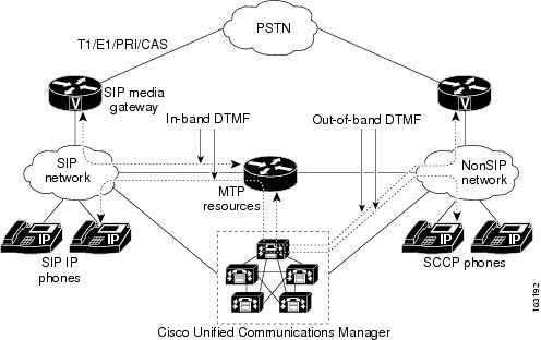
The Out-of-Band to In-Band DTMF Relay for Cisco IOS Voice Gateways feature provides the event processing capability in RFC 2833 that enables DTMF relay communication between SIP devices and nonSIP endpoints using Cisco Unified Communications Manager. RFC 2833 defines a method of transporting tones and other telephony events over Real-Time Transport Protocol (RTP) to ensure DTMF digits are accurately transmitted in a packet environment. A single packet representing a DTMF tone as an event code is passed within an RTP audio stream instead of sending the DTMF tone in-band, where it could be corrupted because of packet loss. When the packet reaches the receiver, it re-creates a tone of the correct frequency and duration.
DTMF detection and generation capabilities are added to the hardware and software MTP. The MTP generates out-of-band SCCP events to Cisco Unified Communications Manager when it detects a DTMF tone. The MTP creates event packets for DTMF digits and inserts the packets into the outgoing RTP stream after receiving an SCCP request from Cisco Unified Communications Manager.
The figure below illustrates the media setup and DTMF tone flow between a SIP network and nonSIP network over a DSP farm MTP.
This feature supports DTMF relay using the following MTP and transcoder resources for Cisco Unified Communications Manager 4.0 (formerly known as Cisco CallManager 4.0):
- Software MTP--Software-only implementation that does not use a DSP resource for endpoints using the same codec and the same packetization time.
- Hardware MTP--Hardware-only implementation that uses a DSP resource for endpoints using the same G.711 codec but a different packetization time. Cisco Unified Communications Manager refers to it also as a software MTP.
- Transcoder--Hardware-only implementation using a DSP resource for endpoints using different codecs. Cisco Unified Communications Manager also refers to it as a hardware MTP.
For MTP and transcoding, the DSP farm supports only two IP streams connected to each other at a time. If more than two streams need connecting, the streams must be connected using conferencing.
Note | For more information on MTPs and transcoders, see the Cisco Unified Communications Manager System Guide Release 4.0(1). |
Configuration Examples for Conferencing and Transcoding
Note | Universal transcoding using the AMR-NB codec in either direction is supported only on the Cisco AS5350XM and Cisco AS5450XM universal gateways. |
- DSP-Farm Services on the NM-HDV2 or PVDM2 Example
- DSP-Farm Services on the NM-HDV Example
- Tuning DSP-Farm Services on the NM-HDV Example
- DSP-Farm Services on the Cisco 1760 Example
- Dut-Band to In-Band DTMF Relay on Cisco 2801 Example
- Out-Band to In-Band DTMF Relay on Cisco 3725 Example
- Universal Transcoding with an Inbox on a Universal Gateway Example
- G.711 to Any Transcoding with an Inbox on a Universal Gateway Example
- Universal and G.711 to Any Transcoding with an Inbox on a Universal Gateway Example
- Universal and G.711 to Any Transcoding with an Inbox on an ISR Example
DSP-Farm Services on the NM-HDV2 or PVDM2 Example
The following example shows a configuration of conferencing and transcoding services on an NM-HDV2 or PVDM2. DSP farm profile 6, which supports transcoding, and profile 10, which supports conferencing are both assigned to Cisco Unified Communications Manager group 988.
Note | This configuration requires Cisco IOS Release 12.3(8)T or later. |
Current configuration : 2661 bytes
!
version 12.3
service timestamps debug datetime msec
service timestamps log datetime msec
no service password-encryption
!
hostname sjl23
!
boot-start-marker
boot-end-marker
!
!
no aaa new-model
ip subnet-zero
!
!
!
ip host boating 223.255.254.254
no ftp-server write-enable
!
voice-card 1
 no dspfarm
 dsp services dspfarm
!
!
voice service voip
 h323
!
!
controller T1 4/1
 framing sf
 crc-threshold 0
 linecode ami
!
controller T1 4/2
 framing sf
 crc-threshold 0
 linecode ami
!
!
!
interface FastEthernet0/0
 ip address 10.4.20.7 255.255.255.0
 no ip mroute-cache
 speed auto
 half-duplex
 no cdp enable
!
interface FastEthernet0/1
 no ip address
 no ip mroute-cache
 shutdown
 duplex auto
 speed auto
 no cdp enable
!
ip default-gateway 10.4.0.1
ip classless
ip route 0.0.0.0 0.0.0.0 FastEthernet0/0
ip route 223.255.254.254 255.255.255.255 10.4.0.1
no ip http server
!
!
no cdp run
!
!
control-plane
!
!
voice-port 1/0/0
!
voice-port 1/0/1
!
!
sccp local FastEthernet0/0
sccp ccm 10.4.20.24 identifier 1 version 4.0
sccp ccm 10.4.20.25 identifier 2 version 4.0
sccp ccm 10.4.20.26 identifier 3 version 4.0
sccp ip precedence 3
sccp
sccp ccm group 48
 associate ccm 1 priority 1
 associate ccm 2 priority 2
 associate ccm 3 priority 3
 associate profile 10 register CFB123456789966
 associate profile 6 register MTP123456789988
 keepalive retries 5
 switchover method immediate
 switchback method immediate
 switchback interval 15
dspfarm profile 6 transcode
 codec g711ulaw
 codec g711alaw
 codec g729ar8
 codec g729abr8
 codec gsmfr
 maximum sessions 4
 associate application SCCP
dspfarm profile 10 conference
 codec g711ulaw
 codec g711alaw
 codec g729ar8
 codec g729abr8
 codec g729r8
 codec g729br8
 maximum sessions 1
 associate application SCCP
!
dial-peer cor custom
!
!
dial-peer voice 200 voip
 destination-pattern 111....
 session target ipv4:10.4.205.24
!
dial-peer voice 2600 voip
 destination-pattern 666....
 session target ipv4:10.4.205.24
 codec g711ulaw
!
dial-peer voice 100 voip
 destination-pattern 5550...
 session target ipv4:10.4.205.24
 codec g711ulaw
!
dial-peer voice 10 pots
 destination-pattern 7770000
 forward-digits 0
!
dial-peer voice 11 pots
 destination-pattern 7771111
!
dial-peer voice 999 voip
 session target ipv4:10.4.205.8
!
gateway
 timer receive-rtp 1200
!
!
line con 0
 exec-timeout 0 0
line aux 0
line vty 0 4
 password test
 login
!
!
end
DSP-Farm Services on the NM-HDV Example
The following sample configuration shows voice conferencing and transcoding are both configured on the same NM-HDV.
Current configuration : 1163 bytes
!
version 12.2
service timestamps debug datetime msec
service timestamps log datetime msec
no service password-encryption
!
hostname router
!
voice-card 1
 dsp services dspfarm
!
ip subnet-zero
!
mta receive maximum-recipients 0
!
controller T1 1/0
 framing sf
 linecode ami
 no yellow generation
 no yellow detection
!
controller T1 1/1
 framing sf
 linecode ami
 no yellow generation
 no yellow detection
!
interface FastEthernet0/0
 ip address 10.10.10.11 255.255.255.0
 load-interval 30
 duplex auto
 speed auto
!
interface FastEthernet0/1
 ip address 10.3.150.139 255.0.0.0
 load-interval 30
 duplex auto
 speed auto
!
ip classless
ip route 192.255.254.254 255.255.255.255 FastEthernet0/1
ip http server
!
call rsvp-sync
!
mgcp profile default
!
sccp local FastEthernet0/0
sccp
sccp ccm 10.10.10.1 priority 1
sccp ccm 10.10.10.2 priority 2
dspfarm transcoder maximum sessions 1
dspfarm confbridge maximum sessions 1
dspfarm
!
voice-port 1/0/0
!
voice-port 1/0/1
!
voice-port 1/1/0
!
voice-port 1/1/1
!
mgcp profile default
!
dial-peer cor custom
!
dial-peer voice 10 pots
 destination-pattern 3140001
 port 1/0/0
!
! Following dial peer is for calls to H.323 end-point 313.... for transcoding.
! Session target is IP address of Cisco Unified Communications Manager.
!
dial-peer voice 100 voip
 destination-pattern 313....
 session target ipv4:10.10.10.1
!
! Following dial peer is for calls to IP Phones for conferencing.
! Session target is IP address of Cisco Unified Communications Manager.
!
dial-peer voice 200 voip
 destination-pattern 700....
 session target ipv4:10.10.10.1
 codec g711alaw
!
line con 0
line aux 0
line vty 0 4
 login
!
end
Tuning DSP-Farm Services on the NM-HDV Example
...
sccp local FastEthernet 0/0
sccp
sccp ccm 10.10.10.1 priority 1 version 3.1+
sccp ccm 10.10.10.2 priority 2
sccp ip precedence 5
sccp switchback timeout guard 180
!
dspfarm confbridge maximum sessions 3
dspfarm rtp timeout 60
dspfarm connection interval 60
dspfarm
DSP-Farm Services on the Cisco 1760 Example
Current configuration :1763 bytes
!
version 12.3
service timestamps debug datetime msec
service timestamps log datetime msec
no service password-encryption
!
hostname c1760
!
boot-start-marker
boot-end-marker
!
logging buffered 40960 debugging
no logging console
!
tdm clock E1 1/0 both export line
tdm clock bri-auto
mmi polling-interval 60
no mmi auto-configure
no mmi pvc
mmi snmp-timeout 180
voice-card 0
!
voice-card 1
!
no aaa new-model
ip subnet-zero
ip cef
!
!
no ip domain lookup
ip multicast-routing
no ftp-server write-enable
isdn switch-type basic-net3
!
!
ccm-manager music-on-hold
!
!
controller E1 1/0
!
!
interface FastEthernet0/0
 ip address 10.1.1.34 255.255.0.0
 ip igmp join-group 172.16.1.10
 speed auto
 no keepalive
!
interface BRI0/0
 no ip address
 isdn switch-type basic-net3
 isdn incoming-voice voice
!
interface BRI0/1
 no ip address
 shutdown
 isdn switch-type basic-net3
!
ip default-gateway 10.5.0.1
ip classless
no ip http server
ip rtcp report interval 2000
!
!
control-plane
!
!
!
voice-port 0/0
!
voice-port 0/1
!
!
sccp local FastEthernet0/0
sccp
sccp ccm 10.1.1.30 priority 1
sccp ccm 10.1.1.0 priority 2
sccp switchback timeout guard 180
!
dspfarm transcoder maximum sessions 4
dspfarm confbridge maximum sessions 1
dspfarm rtp timeout 60
dspfarm connection interval 60
dspfarm
!
!
dial-peer voice 500 pots
 destination-pattern 241760....
 incoming called-number 261760....
 direct-inward-dial
 port 0/0
 prefix 241760
!
dial-peer voice 600 voip
 destination-pattern 261760....
 session target ipv4:10.1.1.30
 incoming called-number 241760....
 playout-delay minimum low
 codec g711ulaw
 no vad
!
gateway
 timer receive-rtcp 5
 timer receive-rtp 1200
!
!
line con 0
 exec-timeout 0 0
line aux 0
line vty 0 4
 login
!
end
Dut-Band to In-Band DTMF Relay on Cisco 2801 Example
In the following configuration, the voice gateway acts as both a H.323 gateway and DSP farm.
Building configuration...
Current configuration :2091 bytes
!
version 12.3
service timestamps debug datetime msec
service timestamps log datetime msec
no service password-encryption
!
hostname 2801_router
!
boot-start-marker
boot-end-marker
!
no logging console
!
no network-clock-participate wic 1
network-clock-participate wic 2
no network-clock-participate wic 3
network-clock-participate wic 4
mmi polling-interval 60
no mmi auto-configure
no mmi pvc
mmi snmp-timeout 180
no aaa new-model
ip subnet-zero
ip cef
!
!
!
no ftp-server write-enable
isdn switch-type primary-net5
voice-card 0
 dsp services dspfarm
!
!
!
controller T1 2/0
 shutdown
 framing esf
 linecode b8zs
!
controller T1 2/1
 framing esf
 linecode b8zs
!
!
!
interface FastEthernet0/0
 ip address 192.168.12.21 255.255.255.0
 duplex auto
 speed auto
!
interface FastEthernet0/1
 no ip address
 shutdown
 duplex auto
 speed auto
!
interface BRI4/0
 no ip address
 isdn switch-type basic-net3
!
interface BRI4/1
 no ip address
 isdn switch-type basic-net3
!
ip classless
ip http server
!
!
!
control-plane
!
!
!
voice-port 3/0
!
voice-port 3/1
!
voice-port 4/0
!
voice-port 4/1
!
!
sccp local FastEthernet0/0
sccp ccm 192.168.12.131 identifier 1 version 4.0
sccp ip precedence 4
sccp
!
sccp ccm group 1
 bind interface FastEthernet0/0
 associate ccm 1 priority 1
 associate profile 2 register amalthea-mtp
 associate profile 1 register amalthea-xcode
 registration retries 20
 registration timeout 30
 keepalive retries 10
 connect retries 30
 connect interval 30
!
dspfarm profile 1 transcode
 description xcode func
 codec g711ulaw
 codec g711alaw
 codec g729ar8
 codec g729abr8
 codec gsmfr
 codec g729r8
 maximum sessions 2
 associate application SCCP
!
dspfarm profile 2 mtp
 codec g711ulaw
 maximum sessions hardware 2
 maximum sessions software 2
 associate application SCCP
!
!
dial-peer voice 1 pots
 destination-pattern 4444
 port 3/0
!
dial-peer voice 2 voip
 destination-pattern 52..
 session target ipv4:192.168.12.131
 dtmf-relay h245-alphanumeric
!
gateway
 timer receive-rtp 1200
!
!
line con 0
line aux 0
line vty 0 4
 login
!
end
Out-Band to In-Band DTMF Relay on Cisco 3725 Example
The following running configuration example shows the MTP device configuration:
Building configuration...
Current configuration : 1435 bytes
!
version 12.3
service timestamps debug uptime
service timestamps log uptime
no service password-encryption
!
hostname router1
!
voice-card 1
 no dspfarm
 dsp services dspfarm
!
voice-card 2
 dspfarm
!
no aaa new-model
ip subnet-zero
!
ip host sample 10.10.10.5
mpls ldp logging neighbor-changes
no ftp-server write-enable
no scripting tcl init
no scripting tcl encdir
!
no voice hpi capture buffer
no voice hpi capture destination
!
interface FastEthernet0/0
 ip address 10.4.118.13 255.255.255.255
 duplex auto
 speed auto
!
interface FastEthernet0/1
 no ip address
 shutdown
 duplex auto
 speed auto
!
ip default-gateway 10.4.0.10
ip classless
ip route 10.0.0.0 255.255.255.255 FastEthernet0/0
ip route 223.255.255.255 255.255.255.255 FastEthernet0/0
!
ip http server
!
sccp local FastEthernet0/0
sccp ccm 10.40.10.10 identifier 10 version 4.0
sccp ccm 10.10.10.51 identifier 20 version 4.0
sccp
!
sccp ccm group 48
 associate ccm 10 priority 1
 associate ccm 20 priority 2
 associate profile 12 register MTP123456789
 associate profile 2 register XCODE123456
!
dspfarm profile 2 transcode
 codec g711ulaw
 codec g711alaw
 codec g729ar8
 codec g729abr8
 codec gsmfr
 maximum sessions 2
 associate application SCCP
!
dspfarm profile 12 mtp
 codec g711ulaw
 maximum sessions hardware 4
 maximum sessions software 40
 associate application SCCP
!
SIP Gateway Example
The following running configuration example shows the SIP gateway configuration for the Out-Band to In-Band DTMF Relay feature:
Building configuration...
Current configuration : 2051 bytes
!
version 12.3
service timestamps debug uptime
service timestamps log uptime
no service password-encryption
!
hostname cisco_sip_gw
!
logging buffered 6000000 debugging
!
voice-card 2
 dspfarm
!
no aaa new-model
ip subnet-zero
!
!
ip domain name cisco.com
ip host sample 10.10.10.5
ip host myhost 10.4.175.2
mpls ldp logging neighbor-changes
no ftp-server write-enable
no scripting tcl init
no scripting tcl encdir
!
!
no voice hpi capture buffer
no voice hpi capture destination
!
!
ccm-manager mgcp
ccm-manager music-on-hold
ccm-manager config server 10.4.175.2
ccm-manager config
!
!
controller T1 2/0
 framing esf
 linecode b8zs
 ds0-group 1 timeslots 1-24 type e&m-wink-start
!
controller T1 2/1
 framing sf
 linecode ami
!
!
!
interface FastEthernet0/0
 ip address 10.4.175.14 255.255.0.0
 duplex auto
 speed auto
!
interface FastEthernet0/1
 no ip address
 shutdown
 duplex auto
 speed auto
!
interface BRI1/0
 no ip address
!
ip default-gateway 10.4.0.1
ip classless
ip route 0.0.0.0 255.255.0.0 FastEthernet0/0
ip route 223.255.254.254 255.255.255.255 FastEthernet0/0
!
ip http server
!
!
voice-port 1/0/0
!
voice-port 1/0/1
!
voice-port 1/1/0
!
voice-port 2/0:1
!
mgcp profile default
!
!
dial-peer voice 1 voip
 destination-pattern 2000
 session protocol sipv2
 session target ipv4:10.4.175.2
 dtmf-relay rtp-nte
 codec g711ulaw
!
dial-peer voice 3 pots
 application mgcpapp
 port 2/0:1
!
dial-peer voice 999201 pots
 application mgcpapp
 port 2/0:1
!
dial-peer voice 2 pots
 destination-pattern 2005
 port 1/0/0
!
dial-peer voice 5 pots
 destination-pattern 2001
 port 1/0/0
!
!
line con 0
line aux 0
line vty 0 4
 login
!
!
end
Universal Transcoding with an Inbox on a Universal Gateway Example
The following example shows a universal transcoding configuration with an inbox on a Cisco Unified Border Element on a universal gateway. Universal gateways include the Cisco AS5350XM and Cisco AS5400XM platforms:
iLBC_UUT1#sh run
Building configuration...
Current configuration : 3244 bytes
!
!
voice-card 5
 dsp services dspfarm
!
voice-card 6
!
voice-card 7
 dsp services dspfarm
!
!
voice service voip
 allow-connections h323 to h323
 allow-connections h323 to sip
 allow-connections sip to h323
 fax protocol t38 ls-redundancy 0 hs-redundancy 0 fallback cisco
 modem passthrough none codec g729r8 pre-ietf
!
!
interface GigabitEthernet0/0
 ip address 10.10.10.2 255.255.0.0
 duplex auto
 speed auto
 negotiation auto
!
interface GigabitEthernet0/1
 ip address 10.20.20.2 255.255.0.0
 duplex auto
 speed auto
 negotiation auto
!
!
sccp local GigabitEthernet0/0
sccp ccm 10.10.10.2 identifier 1
sccp
!
sccp ccm group 1
 associate ccm 1 priority 1
 associate profile 10 register MTPNEWONE
!
dspfarm profile 10 transcode universal
 codec g711ulaw
 codec g711alaw
 codec ilbc
 codec g723r63
 codec g723r53
 codec gsmamr-nb
 codec g729ar8
 codec g729abr8
 maximum sessions 10
 associate application SCCP
!
!
dial-peer voice 10 voip
 destination-pattern 9991...
 session protocol sipv2
 session target ipv4:20.20.20.1

!
dial-peer voice 20 voip
 session target ipv4:10.10.10.1
 incoming called-number 9991...
 codec ilbc
!
!
telephony-service       -------------------------> Only Required for InBox
 sdspfarm units 1
 sdspfarm transcode sessions 128
 sdspfarm tag 1 MTPNEWONE
 ip source-address 10.10.10.2 port 2000
 max-conferences 8 gain -6
 transfer-system full-consult
!
G.711 to Any Transcoding with an Inbox on a Universal Gateway Example
The following example shows the configuration for transcoding for G.711 to any codec with an inbox on a Cisco Unified Border Element on a universal gateway. Universal gateways include the Cisco AS5350XM and Cisco AS5400XM platforms:
iLBC_UUT1#sh run
Building configuration...
Current configuration : 3244 bytes
!
!
voice-card 5
 dsp services dspfarm
!
voice-card 6
!
voice-card 7
 dsp services dspfarm
!
!
voice service voip
 allow-connections h323 to h323
 allow-connections h323 to sip
 allow-connections sip to h323
 fax protocol t38 ls-redundancy 0 hs-redundancy 0 fallback cisco
 modem passthrough none codec g729r8 pre-ietf
!
!
interface GigabitEthernet0/0
 ip address 10.10.10.2 255.255.0.0
 duplex auto
 speed auto
 negotiation auto
!
interface GigabitEthernet0/1
 ip address 10.20.20.2 255.255.0.0
 duplex auto
 speed auto
 negotiation auto
!
!
sccp local GigabitEthernet0/0
sccp ccm 10.10.10.2 identifier 1
sccp
!
sccp ccm group 1
 associate ccm 1 priority 1
 associate profile 20 register traditional
!
!
dspfarm profile 20 transcode
 codec g711ulaw
 codec g711alaw
 codec ilbc
 codec g723r63
 codec g723r53
 codec gsmamr-nb
 codec g729ar8
 codec g729abr8
 maximum sessions 20
 associate application SCCP
!
!
dial-peer voice 10 voip
 destination-pattern 9991...
 session protocol sipv2
 session target ipv4:10.20.20.1
 codec g711ulaw
!
dial-peer voice 20 voip
 session target ipv4:10.10.10.1
 incoming called-number 9991...
 codec ilbc
!
!
telephony-service -------------------------> Only Required for InBox
 sdspfarm units 1
 sdspfarm transcode sessions 128
 sdspfarm tag 1 traditional
 ip source-address 10.10.10.2 port 2000
 max-conferences 8 gain -6
 transfer-system full-consult
!
Universal and G.711 to Any Transcoding with an Inbox on a Universal Gateway Example
The following example shows the configuration for transcoding for both universal and G.711 to any codec with an inbox on a Cisco Unified Border Element on a universal gateway. Universal gateways include the Cisco AS5350XM and Cisco AS5400XM platforms:
iLBC_UUT1#sh run
Building configuration...
!
voice-card 5
 dsp services dspfarm
!
voice-card 6
!
voice-card 7
 dsp services dspfarm
!
voice service voip
 allow-connections h323 to h323
 allow-connections h323 to sip
 allow-connections sip to h323
 fax protocol t38 ls-redundancy 0 hs-redundancy 0 fallback cisco
 modem passthrough none codec g729r8 pre-ietf
!
!
interface GigabitEthernet0/0
 ip address 10.10.10.2 255.255.0.0
 duplex auto
 speed auto
 negotiation auto
!
interface GigabitEthernet0/1
 ip address 10.20.20.2 255.255.0.0
 duplex auto
 speed auto
 negotiation auto
!
!
sccp local GigabitEthernet0/0
sccp ccm 10.10.10.2 identifier 1
sccp
!
sccp ccm group 1
 associate ccm 1 priority 1
 associate profile 20 register traditional
 associate profile 10 register MTPNEWONE
!
dspfarm profile 10 transcode universal
 codec g711ulaw
 codec g711alaw
 codec ilbc
 codec g723r63
 codec g723r53
 codec gsmamr-nb
 codec g729ar8
 codec g729abr8
 maximum sessions 10
 associate application SCCP
!
dspfarm profile 20 transcode
 codec g711ulaw
 codec g711alaw
 codec ilbc
 codec g723r63
 codec g723r53
 codec gsmamr-nb
 codec g729ar8
 codec g729abr8
 maximum sessions 20
 associate application SCCP
!
dial-peer voice 10 voip
 destination-pattern 9991...
 session protocol sipv2
 session target ipv4:10.20.20.1
 codec g711ulaw
!
dial-peer voice 20 voip
 session target ipv4:10.10.10.1
 incoming called-number 9991...
 codec ilbc
!
!
telephony-service -------------------------> Only Required for InBox
 sdspfarm units 2
 sdspfarm transcode sessions 128
 sdspfarm tag 1 traditional
 sdspfarm tag 2 MTPNEWONE
 ip source-address 10.10.10.2 port 2000
 max-conferences 8 gain -6
 transfer-system full-consult
!
Universal and G.711 to Any Transcoding with an Inbox on an ISR Example
The following example shows the configuration for transcoding for both universal and G.711 to any codec with an inbox on a Cisco Unified Border Element on an integrated services router. Integrated services routers include the Cisco 2800 and Cisco 3800 platforms:
crosby-3845#
!
voice-card 0
 no dspfarm
 dsp services dspfarm  !
!
voice service voip
 allow-connections h323 to h323
!
interface GigabitEthernet0/0
 ip address 10.3.65.102 255.255.0.0
 duplex auto
 speed auto
 media-type rj45
!
!
sccp local GigabitEthernet0/0
sccp ccm 10.3.65.102 identifier 1
sccp
!
sccp ccm group 1
 associate ccm 1 priority 1
 associate profile 20 register MTP000ABCD
 associate profile 10 register OLDONE
 keepalive retries 5
 switchback method immediate
!
dspfarm profile 10 transcode  ------------> for g711 to any
 codec g711ulaw
 codec g711alaw
 codec ilbc
 codec g723r63
 codec g723r53
 codec gsmamr-nb
 codec g729ar8
 codec g729abr8
 maximum sessions 10
 associate application SCCP
!
dspfarm profile 20 transcode universal  --------------> for Any to Any
 codec g711ulaw
 codec g711alaw
 codec ilbc
 codec g723r63
 codec g723r53
 codec gsmamr-nb
 codec g729ar8
 codec g729abr8
 maximum sessions 2
 associate application SCCP
!
!
dial-peer voice 10 voip
 destination-pattern 2...
 session target ipv4:1.3.65.12
 codec ilbc
!
dial-peer voice 11 voip
 destination-pattern 1...
 session target ipv4:10.3.65.11
 codec g711ulaw
!
!
telephony-service   -----------> Minimum config for telephony is required for InBox
 ip source-address 10.3.65.102 port 2000
 sdspfarm units 2
 sdspfarm transcode sessions 30
 sdspfarm tag 1 MTP000ABCD
 sdspfarm tag 2 OLDONE
 max-ephones 20
 max-dn 20
 max-conferences 12 gain -6
 transfer-system full-consult
 create cnf-files version-stamp 7960 Sep 27 2006 20:39:40
Where to Go Next
- To enable MGCP on a Cisco IOS gateway, see Configuring MGCP Gateway Support for Cisco Unified Communications Manager, page 23 .
- To enable MGCP PRI backhaul support, see "Configuring MGCP PRI Backhaul and T1 CAS Support for Cisco Unified Communications Manager" on page 113 .
- To enable MGCP BRI backhaul support, see "Configuring MGCP-Controlled Backhaul of BRI Signaling in Conjunction with Cisco Unified Communications Manager" on page 129 .
- To download region-specific tones and the associated frequencies, amplitudes, and cadences, see "Configuring Tone Download to MGCP Gateways" on page 145 .
Additional References
- "Overview of Cisco Unified Communications Manager and Cisco IOS Interoperability" on page 13 --Describes basics of underlying technology and lists related documents.
- "Conference Bridges" chapter in the Cisco Unified CallManager System Guide , Release 4.0(1)--Overview of conference devices in Cisco Unified CallManager 4.0.
- "Conference Bridge Configuration" chapter in the Cisco Unified CallManager Administration Guide, Release 4.0(1)--Describes how to configure conference bridges in Cisco Unified CallManager 4.0.
- "Transcoders" chapter in the Cisco Unified CallManager System Guide --Overview of transcoder devices in Cisco Unified CallManager 4.0.
- "Transcoder Configuration" chapter in the Cisco Unified CallManager Administration Guide --Describes how to configure transcoders in Cisco Unified CallManager 4.0.
- IP Communications High-Density Digital Voice/Fax Network Module feature document--Describes how to configure support for the NM-HDV2 in Cisco IOS gateways.
- "Connecting Voice Network Modules" chapter in the Cisco Network Modules Hardware Installation Guide --Describes how to install the voice network modules.