- MPLS VPN Inter-AS with ASBRs Exchanging VPN-IPv4 Addresses
- MPLS VPN Inter-AS with ASBRs Exchanging IPv4 Routes and MPLS Labels
- MPLS VPN Multipath Support for Inter-AS VPNs
- MPLS VPN--Inter-AS Option AB
- MPLS VPN Carrier Supporting Carrier Using LDP and an IGP
- MPLS VPN Carrier Supporting Carrier with BGP
- MPLS VPN Load Balancing Support for Inter-AS and CSC VPNs
- MPLS VPN eBGP Multipath Support for CSC and Inter-AS MPLS VPNs
- MPLS VPN Explicit Null Label Support with BGP IPv4 Label Session
Contents
- MPLS VPN Inter-AS with ASBRs Exchanging VPN-IPv4 Addresses
- Finding Feature Information
- Prerequisites for MPLS VPN Inter-AS with ASBRs Exchanging VPN-IPv4 Addresses
- Restrictions for MPLS VPN Inter-AS with ASBRs Exchanging VPN-IPv4 Addresses
- Information About MPLS VPN Inter-AS with ASBRs Exchanging VPN-IPv4 Addresses
- MPLS VPN Inter-AS Introduction
- Benefits of MPLS VPN Inter-AS
- Use of Inter-AS with ASBRs Exchanging VPN-IPv4 Addresses
- Information Exchange in an MPLS VPN Inter-AS with ASBRs Exchanging VPN-IPv4 Addresses
- Transmission of Information in an MPLS VPN Inter-AS with ASBRs Exchanging VPN-IPv4 Addresses
- Exchange of VPN Routing Information in an MPLS VPN Inter-AS with ASBRs Exchanging VPN-IPv4 Addresses
- Packet Forwarding Between MPLS VPN Inter-AS Systems with ASBRs Exchanging VPN-IPv4 Addresses
- Use of a Confederation for MPLS VPN Inter-AS with ASBRs Exchanging VPN-IPv4 Addresses
- How to Configure MPLS VPN Inter-AS with ASBRs Exchanging VPN-IPv4 Addresses
- Configuring the ASBRs to Exchange VPN-IPv4 Addresses
- Configuring EBGP Routing to Exchange VPN Routes Between Subautonomous Systems in a Confederation
- Verifying Inter-AS with ASBRs Exchanging VPN-IPv4 Addresses
- Configuration Examples for MPLS VPN Inter-AS with ASBRs Exchanging VPN-IPv4 Addresses
- Example: Configuring MPLS VPN Inter-AS with ASBRs Exchanging VPN-IPv4 Addresses
- Example: Configuration for Autonomous System 1 CE1
- Example: Configuration for Autonomous System 1 PE1
- Example: Configuration for Autonomous System 1 P1
- Example: Configuration for Autonomous System 1 EBGP1
- Example: Configuration for Autonomous System 2 EBGP2
- Example: Configuration for Autonomous System 2 P2
- Example: Configuration for Autonomous System 2 PE2
- Example: Configuration for Autonomous System 2 CE2
- Example: Configuring MPLS VPN Inter-AS with ASBRs Exchanging VPN-IPv4 Addresses in a Confederation
- Example: Configuration for Autonomous System 1 CE1
- Example: Configuration for Autonomous System 1 PE1
- Example: Configuration for Autonomous System 1 P1
- Example: Configuration for Autonomous System 1 ASBR1
- Example: Configuration for Autonomous System 2 ASBR2
- Example: Configuration for Autonomous System 2 P2
- Example: Configuration for Autonomous System 2 PE2
- Example: Configuration for Autonomous System 2 CE2
- Additional References
- Feature Information for MPLS VPN Inter-AS with ASBRs Exchanging VPN-IPv4 Addresses
MPLS VPN Inter-AS with ASBRs Exchanging VPN-IPv4 Addresses
The Multiprotocol Label Switching (MPLS) VPN Inter-AS with Autonomous System Boundary Routers (ASBRs) Exchanging VPN-IPv4 Addresses feature allows a MPLS VPN to span service providers and autonomous systems. This module explains how to enable ASBRs to use Exterior Border Gateway Protocol (EBGP) to exchange IPv4 Network Layer Reachability Information (NLRI) in the form of VPN-IPv4 addresses.
- Finding Feature Information
- Prerequisites for MPLS VPN Inter-AS with ASBRs Exchanging VPN-IPv4 Addresses
- Restrictions for MPLS VPN Inter-AS with ASBRs Exchanging VPN-IPv4 Addresses
- Information About MPLS VPN Inter-AS with ASBRs Exchanging VPN-IPv4 Addresses
- How to Configure MPLS VPN Inter-AS with ASBRs Exchanging VPN-IPv4 Addresses
- Configuration Examples for MPLS VPN Inter-AS with ASBRs Exchanging VPN-IPv4 Addresses
- Additional References
- Feature Information for MPLS VPN Inter-AS with ASBRs Exchanging VPN-IPv4 Addresses
Finding Feature Information
Your software release may not support all the features documented in this module. For the latest caveats and feature information, see Bug Search Tool and the release notes for your platform and software release. To find information about the features documented in this module, and to see a list of the releases in which each feature is supported, see the feature information table at the end of this module.
Use Cisco Feature Navigator to find information about platform support and Cisco software image support. To access Cisco Feature Navigator, go to www.cisco.com/go/cfn. An account on Cisco.com is not required.
Prerequisites for MPLS VPN Inter-AS with ASBRs Exchanging VPN-IPv4 Addresses
Before you configure Exterior Border Gateway Protocol (EBGP) routing between autonomous systems or subautonomous systems in an Multiprotocol Label Switching (MPLS) VPN, ensure that you have properly configured all MPLS VPN routing instances and sessions. The configuration tasks outlined in this section build from those configuration tasks. Perform the following tasks as described in the Configuring MPLS Layer 3 VPNs module: - Define VPN routing instances
- Configure BGP routing sessions in the MPLS core
- Configure provider-edge-provider-edge (PE-to-PE) routing sessions in the MPLS core
- Configure BGP provider-edge-customer-edge (PE-to-CE) routing sessions
- Configure a VPN-IPv4 EBGP session between directly connected Autonomous System Boundary Routers (ASBRs)
Restrictions for MPLS VPN Inter-AS with ASBRs Exchanging VPN-IPv4 Addresses
Multihop VPN-IPv4 Exterior Border Gateway Protocol (EBGP) is not supported.
Information About MPLS VPN Inter-AS with ASBRs Exchanging VPN-IPv4 Addresses
- MPLS VPN Inter-AS Introduction
- Benefits of MPLS VPN Inter-AS
- Use of Inter-AS with ASBRs Exchanging VPN-IPv4 Addresses
- Information Exchange in an MPLS VPN Inter-AS with ASBRs Exchanging VPN-IPv4 Addresses
MPLS VPN Inter-AS Introduction
An autonomous system is a single network or group of networks that is controlled by a common system administration group and that uses a single, clearly defined routing protocol.
As VPNs grow, their requirements expand. In some cases, VPNs need to reside on different autonomous systems in different geographic areas. Also, some VPNs need to extend across multiple service providers (overlapping VPNs). Regardless of the complexity and location of the VPNs, the connection between autonomous systems must be seamless to the customer.
Benefits of MPLS VPN Inter-AS
An MultiprotocolLabel Switching (MPLS) VPN Inter-AS provides the following benefits:
- Allows a VPN to cross more than one service provider backbone: Service providers running separate autonomous systems can jointly offer MPLS VPN services to the same customer. A VPN can begin at one customer site and traverse different VPN service provider backbones before arriving at another site of the same customer. Previously, MPLS VPN could traverse only a single Border Gateway Protocol (BGP) autonomous system service provider backbone. This feature allows multiple autonomous systems to form a continuous (and seamless) network between customer sites of a service provider.
- Allows a VPN to exist in different areas: A service provider can create a VPN in different geographic areas. Having all VPN traffic flow through one point (between the areas) allows for better rate control of network traffic between the areas.
- Allows confederations to optimize Internal Border Gateway Protocol (IBGP) meshing: IBGP meshing in an autonomous system is more organized and manageable. An autonomous system can be divided into multiple, separate subautonomous systems and then classify them into a single confederation (even though the entire VPN backbone appears as a single autonomous system). This capability allows a service provider to offer MPLS VPNs across the confederation because it supports the exchange of labeled VPN-IPv4 Network Layer Reachability Information (NLRI) between the subautonomous systems that form the confederation.
Use of Inter-AS with ASBRs Exchanging VPN-IPv4 Addresses
Separate autonomous systems from different service providers can communicate by exchanging IPv4 Network Layer Reachability Information (NLRI) in the form of VPN-IPv4 addresses. The Autonomous System Border Routers (ASBRs) use Exterior Border Gateway Protocol (EBGP) to exchange network reachability information. Then an Interior Gateway Protocol (IGP) distributes the network layer information for VPN-IPv4 prefixes throughout each VPN and each autonomous system. Routing information uses the following protocols:
- Within an autonomous system, routing information is shared using an IGP.
- Between autonomous systems, routing information is shared using an EBGP. An EBGP allows a service provider to set up an interdomain routing system that guarantees the loop-free exchange of routing information between separate autonomous systems.
The primary function of an EBGP is to exchange network reachability information between autonomous systems, including information about the list of autonomous system routes. The autonomous systems use EBGP border edge devices to distribute the routes, which include label switching information. Each border edge device rewrites the next hop and labels. See the Information Exchange in an MPLS VPN Inter-AS with ASBRs Exchanging VPN-IPv4 Addresses section for more information.
Interautonomous system configurations supported in an MPLS VPN are as follows:
- Interprovider VPN-- MPLS VPNs that include two or more autonomous systems, connected by separate border edge devices. The autonomous systems exchange routes using EBGP. No IGP or routing information is exchanged between the autonomous systems.
- BGP confederations-- MPLS VPNs that divide a single autonomous system into multiple subautonomous systems, and classify them as a single, designated confederation. The network recognizes the confederation as a single autonomous system. The peers in the different autonomous systems communicate over EBGP sessions; however, they can exchange route information as if they were IBGP peers.
Information Exchange in an MPLS VPN Inter-AS with ASBRs Exchanging VPN-IPv4 Addresses
This section contains the following topics:
- Transmission of Information in an MPLS VPN Inter-AS with ASBRs Exchanging VPN-IPv4 Addresses
- Exchange of VPN Routing Information in an MPLS VPN Inter-AS with ASBRs Exchanging VPN-IPv4 Addresses
- Packet Forwarding Between MPLS VPN Inter-AS Systems with ASBRs Exchanging VPN-IPv4 Addresses
- Use of a Confederation for MPLS VPN Inter-AS with ASBRs Exchanging VPN-IPv4 Addresses
Transmission of Information in an MPLS VPN Inter-AS with ASBRs Exchanging VPN-IPv4 Addresses
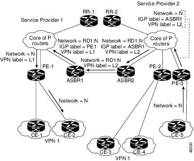
The figure below illustrates an Multiprotocol Label Switching (MPLS) VPN consisting of two separate autonomous systems. Each autonomous system operates under different administrative control and runs a different Interior Gateway Protocol (IGP). Service providers exchange routing information through Exterior Border Gateway Protocol (EBGP) border edge devices (ASBR1, ASBR2).
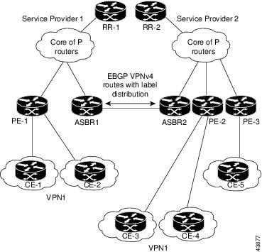
This configuration uses the following process to transmit information:
1. The provider edge device (PE-1) assigns a label for a route before distributing that route. The PE device uses the multiprotocol extensions of Border Gateway Protocol (BGP) to transmit label mapping information. The PE device distributes the route as a VPN-IPv4 address. The address label and the VPN identifier are encoded as part of the IPv4 Network Layer Reachability Information (NLRI).
2. The two route reflectors (RR-1 and RR-2) reflect VPN-IPv4 internal routes within the autonomous system. The border edge devices (ASBR1 and ASBR2) of the autonomous systems advertise the VPN-IPv4 external routes.
3. The EBGP border edge device (ASBR1) redistributes the route to the next autonomous system (ASBR2). ASBR1 specifies its own address as the value of the EBGP next-hop attribute and assigns a new label. The address ensures the following:
4. The EBGP border edge device (ASBR2) redistributes the route in one of the following ways, depending on its configuration:
DETAILED STEPS
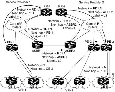
Exchange of VPN Routing Information in an MPLS VPN Inter-AS with ASBRs Exchanging VPN-IPv4 Addresses
Autonomous systems exchange VPN routing information (routes and labels) to establish connections. To control connections between autonomous systems, the provider edge (PE) devices and Exterior Border Gateway Protocol (EBGP) border edge devices maintain a Label Forwarding Information Base (LFIB). The LFIB manages the labels and routes that the PE devices and EBGP border edge devices receive during the exchange of VPN information.
The figure below illustrates the exchange of VPN route and label information between autonomous systems. The autonomous systems use the following conditions to exchange VPN routing information:
Routing information includes: - An RD1: route distinguisher is part of a destination network address. It makes the VPN-IPv4 route globally unique in the VPN service provider environment.
- The Autonomous System Border Routers (ASBRs) are configured to change the next-hop (next hop-self) when sending VPN-IPv4 Network Layer Reachability Information (NLRI) to the Internal Border Gateway Protocol (IBGP) neighbors. Therefore, the ASBRs must allocate a new label when they forward the NLRI to the IBGP neighbors.
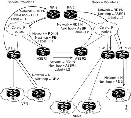
The figure below illustrates the exchange of VPN route and label information between autonomous systems. The only difference is that ASBR2 is configured with the redistribute connected command, which propagates the host routes to all PEs. The redistribute connected command is necessary because ASBR2 is not configured to change the next-hop address.
Packet Forwarding Between MPLS VPN Inter-AS Systems with ASBRs Exchanging VPN-IPv4 Addresses
The figure below illustrates how packets are forwarded between autonomous systems in an interprovider network using the following packet forwarding method.
Packets are forwarded to their destination by means of Multiprotocol Label Switching (MPLS). Packets use the routing information stored in the Label Forwarding Information Base (LFIB) of each provider edge (PE) device and Exterior Border Gateway Protocol (EBGP) border edge device.
The service provider VPN backbone uses dynamic label switching to forward labels.
Each autonomous system uses standard multilevel labeling to forward packets between the edges of the autonomous system devices (for example, from CE-5 to PE-3). Between autonomous systems, only a single level of labeling is used, corresponding to the advertised route.
A data packet carries two levels of labels when traversing the VPN backbone:
- The first label (IGP route label) directs the packet to the correct PE device or EBGP border edge device. (For example, the Interior Gateway Protocol (IGP) label of ASBR2 points to the ASBR2 border edge device.)
- The second label (VPN route label) directs the packet to the appropriate PE device or EBGP border edge device.
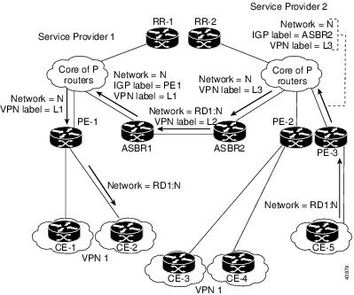
The figure below shows the same packet forwarding method as described in the figure above, except the EBGP device (ASBR1) forwards the packet without reassigning it a new label.
Use of a Confederation for MPLS VPN Inter-AS with ASBRs Exchanging VPN-IPv4 Addresses
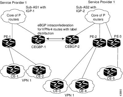
A confederation is a collection of multiple subautonomous systems that are grouped together. A confederation reduces the total number of peer devices in an autonomous system. A confederation divides an autonomous system into subautonomous systems and assigns a confederation identifier to the autonomous systems. A VPN can span service providers running in separate autonomous systems or in multiple subautonomous systems that form a confederation.
In a confederation, each subautonomous system is fully meshed with other subautonomous systems. The subautonomous systems communicate using an Interior Gateway Protocol (IGP), such as Open Shortest Path First (OSPF) or Intermediate System-to-Intermediate System (IS-IS). Each subautonomous system also has an Exterior Border Gateway Protocol (EBGP) connection to the other subautonomous systems. The confederation EBGP (CEBGP) border edge devices forward next-hop-self addresses between the specified subautonomous systems. The next-hop-self address forces the Border Gateway Protocol (BGP) to use a specified address as the next hop rather than letting the protocol choose the next hop.
You can configure a confederation with separate subautonomous systems in either of two ways:
- You can configure a device to forward next-hop-self addresses between only the CEBGP border edge devices (both directions). The subautonomous systems (IBGP peers) at the subautonomous system border do not forward the next-hop-self address. Each subautonomous system runs as a single IGP domain. However, the CEBGP border edge device addresses are known in the IGP domains.
- You can configure a device to forward next-hop-self addresses between the CEBGP border edge devices (both directions) and within the IBGP peers at the subautonomous system border. Each subautonomous system runs as a single IGP domain but also forwards next-hop-self addresses between the PE devices in the domain. The CEBGP border edge device addresses are known in the IGP domains.
The figure below illustrates a typical MPLS VPN confederation configuration. In this confederation configuration:
- The two CEBGP border edge devices exchange VPN-IPv4 addresses with labels between the two subautonomous systems.
- The distributing device changes the next-hop addresses and labels and uses a next-hop-self address.
- IGP-1 and IGP-2 know the addresses of CEBGP-1 and CEBGP-2.
In this confederation configuration:
- CEBGP border edge devices function as neighboring peers between the subautonomous systems. The subautonomous systems use EBGP to exchange route information.
- Each CEBGP border edge device (CEBGP-1, CEBGP-2) assigns a label for the route before distributing the route to the next subautonomous system. The CEBGP border edge device distributes the route as a VPN-IPv4 address by using the multiprotocol extensions of BGP. The label and the VPN identifier are encoded as part of the IPv4 Network Layer Reachability Information (NLRI).
- Each provider edge (PE) and CEBGP border edge device assigns its own label to each VPN-IPv4 address prefix before redistributing the routes. The CEBGP border edge devices exchange VPN-IPv4 addresses with the labels. The next-hop-self address is included in the label (as the value of the EBGP next-hop attribute). Within the subautonomous systems, the CEBGP border edge device address is distributed throughout the IBGP neighbors, and the two CEBGP border edge devices are known to both confederations.
How to Configure MPLS VPN Inter-AS with ASBRs Exchanging VPN-IPv4 Addresses
- Configuring the ASBRs to Exchange VPN-IPv4 Addresses
- Configuring EBGP Routing to Exchange VPN Routes Between Subautonomous Systems in a Confederation
- Verifying Inter-AS with ASBRs Exchanging VPN-IPv4 Addresses
Configuring the ASBRs to Exchange VPN-IPv4 Addresses
To configure an Exterior Border Gateway Protocol (EBGP) Autonomous System Border Router (ASBR) to exchange VPN-IPv4 routes with another autonomous system, perform this task.
 Note | Issue the redistribute connected subnets command in the Interior Gateway Protocol (IGP) configuration portion of the device to propagate host routes for VPN-IPv4 EBGP neighbors to other devices and provider edge devices. Alternatively, you can specify the next-hop-self address when you configure Internal Border Gateway Protocol (IBGP) neighbors. |
1.
enable
2.
configure terminal
3.
router bgp
as-number
4.
no bgp default route-target filter
5.
address-family vpnv4 [unicast]
6.
neighbor
peer-group-name
remote-as
as-number
7.
neighbor
peer-group-name
activate
8.
exit-address-family
9.
end
DETAILED STEPS
Configuring EBGP Routing to Exchange VPN Routes Between Subautonomous Systems in a Confederation
Perform this task to configure EBGP routing to exchange VPN routes between subautonomous systems in a confederation.
Note | To ensure that the host routes for VPN-IPv4 EBGP neighbors are propagated (by means of the IGP) to the other devices and provider edge devices, specify the redistribute connected command in the IGP configuration portion of the CEBGP device. If you are using OSPF, make sure that the OSPF process is not enabled on the CEBGP interface where the “redistribute connected” subnet exists. |
Note | In this confederation, subautonomous system IGP domains must know the addresses of CEBGP-1 and CEBGP-2. If you do not specify a next-hop-self address as part of the router configuration, ensure that the addresses of all PE devices in the subautonomous system are distributed throughout the network, not just the addresses of CEBGP-1 and CEBGP-2. |
1.
enable
2.
configure terminal
3.
router bgp
sub-autonomous-system
4.
bgp confederation identifier
as-number
5.
bgp conferderation peers
sub-autonomous-system
6.
no bgp default route-target filter
7.
address-family vpnv4 [unicast]
8.
neighbor
peer-group-name
remote-as
as-number
9.
neighbor
peer-group-name
next-hop-self
10.
neighbor
peer-group-name
activate
11.
exit-address-family
12.
end
DETAILED STEPS
Verifying Inter-AS with ASBRs Exchanging VPN-IPv4 Addresses
Perform this task to display the VPN-IPv4 Label Forwarding Information Base (LFIB) entries.
1.
enable
2.
show ip bgp vpnv4 {all |
rd
route-distinguisher |
vrf
vrf-name} [summary] [labels]
3.
show mpls forwarding-table [network {mask |
length} |
labels
label [-label] |
interface
interface |
next-hop
address |
lsp-tunnel [tunnel-id]] [vrf
vrf-name] [detail]
4.
disable
DETAILED STEPS
Configuration Examples for MPLS VPN Inter-AS with ASBRs Exchanging VPN-IPv4 Addresses
- Example: Configuring MPLS VPN Inter-AS with ASBRs Exchanging VPN-IPv4 Addresses
- Example: Configuring MPLS VPN Inter-AS with ASBRs Exchanging VPN-IPv4 Addresses in a Confederation
Example: Configuring MPLS VPN Inter-AS with ASBRs Exchanging VPN-IPv4 Addresses
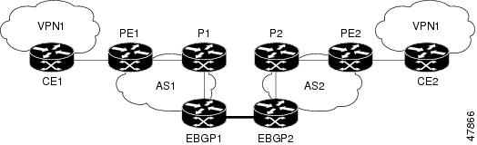
The network topology in the figure below shows two autonomous systems, which are configured as follows:
- Autonomous system 1 (AS1) includes provider edge 1 (PE1), P1, and Exterior Border Gateway Protocol 1(EBGP1). The Interior Gateway Protocol (IGP) is Open Shortest Path First(OSPF).
- Autonomous system 2 (AS2) includes PE2, P2, and EBGP2. The IGP is Intermediate System to Intermediate System (IS-IS).
- Customer edge 1 (CE1) and CE2 belong to the same VPN, which is called VPN1.
- The P devices are route reflectors.
- EBGP1 is configured with the redistribute connected subnets command.
- EBGP2 is configured with the neighbor next-hop-self command.
- Example: Configuration for Autonomous System 1 CE1
- Example: Configuration for Autonomous System 1 PE1
- Example: Configuration for Autonomous System 1 P1
- Example: Configuration for Autonomous System 1 EBGP1
- Example: Configuration for Autonomous System 2 EBGP2
- Example: Configuration for Autonomous System 2 P2
- Example: Configuration for Autonomous System 2 PE2
- Example: Configuration for Autonomous System 2 CE2
Example: Configuration for Autonomous System 1 CE1
The following example shows how to configure CE1 in VPN1 in a topology with two autonomous systems:
interface Loopback1
 ip address 10.1.0.4 255.0.0.0
!
interface GigabitEthernet0/0/0
 		no ip address
 encapsulation frame-relay
 frame-relay intf-type dce
!
interface GigabitEthernet0/5/3 point-to-point
  ip address 10.1.0.2 255.0.0.0
 frame-relay interface-dlci 22
!
router ospf 1
 network 192.168.3.0 255.255.0.0 area 0
Example: Configuration for Autonomous System 1 PE1
The following example shows how to configure PE1 in AS1 in a topology with two autonomous systems:
ip cef
!
ip vrf V1
 rd 1:105
 route-target export 1:100
 route-target import 1:100
!
interface GigabitEthernet0/0/0
 no ip address
 encapsulation frame-relay
 no fair-queue
 clockrate 2000000
!
interface GigabitEthernet0/0/0.3 point-to-point
 ip vrf forwarding V1
 ip address 192.168.2.4 255.255.0.0
 frame-relay interface-dlci 22
!
interface GigabitEthernet0/5/3
 ip address 192.168.3.5 255.255.0.0
 tag-switching ip
!
router ospf 1
 log-adjacency-changes
 network 192.168.41.0 255.255.0.0 area 0
!
router ospf 10 vrf V1
 log-adjacency-changes
 redistribute bgp 1 metric 100 subnets
 network 192.168.41.0 255.255.0.0 area 0
!
router bgp 1
 no synchronization
 neighbor 1 peer-group
 neighbor 1 remote-as 1
 neighbor 1 update-source Loopback0
 neighbor 192.168.11.10 peer-group R
 no auto-summary
 !
 address-family ipv4 vrf V1
  redistribute ospf 10
  no auto-summary
  no synchronization
  exit-address-family
 !
 address-family vpnv4
  neighbor R activate
  neighbor R send-community extended
  neighbor 192.168.11.10 peer-group R
  no auto-summary
  exit-address-family
Example: Configuration for Autonomous System 1 P1
The following example shows how to configure P1 in AS1 in a topology with two autonomous systems:
ip cef
!
interface Loopback0
 ip address 10.1.2.1 255.0.0.0
!
interface GigabitEthernet0/4/7
 ip address 10.1.0.4 255.0.0.0
 tag-switching ip
!
interface GigabitEthernet0/5/3
 ip address 10.2.0.3 255.0.0.0
 duplex auto
 speed auto
 tag-switching ip
!
router ospf 1
 log-adjacency-changes
 network 10.1.0.2 255.0.0.0 area 0
!
router bgp 1
 no synchronization
 bgp log-neighbor-changes
 neighbor R peer-group
 neighbor R remote-as 1
 neighbor R update-source Loopback0
 neighbor R route-reflector-client
 neighbor 192.168.3.4 peer-group R
 neighbor 192.168.3.5 peer-group R
 !
 address-family vpnv4
  neighbor R activate
  neighbor R route-reflector-client
  neighbor R send-community extended
  neighbor 192.168.3.4 peer-group R
  neighbor 192.168.3.5 peer-group R
  exit-address-family
Example: Configuration for Autonomous System 1 EBGP1
The following example shows how to configure EBGP1 in AS1 in a topology with two autonomous systems:
ip cef
!
interface Loopback0
 ip address 10.2.2.1 255.0.0.0
!
!
ip cef
!
interface Loopback0
 ip address 10.2.2.1 255.0.0.0
!
interface GigabitEthernetEthernet0/5/3
 ip address 10.1.0.5 255.0.0.0
 tag-switching ip
!
interface GigabitEthernet0/0/0
!
interface GigabitEthernet0/0/0.1 point-to-point
!
router ospf 1
 log-adjacency-changes
 redistribute connected subnets
 network 10.1.0.5 255.0.0.0 area 0
!
router bgp 1
 no synchronization
 no bgp default route-target filter
 bgp log-neighbor-changes
 neighbor R peer-group
 neighbor R remote-as 1
 neighbor R update-source Loopback0
 neighbor 10.1.0.2 remote-as 2
 neighbor 10.1.0.2 peer-group R
 no auto-summary
 !
 address-family vpnv4
  neighbor R activate
  neighbor R send-community extended
  neighbor 10.1.0.2 activate
  neighbor 10.1.0.2 send-community extended
  neighbor 10.1.0.2 peer-group R
  no auto-summary
  exit-address-family
Example: Configuration for Autonomous System 2 EBGP2
The following example shows how to configure EBGP2 in AS2 in a topology with two autonomous systems:
ip cef
!
ip vrf V1
 rd 2:103
 route-target export 1:100
 route-target import 1:100
!
interface Loopback0
 ip address 10.1.1.2 255.0.0.0
 ip router isis
!
interface Loopback1
 ip vrf forwarding V1
 ip address 10.1.1.2 255.0.0.0
!
interface GigabitEthernet0/4/7
 no ip address
 encapsulation frame-relay
 load-interval 30
 no fair-queue
 clockrate 2000000
!
interface GigabitEthernet0/0/3 point-to-point
 ip unnumbered Loopback0
 ip router isis
 tag-switching ip
 frame-relay interface-dlci 23
!
interface GigabitEthernet0/0/4
 no ip address
 atm clock INTERNAL
 no atm scrambling cell-payload
 no atm ilmi-keepalive
!
interface GigabitEthernet0/0/4.1 point-to-point
 ip address 10.1.0.5 255.0.0.0
 pvc 1/100
!
router isis
 net 49.0002.0000.0000.0003.00
!
router bgp 2
 no synchronization
 no bgp default route-target filter
 bgp log-neighbor-changes
 neighbor 10.1.0.1 remote-as 1
 neighbor 10.1.1.2 remote-as 2
 neighbor 10.1.1.2 update-source Loopback0
 neighbor 10.1.1.2 next-hop-self
!
 address-family ipv4 vrf V1
  redistribute connected
  no auto-summary
  no synchronization
  exit-address-family
 !
 address-family vpnv4
  neighbor 10.1.0.1 activate
  neighbor 10.1.0.1 send-community extended
  neighbor 10.1.1.2 activate
  neighbor 10.1.1.2 next-hop-self
  neighbor 10.1.1.2 send-community extended
  exit-address-family
Example: Configuration for Autonomous System 2 P2
The following example shows how to configure P2 in AS2 in a topology with two autonomous systems:
ip cef
!
ip vrf V1
 rd 2:108
 route-target export 1:100
 route-target import 1:100
!
interface Loopback0
 ip address 10.1.0.2 255.0.0.0
 ip router isis
!
interface Loopback1
 ip vrf forwarding V1
 ip address 10.1.0.2 255.0.0.0
!
interface GigabitEthernet0/0/0
 ip address 10.2.1.4 255.0.0.0
 ip router isis
 tag-switching ip
!
interface GigabitEthernet0/0/3
 no ip address
 encapsulation frame-relay
 frame-relay intf-type dce
!
interface GigabitEthernet0/0/3.1 point-to-point
 ip unnumbered Loopback0
 ip router isis
 tag-switching ip
 frame-relay interface-dlci 23
!
router isis
 net aa.0002.0000.0000.0008.00
!
router bgp 2
 no synchronization
 bgp log-neighbor-changes
 neighbor R peer-group
 neighbor R remote-as 2
 neighbor R update-source Loopback0
 neighbor R route-reflector-client
 neighbor 10.1.2.1 peer-group R
 neighbor 10.0.1.2 peer-group R
 !
 address-family ipv4 vrf V1
  redistribute connected
  no auto-summary
  no synchronization
  exit-address-family
 !
 address-family vpnv4
  neighbor R activate
  neighbor R route-reflector-client
  neighbor R send-community extended
  neighbor 10.1.2.1 peer-group R
  neighbor 10.0.1.2 peer-group R
  exit-address-family
Example: Configuration for Autonomous System 2 PE2
The following example shows how to configure PE2 in AS2 in a topology with two autonomous systems:
ip cef
!
ip vrf V1
 rd 2:109
 route-target export 1:100
 route-target import 1:100
!
interface Loopback0
 ip address 192.168.11.10 255.255.0.0
 ip router isis
!
interface Loopback1
 ip vrf forwarding V1
 ip address 192.168.11.10 255.255.0.0
!
interface GigabitEthernet0/5/3
 no ip address
 encapsulation frame-relay
 frame-relay intf-type dce
 no fair-queue
 clockrate 2000000
!
interface GigabitEthernet0/5/3.1 point-to-point
 ip vrf forwarding V1
 ip unnumbered Loopback1
 frame-relay interface-dlci 24
!
interface GigabitEthernet0/0/0
 ip address 192.168.2.10 255.255.0.0
 ip router isis
 tag-switching ip
!
router ospf 10 vrf V1
 log-adjacency-changes
 redistribute bgp 2 subnets
 network 192.168.2.2 255.255.0.0 area 0
!
router isis
 net 49.0002.0000.0000.0009.00
!
router bgp 2
 no synchronization
 bgp log-neighbor-changes
 neighbor 192.168.3.2 remote-as 2
 neighbor 192.168.3.2 update-source Loopback0
 !
 address-family ipv4 vrf V1
  redistribute connected
  redistribute ospf 10
  no auto-summary
  no synchronization
  exit-address-family
 !
 address-family vpnv4
  neighbor 192.168.3.2 activate
  neighbor 192.168.3.2 send-community extended
  exit-address-family v
Example: Configuration for Autonomous System 2 CE2
The following example shows how to configure CE2 in VPN1 in a topology with two autonomous systems:
interface Loopback0
 ip address 192.168.2.2 255.255.0.0
!
interface GigabitEthernet0/0/0
 no ip address
 encapsulation frame-relay
 no fair-queue
 clockrate 2000000
!
interface GigabitEthernet0/0/0.1 point-to-point
 ip unnumbered Loopback0
 frame-relay interface-dlci 24
!
router ospf 1
 network 192.168.4.6 255.255.0.0 area 0
Example: Configuring MPLS VPN Inter-AS with ASBRs Exchanging VPN-IPv4 Addresses in a Confederation
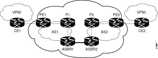
The network topology in the figure below shows a single internet service provider, which is partitioning the backbone with confederations. The autonomous system number of the provider is 100. The two autonomous systems run their own IGPs and are configured as follows:
- Autonomous system 1 (AS1) includes provider edge 1 (PE1), P1, Autonomous System Border Router 1 (ASBR1). The Interior Gateway Protocol (IGP) is Open Shortest Path First (OSPF).
- Autonomous system 2 (AS2) includes PE2, P2, ASBR2. The IGP is Intermediate System to Intermediate System (IS-IS).
- Customer edge 1 (CE1) and CE2 belong to the same VPN, which is called VPN1.
- The P devices are route reflectors.
- ASBR1 is configured with the redistribute connected subnets command.
- ASBR2 is configured with the neighbor next-hop-selfcommand.
- Example: Configuration for Autonomous System 1 CE1
- Example: Configuration for Autonomous System 1 PE1
- Example: Configuration for Autonomous System 1 P1
- Example: Configuration for Autonomous System 1 ASBR1
- Example: Configuration for Autonomous System 2 ASBR2
- Example: Configuration for Autonomous System 2 P2
- Example: Configuration for Autonomous System 2 PE2
- Example: Configuration for Autonomous System 2 CE2
Example: Configuration for Autonomous System 1 CE1
The following example shows how to configure CE1 in VPN1 in a confederation topology:
interface Loopback1
 ip address 192.168.3.4 255.255.255.255
!
interface GigabitEthernet0/4/7
 no ip address
 encapsulation frame-relay
 frame-relay intf-type dce
!
interface GigabitEthernet0/4/7.1 point-to-point
 ip address 192.168.1.3 255.255.0.0
 frame-relay interface-dlci 22
!
router ospf 1
 network 192.168.0.1 255.255.0.0 area 0
Example: Configuration for Autonomous System 1 PE1
The following example shows how to configure PE1 in AS1 in a confederation topology:
ip cef
!
ip vrf V1
 rd 1:105
 route-target export 1:100
 route-target import 1:100
!
interface GigabitEthernet0/0/0
 no ip address
 encapsulation frame-relay
 no fair-queue
 clockrate 2000000
!
interface GigabitEthernet0/0/0.3 point-to-point
 ip vrf forwarding V1
 ip address 10.0.2.4 255.0.0.0
 frame-relay interface-dlci 22
!
interface GigabitEthernet0/4/7
 ip address 10.1.2.6 255.0.0.0
 tag-switching ip
!
router ospf 1
 log-adjacency-changes
 network 10.1.8.4 255.0.0.0 area 0
!
router ospf 10 vrf V1
 log-adjacency-changes
 redistribute bgp 1 metric 100 subnets
 network 10.1.8.4 255.0.0.0 area 0
!
router bgp 1
 no synchronization
 bgp confederation identifier 100
 bgp confederation identifier 100
 neighbor 1 peer-group
 neighbor 1 remote-as 1
 neighbor 1 update-source Loopback0
 neighbor 10.2.1.2 peer-group R
 no auto-summary
 !
 address-family ipv4 vrf V1
  redistribute ospf 10
  no auto-summary
  no synchronization
  exit-address-family
 !
 address-family vpnv4
  neighbor R activate
  neighbor R send-community extended
  neighbor 10.2.1.2 peer-group R
  no auto-summary
  exit-address-family
Example: Configuration for Autonomous System 1 P1
The following example shows how to configure P1 in AS1 in a confederation topology:
ip cef
!
interface Loopback0
 ip address 10.0.0.2 255.0.0.0
!
interface GigabitEthernet0/0/0
 ip address 10.2.1.1 255.0.0.0
 tag-switching ip
!
interface GigabitEthernet0/4/7
 ip address 10.2.2.1 255.0.0.0
 duplex auto
 speed auto
 tag-switching ip
!
router ospf 1
 log-adjacency-changes
 network 10.1.2.2 255.0.0.0 area 0
!
router bgp 1
 no synchronization
 bgp log-neighbor-changes
 bgp confederation identifier 100
 neighbor R peer-group
 neighbor R remote-as 1
 neighbor R update-source Loopback0
 neighbor R route-reflector-client
 neighbor 10.0.0.4 peer-group R
 neighbor 10.0.0.5 peer-group R
 !
 address-family vpnv4
  neighbor R activate
  neighbor R route-reflector-client
  neighbor R send-community extended
  neighbor 10.1.0.4 peer-group R
  neighbor 10.1.0.5 peer-group R
  exit-address-family
Example: Configuration for Autonomous System 1 ASBR1
The following example shows how to configure ASBR1 in AS1 in a confederation topology:
ip cef
!
interface Loopback0
 ip address 10.0.0.4 255.0.0.0
!
interface GigabitEthernet0/0/0
 ip address 10.2.1.40 255.255.255.0
 tag-switching ip
!
interface GigabitEthernet0/5/3
 no ip address
 no atm scrambling cell-payload
 no atm ilmi-keepalive
!
interface GigabitEthernet0/5/3.1 point-to-point
 ip address 10.0.0.1 255.0.0.0
 pvc 1/100
!
router ospf 1
 log-adjacency-changes
 redistribute connected subnets
 network 10.0.0.3 255.0.0.0 area 0
!
router bgp 1
 no synchronization
 no bgp default route-target filter
 bgp log-neighbor-changes
 bgp confederation identifier 100
 bgp confederation peers 1
 neighbor R peer-group
 neighbor R remote-as 1
 neighbor R update-source Loopback0
 neighbor 10.0.0.2 remote-as 2
 neighbor 10.0.0.2 next-hop-self
 neighbor 10.0.0.2 peer-group R
 no auto-summary
 !
 address-family vpnv4
  neighbor R activate
  neighbor R send-community extended
  neighbor 10.0.0.2 activate
  neighbor 10.0.0.2 next-hop-self
  neighbor 10.0.0.2 send-community extended
  neighbor 10.0.0.2 peer-group R
  no auto-summary
  exit-address-family
Example: Configuration for Autonomous System 2 ASBR2
The following example shows how to configure ASBR2 in AS2 in a confederation topology:
ip cef
!
ip vrf V1
 rd 2:103
 route-target export 1:100
 route-target import 1:100
!
interface Loopback0
 ip address 10.0.0.3 255.0.0.0
 ip router isis
!
interface Loopback1
 ip vrf forwarding V1
 ip address 10.0.0.3 255.0.0.0
!
interface GigabitEthernet0/4/7
 no ip address
 encapsulation frame-relay
 load-interval 30
 no fair-queue
 clockrate 2000000
!
interface GigabitEthernet0/4/7.2 point-to-point
 ip unnumbered Loopback0
 ip router isis
 tag-switching ip
 frame-relay interface-dlci 23
!
interface GigabitEthernet0/5/3
 no ip address
 atm clock INTERNAL
 no atm scrambling cell-payload
 no atm ilmi-keepalive
!
interface GigabitEthernet0/5/3.1 point-to-point
 ip address 10.0.0.2 255.0.0.0
 pvc 1/100
!
router isis
 net aa.0002.0000.0000.0003.00
!
router bgp 2
 no synchronization
 no bgp default route-target filter
 bgp log-neighbor-changes
 bgp confederation identifier 100
 bgp confederation peers 1
 neighbor 10.0.0.1 remote-as 1
 neighbor 10.0.0.1 next-hop-self
 neighbor 10.0.0.8 remote-as 2
 neighbor 10.0.0.8 update-source Loopback0
 neighbor 10.0.0.8 next-hop-self
 !
 address-family ipv4 vrf V1
  redistribute connected
  no auto-summary
  no synchronization
  exit-address-family
 !
 address-family vpnv4
  neighbor 10.0.0.1 activate
  neighbor 10.0.0.1 next-hop-self
  neighbor 10.0.0.1 send-community extended
  neighbor 10.0.0.8 activate
  neighbor 10.0.0.8 next-hop-self
  neighbor 10.0.0.8 send-community extended
  exit-address-family
Example: Configuration for Autonomous System 2 P2
The following example shows how to configure P2 in AS2 in a confederation topology:
ip cef
!
ip vrf V1
 rd 2:108
 route-target export 1:100
 route-target import 1:100
!
interface Loopback0
 ip address 10.0.0.8 255.0.0.0
 ip router isis
!
interface Loopback1
 ip vrf forwarding V1
 ip address 10.0.0.8 255.0.0.0
!
interface GigabitEthernet0/0/0
 ip address 10.9.1.2 255.0.0.0
 ip router isis
 tag-switching ip
!
interface GigabitEthernet0/5/3
 no ip address
 encapsulation frame-relay
 frame-relay intf-type dce
!
interface GigabitEthernet0/5/3.1 point-to-point
 ip unnumbered Loopback0
 ip router isis
 tag-switching ip
 frame-relay interface-dlci 23
!
router isis
 net aa.0002.0000.0000.0008.00
!
router bgp 2
 no synchronization
 bgp log-neighbor-changes
 bgp confederation identifier 100
 neighbor R peer-group
 neighbor R remote-as 2
 neighbor R update-source Loopback0
 neighbor R route-reflector-client
 neighbor 10.0.0.3 peer-group R
 neighbor 10.0.0.9 peer-group R
 !
 address-family ipv4 vrf V1
  redistribute connected
  no auto-summary
  no synchronization
  exit-address-family
 !
 address-family vpnv4
  neighbor R activate
  neighbor R route-reflector-client
  neighbor R send-community extended
  neighbor 10.0.0.3 peer-group R
  neighbor 10.0.0.9 peer-group R
  exit-address-family
Example: Configuration for Autonomous System 2 PE2
The following example shows how to configure PE2 in AS2 in a confederation topology:
ip cef
!
ip vrf V1
 rd 2:109
 route-target export 1:100
 route-target import 1:100
!
interface Loopback0
 ip address 10.0.0.9 255.0.0.0
 ip router isis
!
interface Loopback1
 ip vrf forwarding V1
 ip address 10.0.0.9 255.0.0.0
!
interface GigabitEthernet0/0/4
 no ip address
 encapsulation frame-relay
 frame-relay intf-type dce
 no fair-queue
 clockrate 2000000
!
interface GigabitEthernet0/0/4.1 point-to-point
 description Bethel
 ip vrf forwarding V1
 ip unnumbered Loopback1
 frame-relay interface-dlci 24
!
interface GigabitEthernet0/4/7
 ip address 10.9.1.1 255.0.0.0
 ip router isis
 tag-switching ip
!
router ospf 10 vrf V1
 log-adjacency-changes
 redistribute bgp 2 subnets
 network 10.0.0.2 255.0.0.0 area 0
!
router isis
 net aa.0002.0000.0000.0009.00
!
router bgp 2
 no synchronization
 bgp log-neighbor-changes
 bgp confederation identifier 100
 neighbor 10.0.0.8 remote-as 2
 neighbor 10.0.0.8 update-source Loopback0
 !
 address-family ipv4 vrf V1
  redistribute connected
  redistribute ospf 10
  no auto-summary
  no synchronization
  exit-address-family
 !
 address-family vpnv4
  neighbor 10.0.0.8 activate
  neighbor 10.0.0.8 send-community extended
  exit-address-family
Example: Configuration for Autonomous System 2 CE2
The following example shows how to configure CE2 in VPN1 in a confederation topology:
interface Loopback0
 ip address 10.0.0.11 255.0.0.0
!
interface GigabitEthernet0/0/7
 no ip address
 encapsulation frame-relay
 no fair-queue
 clockrate 2000000
!
interface GigabitEthernet0/0/7.1 point-to-point
ip unnumbered Loopback0
 frame-relay interface-dlci 24
!
router ospf 1
 network 10.0.1.2 255.0.0.0 area 0
Additional References
Related Documents
|
Related Topic |
Document Title |
|---|---|
|
MPLS |
Standards
|
Standard |
Title |
|---|---|
|
No new or modified standards are supported by this feature, and support for existing standards has not been modified by this feature. |
-- |
MIBs
|
MIB |
MIBs Link |
|---|---|
|
No new or modified MIBs are supported by this feature, and support for existing MIBs has not been modified by this feature. |
To locate and download MIBs for selected platforms, Cisco software releases, and feature sets, use Cisco MIB Locator found at the following URL: |
RFCs
|
RFC |
Title |
|---|---|
|
RFC 1700 |
Assigned Numbers |
|
RFC 1966 |
BGP Route Reflection: An Alternative to Full Mesh IBGP |
|
RFC 2842 |
Capabilities Advertisement with BGP-4 |
|
RFC 2858 |
Multiprotocol Extensions for BGP-4 |
|
RFC 3107 |
Carrying Label Information in BGP-4 |
Technical Assistance
|
Description |
Link |
|---|---|
|
The Cisco Support website provides extensive online resources, including documentation and tools for troubleshooting and resolving technical issues with Cisco products and technologies. To receive security and technical information about your products, you can subscribe to various services, such as the Product Alert Tool (accessed from Field Notices), the Cisco Technical Services Newsletter, and Really Simple Syndication (RSS) Feeds. Access to most tools on the Cisco Support website requires a Cisco.com user ID and password. |
Feature Information for MPLS VPN Inter-AS with ASBRs Exchanging VPN-IPv4 Addresses
The following table provides release information about the feature or features described in this module. This table lists only the software release that introduced support for a given feature in a given software release train. Unless noted otherwise, subsequent releases of that software release train also support that feature.
Use Cisco Feature Navigator to find information about platform support and Cisco software image support. To access Cisco Feature Navigator, go to www.cisco.com/go/cfn. An account on Cisco.com is not required.
|
Feature Name |
Releases |
Feature Information |
|---|---|---|
|
MPLS VPN Interautonomous System Support |
Cisco IOS XE Release 3.7S |
The MPLS VPN Interautonomous System Support feature enables an MPLS VPN to span service providers and autonomous systems. This feature explains how to configuring the Inter-AS using the ASBRs to exchange VPN-IPv4 Addresses. In Cisco IOS XE Release 3.7S, support was added for the Cisco ASR 903 Router. This feature uses no new or modified commands. |