- MPLS LSP Ping Traceroute for LDP TE and LSP Ping for VCCV
- MPLS EM MPLS LSP Multipath Tree Trace
- MPLS Enhancements to Interfaces MIB
- MPLS Label Switching Router MIB
- Pseudowire Emulation Edge-to-Edge MIBs
- MPLS Label Distribution Protocol MIB Version 8 Upgrade
- MPLS Traffic Engineering MIB
- MPLS Traffic Engineering Fast Reroute MIB
- Monitoring MPLS VPNs with MIBs
- MPLS VPN MIB Support
- Finding Feature Information
- Prerequisites for PPVPN MPLS VPN MIB
- Restrictions for PPVPN MPLS VPN MIB
- Information About PPVPN MPLS VPN MIB
- MIB Objects Not Supported
Monitoring MPLS VPNs with MIBs
This module explains how to use the PPVPN-MPLS-VPN management information base (MIB) to monitor and manage Multiprotocol Label Switching (MPLS) Virtual Private Networks. The following MIBs are supported:
Finding Feature Information
Your software release may not support all the features documented in this module. For the latest feature information and caveats, see the release notes for your platform and software release. To find information about the features documented in this module, and to see a list of the releases in which each feature is supported, see the Feature Information Table at the end of this document.
Use Cisco Feature Navigator to find information about platform support and Cisco software image support. To access Cisco Feature Navigator, go to www.cisco.com/go/cfn. An account on Cisco.com is not required.
Prerequisites for PPVPN MPLS VPN MIB
The PPVPN-MPLS-VPN MIB agent requires the following:
- SNMP is installed and enabled on the label switching routers.
- MPLS is enabled on the label switching routers.
- Multiprotocol Border Gateway Protocol (BGP) is enabled on the label switching routers.
- Cisco Express Forwarding is enabled on the label switching routers.
Restrictions for PPVPN MPLS VPN MIB
Information About PPVPN MPLS VPN MIB
- MPLS VPN Overview
- PPVPN MPLS VPN MIB Overview
- PPVPN MPLS VPN MIB and the IETF
- Capabilities Supported by PPVPN-MPLS-VPN MIB
- Functional Structure of the PPVPN-MPLS-VPN MIB
- Supported Objects in PPVPN-MPLS-VPN MIB
- MIB Objects Not Supported
MPLS VPN Overview
The MPLS VPN technology allows service providers to offer intranet and extranet VPN services that directly connect their customers' remote offices to a public network with the same security and service levels that a private network offers. Each VPN is associated with one or more VPN routing/forwarding instances (VRFs). A VRF is created for each VPN defined on a router and contains most of the information needed to manage and monitor MPLS VPNs: an IP routing table, a derived Cisco Express Forwarding (CEF) table, a set of interfaces that use this forwarding table, and a set of rules and routing protocol parameters that control the information that is included in the routing table.
PPVPN MPLS VPN MIB Overview
The Provider-Provisioned VPN (PPVPN)-MPLS-VPN MIB provides access to VRF information, as well as interfaces included in the VRF, and other configuration and monitoring information.
The PPVPN-MPLS-VPN MIB provides the following benefits:
- A standards-based SNMP interface for retrieving information about critical MPLS VPN events.
- VRF information to assist in the management and monitoring of MPLS VPNs.
- Information, in conjunction with the Interfaces MIB, about interfaces assigned to VRFs.
- Performance statistics for all VRFs on a router.
- The generation and queuing of notifications that call attention to major changes in the operational status of MPLS VPN enabled interfaces; the forwarding of notification messages to a designated network management system (NMS) for evaluation and action by network administrators.
- Advanced warning when VPN routing tables are approaching or exceed their capacity.
- Warnings about the reception of illegal labels on a VRF-enabled interface. Such receptions may indicate misconfiguration or an attempt to violate security.
This document also describes the CISCO-IETF-PPVPN-MPLS-VPN-MIB, which contains the cMplsNumVrfRouteMaxThreshCleared notification.
PPVPN MPLS VPN MIB and the IETF
SNMP agent code operating with the PPVPN-MPLS-VPN MIB enables a standardized, SNMP-based approach to managing MPLS VPNs in Cisco IOS software.
The PPVPN-MPLS-VPN MIB is based on the IETF draft MIB specification draft-ietf-ppvpn-mpls-vpn-mib-03.txt , which includes objects describing features that support MPLS VPN events. This IETF draft MIB, which undergoes revisions from time to time, is being evolved toward becoming a standard. Accordingly, the Cisco implementation of the PPVPN-MPLS-VPN MIB is expected to track the evolution of the IETF draft MIB, and may change accordingly.
Some slight differences between the IETF draft MIB and the actual implementation of MPLS VPNs within Cisco IOS software require some minor translations between the PPVPN-MPLS-VPN MIB and the internal data structures of Cisco IOS. These translations are accomplished by means of the SNMP agent code. Also, while running as a low priority process, the SNMP agent provides a management interface to Cisco IOS. SNMP adds little overhead on the normal functions of the device.
The SNMP objects defined in the PPVPN-MPLS-VPN MIB can be viewed by any standard SNMP utility. The network administrator can retrieve information in the PPVPN-MPLS-VPN MIB using standard SNMP get and getnext operations for SNMP v1, v2, and v3.
All PPVPN-MPLS-VPN MIB objects are based on the IETF draft MIB; thus, no Cisco specific SNMP application is required to support the functions and operations pertaining to the PPVPN-MPLS-VPN MIB features.
Capabilities Supported by PPVPN-MPLS-VPN MIB
The following functionality is supported by the PPVPN-MPLS-VPN MIB. The PPVPN-MPLS-VPN MIB provides you with the ability to do the following:
- Gather routing and forwarding information for MPLS VPNs on a router.
- Expose information in the VRF routing table.
- Gather information on BGP configuration related to VPNs and VRF interfaces and statistics.
- Emit notification messages that signal changes when critical MPLS VPN events occur.
- Enable, disable, and configure notification messages for MPLS VPN events by using extensions to existing SNMP CLI commands.
- Specify the IP address of a network management system (NMS) in the operating environment to which notification messages are sent.
- Write notification configurations into nonvolatile memory.
Functional Structure of the PPVPN-MPLS-VPN MIB
The SNMP agent code supporting the PPVPN-MPLS-VPN MIB follows the existing model for such code in Cisco IOS software and is, in part, generated by the Cisco tool set, based on the MIB source code.
The SNMP agent code, which has a layered structure that is common to MIB support code in Cisco software, consists of four layers:
- Platform-independent layer--This layer is generated primarily by the MIB development Cisco tool set and incorporates platform- and implementation-independent functions. The Cisco MIB development tool set creates a standard set of files associated with a MIB.
- Application interface layer--The functions, names, and template code for MIB objects in this layer are also generated by the MIB development Cisco tool set.
- Application-specific layer--This layer provides an interface between the application interface layer and the API and data structures layer below and performs tasks needed to retrieve required information from Cisco software, such as searching through data structures.
- API and data structures layer--This layer contains the data structures or APIs within Cisco software that are retrieved or called in order to set or retrieve SNMP management information.
Supported Objects in PPVPN-MPLS-VPN MIB
The PPVPN-MPLS-VPN MIB contains numerous tables and object definitions that provide read-only SNMP management support for the MPLS VPN feature in Cisco software. The PPVPN-MPLS-VPN MIB conforms to Abstract Syntax Notation One (ASN.1), thus reflecting an idealized MPLS VPN database.
Using any standard SNMP network management application, you can retrieve and display information from the PPVPN-MPLS-VPN MIB using GET operations; similarly, you can traverse information in the MIB database for display using GETNEXT operations.
The PPVPN-MPLS-VPN MIB tables and objects are described briefly in the following sections:
Objects that are not supported are listed in the MIB Objects Not Supported section.
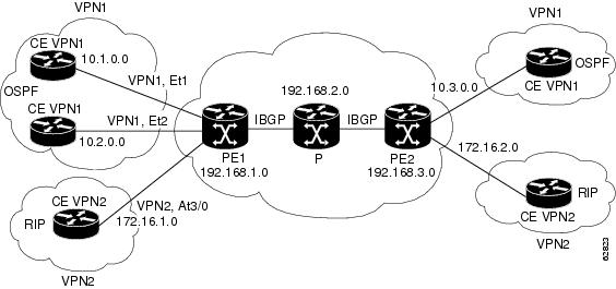
The figure below shows a simple MPLS VPN configuration. This configuration includes two customer MPLS VPNs, labeled VPN1 and VPN2, and a simple provider network that consists of two provider edge (PE) routers, labeled PE1 and PE2, and a provider core router labeled P. The figure shows the following sample configuration:
- VRF names--VPN1 and VPN2
- Interfaces associated with VRFs--Et1, Et2, and At3/0
- Routing protocols--OSPF, RIP, and IBGP
- Routes associated with VPN1--10.1.0.0, 10.2.0.0, and 10.3.0.0
- Routes associated with VPN2--172.16.1.0 and 172.16.2.0
- Routes associated with the provider network--192.168.1.0, 192.168.2.0, and 192.168.3.0
This configuration is used in this document to explain MPLS VPN events that are monitored and managed by the PPVPN-MPLS-VPN MIB.
| Figure 1 | Sample MPLS VPN Configuration |
Scalar Objects
The table below shows the supported PPVPN-MPLS-VPN MIB scalar objects.
| Table 1 | PPVPN-MPLS-VPN MIB Scalar Objects |
MIB Tables
The PPVPN-MPLS-VPN MIB implementation supports the following tables described in this section:
- mplsVpnVrfTable
- mplsVpnInterfaceConfTable
- mplsVpnVrfRouteTargetTable
- mplsVpnVrfBgpNbrAddrTable
- mplsVpnVrfSecTable
- mplsVpnVrfPerfTable
- mplsVpnVrfRouteTable
mplsVpnVrfTable
Entries in the VRF configuration table (mplsVpnVrfTable) represent the VRFs that are defined on the router. This includes recently deleted VRFs. The information in this table is also displayed with the show ip vrf command.
Each VRF is referenced by its VRF name (mplsVpnVrfName).
The table below lists the MIB objects and their functions for this table.
| Table 2 | PPVPN-MPLS-VPN MIB Objects for the mplsVpnVrfTable |
mplsVpnInterfaceConfTable
In Cisco software, a VRF is associated with one MPLS VPN. Zero or more interfaces can be associated with a VRF. A VRF uses an interface that is defined in the ifTable of the Interfaces Group of MIB II (IFMIB). The IFMIB defines objects for managing interfaces. The ifTable of this MIB contains information on each interface in the network. The mplsVpnInterfaceConfTable associates a VRF from the mplsVpnVrfTable with a forwarding interface from the ifTable. The figure below shows the relationship between VRFs and interfaces defined in the ifTable and the mplsVpnInterfaceConfTable.
| Figure 2 | VRFs, the Interfaces MIB, and the mplsVpnInterfaceConfTable |
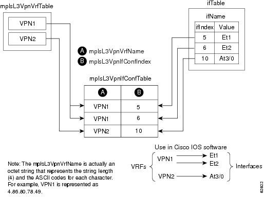
Entries in the VPN interface configuration table (mplsVpnInterfaceConfTable) represent the interfaces that are assigned to each VRF. The information available in this table is also displayed with the show ip vrf command.
The mplsVpnInterfaceConfTable shows how interfaces are assigned to VRFs. A label switch router (LSR) creates an entry in this table for every interface capable of supporting MPLS VPNs.
The mplsVpnInterfaceConfTable is indexed by the following:
- mplsVpnVrfName--The VRF name
- mplsVpnInterfaceConfIndex--An identifier that is the same as the ifIndex from the Interface MIB of the interface assigned to the VRF
The table below lists the MIB objects and their functions for this table.
| Table 3 | PPVPN-MPLS-VPN MIB Objects for the mplsVpnInterfaceConfTable |
| MIB Object |
Function |
|---|---|
| mplsVpnInterfaceConfIndex |
Provides the interface MIB ifIndex of this interface that is assigned to a VRF. |
| mplsVpnInterfaceLabelEdgeType |
Indicates whether the interface is a provider edge interface (1) or a customer edge interface (2). This value is always providerEdge (1) because in Cisco IOS, customerEdge interfaces are not assigned to VRFs and do not appear in this table. |
| mplsVpnInterfaceVpnClassification |
Specifies what type of VPN this interface is providing: carrier supporting carrier (CsC) (1), enterprise (2), or InterProvider (3). This value is set to enterprise (2) if MPLS is not enabled and to carrier supporting carrier (1) if MPLS is enabled on this interface. |
| mplsVpnInterfaceVpnRouteDistProtocol |
Indicates the route distribution protocols that are being used to redistribute routes with BGP on this interface: BGP (2), OSPF (3), or RIP (4). In Cisco software, router processes are defined and redistributed on a per-VRF basis, not per-interface. Therefore, all interfaces assigned to the same VRF have the same value for this object. |
| mplsVpnInterfaceConfStorageType |
Read-only implementation. This object always reads "volatile (2)." |
| mplsVpnInterfaceConfRowStatus |
Read-only implementation. This object normally reads "active (1)," but may read "notInService (2)," if a VRF was recently deleted. |
mplsVpnVrfRouteTargetTable
The route target table (mplsVpnVrfRouteTargetTable) describes the route target communities that are defined for a particular VRF. An LSR creates an entry in this table for each target configured for a VRF supporting an MPLS VPN instance.
The distribution of VPN routing information is controlled through the use of VPN route target communities, implemented by Border Gateway Protocol (BGP) extended communities. Distribution of VPN routing information works as follows:
- When a VPN route learned from a CE router is injected into BGP, a list of VPN route target extended community attributes are associated with it. Typically the list of route target community values is set from an export list of route targets associated with the VRF from which the route was learned.
- An import list of route target extended communities is associated with each VRF. The import list defines route target extended community attributes a route must have for the route to be imported into the VRF. For example, if the import list for a particular VRF includes route target communities A, B, and C, then any VPN route that carries any of those route target extended communities--A, B, or C--is imported into the VRF.
The figure below shows a sample configuration and its relationship to an mplsVpnVrfRouteTargetTable. A route target table exists on each PE router. Routers with route distinguishers (RDs) 100:1, 100:2, and 100:3 are shown in the sample configuration. Routers with RDs 100:4 and 100:5 are not shown in the figure, but are included in the route targets for PE2 and in the mplsVpnVrfRouteTargetTable.
| Figure 3 | Sample Configuration and the mplsVpnVrfRouteTargetTable |
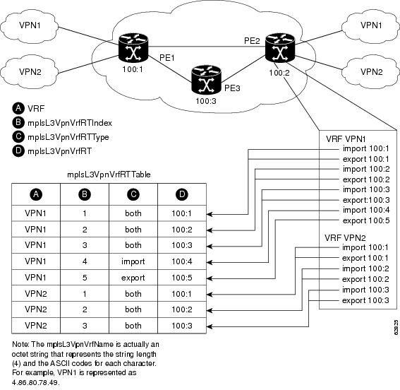
The mplsVpnVrfRouteTargetTable shows the import and export route targets for each VRF. The table is indexed by the following:
- mplsVpnVrfName--The VRF name
- mplsVpnVrfRouteTargetIndex--The route target entry identifier
- mplsVpnVrfRouteTargetType--A value specifying whether the entry is an import route target, export route target, or is defined as both
The table below lists the MIB objects and their functions for this table.
| Table 4 | PPVPN-MPLS-VPN MIB Objects for the mplsVpnVrfRouteTargetTable |
| MIB Object |
Function |
|---|---|
| mplsVpnVrfRouteTargetIndex |
A value that defines each route target's position in the table. |
| mplsVpnVrfRouteTargetType |
Determines which type of route target the entry represents: import (1), export (2), or both (3). |
| mplsVpnVrfRouteTarget |
Determines the route distinguisher for this target. |
| mplsVpnVrfRouteTargetDescr |
Description of the route target. This object is not supported. Therefore, the object is the same as mplsVpnVrfRouteTarget. |
| mplsVpnVrfRouteTargetRowStatus |
Read-only implementation. This object normally reads "active (1)," but may read "notInService (2)," if a VRF was recently deleted. |
mplsVpnVrfBgpNbrAddrTable
The BGP neighbor address table (mplsVpnVrfBgpNbrAddrTable) represents the MPLS eBGP neighbors that are defined for a particular VRF. An LSR creates an entry for every BGP neighbor that is defined in the VRF's address-family.
The mplsVpnVrfBgpNbrAddrTable is indexed by the following:
- mplsVpnVrfName--The VRF name
- mplsVpnInterfaceConfIndex--An identifier that is the same as the ifIndex from the Interface MIB of the interface assigned to the VRF
- mplsVpnVrfBgpNbrIndex--The IP address of the neighbor
The table below lists the MIB objects and their functions for this table.
| Table 5 | PPVPN-MPLS-VPN MIB Objects for the mplsVpnVrfBgpNbrAddrTable |
| MIB Object |
Function |
|---|---|
| mplsVpnVrfBgpNbrIndex |
The IPv4 address of the eBGP neighbor. |
| mplsVpnVrfBgpNbrRole |
The role of this eBGP neighbor: customer edge (1) or provider edge (2). If the object mplsVpnInterfaceVpnClassification is carrier supporting carrier (CSC), then this value is provider edge (2), otherwise, this value is customer edge (1). |
| mplsVpnVrfBgpNbrType |
Address type of this eBGP neighbor. The MIB only supports IPv4 (1). Therefore, this object returns "ipv4 (1)." |
| mplsVpnVrfBgpNbrAddr |
IP address of the eBGP neighbor. |
| mplsVpnVrfBgpNbrRowStatus |
Read-only implementation. This object normally reads "active (1)," but may read "notInService (2)" if a VRF was recently deleted. |
| mplsVpnVrfBgpNbrStorageType |
Read-only implementation. This object always reads "volatile (2)." |
mplsVpnVrfSecTable
The VRF security table (mplsVpnVrfSecTable) provides information about security for each VRF. An LSR creates an entry in this table for every VRF capable of supporting MPLS VPN.
The mplsVpnVrfSecTable augmentsthe mplsVpnVrfTable and has the same indexing.
The table below lists the MIB objects and their functions for this table.
| Table 6 | PPVPN-MPLS-VPN MIB Objects for the mplsVpnVrfSecTable |
| MIB Object |
Function |
|---|---|
| mplsVpnVrfSecIllegalLabelViolations |
The number of illegally received labels on a VRF interface. Only illegal labels are counted by this object, therefore the object only applies to a VRF interface that is MPLS enabled (carrier supporting carrier [CsC] situation). This counter is incremented whenever a label is received that is above or below the valid label range, not in the global label forwarding table, or is received on the wrong VRF (that is, table IDs for the receiving interface and appropriate VRF label forwarding table do not match). |
| mplsVpnVrfSecIllegalLabelRcvThresh |
Notification threshold for illegal labels received on this VRF. When the amount of illegal labels received on this interface crosses this threshold, an mplsNumVrfSecIllegalLabelThreshExceeded notification is sent (if the notification is enabled and configured). This object is one of the few in this MIB agent that supports the SNMP SET operation, which allows you to change this value. |
mplsVpnVrfPerfTable
The VRF performance table (mplsVpnVrfPerfTable) provides statistical performance information for each VRF. An LSR creates an entry in this table for every VRF capable of supporting MPLS VPN.
The mplsVpnVrfPerfTable augments the mplsVpnVrfTable and has the same indexing.
The table below lists the MIB objects and their functions for this table.
| Table 7 | PPVPN-MPLS-VPN MIB Objects for the mplsVpnVrfPerfTable |
| MIB Objects |
Functions |
|---|---|
| mplsVpnVrfPerfRoutesAdded |
The number of routes added to this VRF over the course of its lifetime. |
| mplsVpnVrfPerfRoutesDeleted |
The number of routes removed from this VRF. |
| mplsVpnVrfPerfCurrNumRoutes |
The number of routes currently defined within this VRF. |
mplsVpnVrfRouteTable
The VRF routing table (mplsVpnVrfRouteTable) provides the IP routing table information for each VRF. The information available in this table can also be accessed with the show ip route vrf vrf-name command. For example, for PE1 in the figure above:
Router# show ip route vrf vpn1
Codes: C - connected, S - static, I - IGRP, R - RIP, M - mobile, B - BGP
D - EIGRP, EX - EIGRP external, O - OSPF, IA - OSPF inter area
N1 - OSPF NSSA external type 1, N2 - OSPF NSSA external type 2
E1 - OSPF external type 1, E2 - OSPF external type 2, E - EGP
i - IS-IS, L1 - IS-IS level-1, L2 - IS-IS level-2, ia - IS-IS inter area
* - candidate default, U - per-user static route, o - ODR
P - periodic downloaded static route
!
Gateway of last resort is not set
!
     10.0.0.0/32 is subnetted, 3 subnets
B       10.3.0.0 [200/0] via 192.168.2.1, 04:36:33
C       10.1.0.0/16 is directly connected, Ethernet1
C       10.2.0.0/16 [200/0] directly connected Ethernet2, 04:36:33
Router# show ip route vrf vpn2
Codes: C - connected, S - static, I - IGRP, R - RIP, M - mobile, B - BGP
D - EIGRP, EX - EIGRP external, O - OSPF, IA - OSPF inter area
N1 - OSPF NSSA external type 1, N2 - OSPF NSSA external type 2
E1 - OSPF external type 1, E2 - OSPF external type 2, E - EGP
i - IS-IS, L1 - IS-IS level-1, L2 - IS-IS level-2, ia - IS-IS inter area
* - candidate default, U - per-user static route, o - ODR
P - periodic downloaded static route
!
Gateway of last resort is not set
!
     172.16.0.0/32 is subnetted, 2 subnets
B       172.16.2.0 [200/0] via 192.168.2.1, 04:36:33
C       172.16.1.0 is directly connected, ATM 3/0
The figure below shows the relationship of the routing tables, the VRFs, and the mplsVpnVrfRouteTable. You can view information about the VPN1 and VPN2 route tables using the show ip route vrf vrf-name command. The global route table is the same as ipCidrRouteTable in the IP-FORWARD-MIB. You can view information about the global route table with the show ip route command.
| Figure 4 | Route Table, VRFs, and the mplsVpnVrfRouteTable |
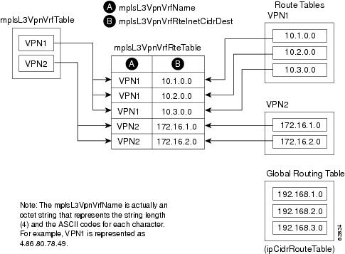
An LSR creates an entry in this table for every route that is configured, either dynamically or statically, within the context of a specific VRF capable of supporting MPLS VPN.
The mplsVpnVrfRouteTable is indexed by the following:
- mplsVpnVrfName--The VRF name, which provides the VRF routing context
- mplsVpnVrfRouteDest--The IP destination address
- mplsVpnVrfRouteMask--The IP destination mask
- mplsVpnVrfRouteTos--The IP header ToS bits
- mplsVpnVrfRouteNextHop--The IP address of the next hop for each route entry
 Note |
The ToS bits are not supported and, therefore, are always 0. |
The table below lists the MIB objects and their functions for the mplsVpnVrfRouteTable. This table represents VRF-specific routes. The global routing table is the ipCidrRouteTable in the IP-FORWARD-MIB.
| Table 8 | PPVPN-MPLS-VPN MIB Objects for the mplsVpnVrfRouteTable |
| MIB Object |
Function |
|---|---|
| mplsVpnVrfRouteDest |
The destination IP address defined for this route. |
| mplsVpnVrfRouteDestAddrType |
The address type of the IP destination address (mplsVpnVrfRouteDest). This MIB implementation only supports IPv4 (1). Therefore, this object has a value of "ipv4 (1)." |
| mplsVpnVrfRouteMask |
The destination IP address mask defined for this route. |
| mplsVpnVrfRouteMaskAddrType |
The address type of the destination IP address mask. This MIB implementation only supports IPv4 (1). Therefore, this object has a value of "ipv4 (1)." |
| mplsVpnVrfRouteTos |
The ToS bits from the IP header for this route. Cisco software only supports ToS bits of zero. Therefore, the object is always 0. |
| mplsVpnVrfRouteNextHop |
The next hop IP address defined for this route. |
| mplsVpnVrfRouteNextHopAddrType |
The address type of the next hop IP address. This MIB implementation only supports IPv4 (1). Therefore, this object has a value of "ipv4 (1)." |
| mplsVpnVrfRouteIfIndex |
The interface MIB ifIndex for the interface through which this route is forwarded. The object is 0 if no interface is defined for the route. |
| mplsVpnVrfRouteType |
Defines if this route is a local or remotely defined route. |
| mplsVpnVrfRouteProto |
The routing protocol that was responsible for adding this route to the VRF. |
| mplsVpnVrfRouteAge |
The number of seconds since this route was last updated. |
| mplsVpnVrfRouteInfo |
A pointer to more information from other MIBs. This object is not supported and always returns "nullOID (0.0)." |
| mplsVpnVrfRouteNextHopAS |
The autonomous system number of the next hop for this route. This object is not supported and is always 0. |
| mplsVpnVrfRouteMetric1 |
The primary routing metric used for this route. |
| mplsVpnVrfRouteMetric2 mplsVpnVrfRouteMetric3 mplsVpnVrfRouteMetric4 mplsVpnVrfRouteMetric5 |
Alternate routing metrics used for this route. These objects are supported only for Cisco IGRP and Cisco EIGRP. These objects display the bandwidth metrics used for the route. Otherwise, these values are set to -1. |
| mplsVpnVrfRouteRowStatus |
Read-only implementation.This object normally reads "active (1)," but may read "notInService (2)," if a VRF was recently deleted. |
| mplsVpnVrfRouteStorageType |
Read-only implementation. This object always reads "volatile (2)." |
Notifications
This section provides the following information about supported PPVPN-MPLS-VPN MIB notifications:
- PPVPN-MPLS-VPN MIB Notification Events
- CISCO-IETF-PPVPN-MPLS-VPN MIB Notification Events
- Notification Specification
- Monitoring the PPVPN-MPLS-VPN MIB Notifications
PPVPN-MPLS-VPN MIB Notification Events
The following notifications of the PPVPN-MPLS-VPN MIB are supported:
- mplsVrfIfUp --Sent to an NMS when an interface comes up and is assigned a VPN routing/forwarding table instance (VRF).
- mplsVrfIfDown --Generated and sent to the NMS when a VRF is removed from an interface or the interface transitions from an operationally "up" state to a "down" state.
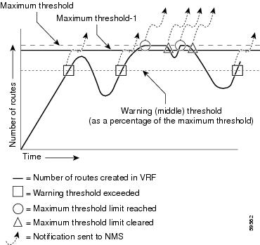
- mplsNumVrfRouteMidThreshExceeded --Generated and sent when the middle (warning) threshold is crossed. You can configure this threshold in the CLI by using the following commands:
Router(config)# ip vrf
vrf-name
Router(config-vrf)# maximum routes
limit warn-threshold
(
% of max
)
The warn-threshold argument is a percentage of the maximum routes specified by the limit argument. You can also configure a middle threshold with the following command, in which the limit argument represents the warning threshold:
Router(config-vrf)# maximum routes
limit
 warn-only
This notification is sent to the NMS only at the time the threshold is exceeded. (See the figure below for a comparison of the warning and maximum thresholds.) Whenever the number of routes falls below this threshold and exceeds the threshold again, a notification is sent to the NMS.
- mplsNumVrfRouteMaxThreshExceeded --Generated and sent when you attempt to create a route on a VRF that already contains the maximum number of routes as defined by the limit argument of the maximum routescommands:
Router(config)# ip vrf
 vrf-name
Router(config-vrf)# maximum routes
limit
warn-threshold (% of max)
A trap notification is sent to the NMS when you attempt to exceed the maximum threshold. Another mplsNumVrfRouteMaxThreshExceedednotification is not sent until the number of routes falls below the maximum threshold and reaches the maximum threshold again. (See the figure below for an example of how this notification works and for a comparison of the maximum and warning thresholds.)
Note |
The maximum routes command sets the number of routes for a VRF. You cannot exceed the number of routes in the VRF that you set with the maximum routes limit warn-thresholdcommand. Prior to this implementation of the PPVPN-MPLS-VPN MIB, you were not notified when this threshold (or the warning threshold) was reached. |
- mplsNumVrfSecIllegalLabelThreshExceeded --Generated and sent when the amount of illegal labels received on a VRF interface exceeds the threshold mplsVpnVrfSecIllegalLabelRcvThresh . This threshold is defined with a value of 0. Therefore, a notification is sent when the first illegal label is received on a VRF. Labels are considered illegal if they are outside of the valid label range, do not have a Label Forwarding Information Base (LFIB) entry, or the table ID of the message does not match the table ID for the label in the LFIB.
CISCO-IETF-PPVPN-MPLS-VPN MIB Notification Events
The following notification of the CISCO-IETF-PPVPN-MPLS-VPN MIB is supported in Cisco IOS Release 12.0(30)S:
- cMplsNumVrfRouteMaxThreshCleared--Generated and sent when the number of routes on a VRF attempts to exceed the maximum number of routes and then drops below the maximum number of routes. If youattempt to create a route on a VRF that already contains the maximum number of routes, the mplsNumVrfRouteMaxThreshExceeded notification is sent (if enabled). When you remove routes from the VRF so that the number of routes falls below the set limit, the cMplsNumVrfRouteMaxThreshCleared notification is sent. You can clear all routes from the VRF by using the clear ip route vrf command. (See the figure below to see when the cMplsNumVrfRouteMaxThreshCleared notification is sent.)
| Figure 5 | Comparison of Warning and Maximum Thresholds |
Notification Specification
In an SNMPv1 notification, each VPN notification has a generic type identifier and an enterprise-specific type identifier for identifying the notification type.
- The generic type for all VPN notifications is "enterpriseSpecific" as this is not one of the generic notification types defined for SNMP.
- The enterprise-specific type is identified as follows:
- 1 for mplsVrfIfUp
- 2 for mplsVrfIfDown
- 3 for mplsNumVrfRouteMidThreshExceeded
- 4 for mplsNumVrfRouteMaxThreshExceeded
- 5 for mplsNumVrfSecIllegalLabelThreshExceeded
- 6 for cMplsNumVrfRouteMaxThreshCleared
In SNMPv2, the notification type is identified by an SnmpTrapOID varbind (variable binding consisting of an object identifier [OID] type and value) included within the notification message.
Each notification also contains two additional objects from the PPVPN-MPLS-VPN MIB. These objects provide additional information about the event, as follows:
- The VRF interface up/down notifications provide additional variables--mplsVpnInterfaceConfIndex and mplsVpnVrfName-- in the notification. These variables describe the SNMP interface index and the VRF name, respectively.
- The mid and max threshold notifications include the mplsVpnVrfName variable (VRF name) as well as the mplsVpnVrfPerfCurrNumRoutes variable that indicates the current number of routes within the VRF.
- The illegal label notification includes the mplsVpnVrfName variable (VRF name) and the mplsVpnVrfSecIllegalLabelViolations variable that maintains the current count of illegal labels on a VPN.
Monitoring the PPVPN-MPLS-VPN MIB Notifications
When PPVPN-MPLS-VPN MIB notifications are enabled (see the snmp-server enable traps mpls vpn command), notification messages relating to specific MPLS VPN events within Cisco software are generated and sent to a specified NMS in the network. Any utility that supports SNMPv1 or SNMPv2 notifications can receive notification messages.
To monitor PPVPN-MPLS-VPN MIB notification messages, log in to an NMS that supports a utility that displays SNMP notifications, and start the display utility.
MIB Objects Not Supported
The following objects from the mplsVpnVrfBgpPathAttrTable are not supported:
- mplsVpnVrfBgpPathAttrPeer
- mplsVpnVrfBgpPathAttrIpAddrPrefixLen
- mplsVpnVrfBgpPathAttrIpAddrPrefix
- mplsVpnVrfBgpPathAttrOrigin
- mplsVpnVrfBgpPathAttrASPathSegment
- mplsVpnVrfBgpPathAttrNextHop
- mplsVpnVrfBgpPathAttrMultiExitDisc
- mplsVpnVrfBgpPathAttrLocalPref
- mplsVpnVrfBgpPathAttrAtomicAggregate
- mplsVpnVrfBgpPathAttrAggregatorAS
- mplsVpnVrfBgpPathAttrAggregatorAddr
- mplsVpnVrfBgpPathAttrCalcLocalPref
- mplsVpnVrfBgpPathAttrBest
- mplsVpnVrfBgpPathAttrUnknown
How to Configure PPVPN MPLS VPN MIB
- Configuring the SNMP Community
- Configuring the Router to Send SNMP Traps
- Configuring Threshold Values for MPLS VPN--SNMP Notifications
Configuring the SNMP Community
An SNMP community string defines the relationship between the SNMP manager and the agent. The community string acts like a password to regulate access to the agent on the router.
Perform this task to configure an SNMP community.
DETAILED STEPS
| Command or Action | Purpose | |
|---|---|---|
|
|
Example: Router> enable |
Enables privileged EXEC mode. |
|
|
Example: Router# show running-config |
Displays the running configuration to determine if an SNMP agent is already running. |
|
|
Example: Router# configure terminal |
Enters global configuration mode. |
|
|
Example: Router(config)# snmp-server community comaccess ro |
Sets up the community access string to permit access to the SNMP protocol.
|
|
|
Example: Router(config)# do copy running-config startup-config |
Saves the modified configuration to nonvolatile memory (NVRAM) as the startup configuration file. |
|
|
Example: Router(config)# exit |
Returns to privileged EXEC mode. |
|
|
Example: Router# show-running config | include smnp-server |
(Optional) Displays the configuration information currently on the router, the configuration for a specific interface, or map-class information. |
Configuring the Router to Send SNMP Traps
Perform this task to configure the router to send traps to a host.
The snmp-server host command specifies which hosts receive traps. The snmp-server enable traps command globally enables the trap production mechanism for the specified traps.
For a host to receive a trap, an snmp-server host command must be configured for that host, and, generally, the trap must be enabled globally through the snmp-server enable traps command.
Note |
Although you can set the community-string argument using the snmp-server host command by itself, we recommend you define this string using the snmp-server community command before using the snmp-server host command. |
DETAILED STEPS
| Command or Action | Purpose | |
|---|---|---|
|
|
Example: Router> enable |
Enables privileged EXEC mode. |
|
|
Example: Router# configure terminal |
Enters global configuration mode. |
|
|
Example: Router(config)# snmp-server host 172.20.2.160 traps comaccess mpls-vpn |
Specifies the recipient of an SNMP notification operation.
|
|
|
Example: Router(config)# snmp-server enable traps mpls vpn vrf-up vrf-down |
Enables the router to send MPLS VPN specific SNMP notifications (traps and informs).
|
|
|
Example: Router(config)# end |
(Optional) Exits to privileged EXEC mode. |
Configuring Threshold Values for MPLS VPN--SNMP Notifications
Perform this task to configure the following threshold values for MPLS VPN--SNMP notifications:
- The mplsNumVrfRouteMidThreshExceedednotification event is generated and sent when the middle (warning) threshold is crossed. You can configure this threshold in the CLI by using the maximum routes command in VRF configuration mode. This notification is sent to the NMS only at the time the threshold is exceeded. Whenever the number of routes falls below this threshold and exceeds the threshold again, a notification is sent to the NMS.
- The mplsNumVrfRouteMaxThreshExceeded notification event is generated and sent when you attempt to create a route on a VRF that already contains the maximum number of routes as defined by the maximum routes command in VRF configuration mode. A trap notification is sent to the NMS when you attempt to exceed the maximum threshold. Another mplsNumVrfRouteMaxThreshExceedednotification is not sent until the number of routes falls below the maximum threshold and reaches the maximum threshold again.
See the figure above for an example of how this notification works and for a comparison of the maximum and warning thresholds.
Note |
The maximum routes command sets the number of routes for a VRF. You cannot exceed the number of routes in the VRF that you set with the maximum routes limit warn-threshold command. Prior to this implementation of the PPVPN-MPLS-VPN MIB, you were not notified when this threshold (or the warning threshold) was reached. |
DETAILED STEPS
| Command or Action | Purpose | |
|---|---|---|
|
|
Example: Router> enable |
Enables privileged EXEC mode. |
|
|
Example: Router# configure terminal |
Enters global configuration mode. |
|
|
Example: Router(config)# ip vrf vpn1 |
Configures a VRF routing table and enters VRF configuration mode. |
|
|
Example: Router(config-vrf)# maximum routes 10000 80 Example: or Example: Router(config-vrf)# maximum routes 10000 warn-only |
Limits the maximum number of routes in a VRF to prevent a PE router from importing too many routes.
|
|
|
Example: Router(config-vrf)# end |
(Optional) Exits to privileged EXEC mode. |
Configuration Examples for PPVPN MPLS VPN MIB
- Configuring the SNMP Community Examples
- Configuring the Router to Send SNMP Traps Example
- Configuring Threshold Values for MPLS VPN--SNMP Notifications Examples
Configuring the SNMP Community Examples
The following example shows enabling a simple SNMP community group. This configuration permits any SNMP client to access all PPVPN-MPLS-VPN MIB objects with read-only access using the community string comaccess.
Router# configure terminal
Router(config)# snmp-server community
 comaccess ro
Verify that the SNMP master agent is enabled for the PPVPN MPLS VPN MIB feature:
Router# show running-config | include snmp-server
Building configuration...
....
snmp-server community comaccess RO
....
Note |
If you do not see any "snmp-server" statements, SNMP is not enabled on the router. |
Configuring the Router to Send SNMP Traps Example
The following example shows you how to enable the router to send MPLS VPN notifications to host 172.20.2.160 using the comaccess community string if a VRF transitions from an up or down state.
Router# configure terminal
Router(config)# snmp-server host 172.20.2.160 traps comaccess mpls-vpn
Router(config)# snmp-server enable traps mpls vpn vrf-up vrf-down
Configuring Threshold Values for MPLS VPN--SNMP Notifications Examples
The following example shows how to set a maximum threshold of 10000 routes and a warning threshold that is 80 percent of the maximum threshold for a VRF named vpn1 on a router:
Router(config)# ip vrf vpn1
Router(config-vrf)# maximum routes 10000 80
The following example shows how to set a warning threshold of 10000 routes for a VRF named vpn2 on a router. An error message is generated; however, additional routes are still allowed because a maximum route threshold is not set with this command.
Router(config)# ip vrf vpn2
Router(config-vrf)# maximum routes 10000 warn-only
Additional References
Related Documents
| Related Topic |
Document Title |
|---|---|
| Basic MPLS VPNs |
Configuring MPLS Layer 3 VPNs |
| MPLS VPN Carrier Supporting Carrier |
|
| MPLS VPN InterAutonomous Systems |
MPLS VPN Inter-AS with ASBRs Exchanging IPv4 Routes and MPLS Labels MPLS VPN Inter-AS with ASBRs Exchanging VPN-IPv4 Addresses |
Standards
| Standard |
Title |
|---|---|
| draft-ietf-ppvpn-mpls-vpn-mib-03 |
MPLS/BGP Virtual Private Network Management Information Base Using SMIv2 |
MIBs
| MIB |
MIBs Link |
|---|---|
| To locate and download MIBs for selected platforms, Cisco software releases, and feature sets, use Cisco MIB Locator found at the following URL: |
RFCs
| RFC |
Title |
|---|---|
| RFC 2233 |
The Interfaces Group MIB using SMIv2 |
| RFC 2547bis |
BGP/MPLS VPNs |
Technical Assistance
| Description |
Link |
|---|---|
| The Cisco Technical Support website contains thousands of pages of searchable technical content, including links to products, technologies, solutions, technical tips, and tools. Registered Cisco.com users can log in from this page to access even more content. The Cisco Support website provides extensive online resources, including documentation and tools for troubleshooting and resolving technical issues with Cisco products and technologies. To receive security and technical information about your products, you can subscribe to various services, such as the Product Alert Tool (accessed from Field Notices), the Cisco Technical Services Newsletter, and Really Simple Syndication (RSS) Feeds. Access to most tools on the Cisco Support website requires a Cisco.com user ID and password. |
Feature Information for PPVPN MPLS VPN MIB
The following table provides release information about the feature or features described in this module. This table lists only the software release that introduced support for a given feature in a given software release train. Unless noted otherwise, subsequent releases of that software release train also support that feature.
Use Cisco Feature Navigator to find information about platform support and Cisco software image support. To access Cisco Feature Navigator, go to www.cisco.com/go/cfn. An account on Cisco.com is not required.
| Table 9 | Feature Information for Monitoring MPLS VPNs with MIBs |
| Feature Name |
Releases |
Feature Configuration Information |
|---|---|---|
| MPLS VPN--MIB Support |
12.0(21)ST 12.0(22)S 12.2(13)S 12.2(15)T 12.0(24)S1 12.0(25)S 12.0(30)S |
This feature allows you to monitor and manage MPLS VPNs using MIBs. |
Cisco and the Cisco logo are trademarks or registered trademarks of Cisco and/or its affiliates in the U.S. and other countries. To view a list of Cisco trademarks, go to this URL: www.cisco.com/go/trademarks. Third-party trademarks mentioned are the property of their respective owners. The use of the word partner does not imply a partnership relationship between Cisco and any other company. (1110R)
Any Internet Protocol (IP) addresses and phone numbers used in this document are not intended to be actual addresses and phone numbers. Any examples, command display output, network topology diagrams, and other figures included in the document are shown for illustrative purposes only. Any use of actual IP addresses or phone numbers in illustrative content is unintentional and coincidental.
 Feedback