Contents
- MPLS Transport Profile
- Finding Feature Information
- Restrictions for MPLS Transport Profile
- Information About MPLS-TP
- How MPLS Transport Profile Works
- MPLS-TP Path Protection
- Bidirectional LSPs
- Support for MPLS Transport Profile OAM
- MPLS Transport Profile Static and Dynamic Multisegment Pseudowires
- MPLS-TP OAM Status for Static and Dynamic Multisegment Pseudowires
- MPLS Transport Profile Links and Physical Interfaces
- Tunnel Midpoints
- MPLS-TP Linear Protection with PSC Support
- MPLS-TP Linear Protection with PSC Support Overview
- Interoperability With Proprietary Lockout
- Mapping and Priority of emlockout
- WTR Synchronization
- Priority of Inputs
- PSC Finite State Machine Logic
- PSC Syslogs
- How to Configure MPLS Transport Profile
- Configuring the MPLS Label Range
- Configuring the Router ID and Global ID
- Configuring Bidirectional Forwarding Detection Templates
- Configuring Pseudowire OAM Attributes
- Configuring the Pseudowire Class
- Configuring the Pseudowire
- Configuring the MPLS-TP Tunnel
- Configuring MPLS-TP LSPs at Midpoints
- Configuring MPLS-TP Links and Physical Interfaces
- Configuring Static-to-Static Multisegment Pseudowires for MPLS-TP
- Configuring a Template with Pseudowire Type-Length-Value Parameters
- Configuring MPLS-TP Linear Protection with PSC Support
- Configuring Static-to-Dynamic Multisegment Pseudowires for MPLS-TP
- Verifying the MPLS-TP Configuration
- Configuration Examples for MPLS Transport Profile
- Example: Configuring MPLS-TP Linear Protection with PSC Support
- Example: Configuring Static-to-dynamic Multisegment Pseudowires for MPLS-TP
- Example: Verifying MPLS-TP Linear Protection with PSC Support
- Example: Troubleshooting MPLS-TP Linear Protection with PSC Support
- Additional References for MPLS Transport Profile
- Feature Information for MPLS Transport Profile
MPLS Transport Profile
Multiprotocol Label Switching (MPLS) Transport Profile (TP) enables you to create tunnels that provide the transport network service layer over which IP and MPLS traffic traverses. MPLS-TP tunnels enable a transition from Synchronous Optical Networking (SONET) and Synchronous Digital Hierarchy (SDH) time-division multiplexing (TDM) technologies to packet switching to support services with high bandwidth requirements, such as video.
- Finding Feature Information
- Restrictions for MPLS Transport Profile
- Information About MPLS-TP
- How to Configure MPLS Transport Profile
- Configuration Examples for MPLS Transport Profile
- Additional References for MPLS Transport Profile
- Feature Information for MPLS Transport Profile
Finding Feature Information
Your software release may not support all the features documented in this module. For the latest caveats and feature information, see Bug Search Tool and the release notes for your platform and software release. To find information about the features documented in this module, and to see a list of the releases in which each feature is supported, see the feature information table at the end of this module.
Use Cisco Feature Navigator to find information about platform support and Cisco software image support. To access Cisco Feature Navigator, go to www.cisco.com/go/cfn. An account on Cisco.com is not required.
Restrictions for MPLS Transport Profile
- Multiprotocol Label Switching Transport Profile (MPLS-TP) penultimate hop popping is not supported. Only ultimate hop popping is supported, because label mappings are configured at the MPLS-TP endpoints.
- Ethernet subinterfaces are not supported.
- IPv6 addressing is not supported.
L2VPN Restrictions
- Layer 2 Virtual Private Network (L2VPN) interworking is not supported.
- Local switching with Any Transport over MPLS (AToM) pseudowire as a backup is not supported.
- L2VPN pseudowire redundancy to an AToM pseudowire by one or more attachment circuits is not supported.
- Pseudowire ID Forward Equivalence Class (FEC) type 128 is supported, but generalized ID FEC type 129 is not supported.
- Static pseudowire Operations, Administration, and Maintenance (OAM) protocol and BFD VCCV attachment circuit (AC) status signaling are mutually exclusive protocols. Bidirectional Forwarding Detection (BFD) and Virtual Circuit Connectivity Verification (VCCV) in failure detection mode can be used with Static Pseudowire OAM protocol.
- BFD VCCV AC status signaling cannot be used in pseudowire redundancy configurations. You can use Static Pseudowire OAM instead.
Ping and Trace Restrictions
- Ping for static pseudowires over MPLS-TP tunnels is not supported.
- Pseudowire ping and traceroute functionality for multisegment pseudowires that have one or more static pseudowire segments is not supported.
The following packet format is supported: Default reply mode for (1) is 4—Reply via application level control channel is supported. An echo reply consists of the following elements: - The optional “do not reply” mode may be set.
The following reply modes are not allowed and are disabled in CLI: - Force-explicit-null is not supported with ping and trace.
- Optional Reverse Path Connectivity verification is not supported.
Information About MPLS-TP
- How MPLS Transport Profile Works
- MPLS-TP Path Protection
- Bidirectional LSPs
- Support for MPLS Transport Profile OAM
- MPLS Transport Profile Static and Dynamic Multisegment Pseudowires
- MPLS-TP OAM Status for Static and Dynamic Multisegment Pseudowires
- MPLS Transport Profile Links and Physical Interfaces
- Tunnel Midpoints
- MPLS-TP Linear Protection with PSC Support
How MPLS Transport Profile Works
Multiprotocol Label Switching Transport Profile (MPLS-TP) tunnels provide the transport network service layer over which IP and MPLS traffic traverses. MPLS-TP tunnels help transition from Synchronous Optical Network/Synchronous Digital Hierarchy (SONET/SDH) and Time Division Multiplexing (TDM) technologies to packet switching to support services with high bandwidth utilization and lower cost. Transport networks are connection-oriented, statically provisioned, and have long-lived connections. Transport networks usually avoid control protocols that change identifiers (like labels). MPLS-TP tunnels provide this functionality through statically provisioned bidirectional label switched paths (LSPs), as shown in the figure below.
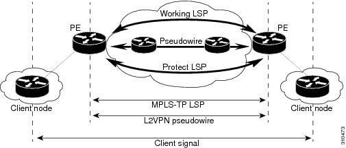
MPLS-TP Path Protection
MPLS-TP label switched paths (LSPs) support 1-to-1 path protection. There are two types of LSPs: protect LSPs and working LSPs. You can configure the both types of LSPs when configuring the MPLS-TP tunnel. The working LSP is the primary LSP used to route traffic. The protect LSP acts as a backup for a working LSP. If the working LSP fails, traffic is switched to the protect LSP until the working LSP is restored, at which time forwarding reverts back to the working LSP.
Bidirectional LSPs
Multiprotocol Label Switching Transport Profile (MPLS-TP) label switched paths (LSPs) are bidirectional and co-routed. They comprise of two unidirectional LSPs that are supported by the MPLS forwarding infrastructure. A TP tunnel consists of a pair of unidirectional tunnels that provide a bidirectional LSP. Each unidirectional tunnel can be optionally protected with a protect LSP that activates automatically upon failure conditions.
Support for MPLS Transport Profile OAM
Several Operations, Administration, and Maintenance (OAM) protocols and messages support the provisioning and maintenance of Multiprotocol Label Switching Transport Profile (MPLS-TP) tunnels and bidirectional label switched paths (LSPs).
The following OAM messages are forwarded along the specified MPLS LSP:
- OAM Fault Management—Alarm Indication Signal (AIS), Link Down Indication (LDI), and Lock Report (LKR) messages (GAL with BFD messages).
- OAM Connection Verification—Ping and traceroute messages (GAL with IP channel by default).
- OAM Continuity Check—Bidirectional Forwarding Detection (BFD) messages—non-IP BFD and IP BFD (GAL with non-IP BFD channel or IP BFD channel depending on message format).
- The following messages are forwarded along the specified pseudowire:
- MPLS-TP OAM Fault Management (LDI, AIS, and LKR messages)—LDI messages are AIS messages whose L-flags are set. The LDI messages are generated at midpoint nodes when a failure is detected. From the midpoint, an LDI message is sent to the endpoint that is reachable with the existing failure. Similarly, LKR messages are sent from a midpoint node to the reachable endpoint when an interface is administratively shut down. By default, the reception of LDI and LKR messages on the active LSP at an endpoint will cause a path protection switchover, whereas the reception of an AIS message will not.
- MPLS-TP OAM Fault Management with Emulated Protection Switching for LSP Lockout—Cisco implements a form of Emulated Protection Switching to support LSP Lockout using customized Fault messages. When a Lockout message is sent, it does not cause the LSP to be administratively down. The Cisco Lockout message causes a path protection switchover and prevents data traffic from using the LSP. The LSP remains administratively up so that BFD and other OAM messages can continue to traverse it and so that maintenance of the LSP can take place (such as reconfiguring or replacing a midpoint LSR). After OAM verifies the LSP connectivity, the Lockout is removed and the LSP is brought back to service. Lockout of the working LSP is not allowed if a protect LSP is not configured. Conversely, the Lockout of a protect LSP is allowed if a working LSP is not configured.
- LSP ping and trace—To verify MPLS-TP connectivity, use the ping mpls tp and trace mpls tp commands. You can specify that echo requests be sent along the working LSP, the protect LSP, or the active LSP. You can also specify that echo requests be sent on a locked-out MPLS-TP tunnel LSP (either working or protected) if the working or protected LSP is explicitly specified. You can also specify ping/trace messages with or without IP.
- MPLS-TP OAM Continuity Check (CC) via BFD and Remote Defect Indication (RDI)—RDI is communicated via the BFD diagnostic field in BFD CC messages. BFD sessions run on both the working LSP and the protect LSP. To perform a path protection switchover within 60 milliseconds on an MPLS-TP endpoint, use the BFD Hardware Offload feature, which enables the router hardware to construct and send BFD messages, removing the task from the software path. The BFD Hardware Offload feature is enabled automatically on supported platforms.
MPLS-TP OAM GACH—Generic Associated Channel (G-ACh) is the control channel mechanism associated with Multiprotocol Label Switching (MPLS) LSPs in addition to MPLS pseudowire. The G-ACh Label (GAL) (Label 13) is a generic alert label to identify the presence of the G-ACh in the label packet. It is taken from the reserved MPLS label space. G-ACh/GAL supports OAMs of LSPs and in-band OAMs of pseudowires (PWs). OAM messages are used for fault management, connection verification, continuity check, and so on.
MPLS Transport Profile Static and Dynamic Multisegment Pseudowires
Multiprotocol Label Switching Transport Profile (MPLS-TP) supports the following combinations of static and dynamic multisegment pseudowires:
MPLS-TP OAM Status for Static and Dynamic Multisegment Pseudowires
With static pseudowires, status notifications can be provided by BFD over VCCV or by the static pseudowire OAM protocol. However, BFD over VCCV sends only attachment circuit status code notifications. Hop-by-hop notifications of other pseudowire status codes are not supported. Therefore, the static pseudowire OAM protocol is preferred. You can acquire per pseudowire OAM for attachment circuit/pseudowire notification over the VCCV channel with or without the control word.
MPLS Transport Profile Links and Physical Interfaces
Multiprotocol Label Switching Transport Profile (MPLS-TP) link numbers may be assigned to physical interfaces only. Bundled interfaces and virtual interfaces are not supported for MPLS-TP link numbers.
The MPLS-TP link creates a layer of indirection between the MPLS-TP tunnel and midpoint LSP configuration and the physical interface. The mpls tp link command is used to associate an MPLS-TP link number with a physical interface and next-hop node. On point-to-point interfaces or Ethernet interfaces designated as point-to-point using the medium p2p command, the next-hop can be implicit, so the mpls tp link command just associates a link number to the interface.
Multiple tunnels and LSPs may then refer to the MPLS-TP link to indicate that they are traversing that interface. You can move the MPLS-TP link from one interface to another without reconfiguring all the MPLS-TP tunnels and LSPs that refer to the link.
Link numbers must be unique on the router or node.
See the section Configuring MPLS-TP Links and Physical Interfaces, for more information.
Tunnel Midpoints
Tunnel LSPs, whether endpoint or midpoint, use the same identifying information. However, it is entered differently.
- At the midpoint, all information for the LSP is specified with the mpls tp lsp command for configuring forward and reverse information for forwarding.
- At the midpoint, determining which end is source and which is destination is arbitrary. That is, if you are configuring a tunnel between your device and a coworker’s device, then your device is the source. However, your coworker considers his or her device to be the source. At the midpoint, either device could be considered the source. At the midpoint, the forward direction is from source to destination, and the reverse direction is from destination to source.
- At the endpoint, the local information (source) either comes from the global device ID and global ID, or from the locally configured information using the tp source command.
- At the endpoint, the remote information (destination) is configured using the tp destination command after you enter the interface tunnel-tp number command. The tp destination command includes the destination node ID, and optionally the global ID and the destination tunnel number. If you do not specify the destination tunnel number, the source tunnel number is used.
- At the endpoint, the LSP number is configured in working-lsp or protect-lsp submode. The default is 0 for the working LSP and 1 for the protect LSP.
- When configuring LSPs at midpoint devices, ensure that the configuration does not deflect traffic back to the originating node.
MPLS-TP Linear Protection with PSC Support
MPLS-TP Linear Protection with PSC Support Overview
The Multiprotocol Label Switching (MPLS) Transport Profile (TP) enables you to create tunnels that provide the transport network service layer over which IP and MPLS traffic traverse.
Network survivability is the ability of a network to recover traffic deliver following failure, or degradation, of network resources. The MPLS-TP Survivability Framework (RFC-6372) describes the framework for survivability in MPLS-TP networks, focusing on mechanisms for recovering MPLS-TP label switched paths (LSPs)
Linear protection provides rapid and simple protection switching because it can operate between any pair of points within a network. Protection switching is a fully allocated survivability mechanism, meaning that the route and resources of the protection path are reserved for a selected working path or set of working paths. For a point-to-point LSPs, the protected domain is defined as two label edge routers (LERs) and the transport paths that connect them.
Protection switching in a point-to-point domain can be applied to a 1+1, 1:1, or 1:n unidirectional or bidirectional protection architecture. When used for bidirectional switching, the protection architecture must also support a Protection State Coordination (PSC) protocol. This protocol is used to help coordinate both ends of the protected domain in selecting the proper traffic flow. For example, if either endpoint detects a failure on the working transport entity, the endpoint sends a PSC message to inform the peer endpoint of the state condition. The PSC protocol decides what local action, if any, should be taken.
The following figure shows the MPLS-TP linear protection model used and the associated PSC signaling channel for state coordination.

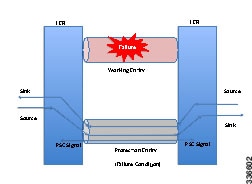
In 1:1 bidirectional protection switching, for each direction, the source endpoint sends traffic on either a working transport entity or a protected transport entity, referred to as a data-path. If the either endpoint detects a failure on the working transport entity, that endpoint switches to send and receive traffic from the protected transport entity. Each endpoint also sends a PSC message to inform the peer endpoint of the state condition. The PSC mechanism is necessary to coordinate the two transport entity endpoints and implement 1:1 bidirectional protection switching even for a unidirectional failure. The switching of the transport path from working path to protected path can happen because of various failure conditions (such as link down indication (LDI), remote defect indication (RDI), and link failures) or because administrator/operator intervention (such as shutdown, lockout of working/forced switch (FS), and lockout of protection).
Each endpoint LER implements a PSC architecture that consists of multiple functional blocks. They are:
- Local Trigger Logic: This receives inputs from bidirectional forwarding detection (BFD), operator commands, fault operation, administration, and maintenance (OAM) and a wait-to-restore (WTR) timer. It runs a priority logic to decide on the highest priority trigger.
- PSC FSM: The highest priority trigger event drives the PSC finite state machine (FSM) logic to decide what local action, if any, should be taken. These actions may include triggering path protection at the local endpoint or may simply ignore the event.
- Remote PSC Signaling: In addition to receiving events from local trigger logic, the PSC FSM logic also receives and processes PSC signaling messages from the remote LER. Remote messages indicate the status of the transport path from the viewpoint of the far end LER. These messages may drive state changes on the local entity.
- PSC Message Generator: Based on the action output from the PSC control logic, this functional block formats the PSC protocol message and transmits it to the remote endpoint of the protected domain. This message may either be the same as the previously transmitted message or change when the PSC control has changed. The messages are transmitted as an initial burst followed by a regular interval.
- Wait-to-Restore Timer: The (configurable) WTR timer is used to delay reversion to a normal state when recovering from a failure condition on the working path in revertive mode. The PSC FSM logic starts/stops the WTR timer based on internal conditions/state. When the WTR expires, it generates an event to drive the local trigger logic.
- Remote Event Expire Timer: The (configurable) remote-event-expire timer is used to clear the remote event after the timer is expired because of remote inactivity or fault in the protected LSP. When the remote event clear timer expires, it generates a remote event clear notification to the PSC FSM logic.
Interoperability With Proprietary Lockout
An emulated protection (emulated automatic protection switching (APS)) switching ensures synchronization between peer entities. The emulated APS uses link down indication (LDI)message (proprietary) extensions when a lockout command is issued on the working or protected LSP. This lockout command is known as emLockout. A lockout is mutually exclusive between the working and protected LSP. In other words, when the working LSP is locked, the protected LSP cannot be locked (and vice versa).
The emLockout message is sent on the specified channel from the endpoint on the LSP where the lockout command (working/protected) is issued. Once the lockout is cleared locally, a Wait-To-Restore (WTR) timer (configurable) is started and the remote end notified. The local peer continues to remain in lockout until a clear is received from the remote peer and the WTR timer has expired and only then the LSP is considered to be no longer locked out. In certain deployments, you use a large WTR timer to emulate a non-revertive behavior. This causes the protected LSP to continue forwarding traffic even after the lockout has been removed from the working LSP.
The PSC protocol as specified in RFC-6378 is incompatible with the emulated APS implementation in certain conditions. For example, PSC implements a priority scheme whereby a lockout of protection (LoP) is at a higher priority than a forced switch (FS) issued on a working LSP. When an FS is issued and cleared, PSC states that the switching must revert to the working LSP immediately. However, the emulated APS implementation starts a WTR timer and switches after the timer has expired.
An endpoint implementing the newer PSC version may have to communicate with another endpoint implementing an older version. Because there is no mechanism to exchange the capabilities, the PSC implementation must interoperate with another peer endpoint implementing emulated APS. In this scenario, the new implementation sends both the LDI extension message (referred to as emLockout) as well as a PSC message when the lockout is issued.
Mapping and Priority of emlockout
There are two possible setups for interoperability:
You can understand the mapping and priority when an emLockout is received and processed in the new-old implementation by referring to the following figure.
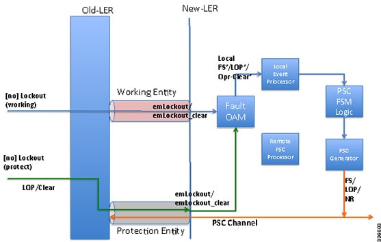
When the new label edge router (new-LER) receives an emLockout (or emLockout_clear) message, the new-LER maps the message into an internal local FS’/FSc’ (local FS-prime/FS-prime-clear) or LoP’/LoPc’ (local LoP-prime/Lop-prime-clear) event based on the channel on which it is received. This event is prioritized by the local event processor against any persistent local operator command. The highest priority event drives the PSC FSM logic and any associated path protection logic. A new internal state is defined for FS’/FSc’ events. The PSC FSM logic transmits the corresponding PSC message. This message is dropped/ignored by the old-LER.
In the new-new LER implementation shown in the following figure, each endpoint generates two messages when a lockout command is given on a working or protected LSP.
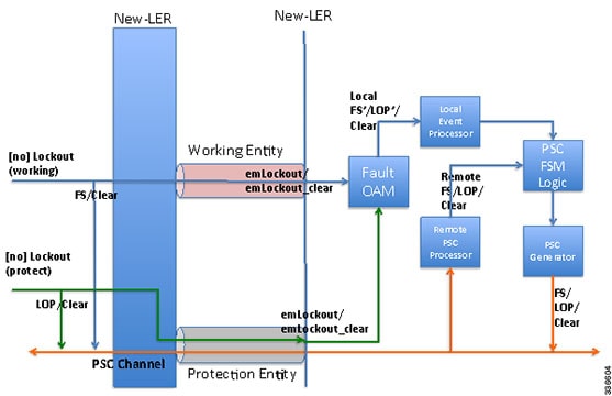
When a lockout (working) command is issued, the new-LER implementation sends an emLockout command on the working LSP and PSC(FS) on the protected LSP. The remote peer receives two commands in either order. A priority scheme for local events is modified slightly beyond what is defined in order to drive the PSC FSM to a consistent state despite the order in which the two messages are received.
In the new implementation, it is possible to override the lockout of the working LSP with the lockout of the protected LSP according to the priority scheme. This is not allowed in the existing implementation. Consider the following steps between old (O) and new (N) node setup:
Time T1: Lockout (on the working LSP) is issued on O and N. Data is switched from the working to the protected LSP.
Time T2: Lockout (on the protected LSP) is issued on O and N. The command is rejected at O (existing behavior) and accepted at N (new behavior). Data in O->N continues on the protected LSP. Data in N->O switches to the working LSP.
You must issue a clear lockout (on the working LSP) and re-issue a lockout (on the protected LSP) on the old node to restore consistency.
WTR Synchronization
When a lockout on the working label switched path (LSP) is issued and subsequently cleared, a WTR timer (default: 10 sec, configurable) is started. When the timer expires, the data path is switched from protected to working LSP.
The PSC protocol indicates that the switch should happen immediately when a lockout (FS) is cleared.
When a new node is connected to the old node, for a period of time equal to the WTR timer value, the data path may be out-of-sync when a lockout is cleared on the working LSP. You should configure a low WTR value in order to minimize this condition.
Another issue is synchronization of the WTR value during stateful switchover (SSO). Currently, the WTR residual value is not checkpointed between the active and standby. As a result, after SSO, the new active restarts the WTR with the configured value if the protected LSP is active and the working LSP is up. As part of the PSC protocol implementation, the residual WTR is checkpointed on the standby. When the standby becomes active, the WTR is started with the residual value.
Priority of Inputs
The event priority scheme for locally generated events is as follows in high to low order:
Local Events:
1. Opr-Clear (Operator Clear)
2. LoP (Lockout of Protection)
3. LoP’/LoP’-Clear
4. FS (Forced Switch)
5. FS’/FS’-Clear
6. MS (Manual-Switch)
The emLockout received on the working LSP is mapped to the local-FS’. The emLockout received on the protected LSP is mapped to the local-LoP’. The emLockout-clear received is mapped to the corresponding clear events.
The priority definition for Signal Fail (SF), Signal Degrade (SD), Manual Switch (MS), WTR, Do Not Revert (DNR), and No Request (NR) remains unchanged.
PSC Finite State Machine Logic
The PSC implementation follows the state transition logic defined in the following tables:
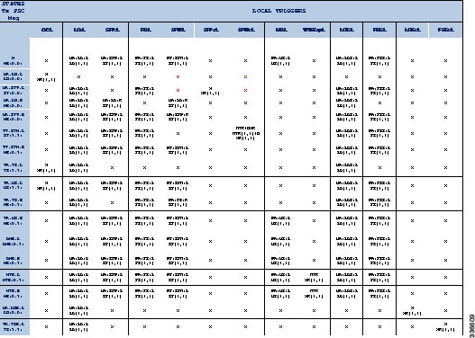
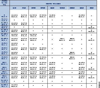
The PSC finite state machine (FSM) consists of the following states used in the above tables:
1. Normal state.
2. UA:LO:L Protect is unavailable because of a lockout protection issued locally.
3. UA:LOE:L Protect is unavailable because of receipt of emLockout on the protected LSP.
4. UA:LO:R Protect is unavailable because of a lockout of protection issued remotely.
5. UA:SFP:L Protect is unavailable because of a local sgnal fail on the protected LSP.
6. UA:SFP:R Protect is unavailable because of a remote signal fail on the protected LSP.
7. PF:SFW:L Protecting failure because of a local signal fail on the working LSP.
8. PF:SFW:R Protecting failure because of a remote signal fail on the working LSP.
9. PA:FS:L Protecting administrative because of a local force switch (FS).
10. PA:FS:R Protecting administrative because of a remote FS.
11. PA:FSE:R Protecting administrative because of a receipt of emLockout on the working LSP.
12. PA:MS:L Protecting administrative because of a local manual switch.
13. PA:MS:R Protecting administrative because of a remote manual switch.
14. WTR:L Local wait-to-restore (WTR) state.
15. WTR:R Remote WTR state.
16. DNR:L Local do-not-revert (DNR) state.
17. DNR:R Remote DNR state.
The following are the PSC FSM events based on priority (higher to lower):
1. OC:L Local operator command cleared.
2. LO:L Local lockout of protect command.
3. LOEc:L Receipt of emLockout clear of protect.
4. LOE:L Receipt of emLockout on the protected LSP.
5. LO:R Remote lockout of protection.
6. FS:L Local FS.
7. FSEc:L Receipt of emLockout clear of the working LSP.
8. FSE:L Receipt of emLockout of the working LSP.
9. FS:R Remote FS.
10. SFP:L Local signal fail on the protected LSP.
11. SFP:R Remote signal fail on the protected LSP.
12. SFW:L Local signal fail on the working LSP.
13. SFW:R Remote signal fail on the working LSP.
14. SFPc:L Local signal fail on protect cleared.
15. SFWc:L Local signal fail on the working cleared.
16. MS:L Local manual switch.
17. MS:R Remote manual switch.
18. WTRExp:L Local WTR timer expired.
19. WTR:R Remote WTR event.
20. DNR:R Remote DNR event.
21. NR:R Remote NR event.
The signal-degrade event on the working/protected LSP is not supported.
PSC Syslogs
The following are the new syslogs that are introduced as part of the Linear Protection with PSC Support feature:
| SYSLOG NAME | DESCRIPTION | RAW FORMAT |
| MPLS_TP_TUNNEL_PSC_PREEMPTION | Handle MPLS TP tunnel PSC event preemption syslog. | %MPLS-TP-5-PSCPREEMPTION: Tunnel-tp10, PSC Event: LOP:R preempted PSC Event: FS:L |
| MPLS_TP_TUNNEL_PSC_TYPE_MISMATCH | Handle MPLS TP tunnel type mismatch | %MPLS-PSC-5-TYPE-MISMATCH: Tunnel-tp10, type mismatch local-type: 1:1, |
How to Configure MPLS Transport Profile
- Configuring the MPLS Label Range
- Configuring the Router ID and Global ID
- Configuring Bidirectional Forwarding Detection Templates
- Configuring Pseudowire OAM Attributes
- Configuring the Pseudowire Class
- Configuring the Pseudowire
- Configuring the MPLS-TP Tunnel
- Configuring MPLS-TP LSPs at Midpoints
- Configuring MPLS-TP Links and Physical Interfaces
- Configuring Static-to-Static Multisegment Pseudowires for MPLS-TP
- Configuring a Template with Pseudowire Type-Length-Value Parameters
- Configuring MPLS-TP Linear Protection with PSC Support
- Configuring Static-to-Dynamic Multisegment Pseudowires for MPLS-TP
- Verifying the MPLS-TP Configuration
Configuring the MPLS Label Range
You must specify a static range of Multiprotocol Label Switching (MPLS) labels using the mpls label range command with the static keyword.
1.
enable
2.
configure
terminal
3.
mpls
label
range
minimum-value
maximum-value
static minimum-static-value maximum-static-value
4.
end
DETAILED STEPS
Configuring the Router ID and Global ID
1.
enable
2.
configure
terminal
3.
mpls
tp
4.
router-id
node-id
5.
global-id
num
6.
end
DETAILED STEPS
Configuring Bidirectional Forwarding Detection Templates
The bfd-template command allows you to create a BFD template and enter BFD configuration mode. The template can be used to specify a set of BFD interval values. You invoke the template as part of the MPLS-TP tunnel. On platforms that support the BFD Hardware Offload feature and that can provide a 60-ms cutover for MPLS-TP tunnels, it is recommended to use the higher resolution timers in the BFD template.
1.
enable
2.
configure
terminal
3.
bfd-template
single-hop
template-name
4.
interval
[microseconds] {both time | min-tx time min-rx time} [multiplier multiplier-value]
5.
end
DETAILED STEPS
Configuring Pseudowire OAM Attributes
1.
enable
2.
configure
terminal
3.
pseudowire-static-oam
class
class-name
4.
timeout
refresh
send
seconds
5.
exit
DETAILED STEPS
Configuring the Pseudowire Class
When you create a pseudowire class, you specify the parameters of the pseudowire, such as the use of the control word, preferred path, OAM class, and VCCV BFD template.
1.
enable
2.
configure
terminal
3.
pseudowire-class
class-name
4.
encapsulation
mpls
5.
control-word
6.
protocol
{l2tpv2 | l2tpv3 | none} [l2tp-class-name]
7.
preferred-path {interface tunnel tunnel-number | peer {ip-address | host-name}} [disable-fallback]
8.
status
protocol
notification
static
class-name
9.
vccv
bfd
template
name
[udp | raw-bfd]
10.
end
DETAILED STEPS
Configuring the Pseudowire
1.
enable
2.
configure
terminal
3.
interface
type
number
4.
xconnect
peer-ip-address
vc-id
{encapsulation
{l2tpv3 [manual] |
mpls [manual]} |
pw-class pw-class-name}
[pw-class pw-class-name]
[sequencing {transmit |
receive |
both}]
5.
mpls
label
local-pseudowire-label
remote-pseudowire-label
6.
mpls
control-word
7.
backup
delay
{enable-delay-period |
never}
{disable-delay-period |
never}
8.
backup
peer
peer-router-ip-addr
vcid
[pw-class pw-class-name]
[priority value]
9.
end
DETAILED STEPS
Configuring the MPLS-TP Tunnel
On the endpoint devices, create an MPLS TP tunnel and configure its parameters. See the interface tunnel-tp command for information on the parameters.
1.
enable
2.
configure
terminal
3.
interface
tunnel-tp
number
4.
description
tunnel-description
5.
tp
tunnel-name
name
6.
tp
bandwidth
num
7.
tp
source
node-id
[global-id num]
8.
tp
destination
node-id
[tunnel-tp num[ global-id num]]
9.
bfd
bfd-template
10.
working-lsp
11.
in-label
num
12.
out-label
num
out-link
num
13.
exit
14.
protect-lsp
15.
in-label
num
16.
out-label
num
out-link
num
17.
end
DETAILED STEPS
Configuring MPLS-TP LSPs at Midpoints
 Note | When configuring LSPs at midpoint devices, ensure that the configuration does not deflect traffic back to the originating node. |
1.
enable
2.
configure
terminal
3.
mpls
tp
lsp
source
node-id
[global-id
num]
tunnel-tp
num
lsp{lsp-num |
protect |
working}
destination
node-id
[global-id
num]
tunnel-tp
num
4.
forward-lsp
5.
bandwidth
num
6.
in-label
num
out-label
num
out-link
num
7.
exit
8.
reverse-lsp
9.
bandwidth
num
10.
in-label
num
out-label
num
out-link
num
11.
end
DETAILED STEPS
Configuring MPLS-TP Links and Physical Interfaces
MPLS-TP link numbers may be assigned to physical interfaces only. Bundled interfaces and virtual interfaces are not supported for MPLS-TP link numbers.
1.
enable
2.
configure
terminal
3.
interface
type number
4.
ip
address
ip-address
mask
5.
mpls
tp
link
link-num
{ipv4 ip-address | tx-mac mac-address} rx-mac mac-address
6.
ip
rsvp
bandwidth
[rdm [bc0 interface-bandwidth] [[single-flow-bandwidth [bc1 bandwidth | sub-pool bandwidth]]] [interface-bandwidth [single-flow-bandwidth [bc1 bandwidth | sub-pool bandwidth]] | mam max-reservable-bw [interface-bandwidth [single-flow-bandwidth] [bc0 interface-bandwidth [bc1 bandwidth]]] | percent percent-bandwidth [single-flow-bandwidth]]
7.
end
8.
show
mpls
tp
link-numbers
DETAILED STEPS
Configuring Static-to-Static Multisegment Pseudowires for MPLS-TP
1.
enable
2.
configure
terminal
3.
l2
vfi
name
point-to-point
4.
neighbor
ip-address
vc-id
{encapsulation mpls | pw-class pw-class-name}
5.
mpls
label
local-pseudowire-label
remote-pseudowire-label
6.
mpls
control-word
7.
neighbor
ip-address
vc-id
{encapsulation mpls | pw-class pw-class-name}
8.
mpls
label
local-pseudowire-label
remote-pseudowire-label
9.
mpls
control-word
10.
end
DETAILED STEPS
Configuring a Template with Pseudowire Type-Length-Value Parameters
1.
enable
2.
configure
terminal
3.
pseudowire-tlv
template
template-name
4.
tlv [type-name] type-value length [dec | hexstr | str] value
5.
end
DETAILED STEPS
| Command or Action | Purpose | |
|---|---|---|
| Step 1 |
enable
Example: Device> enable |
Enables privileged EXEC mode. |
| Step 2 |
configure
terminal
Example: Device# configure terminal |
Enters global configuration mode. |
| Step 3 |
pseudowire-tlv
template
template-name
Example: Device(config)# pseudowire-tlv template statictemp |
Creates a template of pseudowire type-length-value (TLV) parameters and enters pseudowire TLV template configuration mode. |
| Step 4 |
tlv [type-name] type-value length [dec | hexstr | str] value Example: Device(config-pw-tlv-template)# tlv statictemp 2 4 hexstr 1 |
Specifies the TLV parameters. |
| Step 5 |
end Example: Device(config-pw-tlv-template)# end |
Exits pseudowire TLV template configuration mode and returns to privileged EXEC mode. |
Configuring MPLS-TP Linear Protection with PSC Support
The psc command allows you to configure MPLS-TP linear protection with PSC support. PSC is disabled by default. However, it can be enabled by issuing the psc command.
1.
enable
2.
configure terminal
3.
mpls tp
4.
psc
5.
psc fast refresh interval time-in-msec
6.
psc slow refresh interval time-in-msec
7.
psc remote refresh interval time-in-sec message-count num
8.
exit
9.
interface tunnel-tp number
10.
psc
11.
emulated-lockout
12.
working-lsp
13.
manual-switch
14.
exit
15.
exit
DETAILED STEPS
| Command or Action | Purpose | |
|---|---|---|
| Step 1 |
enable
Example: Device> enable |
Enables privileged EXEC mode. |
| Step 2 |
configure terminal
Example: Device# configure terminal |
Enters global configuration mode. |
| Step 3 |
mpls tp
Example: Device(config)# mpls tp |
Enters Multiprotocol Label Switching (MPLS) Transport Profile (TP) global mode. |
| Step 4 |
psc
Example: Device(config-mpls-tp)# psc |
Enables the PSC Protocol. |
| Step 5 | psc fast refresh interval time-in-msec Example: Device(config-mpls-tp)# psc fast refresh interval 2000 | Configures the fast refresh interval for PSC messages. |
| Step 6 | psc slow refresh interval time-in-msec Example: Device(config-mpls-tp)# psc slow refresh interval 10 | Configures the slow refresh interval for PSC messages. |
| Step 7 | psc remote refresh interval time-in-sec message-count num Example: Device(config-mpls-tp)# psc remote refresh interval 20 message-count 15 | Configures the remote-event expiration timer. |
| Step 8 | exit Example: Device(config-mpls-tp)# exit | Exits MPLS TP global mode. |
| Step 9 | interface tunnel-tp number Example: Device(config)# interface tunnel-tp 1 | Creates an MPLS-TP tunnel called number and enters TP interface tunnel mode. |
| Step 10 | psc Example: Device(config-if)# psc | Enables PSC. By default, PSC is disabled. |
| Step 11 | emulated-lockout Example: Device(config-if)# emulated-lockout | Enables the sending of emLockout on working/protected transport entities if the lockout command is issued on each working/protected transport entity respectively. By default, the sending of emLockout is disabled. |
| Step 12 | working-lsp Example: Device(config-if)# working-lsp | Enters working LSP mode on a TP tunnel interface. |
| Step 13 | manual-switch Example: Device(config-if-working)# manual-switch | Issues a local manual switch condition on a working label switched path (LSP). This can be configured only in working LSP mode on a TP tunnel interface. |
| Step 14 | exit Example: Device(config-if-working)# exit | Exits working LSP mode. |
| Step 15 | exit Example: Device(config-if)# exit | Exits TP interface tunnel mode. |
Configuring Static-to-Dynamic Multisegment Pseudowires for MPLS-TP
When you configure static-to-dynamic pseudowires, you configure the static pseudowire class with the protocol none command, create a dynamic pseudowire class, and then invoke those pseudowire classes with the neighbor commands.
1.
enable
2.
configure
terminal
3.
pseudowire-class
class-name
4.
encapsulation
mpls
5.
control-word
6.
protocol {l2tpv2 | l2tpv3 | none} [l2tp-class-name]
7.
exit
8.
pseudowire-class
class-name
9.
encapsulation
mpls
10.
exit
11.
l2
vfi
name
point-to-point
12.
neighbor
ip-address
vc-id {encapsulation mpls | pw-class pw-class-name}
13.
neighbor
ip-address
vc-id {encapsulation mpls | pw-class pw-class-name}
14.
mpls
label
local-pseudowire-label
remote-pseudowire-label
15.
mpls
control-word
16.
local
interface
pseudowire-type
18.
end
DETAILED STEPS
| Command or Action | Purpose | |||
|---|---|---|---|---|
| Step 1 |
enable
Example: Device> enable |
Enables privileged EXEC mode. | ||
| Step 2 |
configure
terminal
Example: Device# configure terminal |
Enters global configuration mode. | ||
| Step 3 |
pseudowire-class
class-name
Example: Device(config)# pseudowire-class mpls-tp-class1 |
Creates a pseudowire class and enters pseudowire class configuration mode. | ||
| Step 4 |
encapsulation
mpls
Example: Device(config-pw-class)# encapsulation mpls |
Specifies the encapsulation type. | ||
| Step 5 |
control-word
Example: Device(config-pw-class)# control-word |
Enables the use of the control word. | ||
| Step 6 |
protocol {l2tpv2 | l2tpv3 | none} [l2tp-class-name] Example: Device(config-pw-class)# protocol none |
Specifies the type of protocol. Use the protocol none command to specify a static pseudowire. | ||
| Step 7 |
exit
Example: Device(config-pw-class)# exit |
Exits pseudowire class configuration mode and returns to global configuration mode. | ||
| Step 8 |
pseudowire-class
class-name
Example: Device(config)# pseudowire-class mpls-tp-class1 |
Creates a pseudowire class and enters pseudowire class configuration mode. | ||
| Step 9 |
encapsulation
mpls
Example: Device(config-pw-class)# encapsulation mpls |
Specifies the encapsulation type. | ||
| Step 10 |
exit
Example: Device(config-pw-class)# exit |
Exits pseudowire class configuration mode and returns to global configuration mode. | ||
| Step 11 |
l2
vfi
name
point-to-point
Example: Device(config)# l2 vfi atom point-to-point |
Creates a point-to-point Layer 2 virtual forwarding interface (VFI) and enters VFI configuration mode. | ||
| Step 12 |
neighbor
ip-address
vc-id {encapsulation mpls | pw-class pw-class-name} Example: Device(config-vfi)# neighbor 10.111.111.111 123 pw-class atom |
Sets up an emulated VC and enters VFI neighbor configuration mode.
| ||
| Step 13 |
neighbor
ip-address
vc-id {encapsulation mpls | pw-class pw-class-name} Example: Device(config-vfi-neighbor)# neighbor 10.111.111.111 123 pw-class atom |
Sets up an emulated VC.
| ||
| Step 14 |
mpls
label
local-pseudowire-label
remote-pseudowire-label
Example: Device(config-vfi-neighbor)# mpls label 101 201 |
Configures the static pseudowire connection by defining local and remote circuit labels. | ||
| Step 15 |
mpls
control-word
Example: Device(config-vfi-neighbor)# mpls control-word |
Specifies the control word. | ||
| Step 16 |
local
interface
pseudowire-type
Example: Device(config-vfi-neighbor)# local interface 4 |
Specifies the pseudowire type. | ||
| Step 17 | Do one of the following:
Example: Device(config-vfi-neighbor)# tlv statictemp 2 4 hexstr 1 |
Specifies the TLV parameters or invokes a previously configured TLV template. | ||
| Step 18 | end Example: Device(config-vfi-neighbor)# end | Ends the session. |
Verifying the MPLS-TP Configuration
Use the following commands to verify and help troubleshoot your MPLS-TP configuration:
- debug mpls tp—Enables the logging of MPLS-TP error messages.
- logging (MPLS-TP)—Displays configuration or state change logging messages.
- show bfd neighbors mpls-tp—Displays the BFD state, which must be up in order for the endpoint LSPs to be up.
- show mpls l2transport static-oam l2transport static-oam—Displays MPLS-TP messages related to pseudowires.
- show mpls tp tunnel-tp number detail—Displays the number and details of the tunnels that are not functioning.
- show mpls tp tunnel-tp lsps—Displays the status of the LSPs, and helps you ensure that both LSPs are up and working from a tunnel endpoint.
- traceroute mpls tp and ping mpls tp—Helps you identify connectivity issues along the MPLS-TP tunnel path.
Configuration Examples for MPLS Transport Profile
Example: Configuring MPLS-TP Linear Protection with PSC Support
The following example enters MPLS TP global mode and enables the PSC Protocol.
Device> enable
Device# configure terminal
Device(config)# mpls tp
Device(config-mpls-tp)# psc
The following example configures the fast refresh interval for PSC messages. The interval value is 2000 seconds.
Device(config-mpls-tp)# psc fast refresh interval 2000
The following example configures the slow refresh interval for PSC messages. The interval value is 10 seconds.
Device(config-mpls-tp)# psc slow refresh interval 10
The following example configures the remote event expiration timer with a refresh interval value of 20 seconds with a message count of 15.
Device(config-mpls-tp)# psc remote refresh interval 20 message-count 15
The following example exits MPLS TP global mode, creates a TP interface tunnel, and enables PSC.
Device(config-mpls-tp)# exit
Decice(config) interface tunnel-tp 1
Device(config-if)# psc
The following example enables the sending of emLockout on working/protected transport entities, enters working LSP mode on a TP tunnel interface, and issues a local manual switch condition on a working LSP.
Device(config-if)# emulated-lockout
Device(config-if)# working-lsp
Device(config-if-working)# manual-switch
Example: Configuring Static-to-dynamic Multisegment Pseudowires for MPLS-TP
The following example shows how to configure static-to-dynamic multisegment pseudowires for Layer 2 VFI.
l2 vfi atom point-to-point (static-dynamic MSPW)
	neighbor 10.116.116.116 4294967295 pw-class dypw (dynamic)
		neighbor 10.111.111.111 123 pw-class stpw (static)
		mpls label 101 201
		mpls control-word
		local interface 4
		tlv mtu 1 4 1500
		tlv description 3 6 str abcd
		tlv descr C 4 hexstr 0505
Example: Verifying MPLS-TP Linear Protection with PSC Support
The following example displays a summary of the MPLS-TP settings.
Device# show mpls tp summary
The following example provides information about the MPLS-TP link number database.
Device# show mpls tp link-numbers
Example: Troubleshooting MPLS-TP Linear Protection with PSC Support
The following example enables debugging for all PSC packets that are sent and received.
Device# debug mpls tp psc packet
The following example enables debugging for all kinds of PSC events.
Device# debug mpls tp psc event
The following example clears the counters for PSC signaling messages based on the tunnel number.
Device# clear mpls tp 1 psc counter
The following example clears the remote event for PSC based on the tunnel number.
Device# clear mpls tp tunnel-tp 1 psc remote-event
Additional References for MPLS Transport Profile
Related Documents
|
Related Topic |
Document Title |
|---|---|
|
Cisco IOS commands |
|
|
MPLS commands |
Standards and RFCs
|
Standard/RFC |
Title |
|---|---|
|
draft-ietf-mpls-tp-gach-gal-xx |
MPLS Generic Associated Channel |
|
RFC 5586 |
MPLS Generic Associated Channel |
|
RFC 5885 |
Bidirectional Forwarding Detection (BFD) for the Pseudowire Virtual Circuit Connectivity Verification (VCCV) |
|
RFC 5921 |
A Framework for MPLS in Transport Networks |
Technical Assistance
|
Description |
Link |
|---|---|
|
The Cisco Support and Documentation website provides online resources to download documentation, software, and tools. Use these resources to install and configure the software and to troubleshoot and resolve technical issues with Cisco products and technologies. Access to most tools on the Cisco Support and Documentation website requires a Cisco.com user ID and password. |
Feature Information for MPLS Transport Profile
The following table provides release information about the feature or features described in this module. This table lists only the software release that introduced support for a given feature in a given software release train. Unless noted otherwise, subsequent releases of that software release train also support that feature.
Use Cisco Feature Navigator to find information about platform support and Cisco software image support. To access Cisco Feature Navigator, go to www.cisco.com/go/cfn. An account on Cisco.com is not required.
Feature Name |
Releases |
Feature Information |
|---|---|---|
|
MPLS Transport Profile
|
Cisco IOS XE Release 3.5S |
MPLS Transport Profile (TP) enables you to create tunnels that provide the transport network service layer over which IP and MPLS traffic traverses. MPLS-TP tunnels enable a transition from SONET and SDH TDM technologies to packet switching to support services with high bandwidth requirements, such as video. In Cisco IOS XE Release 3.5S, support was added for the Cisco ASR 903 Router. The following commands were introduced or modified: debug mpls l2transport static-oam, debug mpls tp, interface tunnel-tp interval local, interface logging (MPLS-TP), medium p2p, mpls tp, mpls tp link, mpls tp lsp ping, notification static timeout refresh, pseudowire-static-oam class, pseudowire-tlv template, show mpls l2transport static-oam, show mpls tp status protocol, tlv, tlv template trace mpls tp. |
MPLS Transport Profile |
Cisco IOS XE Release 3.10S |
In Cisco IOS XE Release 3.10S, support was added for the Cisco ASR 1000 Router. |
MPLS-TP Linear Protection with PSC Support |
Cisco IOS XE Release 3.9S |
In Cisco IOS XE Release 3.9S, support was added for the Cisco ASR 903 Router. The following commands were introduced or modified: [no] psc {fast | slow | remote} refresh interval {time-in-msec |time-in-sec} [message-countnum], emulated-lockout, manual-switch, show mpls tp summary, show mpls tp link-numbers, debug mpls tp psc packet, debug mpls tp psc event, clear mplsl tp [tunnel-tp tun-num| tunnel-name name] psc counter, clear mpls tp [tunnel-tp tun-num| tunnel-name name] psc remote-event. |