- Configuring GLBP
- HSRP for IPv6
- Configuring HSRP
- HSRP Version 2
- HSRP MD5 Authentication
- HSRP Support for ICMP Redirects
- FHRP - HSRP Multiple Group Optimization
- FHRP - HSRP Group Shutdown
- SSO HSRP
- HSRP - ISSU
- FHRP - HSRP MIB
- HSRP Support for MPLS VPNs
- Configuring VRRP
- VRRPv3 Protocol Support
- VRRPv3: Object Tracking Integration
- Virtual Router Redundancy Service
- Index
- Finding Feature Information
- Restrictions for HSRP
- Information About HSRP
- HSRP Operation
- HSRP Version 2 Design
- HSRP Configuration Changes
- HSRP Benefits
- HSRP Groups and Group Attributes
- HSRP Preemption
- HSRP Priority and Preemption
- How Object Tracking Affects the Priority of an HSRP Device
- HSRP Addressing
- HSRP Virtual MAC Addresses and BIA MAC Addresses
- HSRP Timers
- HSRP MAC Refresh Interval
- HSRP Text Authentication
- HSRP MD5 Authentication
- HSRP Support for IPv6
- HSRP Messages and States
- HSRP Group Linking to IP Redundancy Clients
- HSRP Object Tracking
- HSRP Group Shutdown
- HSRP Support for ICMP Redirect Messages
- ICMP Redirects to Active HSRP Devices
- ICMP Redirects to Passive HSRP Devices
- ICMP Redirects to Non-HSRP Devices
- Passive HSRP Advertisement Messages
- ICMP Redirects Not Sent
- HSRP Support for MPLS VPNs
- HSRP Multiple Group Optimization
- HSRP—ISSU
- SSO HSRP
- HSRP BFD Peering
- HSRP MIB Traps
- How to Configure HSRP
- Enabling HSRP
- Delaying the Initialization of HSRP on an Interface
- Configuring HSRP Priority and Preemption
- Configuring HSRP Object Tracking
- Configuring HSRP MD5 Authentication Using a Key String
- Configuring HSRP MD5 Authentication Using a Key Chain
- Troubleshooting HSRP MD5 Authentication
- Configuring HSRP Text Authentication
- Configuring HSRP Timers
- Configuring an HSRP MAC Refresh Interval
- Configuring Multiple HSRP Groups for Load Balancing
- Improving CPU and Network Performance with HSRP Multiple Group Optimization
- Enabling HSRP Support for ICMP Redirect Messages
- Configuring HSRP Virtual MAC Addresses or BIA MAC Addresses
- Linking IP Redundancy Clients to HSRP Groups
- Changing to HSRP Version 2
- Enabling SSO Aware HSRP
- Verifying SSO Aware HSRP
- Enabling HSRP MIB Traps
- Configuring BFD Session Parameters on an Interface
- Configuring HSRP BFD Peering
- Verifying HSRP BFD Peering
- Configuration Examples for HSRP
- Example: Configuring HSRP Priority and Preemption
- Example: Configuring HSRP Object Tracking
- Example: Configuring HSRP Group Shutdown
- Example: Configuring HSRP MD5 Authentication Using Key Strings
- Example: Configuring HSRP MD5 Authentication Using Key Chains
- Example: Configuring HSRP MD5 Authentication Using Key Strings and Key Chains
- Example: Configuring HSRP Text Authentication
- Example: Configuring Multiple HSRP Groups for Load Balancing
- Example: Improving CPU and Network Performance with HSRP Multiple Group Optimization
- Example: Configuring HSRP Support for ICMP Redirect Messages
- Example: Configuring HSRP Virtual MAC Addresses and BIA MAC Address
- Example: Linking IP Redundancy Clients to HSRP Groups
- Example: Configuring HSRP Version 2
- Example: Enabling SSO-Aware HSRP
- Example: Enabling HSRP MIB Traps
- Example: HSRP BFD Peering
- Additional References
- Feature Information for HSRP
- Glossary
Configuring HSRP
The Hot Standby Router Protocol (HSRP) is a First Hop Redundancy Protocol (FHRP) designed to allow for transparent failover of the first-hop IP device. HSRP provides high network availability by providing first-hop routing redundancy for IP hosts on networks configured with a default gateway IP address. HSRP is used in a group of routers for selecting an active device and a standby device. In a group of device interfaces, the active device is the device of choice for routing packets; the standby device is the device that takes over when the active device fails or when preset conditions are met.
- Finding Feature Information
- Restrictions for HSRP
- Information About HSRP
- How to Configure HSRP
- Configuration Examples for HSRP
- Additional References
- Feature Information for HSRP
- Glossary
Finding Feature Information
Your software release may not support all the features documented in this module. For the latest caveats and feature information, see Bug Search Tool and the release notes for your platform and software release. To find information about the features documented in this module, and to see a list of the releases in which each feature is supported, see the feature information table.
Use Cisco Feature Navigator to find information about platform support and Cisco software image support. To access Cisco Feature Navigator, go to www.cisco.com/go/cfn. An account on Cisco.com is not required.
Restrictions for HSRP
Information About HSRP
- HSRP Operation
- HSRP Version 2 Design
- HSRP Configuration Changes
- HSRP Benefits
- HSRP Groups and Group Attributes
- HSRP Preemption
- HSRP Priority and Preemption
- How Object Tracking Affects the Priority of an HSRP Device
- HSRP Addressing
- HSRP Virtual MAC Addresses and BIA MAC Addresses
- HSRP Timers
- HSRP MAC Refresh Interval
- HSRP Text Authentication
- HSRP MD5 Authentication
- HSRP Support for IPv6
- HSRP Messages and States
- HSRP Group Linking to IP Redundancy Clients
- HSRP Object Tracking
- HSRP Group Shutdown
- HSRP Support for ICMP Redirect Messages
- ICMP Redirects to Active HSRP Devices
- ICMP Redirects to Passive HSRP Devices
- ICMP Redirects to Non-HSRP Devices
- Passive HSRP Advertisement Messages
- ICMP Redirects Not Sent
- HSRP Support for MPLS VPNs
- HSRP Multiple Group Optimization
- HSRP—ISSU
- SSO HSRP
- HSRP BFD Peering
- HSRP MIB Traps
HSRP Operation
Most IP hosts have an IP address of a single device configured as the default gateway. When HSRP is used, the HSRP virtual IP address is configured as the host’s default gateway instead of the IP address of the device.
HSRP is useful for hosts that do not support a discovery protocol (such as ICMP Router Discovery Protocol [IRDP]) and cannot switch to a new device when their selected device reloads or loses power. Because existing TCP sessions can survive the failover, this protocol also provides a more transparent recovery for hosts that dynamically choose a next hop for routing IP traffic.
When HSRP is configured on a network segment, it provides a virtual MAC address and an IP address that is shared among a group of devices running HSRP. The address of this HSRP group is referred to as the virtual IP address. One of these devices is selected by the protocol to be the active device. The active device receives and routes packets destined for the MAC address of the group. For n devices running HSRP, n+ 1 IP and MAC addresses are assigned.
HSRP detects when the designated active device fails, at which point a selected standby device assumes control of the MAC and IP addresses of the Hot Standby group. A new standby device is also selected at that time.
HSRP uses a priority mechanism to determine which HSRP configured device is to be the default active device. To configure a device as the active device, you assign it a priority that is higher than the priority of all the other HSRP-configured devices. The default priority is 100, so if you configure just one device to have a higher priority, that device will be the default active device.
Devices that are running HSRP send and receive multicast UDP-based hello messages to detect device failure and to designate active and standby devices. When the active device fails to send a hello message within a configurable period of time, the standby device with the highest priority becomes the active device. The transition of packet forwarding functions between devices is completely transparent to all hosts on the network.
You can configure multiple Hot Standby groups on an interface, thereby making fuller use of redundant devices and load sharing.
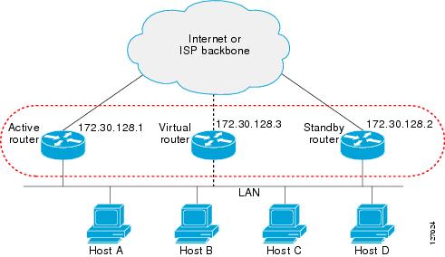
The figure below shows a network configured for HSRP. By sharing a virtual MAC address and IP address, two or more devices can act as a single virtual router. The virtual device does not physically exist but represents the common default gateway for devices that are configured to provide backup to each other. You do not need to configure the hosts on the LAN with the IP address of the active device. Instead, you configure them with the IP address (virtual IP address) of the virtual device as their default gateway. If the active device fails to send a hello message within the configurable period of time, the standby device takes over and responds to the virtual addresses and becomes the active device, assuming the active device duties.
HSRP Version 2 Design
HSRP version 2 is designed to address the following restrictions in HSRP version 1:
-
In HSRP version 1, millisecond timer values are not advertised or learned. HSRP version 2 advertises and learns millisecond timer values. This change ensures stability of the HSRP groups in all cases.
-
In HSRP version 1, group numbers are restricted to the range from 0 to 255. HSRP version 2 expands the group number range from 0 to 4095.
-
HSRP version 2 provides improved management and troubleshooting. With HSRP version 1, you cannot use HSRP active hello messages to identify which physical device sent the message because the source MAC address is the HSRP virtual MAC address. The HSRP version 2 packet format includes a 6-byte identifier field that is used to uniquely identify the sender of the message. Typically, this field is populated with the interface MAC address.
-
The multicast address 224.0.0.2 is used to send HSRP hello messages. This address can conflict with Cisco Group Management Protocol (CGMP) leave processing.
Version 1 is the default version of HSRP.
HSRP version 2 uses the new IP multicast address 224.0.0.102 to send hello packets instead of the multicast address of 224.0.0.2, used by HSRP version 1. This new multicast address allows CGMP leave processing to be enabled at the same time as HSRP.
HSRP version 2 permits an expanded group number range, 0 to 4095, and consequently uses a new MAC address range 0000.0C9F.F000 to 0000.0C9F.FFFF. The increased group number range does not imply that an interface can, or should, support that many HSRP groups. The expanded group number range was changed to allow the group number to match the VLAN number on subinterfaces.
When the HSRP version is changed, each group will reinitialize because it now has a new virtual MAC address.
HSRP version 2 has a different packet format than HSRP version 1. The packet format uses a type-length-value (TLV) format. HSRP version 2 packets received by an HSRP version 1 device will have the type field mapped to the version field by HSRP version 1 and subsequently ignored.
The Gateway Load Balancing Protocol (GLBP) also addresses the same restrictions relative to HSRP version 1 that HSRP version 2 does. See the Configuring GLBP document for more information on GLBP.
Jitter timers
Jitter timers are used in HSRP. They are recommended for timers running on services that work realtime and scale. Jitter timers are intended to significantly improve the reliability of HSRP, and other FHRP protocols, by reducing the chance of bunching of HSRP groups operations, and thus help reduce CPU and network traffic spikes. In the case of HSRP, a given device may have up to 4000 operational groups configured. In order to distribute the load on the device and network, the HSRP timers use a jitter. A given timer instance may take up to 20% more than the configured value. For example, for a hold time set to 15 seconds, the actual hold time may take 18 seconds.
In HSRP, the Hello timer (which sends the Hello Packet) has a negative Jitter, while the Holddown timer (which checks for failure of a peer) has a positive jitter.
HSRP Configuration Changes
With CSCsv12265, an HSRP group may be configured with a virtual IP address that matches the subnet of an IP address of a secondary interface.
When the virtual IP address of an HSRP group is configured with the same network ID as a secondary interface IP address, the source address of HSRP messages is automatically set to the most appropriate interface address. This configuration change allows the following configuration:
interface Ethernet1/0
 ip address 192.168.1.1 255.255.255.0
 ip address 192.168.2.1 255.255.255.0 secondary
 standby 1 ip 192.168.1.254
 standby 1 priority 105
 standby 1 preempt
 standby 2 ip 192.168.2.254 !Same network ID as secondary interface
Prior to CSCsv12265, an HSRP group remained in INIT state unless the HSRP virtual IP address had the same network ID as the primary interface address.
In addition, the following warning message is displayed if an HSRP group address is configured when no interface addresses are configured:
% Warning: address is not within a subnet on this interface
HSRP Benefits
Redundancy
HSRP employs a redundancy scheme that is time proven and deployed extensively in large networks.
Fast Failover
HSRP provides transparent fast failover of the first-hop device.
Preemption
Preemption allows a standby device to delay becoming active for a configurable amount of time.
Authentication
HSRP message digest 5 (MD5) algorithm authentication protects against HSRP-spoofing software and uses the industry-standard MD5 algorithm for improved reliability and security.
HSRP Groups and Group Attributes
You can use the CLI to apply group attributes to:
A single HSRP group—performed in interface configuration mode and applies to a group.
All groups on the interface—performed in interface configuration mode and applies to all groups on the interface.
All groups on all interfaces—performed in global configuration mode and applies to all groups on all interfaces.
HSRP Preemption
When a newly reloaded device becomes HSRP active, and there is already an HSRP active device on the network, HSRP preemption may appear to not function. HSRP preemption may appear not function correctly because the new HSRP active device did not receive any hello packets from the current HSRP active device, and the preemption configuration never factored into the new device's decision making.
HSRP may appear to not function on some larger hardware platforms where there can be a delay in an interface receiving packets.
In general, we recommend that all HSRP devices have the following configuration:
standby delay minimum 30 reload 60
The standby delay minimum reload interface configuration command delays HSRP groups from initializing for the specified time after the interface comes up.
This is a different command than the standby preempt delay interface configuration command, which enables HSRP preemption delay.
HSRP Priority and Preemption
Preemption enables the HSRP router with the highest priority to immediately become the active router. Priority is determined first by the configured priority value, and then by the IP address. In case of ties, the primary IP addresses are compared, and the higher IP address has priority. In each case, a higher value is of greater priority. If you do not use the standby preempt interface configuration command in the configuration for a router, that router will not become the active router, even if its priority is higher than all other routers.
A standby router with equal priority but a higher IP address will not preempt the active router.
When a router first comes up, it does not have a complete routing table. You can set a preemption delay that allows preemption to be delayed for a configurable time period. This delay period allows the router to populate its routing table before becoming the active router.
If preemption is not enabled, then a router may appear to preempt the active router if it does not receive any Hello messages from the active router.
How Object Tracking Affects the Priority of an HSRP Device
The priority of a device can change dynamically if it has been configured for object tracking and the object that is being tracked goes down. The tracking process periodically polls the tracked objects and notes any change of value. The changes in the tracked object are communicated to HSRP, either immediately or after a specified delay. The object values are reported as either up or down. Examples of objects that can be tracked are the line protocol state of an interface or the reachability of an IP route. If the specified object goes down, the HSRP priority is reduced. The HSRP device with the higher priority can become the active device if it has the standby preempt command configured.
HSRP Addressing
HSRP devices communicate between each other by exchanging HSRP hello packets. These packets are sent to the destination IP multicast address 224.0.0.2 (reserved multicast address used to communicate to all devices) on UDP port 1985. The active device sources hello packets from its configured IP address and the HSRP virtual MAC address while the standby device sources hellos from its configured IP address and the interface MAC address, which may or may not be the burned-in MAC address (BIA).
Because hosts are configured with their default gateway as the HSRP virtual IP address, hosts must communicate with the MAC address associated with the HSRP virtual IP address. This MAC address will be a virtual MAC address in the format of 0000.0C07.ACxy, where xy is the HSRP group number in hexadecimal based on the respective interface. For example, HSRP group one will use the HSRP virtual MAC address of 0000.0C07.AC01. Hosts on the adjoining LAN segment use the normal Address Resolution Protocol (ARP) process to resolve the associated MAC addresses.
HSRP version 2 uses the new IP multicast address 224.0.0.102 to send hello packets instead of the multicast address of 224.0.0.2, which is used by version 1. This new multicast address allows Cisco Group Management Protocol (CGMP) leave processing to be enabled at the same time as HSRP.
HSRP version 2 permits an expanded group number range, 0 to 4095, and consequently uses a new MAC address range 0000.0C9F.F000 to 0000.0C9F.FFFF.
HSRP Virtual MAC Addresses and BIA MAC Addresses
A device automatically generates a virtual MAC address for each HSRP device. However, some network implementations, such as Advanced Peer-to-Peer Networking (APPN), use the MAC address to identify the first hop for routing purposes. In this case, specify the virtual MAC address by using the standby mac-address command in the group; the virtual IP address is unimportant for these protocols.
The standby use-bia command was implemented to overcome the limitations of using a functional address for the HSRP MAC address on Token Ring interfaces. This command allows HSRP groups to use the burned-in MAC address of an interface instead of the HSRP virtual MAC address. When HSRP runs on a multiple-ring, source-routed bridging environment and the HSRP devices reside on different rings, configuring the standby use-bia command can prevent confusion about the routing information field (RFI).
The standby use-bia command is used for an interface and the standby mac-address command is used for an HSRP group.
HSRP Timers
Each router uses only three timers in HSRP. The timers time hello messages. When a failure occurs, the HSRP converges depend on how the HSRP hello and hold timers are configured. By default, these timers are set to three and ten seconds respectively, which means that a hello packet is sent between the HSRP standby group devices every three seconds. The standby device becomes active when a hello packet is not received for ten seconds. Devices for which timer values are not configured can learn timer values from the active or standby device. The timers configured on the active device always override any other timer settings. All devices in a Hot Standby group should use the same timer values.
You can lower these timer settings to speed up the failover or preemption, but, to avoid increased CPU usage and unnecessary standby state flapping, do not set the hello timer below one second or the hold timer below four seconds.
For HSRP version 1, nonactive devices learn timer values from the active device, unless millisecond timer values are being used. If millisecond timer values are being used, all devices must be configured with the millisecond timer values. This rule applies if either the hello time or the hold time is specified in milliseconds. This configuration is necessary because the HSRP hello packets advertise the timer values in seconds. HSRP version 2 does not have this limitation; it advertises the timer values in milliseconds.
Jitter timers
Jitter timers are used in HSRP. They are recommended for timers running on services that work realtime and scale. Jitter timers are intended to significantly improve the reliability of HSRP, and other FHRP protocols, by reducing the chance of bunching of HSRP groups operations, and thus help reduce CPU and network traffic spikes. In the case of HSRP, a given device may have up to 4000 operational groups configured. In order to distribute the load on the device and network, the HSRP timers use a jitter. A given timer instance may take up to 20% more than the configured value. For example, for a hold time set to 15 seconds, the actual hold time may take 18 seconds.
In HSRP, the Hello timer (which sends the Hello Packet) has a negative Jitter, while the Holddown timer (which checks for failure of a peer) has a positive jitter.
HSRP MAC Refresh Interval
When HSRP runs over FDDI, you can change the interval at which a packet is sent to refresh the MAC cache on learning bridges and switches. HSRP hello packets on FDDI interfaces use the burned-in address (BIA) instead of the MAC virtual address. Refresh packets keep the MAC cache on switches and learning bridges current. Refresh packets are also used for HSRP groups configured as multigroup slaves because these do not send regular Hello messages.
You can change the refresh interval on FDDI rings to a longer or shorter interval, thereby using bandwidth more efficiently. You can prevent the sending of any MAC refresh packets if you do not need them (if you have FDDI but do not have a learning bridge or switch).
HSRP Text Authentication
HSRP ignores unauthenticated HSRP protocol messages. The default authentication type is text authentication.
HSRP authentication protects against false HSRP hello packets causing a denial-of-service attack. For example, Device A has a priority of 120 and is the active device. If a host sends spoof HSRP hello packets with a priority of 130, then Device A stops being the active device. If Device A has authentication configured such that the spoof HSRP hello packets are ignored, Device A will remain the active device
HSRP packets will be rejected in any of the following cases:
HSRP MD5 Authentication
Before the introduction of HSRP MD5 authentication, HSRP authenticated protocol packets with a simple plain text string. HSRP MD5 authentication is an enhancement to generate an MD5 digest for the HSRP portion of the multicast HSRP protocol packet. This functionality provides added security and protects against the threat from HSRP-spoofing software.
MD5 authentication provides greater security than the alternative plain text authentication scheme. MD5 authentication allows each HSRP group member to use a secret key to generate a keyed MD5 hash that is part of the outgoing packet. A keyed hash of an incoming packet is generated and if the hash within the incoming packet does not match the generated hash, the packet is ignored.
The key for the MD5 hash can be either given directly in the configuration using a key string or supplied indirectly through a key chain.
HSRP has two authentication schemes:
HSRP authentication protects against false HSRP hello packets causing a denial-of-service attack. For example, Device A has a priority of 120 and is the active device. If a host sends spoof HSRP hello packets with a priority of 130, then Device A stops being the active device. If Device A has authentication configured such that the spoof HSRP hello packets are ignored, Device A will remain the active device.
HSRP packets will be rejected in any of the following cases:
HSRP Support for IPv6
Most IPv4 hosts have a single router’s IP address configured as the default gateway. When HSRP is used, then the HSRP virtual IP address is configured as the host’s default gateway instead of the router’s IP address. Simple load sharing may be achieved by using two HSRP groups and configuring half the hosts with one virtual IP address and half the hosts with the other virtual IP address.
In contrast, IPv6 hosts learn of available IPv6 routers through IPv6 neighbor discovery Router Advertisement (RA) messages. These are multicast periodically, or may be solicited by hosts. HSRP is designed to provide only a virtual first hop for IPv6 hosts.
An HSRP IPv6 group has a virtual MAC address that is derived from the HSRP group number, and a virtual IPv6 link-local address that is, by default, derived from the HSRP virtual MAC address. HSRP IPv6 uses the MAC address range 0005.73A0.0000 to 0005.73A0.0FFF. Periodic RAs are sent for the HSRP virtual IPv6 link-local address when the HSRP group is active. These RAs stop after a final RA is sent when the group leaves the active state.
Periodic RAs for the interface link-local address stop after a final RA is sent while at least one virtual IPv6 link-local address is configured on the interface. No restrictions occur for the interface IPv6 link-local address other than that mentioned for the RAs. Other protocols continue to receive and send packets to this address.
HSRP uses a priority mechanism to determine which HSRP configured router is to be the default active router. To configure a router as the active router, you assign it a priority that is higher than the priority of all the other HSRP-configured routers. The default priority is 100, so if you configure just one router to have a higher priority, that router will be the default active router.
For more information see the "Configuring First Hop Redundancy Protocols in IPv6" chapter of the Cisco IOS IPv6 Configuration Guide.
HSRP Messages and States
Devices configured with HSRP exchange three types of multicast messages:
Coup—When a standby device wants to assume the function of the active device, it sends a coup message.
Hello—The hello message conveys to other HSRP device the HSRP priority and state information of the device.
Resign—A device that is the active device sends this message when it is about to shut down or when a device that has a higher priority sends a hello or coup message.
At any time, a device configured with HSRP is in one of the following states:
Active—The device is performing packet-transfer functions.
Init or Disabled—The device is not yet ready or able to participate in HSRP, possibly because the associated interface is not up. HSRP groups configured on other devices on the network that are learned via snooping are displayed as being in the Init state. Locally configured groups with an interface that is down or groups without a specified interface IP address appear in the Init state.
Learn—The device has not determined the virtual IP address and has not yet seen an authenticated hello message from the active device. In this state, the device still waits to hear from the active device.
Listen—The device is receiving hello messages.
Speak—The device is sending and receiving hello messages.
Standby—The device is prepared to assume packet-transfer functions if the active device fails.
HSRP uses logging Level 5 for syslog messages related to HSRP state changes to allow logging of an event without filling up the syslog buffer on the device with low-priority Level 6 messaging.
HSRP Group Linking to IP Redundancy Clients
HSRP provides stateless redundancy for IP routing. HSRP by itself is limited to maintaining its own state. Linking an IP redundancy client to an HSRP group provides a mechanism that allows HSRP to provide a service to client applications so they can implement stateful failover.
IP redundancy clients are other Cisco IOS processes or applications that use HSRP to provide or withhold a service or resource dependent upon the state of the group.
HSRP groups have a default name of hsrp-interface-group so specifying a group name is optional. For example, Group 1 on Ethernet0/0 has a default group name of "hsrp-Et0/0-1."
HSRP Object Tracking
Object tracking separates the tracking mechanism from HSRP and creates a separate standalone tracking process that can be used by any other process as well as HSRP. The priority of a device can change dynamically when it has been configured for object tracking and the object that is being tracked goes down. Examples of objects that can be tracked are the line protocol state of an interface or the reachability of an IP route. If the specified object goes down, the HSRP priority is reduced.
A client process such as HSRP, Virtual Router Redundancy Protocol (VRRP), or Gateway Load Balancing Protocol (GLBP) can register its interest in tracking objects and then be notified when the tracked object changes state.
For more information about object tracking, see the "Configuring Enhanced Object Tracking" document.
HSRP Group Shutdown
The FHRP—HSRP Group Shutdown feature enables you to configure an HSRP group to become disabled (its state changed to Init) instead of having its priority decremented when a tracked object goes down. Use the standby track command with the shutdown keyword to configure HSRP group shutdown.
If an object is already being tracked by an HSRP group, you cannot change the configuration to use the HSRP Group Shutdown feature. You must first remove the tracking configuration using the no standby track command and then reconfigure it using the standby track command with the shutdown keyword.
HSRP Support for ICMP Redirect Messages
By default, HSRP filtering of Internet Control Message Protocol (ICMP) redirect messages is enabled on devices running HSRP.
ICMP is a network layer Internet protocol that provides message packets to report errors and other information relevant to IP processing. ICMP can send error packets to a host and can send redirect packets to a host.
When HSRP is running, preventing hosts from discovering the interface (or real) IP addresses of devices in the HSRP group is important. If a host is redirected by ICMP to the real IP address of a device, and that device later fails, then packets from the host will be lost.
ICMP redirect messages are automatically enabled on interfaces configured with HSRP. This functionality works by filtering outgoing ICMP redirect messages through HSRP, where the next hop IP address may be changed to an HSRP virtual IP address.
ICMP Redirects to Active HSRP Devices
The next-hop IP address is compared to the list of active HSRP devices on that network; if a match is found, then the real next-hop IP address is replaced with a corresponding virtual IP address and the redirect message is allowed to continue.
If no match is found, then the ICMP redirect message is sent only if the device corresponding to the new next hop IP address is not running HSRP. Redirects to passive HSRP devices are not allowed (a passive HSRP device is a device running HSRP, but which contains no active HSRP groups on the interface).
For optimal operation, every device in a network that is running HSRP should contain at least one active HSRP group on an interface to that network. Every HSRP device need not be a member of the same group. Each HSRP device will snoop on all HSRP packets on the network to maintain a list of active devices (virtual IP addresses versus real IP addresses).
Consider the network shown in the figure below, which supports the HSRP ICMP redirection filter.
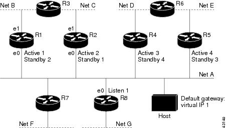
If the host wants to send a packet to another host on Net D, then it first sends it to its default gateway, the virtual IP address of HSRP group 1.
The following is the packet received from the host:
dest MAC         = HSRP group 1 virtual MAC
source MAC       = Host MAC
dest IP          = host-on-netD IP
source IP        = Host IP
Device R1 receives this packet and determines that device R4 can provide a better path to Net D, so it prepares to send a redirect message that will redirect the host to the real IP address of device R4 (because only real IP addresses are in its routing table).
The following is the initial ICMP redirect message sent by device R1:
dest MAC         = Host MAC
source MAC       = router R1 MAC
dest IP          = Host IP
source IP        = router R1 IP
gateway to use   = router R4 IP
Before this redirect occurs, the HSRP process of device R1 determines that device R4 is the active HSRP device for group 3, so it changes the next hop in the redirect message from the real IP address of device R4 to the virtual IP address of group 3. Furthermore, it determines from the destination MAC address of the packet that triggered the redirect message that the host used the virtual IP address of group 1 as its gateway, so it changes the source IP address of the redirect message to the virtual IP address of group 1.
The modified ICMP redirect message showing the two modified fields (*) is as follows:
dest MAC         = Host MAC
source MAC       = router R1 MAC
dest IP          = Host IP
source IP*       = HSRP group 1 virtual IP
gateway to use*  = HSRP group 3 virtual IP
This second modification is necessary because hosts compare the source IP address of the ICMP redirect message with their default gateway. If these addresses do not match, the ICMP redirect message is ignored. The routing table of the host now consists of the default gateway, virtual IP address of group 1, and a route to Net D through the virtual IP address of group 3.
ICMP Redirects to Passive HSRP Devices
ICMP redirects to passive HSRP devices are not permitted. Redundancy may be lost if hosts learn the real IP addresses of HSRP devices.
In the "Network Supporting the HSRP ICMP Redirection Filter" figure, redirection to device R8 is not allowed because R8 is a passive HSRP device. In this case, packets from the host to Net D will first go to device R1 and then be forwarded to device R4; that is, they will traverse the network twice.
A network configuration with passive HSRP devices is considered a misconfiguration. For HSRP ICMP redirection to operate optimally, every device on the network that is running HSRP should contain at least one active HSRP group.
ICMP Redirects to Non-HSRP Devices
ICMP redirects to devices not running HSRP on their local interface are permitted. No redundancy is lost if hosts learn the real IP address of non-HSRP devices.
In the "Network Supporting the HSRP ICMP Redirection Filter" figure, redirection to device R7 is allowed because R7 is not running HSRP. In this case, the next hop IP address is unchanged. The source IP address is changed dependent upon the destination MAC address of the original packet. You can specify the no standby redirect unknown command to stop these redirects from being sent.
Passive HSRP Advertisement Messages
Passive HSRP devices send out HSRP advertisement messages both periodically and when entering or leaving the passive state. Thus, all HSRP devices can determine the HSRP group state of any HSRP device on the network. These advertisements inform other HSRP devices on the network of the HSRP interface state, as follows:
Active—Interface has at least one active group. A single advertisement is sent out when the first group becomes active.
Dormant—Interface has no HSRP groups. A single advertisement is sent once when the last group is removed.
Passive—Interface has at least one nonactive group and no active groups. Advertisements are sent out periodically.
You can adjust the advertisement interval and hold-down time using the standby redirect timers command.
ICMP Redirects Not Sent
If the HSRP device cannot uniquely determine the IP address used by the host when it sends the packet that caused the redirect, the redirect message will not be sent. The device uses the destination MAC address in the original packet to make this determination. In certain configurations, such as the use of the standby use-bia interface configuration command specified on an interface, redirects cannot be sent. In this case, the HSRP groups use the interface MAC address as their virtual MAC address. The device now cannot determine if the default gateway of the host is the real IP address or one of the HSRP virtual IP addresses that are active on the interface.
The IP source address of an ICMP packet must match the gateway address used by the host in the packet that triggered the ICMP packet, otherwise the host will reject the ICMP redirect packet. An HSRP device uses the destination MAC address to determine the gateway IP address of the host. If the HSRP device is using the same MAC address for multiple IP addresses, uniquely determining the gateway IP address of the host is not possible, and the redirect message is not sent.
The following is sample output from the debug standby events icmp EXEC command if HSRP could not uniquely determine the gateway used by the host:
10:43:08: HSRP: ICMP redirect not sent to 10.0.0.4 for dest 10.0.1.2
10:43:08: HSRP: could not uniquely determine IP address for mac 00d0.bbd3.bc22
HSRP Support for MPLS VPNs
HSRP support for a Multiprotocol Label Switching (MPLS) VPN interface is useful when an Ethernet LAN is connected between two provider edge (PE) devices with either of the following conditions:
A customer edge (CE) device with a default route to the HSRP virtual IP address
One or more hosts with the HSRP virtual IP address configured as the default gateway
Each VPN is associated with one or more VPN routing and forwarding (VRF) instances. A VRF consists of the following elements:
IP routing table
Cisco Express Forwarding table
Set of interfaces that use the Cisco Express Forwarding forwarding table
Set of rules and routing protocol parameters to control the information in the routing tables
VPN routing information is stored in the IP routing table and the Cisco Express Forwarding table for each VRF. A separate set of routing and Cisco Express Forwarding tables is maintained for each VRF. These tables prevent information from being forwarded outside a VPN and also prevent packets that are outside a VPN from being forwarded to a device within the VPN.
HSRP adds ARP entries and IP hash table entries (aliases) using the default routing table instance. However, a different routing table instance is used when VRF forwarding is configured on an interface, causing ARP and ICMP echo requests for the HSRP virtual IP address to fail.
HSRP support for MPLS VPNs ensures that the HSRP virtual IP address is added to the correct IP routing table and not to the default routing table.
HSRP Multiple Group Optimization
The configuration of many hundreds of subinterfaces on the same physical interface, with each subinterface having its own HSRP group, can cause the processes of negotiation and maintenance of multiple HSRP groups to have a detrimental impact on network traffic and CPU utilization.
Only one HSRP group is required on a physical interface for the purposes of electing active and standby devices. This group is known as the master group. Other HSRP groups may be created on each subinterface and linked to the master group via the group name. These linked HSRP groups are known as client or slave groups.
The HSRP group state of the client groups follows that of the master group. Client groups do not participate in any sort of device election mechanism.
Client groups send periodic messages in order to refresh their virtual MAC addresses in switches and learning bridges. The refresh message may be sent at a much lower frequency compared with the protocol election messages sent by the master group.
HSRP—ISSU
The In Service Software Upgrade (ISSU) process allows Cisco software to be updated or otherwise modified while packet forwarding continues. In most networks, planned software upgrades are a significant cause of downtime. ISSU allows Cisco software to be modified while packet forwarding continues, which increases network availability and reduces downtime caused by planned software upgrades.
For detailed information about ISSU, see the Cisco IOS In Service Software Upgrade Process document in the High Availability Configuration Guide.
SSO HSRP
SSO HSRP alters the behavior of HSRP when a device with redundant Route Processors (RPs) is configured for stateful switchover (SSO) redundancy mode. When an RP is active and the other RP is standby, SSO enables the standby RP to take over if the active RP fails.
With this functionality, HSRP SSO information is synchronized to the standby RP, allowing traffic that is sent using the HSRP virtual IP address to be continuously forwarded during a switchover without a loss of data or a path change. Additionally, if both RPs fail on the active HSRP device, then the standby HSRP device takes over as the active HSRP device.
The feature is enabled by default when the redundancy mode of operation is set to SSO.
SSO Dual-Route Processors and Cisco Nonstop Forwarding
SSO functions in networking devices (usually edge devices) that support dual RPs. SSO provides RP redundancy by establishing one of the RPs as the active processor and the other RP as the standby processor. SSO also synchronizes critical state information between the RPs so that network state information is dynamically maintained between RPs.
SSO is generally used with Cisco nonstop forwarding (NSF). Cisco NSF enables forwarding of data packets to continue along known routes while the routing protocol information is being restored following a switchover. With NSF, users are less likely to experience service outages.
HSRP and SSO Working Together
The SSO HSRP feature enables the Cisco IOS HSRP subsystem software to detect that a standby RP is installed and the system is configured in SSO redundancy mode. Further, if the active RP fails, no change occurs to the HSRP group itself and traffic continues to be forwarded through the current active gateway device.
Prior to introduction of the SSO HSRP feature, when the primary RP of the active device failed, it would stop participating in the HSRP group and trigger another switch in the group to take over as the active HSRP switch.
SSO HSRP is required to preserve the forwarding path for traffic destined to the HSRP virtual IP address through an RP switchover.
Configuring SSO on the edge device enables the traffic on the Ethernet links to continue during an RP failover without the Ethernet traffic switching over to an HSRP standby device (and then back, if preemption is enabled).
 Note | You may want to disable SSO HSRP by using the no standby sso command if you have LAN segments that should switch HSRP traffic to a redundant device while SSO maintains traffic flow for other connections. |
HSRP BFD Peering
The HSRP BFD Peering feature introduces Bidirectional Forwarding Detection (BFD) in the Hot Standby Router Protocol (HSRP) group member health monitoring system. HSRP supports BFD as a part of the HSRP group member health monitoring system. Without BFD, HSRP runs as a process in a multiprocess system and cannot be guaranteed to be scheduled in time to service large numbers of groups with hello and hold timers, in milliseconds. BFD runs as a pseudopreemptive process and can therefore be guaranteed to run when required. Only one BFD session between two devices can provide early failover notification for multiple HSRP groups.
This feature is enabled by default. The HSRP standby device learns the real IP address of the HSRP active device from the HSRP hello messages. The standby device registers as a BFD client and asks to be notified if the active device becomes unavailable. When BFD determines that the connections between standby and active devices has failed, it will notify HSRP on the standby device which will immediately take over as the active device.
BFD provides a low-overhead, short-duration method of detecting failures in the forwarding path between two adjacent devices, including the interfaces, data links, and forwarding planes. BFD is a detection protocol that you enable at the interface and routing protocol levels. Cisco supports the BFD asynchronous mode, which depends on the sending of BFD control packets between two systems to activate and maintain BFD neighbor sessions between devices. Therefore, to create a BFD session, you must configure BFD on both systems (or BFD peers). When BFD is enabled on the interfaces and at the device level for HSRP, a BFD session is created, BFD timers are negotiated, and the BFD peers will begin to send BFD control packets to each other at the negotiated interval.
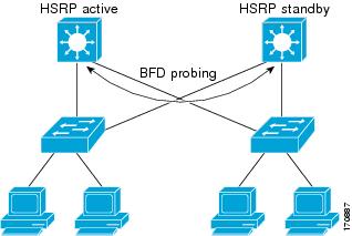
BFD provides fast BFD peer failure detection times independently of all media types, encapsulations, topologies, and routing protocols such as, Border Gateway Protocol (BGP), Enhanced Interior Gateway Routing Protocol (EIGRP), Hot Standby Router Protocol (HSRP), Intermediate System To Intermediate System (IS-IS), and Open Shortest Path First (OSPF). By sending rapid failure detection notices to the routing protocols in the local device to initiate the routing table recalculation process, BFD contributes to greatly reduce overall network convergence time. The figure below shows a simple network with two devices running HSRP and BFD.
For more information about BFD, see the IP Routing: BFD Configuration Guide.
HSRP MIB Traps
HSRP MIB supports Simple Network Management Protocol (SNMP) Get operations, to allow network devices to get reports about HSRP groups in a network from the network management station.
Enabling HSRP MIB trap support is performed through the CLI, and the MIB is used for getting the reports. A trap notifies the network management station when a device leaves or enters the active or standby state. When an entry is configured from the CLI, the RowStatus for that group in the MIB immediately goes to the active state.
Cisco software supports a read-only version of the MIB, and set operations are not supported.
This functionality supports four MIB tables, as follows:
cHsrpGrpEntry table defined in CISCO-HSRP-MIB.my
cHsrpExtIfTrackedEntry, defined in CISCO-HSRP-EXT-MIB.my
cHsrpExtSecAddrEntry, defined in CISCO-HSRP-EXT-MIB.my
cHsrpExtIfEntry defined in CISCO-HSRP-EXT-MIB.my
The cHsrpGrpEntry table consists of all the group information defined in RFC 2281, Cisco Hot Standby Router Protocol; the other tables consist of the Cisco extensions to RFC 2281, which are defined in CISCO-HSRP-EXT-MIB.my.
How to Configure HSRP
- Enabling HSRP
- Delaying the Initialization of HSRP on an Interface
- Configuring HSRP Priority and Preemption
- Configuring HSRP Object Tracking
- Configuring HSRP MD5 Authentication Using a Key String
- Configuring HSRP MD5 Authentication Using a Key Chain
- Troubleshooting HSRP MD5 Authentication
- Configuring HSRP Text Authentication
- Configuring HSRP Timers
- Configuring an HSRP MAC Refresh Interval
- Configuring Multiple HSRP Groups for Load Balancing
- Improving CPU and Network Performance with HSRP Multiple Group Optimization
- Enabling HSRP Support for ICMP Redirect Messages
- Configuring HSRP Virtual MAC Addresses or BIA MAC Addresses
- Linking IP Redundancy Clients to HSRP Groups
- Changing to HSRP Version 2
- Enabling SSO Aware HSRP
- Verifying SSO Aware HSRP
- Enabling HSRP MIB Traps
- Configuring BFD Session Parameters on an Interface
- Configuring HSRP BFD Peering
- Verifying HSRP BFD Peering
Enabling HSRP
Perform this task to enable HSRP.
The standby ip interface configuration command activates HSRP on the configured interface. If an IP address is specified, that address is used as the virtual IP address for the Hot Standby group. For HSRP to elect a designated device, you must configure the virtual IP address for at least one of the devices in the group; it can be learned on the other devices in the group.
You can configure many attributes in HSRP such as authentication, timers, priority, and preemption. You should configure the attributes before enabling the HSRP group. This practice avoids authentication error messages and unexpected state changes in other routers that can occur if the group is enabled first and then there is a long enough delay (one or two hold times) before the other attribues are configured.
We recommend that you always specify an HSRP IP address.
1.
enable
2.
configure
terminal
3.
interface
type
number
4.
ip
address
ip-address
mask
5.
standby [group-number]
ip [ip-address [secondary]]
6.
end
7.
show
standby [all] [brief]
8.
show
standby
type
number [group-number |
all] [brief]
DETAILED STEPS
Delaying the Initialization of HSRP on an Interface
The standby delay command is used to delay HSRP initialization either after a reload and/or after an interface comes up. This configuration allows the interface and device time to settle down after the interface up event and helps prevent HSRP state flapping.
We recommend that you use the standby minimum reload command if the standby timers command is configured in milliseconds or if HSRP is configured on a VLAN interface.
1.
enable
2.
configure
terminal
3.
interface
type
number
4.
ip
address
ip-address
mask
5.
standby
delay
minimum
min-seconds
reload
reload-seconds
6.
standby [group-number ]
ip [ip-address [secondary]]
7.
end
8.
show
standby
delay [typenumber]
DETAILED STEPS
Configuring HSRP Priority and Preemption
1.
enable
2.
configure
terminal
3.
interface
type
number
4.
ip
address
ip-address
mask
5.
standby [group-number]
priority
priority
6.
standby [group-number]
preempt [delay {minimum |
reload |
sync}
seconds]
7.
standby [group-number]
ip
ip-address [secondary]]
8.
end
9.
show
standby [all] [brief]
10.
show
standby
type
number [group-number |
all] [brief]
DETAILED STEPS
| Command or Action | Purpose | |
|---|---|---|
| Step 1 |
enable
Example: Device> enable |
Enables privileged EXEC mode. |
| Step 2 |
configure
terminal
Example: Device# configure terminal |
Enters global configuration mode. |
| Step 3 |
interface
type
number
Example: Device(config)# interface GigabitEthernet0/0/0 |
Configures an interface type and enters interface configuration mode. |
| Step 4 |
ip
address
ip-address
mask
Example: Device(config-if)# ip address 10.0.0.1 255.255.255.0 |
Specifies an IP address for an interface. |
| Step 5 |
standby [group-number]
priority
priority
Example: Device(config-if)# standby 1 priority 110 |
Configures HSRP priority. |
| Step 6 |
standby [group-number]
preempt [delay {minimum |
reload |
sync}
seconds]
Example: Device(config-if)# standby 1 preempt delay minimum 380 |
Configures HSRP preemption and preemption delay. |
| Step 7 |
standby [group-number]
ip
ip-address [secondary]]
Example: Device(config-if)# standby 1 ip 10.0.0.3 255.255.255.0 | Activates HSRP. |
| Step 8 |
end
Example: Device(config-if)# end |
Returns to privileged EXEC mode. |
| Step 9 |
show
standby [all] [brief]
Example: Device# show standby |
(Optional) Displays HSRP information. |
| Step 10 |
show
standby
type
number [group-number |
all] [brief]
Example: Device# show standby GigabitEthernet 0/0/0 |
(Optional) Displays HSRP information about specific groups or interfaces. |
Configuring HSRP Object Tracking
Perform this task to configure HSRP to track an object and change the HSRP priority based on the state of the object.
Each tracked object is identified by a unique number that is specified on the tracking CLI. Client processes use this number to track a specific object.
1.
enable
2.
configure
terminal
3.
track
object-number
interface
type
number {line-protocol |
ip
routing}
4.
exit
5.
interface
type
number
6.
standby [group-number]
track
object-number [decrement
priority-decrement] [shutdown]
7.
standby [group-number]
ip [ip-address [secondary]]
8.
end
9.
show
track [object-number |
brief] [interface [brief] |
ip
route [brief] |
resolution |
timers]
DETAILED STEPS
| Command or Action | Purpose | |||
|---|---|---|---|---|
| Step 1 |
enable
Example: Device> enable |
Enables privileged EXEC mode. | ||
| Step 2 |
configure
terminal
Example: Device# configure terminal |
Enters global configuration mode. | ||
| Step 3 |
track
object-number
interface
type
number {line-protocol |
ip
routing}
Example: Device(config)# track 100 interface GigabitEthernet 0/0/0 line-protocol |
Configures an interface to be tracked and enters tracking configuration mode. | ||
| Step 4 |
exit
Example: Device(config-track)# exit |
Returns to global configuration mode. | ||
| Step 5 |
interface
type
number
Example: Device(config)# interface GigabitEthernet 0/0/0 |
Configures an interface type and enters interface configuration mode. | ||
| Step 6 |
standby [group-number]
track
object-number [decrement
priority-decrement] [shutdown]
Example: Device(config-if)# standby 1 track 100 decrement 20 |
Configures HSRP to track an object and change the Hot Standby priority on the basis of the state of the object.
| ||
| Step 7 |
standby [group-number]
ip [ip-address [secondary]]
Example: Device(config-if)# standby 1 ip 10.10.10.0 | | ||
| Step 8 |
end
Example: Device(config-if)# end |
Returns to privileged EXEC mode. | ||
| Step 9 |
show
track [object-number |
brief] [interface [brief] |
ip
route [brief] |
resolution |
timers]
Example: Device# show track 100 interface |
Displays tracking information. |
Configuring HSRP MD5 Authentication Using a Key String
Note | Text authentication cannot be combined with MD5 authentication for an HSRP group at any one time. When MD5 authentication is configured, the text authentication field in HSRP hello messages is set to all zeroes on transmit and ignored on receipt, provided the receiving device also has MD5 authentication enabled. |
Note | If you are changing a key string in a group of devices, change the active device last to prevent any HSRP state change. The active device should have its key string changed no later than one hold-time period, specified by the standy timers interface configuration command, after the nonactive devices. This procedure ensures that the nonactive devices do not time out the active device. |
1.
enable
2.
configure
terminal
3.
terminal
interface
type
number
4.
ip
address
ip-address
mask [secondary]
5.
standby [group-number]
priority
priority
6.
standby [group-number]
preempt [delay {minimum |
reload |
sync}
seconds]
7.
standby [group-number]
authentication
md5
key-string [0 |
7]
key [timeout
seconds]
8.
standby [group-number]
ip [ip-address] [secondary]]
9. Repeat Steps 1 through 8 on each device that will communicate.
10.
end
11.
show
standby
DETAILED STEPS
| Command or Action | Purpose | |
|---|---|---|
| Step 1 |
enable
Example: Device> enable |
Enables privileged EXEC mode. |
| Step 2 |
configure
terminal
Example: Device# configure terminal |
Enters global configuration mode. |
| Step 3 |
terminal
interface
type
number
Example: Device(config)# interface GigabitEthernet 0/0/0 |
Configures an interface type and enters interface configuration mode. |
| Step 4 |
ip
address
ip-address
mask [secondary]
Example: Device(config-if)# ip address 10.0.0.1 255.255.255.0 |
Specifies a primary or secondary IP address for an interface. |
| Step 5 |
standby [group-number]
priority
priority
Example: Device(config-if)# standby 1 priority 110 |
Configures HSRP priority. |
| Step 6 |
standby [group-number]
preempt [delay {minimum |
reload |
sync}
seconds]
Example: Device(config-if)# standby 1 preempt |
Configures HSRP preemption. |
| Step 7 |
standby [group-number]
authentication
md5
key-string [0 |
7]
key [timeout
seconds]
Example: Device(config-if)# standby 1 authentication md5 key-string d00b4r987654321a timeout 30 |
Configures an authentication string for HSRP MD5 authentication.
|
| Step 8 |
standby [group-number]
ip [ip-address] [secondary]]
Example: Device(config-if)# standby 1 ip 10.0.0.3 |
Activates HSRP. |
| Step 9 | Repeat Steps 1 through 8 on each device that will communicate. |
— |
| Step 10 |
end
Example: Device(config-if)# end |
Returns to privileged EXEC mode. |
| Step 11 |
show
standby
Example: Device# show standby |
(Optional) Displays HSRP information. |
Configuring HSRP MD5 Authentication Using a Key Chain
Perform this task to configure HSRP MD5 authentication using a key chain. Key chains allow a different key string to be used at different times according to the key chain configuration. HSRP will query the appropriate key chain to obtain the current live key and key ID for the specified key chain.
1.
enable
2.
configure
terminal
3.
key
chain
name-of-chain
4.
key
key-id
5.
key-string
string
6.
exit
7.
exit
8.
interface
type
number
9.
ip
address
ip-address
mask [secondary]
10.
standby [group-number]
priority
priority
11.
standby [group-number]
preempt [delay {minimum |
reload |
sync}
seconds]
12.
standby [group-number]
authentication
md5
key-chain
key-chain-name
13.
standby [group-number]
ip [ip-address [secondary]]
14. Repeat Steps 1 through 12 on each device that will communicate.
15.
end
16.
show
standby
DETAILED STEPS
| Command or Action | Purpose | |
|---|---|---|
| Step 1 |
enable
Example: Device> enable |
Enables privileged EXEC mode. |
| Step 2 |
configure
terminal
Example: Device# configure terminal |
Enters global configuration mode. |
| Step 3 |
key
chain
name-of-chain
Example: Device(config)# key chain hsrp1 |
Enables authentication for routing protocols, identifies a group of authentication keys, and enters key-chain configuration mode. |
| Step 4 |
key
key-id
Example: Device(config-keychain)# key 100 |
Identifies an authentication key on a key chain and enters key-chain key configuration mode. |
| Step 5 |
key-string
string
Example: Device(config-keychain-key)# key-string mno172 |
Specifies the authentication string for a key. |
| Step 6 |
exit
Example: Device(config-keychain-key)# exit |
Returns to key-chain configuration mode. |
| Step 7 |
exit
Example: Device(config-keychain)# exit |
Returns to global configuration mode. |
| Step 8 |
interface
type
number
Example: Device(config)# interface GigabitEthernet 0/0/0 |
Configures an interface type and enters interface configuration mode. |
| Step 9 |
ip
address
ip-address
mask [secondary]
Example: Device(config-if)# ip address 10.21.8.32 255.255.255.0 |
Specifies a primary or secondary IP address for an interface. |
| Step 10 |
standby [group-number]
priority
priority
Example: Device(config-if)# standby 1 priority 110 |
Configures HSRP priority. |
| Step 11 |
standby [group-number]
preempt [delay {minimum |
reload |
sync}
seconds]
Example: Device(config-if)# standby 1 preempt |
Configures HSRP preemption. |
| Step 12 |
standby [group-number]
authentication
md5
key-chain
key-chain-name
Example: Device(config-if)# standby 1 authentication md5 key-chain hsrp1 |
Configures an authentication MD5 key chain for HSRP MD5 authentication. |
| Step 13 |
standby [group-number]
ip [ip-address [secondary]]
Example: Device(config-if)# standby 1 ip 10.21.8.12 |
Activates HSRP. |
| Step 14 | Repeat Steps 1 through 12 on each device that will communicate. |
— |
| Step 15 |
end
Example: Device(config-if)# end |
Returns to privileged EXEC mode. |
| Step 16 |
show
standby
Example: Device# show standby |
(Optional) Displays HSRP information. |
Troubleshooting HSRP MD5 Authentication
Perform this task if HSRP MD5 authentication is not operating correctly.
1.
enable
2.
debug
standby
errors
DETAILED STEPS
| Command or Action | Purpose |
|---|
Examples
In the following example, Device A has MD5 text string authentication configured, but Device B has the default text authentication:
Device# debug standby errors

A:Jun 16 12:14:50.337:HSRP:Et0/1 Grp 0 Auth failed for Hello pkt from 10.21.0.5, MD5 confgd but no tlv
B:Jun 16 12:16:34.287:HSRP:Et0/1 Grp 0 Auth failed for Hello pkt from 10.21.0.4, Text auth failed
In the following example, both Device A and Device B have different MD5 authentication strings:
Device# debug standby errors

A:Jun 16 12:19:26.335:HSRP:Et0/1 Grp 0 Auth failed for Hello pkt from 10.21.0.5, MD5 auth failed
B:Jun 16 12:18:46.280:HSRP:Et0/1 Grp 0 Auth failed for Hello pkt from 10.21.0.4, MD5 auth failed
Configuring HSRP Text Authentication
1.
enable
2.
configure
terminal
3.
interface
type
number
4.
ip
address
ip-address
mask [secondary]
5.
standby [group-number]
priority
priority
6.
standby [group-number]
preempt [delay {minimum |
reload |
sync}
seconds]
7.
standby [group-number]
authentication
text
string
8.
standby [group-number]
ip [ip-address [secondary]]
9. Repeat Steps 1 through 8 on each device that will communicate.
10.
end
11.
show
standby
DETAILED STEPS
| Command or Action | Purpose | |
|---|---|---|
| Step 1 |
enable
Example: Device> enable |
Enables privileged EXEC mode. |
| Step 2 |
configure
terminal
Example: Device# configure terminal |
Enters global configuration mode. |
| Step 3 |
interface
type
number
Example: Device(config)# interface GigabitEthernet 0/0/0 |
Configures an interface type and enters interface configuration mode. |
| Step 4 |
ip
address
ip-address
mask [secondary]
Example: Device(config-if)# ip address 10.0.0.1 255.255.255.0 |
Specifies a primary or secondary IP address for an interface. |
| Step 5 |
standby [group-number]
priority
priority
Example: Device(config-if)# standby 1 priority 110 |
Configures HSRP priority. |
| Step 6 |
standby [group-number]
preempt [delay {minimum |
reload |
sync}
seconds]
Example: Device(config-if)# standby 1 preempt |
Configures HSRP preemption. |
| Step 7 |
standby [group-number]
authentication
text
string
Example: Device(config-if)# standby 1 authentication text authentication1 |
Configures an authentication string for HSRP text authentication. |
| Step 8 |
standby [group-number]
ip [ip-address [secondary]]
Example: Device(config-if)# standby 1 ip 10.0.0.3 |
Activates HSRP. |
| Step 9 | Repeat Steps 1 through 8 on each device that will communicate. |
-- |
| Step 10 |
end
Example: Device(config-if)# end |
Returns to privileged EXEC mode. |
| Step 11 |
show
standby
Example: Device# show standby |
(Optional) Displays HSRP information. |
Configuring HSRP Timers
Note | We recommend configuring a minimum hello-time value of 250 milliseconds and a minimum hold-time value of 800 milliseconds. |
1.
enable
2.
configure
terminal
3.
interface
type
number
4.
ip
address
ip-address
mask [secondary]]
5.
standby [group-number]
timers [msec]
hellotime [msec]
holdtime
6.
standby [group-number]
ip [ip-address [secondary]]
DETAILED STEPS
| Command or Action | Purpose | |
|---|---|---|
| Step 1 |
enable
Example: Device> enable |
Enables privileged EXEC mode. |
| Step 2 |
configure
terminal
Example: Device# configure terminal |
Enters global configuration mode. |
| Step 3 |
interface
type
number
Example: Device(config)# interface Gigabit Ethernet 0/0/1 |
Configures an interface type and enters interface configuration mode. |
| Step 4 |
ip
address
ip-address
mask [secondary]]
Example: Device(config-if)# ip address 10.0.0.1 255.255.255.0 |
Specifies a primary or secondary IP address for an interface. |
| Step 5 |
standby [group-number]
timers [msec]
hellotime [msec]
holdtime
Example: Device(config-if)# standby 1 timers 5 15 |
Configures the time between hello packets and the time before other devices declare the active Hot Standby or standby device to be down. |
| Step 6 |
standby [group-number]
ip [ip-address [secondary]]
Example: Device(config-if)# standby 1 ip 10.0.0.3 |
Activates HSRP. |
Configuring an HSRP MAC Refresh Interval
1.
enable
2.
configure
terminal
3.
interface
type
number
4.
ip
address
ip-address
mask [secondary]
5.
standby
mac-refresh
seconds
6.
standby [group-number]
ip [ip-address [secondary]]
DETAILED STEPS
| Command or Action | Purpose | |
|---|---|---|
| Step 1 |
enable
Example: Device> enable |
Enables privileged EXEC mode. |
| Step 2 |
configure
terminal
Example: Device# configure terminal |
Enters global configuration mode. |
| Step 3 |
interface
type
number
Example: Device(config)# interface GigabitEthernet 0/0/1 |
Configures an interface type and enters interface configuration mode. |
| Step 4 |
ip
address
ip-address
mask [secondary]
Example: Device(config-if)# ip address 10.0.0.1 255.255.255.0 |
Specifies a primary or secondary IP address for an interface. |
| Step 5 |
standby
mac-refresh
seconds
Example: Device(config-if)# standby mac-refresh 100 |
Changes the interval at which packets are sent to refresh the MAC cache when HSRP is running over FDDI. |
| Step 6 |
standby [group-number]
ip [ip-address [secondary]]
Example: Device(config-if)# standby 1 ip 10.0.0.3 |
Activates HSRP. |
Configuring Multiple HSRP Groups for Load Balancing
Perform this task to configure multiple HSRP groups for load balancing.
Multiple HSRP groups enable redundancy and load-sharing within networks and allow redundant devices to be more fully utilized. A device actively forwarding traffic for one HSRP group can be in standby or in the listen state for another group.
If two devices are used, then Device A would be configured as active for group 1 and standby for group 2. Device B would be standby for group 1 and active for group 2. Fifty percent of the hosts on the LAN would be configured with the virtual IP address of group 1 and the remaining hosts would be configured with the virtual IP address of group 2. See the Example: Multiple HSRP for Load Balancing section for a diagram and configuration example.
1.
enable
2.
configure
terminal
3.
interface
type
number
4.
ip
address
ip-address
mask [secondary]
5.
standby [group-number]
priority
priority
6.
standby [group-number]
preempt [delay {minimum |
reload |
sync}
delay]
7.
standby [group-number]
ip [ip-address]
secondary]
8. On the same device, repeat Steps 5 through 7 to configure the device attributes for different standby groups.
9.
exit
10. Repeat Steps 3 through 9 on another device.
DETAILED STEPS
| Command or Action | Purpose | |
|---|---|---|
| Step 1 |
enable
Example: Device> enable |
Enables privileged EXEC mode. |
| Step 2 |
configure
terminal
Example: Device# configure terminal |
Enters global configuration mode. |
| Step 3 |
interface
type
number
Example: Device(config)# interface GigabitEthernet 0/0/0 |
Configures an interface type and enters interface configuration mode. |
| Step 4 |
ip
address
ip-address
mask [secondary]
Example: Device(config-if)# ip address 10.0.0.1 255.255.255.0 |
Specifies a primary or secondary IP address for an interface. |
| Step 5 |
standby [group-number]
priority
priority
Example: Device(config-if)# standby 1 priority 110 |
Configures HSRP priority. |
| Step 6 |
standby [group-number]
preempt [delay {minimum |
reload |
sync}
delay]
Example: Device(config-if)# standby 1 preempt |
Configures HSRP preemption. |
| Step 7 |
standby [group-number]
ip [ip-address]
secondary]
Example: Device(config-if)# standby 1 ip 10.0.0.3 |
Activates HSRP. |
| Step 8 | On the same device, repeat Steps 5 through 7 to configure the device attributes for different standby groups. |
For example, Device A can be configured as an active device for group 1 and be configured as an active or standby device for another HSRP group with different priority and preemption values. |
| Step 9 |
exit
Example: Device(config-if)# exit |
Exits to global configuration mode. |
| Step 10 | Repeat Steps 3 through 9 on another device. |
Configures multiple HSRP and enables load balancing on another device. |
Improving CPU and Network Performance with HSRP Multiple Group Optimization
Perform this task to configure multiple HSRP client groups.
The standby follow command configures an HSRP group to become a slave of another HSRP group.
HSRP client groups follow the master HSRP with a slight, random delay so that all client groups do not change at the same time.
Use the standby mac-refresh seconds command to directly change the HSRP client group refresh interval. The default interval is 10 seconds and can be configured to as much as 255 seconds.
Note |
Device(config-if)# standby 1 priority 110
%Warning: This setting has no effect while following another group.
Device(config-if)# standby 1 timers 5 15
    % Warning: This setting has no effect while following another group.
Device(config-if)# standby 1 preempt delay minimum 300
    % Warning: This setting has no effect while following another group.
|
Configure the HSRP master group using the steps in the Configuring Multiple HSRP Groups for Load Balancing section.
1.
enable
2.
configure
terminal
3.
interface
type
number
4.
ip
address
ip-address
mask [secondary]
5.
standby
mac-refresh
seconds
6.
standby
group-number
follow
group-name
7.
exit
8. Repeat Steps 3 through 6 to configure additional HSRP client groups.
DETAILED STEPS
| Command or Action | Purpose | |
|---|---|---|
| Step 1 |
enable
Example: Device> enable |
Enables privileged EXEC mode. |
| Step 2 |
configure
terminal
Example: Device# configure terminal |
Enters global configuration mode. |
| Step 3 |
interface
type
number
Example: Device(config)# interface GigabitEthernet 0/0/0 |
Configures an interface type and enters interface configuration mode. |
| Step 4 |
ip
address
ip-address
mask [secondary]
Example: Device(config-if)# ip address 10.0.0.1 255.255.255.0 |
Specifies a primary or secondary IP address for an interface. |
| Step 5 |
standby
mac-refresh
seconds
Example: Device(config-if)# standby mac-refresh 30 |
Configures the HSRP client group refresh interval. |
| Step 6 |
standby
group-number
follow
group-name
Example: Device(config-if)# standby 1 follow HSRP1 |
Configures an HSRP group as a client group. |
| Step 7 |
exit
Example: Device(config-if)# exit |
Exits to global configuration mode. |
| Step 8 | Repeat Steps 3 through 6 to configure additional HSRP client groups. |
Configures multiple HSRP client groups. |
Enabling HSRP Support for ICMP Redirect Messages
By default, HSRP filtering of ICMP redirect messages is enabled on devices running HSRP. Perform this task to reenable this feature on your device if it is disabled.
1.
enable
2.
configure
terminal
3.
interface
type
number
4.
standby
redirect [timers
advertisement
holddown] [unknown]
5.
end
6.
show
standby
redirect [ip-address] [interface-type
interface-number] [active] [passive] [timers]
DETAILED STEPS
| Command or Action | Purpose | |
|---|---|---|
| Step 1 |
enable
Example: Device> enable |
Enables privileged EXEC mode. |
| Step 2 |
configure
terminal
Example: Device# configure terminal |
Enters global configuration mode. |
| Step 3 |
interface
type
number
Example: Device(config)# interface GigabitEthernet 0/0/0 |
Configures an interface type and enters interface configuration mode. |
| Step 4 |
standby
redirect [timers
advertisement
holddown] [unknown]
Example: Device(config-if)# standby redirect |
Enables HSRP filtering of ICMP redirect messages. |
| Step 5 |
end
Example: Device(config-if)# end |
Returns to privileged EXEC mode. |
| Step 6 |
show
standby
redirect [ip-address] [interface-type
interface-number] [active] [passive] [timers]
Example: Device# show standby redirect |
(Optional) Displays ICMP redirect information on interfaces configured with HSRP. |
Configuring HSRP Virtual MAC Addresses or BIA MAC Addresses
Note | You cannot use the standby use-bia and standby mac-address commands in the same configuration; they are mutually exclusive. The standby use-bia command has the following disadvantages:
|
1.
enable
2.
configure
terminal
3.
interface
type
number
4.
ip
address
ip-address
mask [secondary]
5.
Enter one of the following commands:
6.
standby [group-number]
ip [ip-address [secondary]]
DETAILED STEPS
| Command or Action | Purpose | |
|---|---|---|
| Step 1 |
enable
Example: Device> enable |
Enables privileged EXEC mode. |
| Step 2 |
configure
terminal
Example: Device# configure terminal |
Enters global configuration mode. |
| Step 3 |
interface
type
number
Example: Device(config)# interface GigabitEthernet 0/0/0 |
Configures an interface type and enters interface configuration mode. |
| Step 4 |
ip
address
ip-address
mask [secondary]
Example: Device(config-if)# ip address 172.16.6.5 255.255.255.0 | Configures an IP address for an interface. |
| Step 5 | Enter one of the following commands:
Example: Device(config-if)# standby 1 mac-address 5000.1000.1060 Example: Device(config-if)# standby use-bia |
Specifies a virtual MAC address for HSRP. or Configures HSRP to use the burned-in address of the interface as its virtual MAC address. |
| Step 6 |
standby [group-number]
ip [ip-address [secondary]]
Example: Device(config-if)# standby 1 ip 172.16.6.100 | Activates HSRP. |
Linking IP Redundancy Clients to HSRP Groups
Within the client application, you must first specify the same name as configured in the standby name command.
1.
enable
2.
configure
terminal
3.
interface
type
number
4.
ip
address
ip-address
mask
5.
standby [group-number]
name [redundancy-name]
6.
standby [group-number]
ip [ip-address [secondary]]
DETAILED STEPS
| Command or Action | Purpose | |
|---|---|---|
| Step 1 |
enable
Example: Device> enable |
Enables privileged EXEC mode. |
| Step 2 |
configure
terminal
Example: Device# configure terminal |
Enters global configuration mode. |
| Step 3 |
interface
type
number
Example: Device(config)# interface Ethernet 0/1 |
Configures an interface type and enters interface configuration mode. |
| Step 4 |
ip
address
ip-address
mask
Example: Device(config-if)# ip address 10.0.0.1 255.255.255.0 |
Specifies an IP address for an interface. |
| Step 5 |
standby [group-number]
name [redundancy-name]
Example: Device(config-if)# standby 1 name HSRP-1 |
Configures the name of the standby group. |
| Step 6 |
standby [group-number]
ip [ip-address [secondary]]
Example: Device(config-if)# standby 1 ip 10.0.0.11 | Activates HSRP. |
Changing to HSRP Version 2
HSRP version 2 was introduced to prepare for further enhancements and to expand the capabilities beyond what is possible with HSRP version 1. HSRP version 2 has a different packet format than HSRP version 1.
Note |
|
1.
enable
2.
configure
terminal
3.
interface
type
number
4.
ip
address
ip-address
mask
5.
standby
version {1 |
2}
6.
standby [group-number]
ip [ip-address [secondary]]
7.
end
8.
show
standby
DETAILED STEPS
| Command or Action | Purpose | |
|---|---|---|
| Step 1 |
enable
Example: Device> enable |
Enables privileged EXEC mode. |
| Step 2 |
configure
terminal
Example: Device# configure terminal |
Enters global configuration mode. |
| Step 3 |
interface
type
number
Example: Device(config)# interface vlan 400 |
Configures an interface type and enters interface configuration mode. |
| Step 4 |
ip
address
ip-address
mask
Example: Device(config-if)# ip address 10.10.28.1 255.255.255.0 |
Sets an IP address for an interface. |
| Step 5 |
standby
version {1 |
2}
Example: Device(config-if)# standby version 2 |
Changes the HSRP version. |
| Step 6 |
standby [group-number]
ip [ip-address [secondary]]
Example: Device(config-if)# standby 400 ip 10.10.28.5 |
Activates HSRP. |
| Step 7 |
end
Example: Device(config-if)# end |
Ends the current configuration session and returns to privileged EXEC mode. |
| Step 8 |
show
standby
Example: Device# show standby |
(Optional) Displays HSRP information. |
Enabling SSO Aware HSRP
The SSO aware HSRP is enabled by default when the redundancy mode is set to SSO. Perform this task to reenable HSRP to be SSO aware if it has been disabled.
Note | You may want to disable SSO HSRP by using the no standby sso command if you have LAN segments that should switch HSRP traffic to a redundant device while SSO maintains traffic flow for other connections. |
1.
enable
2.
configure
terminal
3.
redundancy
4.
mode
sso
5.
exit
6.
no
standby
sso
7.
standby
sso
8.
end
DETAILED STEPS
| Command or Action | Purpose | |
|---|---|---|
| Step 1 |
enable
Example: Device> enable |
Enables privileged EXEC mode. |
| Step 2 |
configure
terminal
Example: Device# configure terminal |
Enters global configuration mode. |
| Step 3 |
redundancy
Example: Device(config)# redundancy |
Enters redundancy configuration mode. |
| Step 4 |
mode
sso
Example: Device(config-red)# mode sso |
Enables the redundancy mode of operation to SSO. |
| Step 5 |
exit
Example: Device(config-red)# exit |
Exits redundancy configuration mode. |
| Step 6 |
no
standby
sso
Example: Device(config)# no standby sso |
Disables HSRP SSO mode for all HSRP groups. |
| Step 7 |
standby
sso
Example: Device(config)# standby sso |
Enables the SSO HSRP feature if you have disabled the functionality. |
| Step 8 |
end
Example: Device(config)# end |
Ends the current configuration session and returns to privileged EXEC mode. |
Verifying SSO Aware HSRP
To verify or debug HSRP SSO operation, perform the following steps from the active RP console.
1.
show
standby
2.
debug
standby
events
ha
DETAILED STEPS
| Step 1 |
show
standby
Use the show standby command to display the state of the standby RP, for example: Example: Device# show standby GigabitEthernet0/0/0 - Group 1 State is Active (standby RP) Virtual IP address is 10.1.0.7 Active virtual MAC address is unknown Local virtual MAC address is 000a.f3fd.5001 (bia) Hello time 1 sec, hold time 3 sec Authentication text “authword” Preemption enabled Active router is unknown Standby router is unknown Priority 110 (configured 120) Track object 1 state Down decrement 10 Group name is “name1” (cfgd) |
| Step 2 |
debug
standby
events
ha
Use thedebug standby events ha command to display the active and standby RPs, for example: Example: Device# debug standby events ha !Active RP *Apr 27 04:13:47.755: HSRP: Gi0/0/1 Grp 101 RF Encode state Listen into sync buffer *Apr 27 04:13:47.855: HSRP: CF Sync send ok *Apr 27 04:13:57.755: HSRP: Gi0/0/1 Grp 101 RF Encode state Speak into sync buffer *Apr 27 04:13:57.855: HSRP: CF Sync send ok *Apr 27 04:14:07.755: HSRP: Gi0/0/1 Grp 101 RF Encode state Standby into sync buffer *Apr 27 04:14:07.755: HSRP: Gi0/0/1 Grp 101 RF Encode state Active into sync buffer *Apr 27 04:14:07.863: HSRP: CF Sync send ok *Apr 27 04:14:07.867: HSRP: CF Sync send ok !Standby RP *Apr 27 04:11:21.011: HSRP: RF CF client 32, entity 0 got msg len 24 *Apr 27 04:11:21.011: HSRP: Gi0/0/1 Grp 101 RF sync state Init -> Listen *Apr 27 04:11:31.011: HSRP: RF CF client 32, entity 0 got msg len 24 *Apr 27 04:11:31.011: HSRP: Gi0/0/1 Grp 101 RF sync state Listen -> Speak *Apr 27 04:11:41.071: HSRP: RF CF client 32, entity 0 got msg len 24 *Apr 27 04:11:41.071: HSRP: RF CF client 32, entity 0 got msg len 24 *Apr 27 04:11:41.071: HSRP: Gi0/0/1 Grp 101 RF sync state Speak -> Standby *Apr 27 04:11:41.071: HSRP: Gi0/0/1 Grp 101 RF sync state Standby -> Active |
Enabling HSRP MIB Traps
1.
enable
2.
configure
terminal
3.
snmp-server
enable
traps
hsrp
4.
snmp-server
host
host
community-string
hsrp
DETAILED STEPS
| Command or Action | Purpose | |
|---|---|---|
| Step 1 |
enable
Example: Device> enable |
Enables privileged EXEC mode. |
| Step 2 |
configure
terminal
Example: Device# configure terminal |
Enters global configuration mode. |
| Step 3 |
snmp-server
enable
traps
hsrp
Example: Device(config)# snmp-server enable traps hsrp |
Enables the device to send SNMP traps and informs, and HSRP notifications. |
| Step 4 |
snmp-server
host
host
community-string
hsrp
Example: Device(config)# snmp-server host myhost.comp.com public hsrp |
Specifies the recipient of an SNMP notification operation, and that HSRP notifications be sent to the host. |
Configuring BFD Session Parameters on an Interface
Perform this task to configure Bidirectional Forwarding Detection (BFD) on an interface by setting the baseline BFD session parameters on the interface. Repeat the steps in this task for each interface on which you want to run BFD sessions to BFD neighbors.
1.
enable
2.
configure
terminal
3.
interface
type
number
4.
bfd
interval
milliseconds
min_rx
milliseconds
multiplier
interval-multiplier
5.
end
DETAILED STEPS
| Command or Action | Purpose | |
|---|---|---|
| Step 1 |
enable
Example: Device> enable |
Enables privileged EXEC mode. |
| Step 2 |
configure
terminal
Example: Device# configure terminal |
Enters global configuration mode. |
| Step 3 |
interface
type
number
Example: Device(config)# interface FastEthernet 6/0 |
Enters interface configuration mode. |
| Step 4 |
bfd
interval
milliseconds
min_rx
milliseconds
multiplier
interval-multiplier
Example: Device(config-if)# bfd interval 50 min_rx 50 multiplier 5 |
Enables BFD on the interface. |
| Step 5 |
end
Example: Device(config-if)# end |
Exits interface configuration mode. |
Configuring HSRP BFD Peering
Perform this task to enable Hot Standby Router Protocol (HSRP) Bidirectional Forwarding Detection (BFD) peering. Repeat the steps in this task for each interface over which you want to run BFD sessions to HSRP peers.
HSRP supports BFD peering by default. If HSRP BFD peering is disabled, you can reenable it at the device level to enable BFD support globally for all interfaces or you can reenable it on a per-interface basis at the interface level.
Before you proceed with this task:
1.
enable
2.
configure
terminal
3.
ip
cef
[distributed]
4.
interface
type
number
5.
ip
address
ip-address
mask
6.
standby
[group-number]
ip [ip-address [secondary]]
7.
standby
bfd
8.
exit
9.
standby
bfd
all-interfaces
10.
exit
11.
show
standby
[neighbors]
DETAILED STEPS
| Command or Action | Purpose | |
|---|---|---|
| Step 1 |
enable
Example: Device> enable |
Enables privileged EXEC mode. |
| Step 2 |
configure
terminal
Example: Device# configure terminal |
Enters global configuration mode. |
| Step 3 |
ip
cef
[distributed]
Example: Device(config)# ip cef |
Enables Cisco Express Forwarding or distributed Cisco Express Forwarding. |
| Step 4 |
interface
type
number
Example: Device(config)# interface FastEthernet 6/0 |
Enters interface configuration mode. |
| Step 5 |
ip
address
ip-address
mask
Example: Device(config-if)# ip address 10.0.0.11 255.255.255.0 |
Configures an IP address for the interface. |
| Step 6 |
standby
[group-number]
ip [ip-address [secondary]]
Example: Device(config-if)# standby 1 ip 10.0.0.11 |
Activates HSRP. |
| Step 7 |
standby
bfd
Example: Device(config-if)# standby bfd |
(Optional) Enables HSRP support for BFD on the interface. |
| Step 8 |
exit
Example: Device(config-if)# exit |
Exits interface configuration mode. |
| Step 9 |
standby
bfd
all-interfaces
Example: Device(config)# standby bfd all-interfaces |
(Optional) Enables HSRP support for BFD on all interfaces. |
| Step 10 |
exit
Example: Device(config)# exit |
Exits global configuration mode. |
| Step 11 |
show
standby
[neighbors]
Example: Device# show standby neighbors |
(Optional) Displays information about HSRP support for BFD. |
Verifying HSRP BFD Peering
To verify Hot Standby Router Protocol (HSRP) Bidirectional Forwarding Detection (BFD) peering, use any of the following optional commands.
1.
show
standby
2.
show
standby brief
3.
show
standby
neighbors
[type
number]
4.
show
bfd
neighbors
5.
show
bfd
neighbors
details
DETAILED STEPS
| Step 1 |
show
standby
Use the show standby command to display HSRP information. Example:
Device# show standby

FastEthernet2/0 - Group 1
  State is Active
    2 state changes, last state change 00:08:06
  Virtual IP address is 10.0.0.11
  Active virtual MAC address is 0000.0c07.ac01
    Local virtual MAC address is 0000.0c07.ac01 (v1 default)
  Hello time 3 sec, hold time 10 sec
    Next hello sent in 2.772 secs
  Preemption enabled
  Active router is local
  Standby router is 10.0.0.2, priority 90 (expires in 8.268 sec)
    BFD enabled !
  Priority 110 (configured 110)
    Group name is "hsrp-Fa2/0-1" (default)
|
| Step 2 |
show
standby brief
Use the show standby brief command to display HSRP standby device information in brief. Example: Device# show standby brief Interface Grp Pri P State Active Standby Virtual IP Et0/0 4 120 P Active local 172.24.1.2 172.24.1.254 Et1/0 6 120 P Active local FE80::A8BB:CCFF:FE00:3401 FE80::5:73FF:FEA0:6 |
| Step 3 |
show
standby
neighbors
[type
number]
Use the show standby neighbors command to display information about HSRP peer devices on an interface. Example:
Device1# show standby neighbors

HSRP neighbors on FastEthernet2/0
    10.1.0.22
    No active groups
    Standby groups: 1
    BFD enabled !

Device2# show standby neighbors

HSRP neighbors on FastEthernet2/0
    10.0.0.2
    Active groups: 1
    No standby groups
    BFD enabled !
|
| Step 4 |
show
bfd
neighbors
Use the show bfd neighbors command to display a line-by-line listing of existing Bidirectional Forwarding Detection (BFD) adjacencies. Example: Device# show bfd neighbors IPv6 Sessions NeighAddr LD/RD RH/RS State Int FE80::A8BB:CCFF:FE00:3401 4/3 Up Up Et1/0 FE80::A8BB:CCFF:FE00:3401 4/3 Up Up Et1/0 |
| Step 5 |
show
bfd
neighbors
details
Use the details keyword to display BFD protocol parameters and timers for each neighbor. Example: Device# show bfd neighbors details
OurAddr NeighAddr LD/RD RH/RS Holdown(mult) State Int
10.0.0.2 10.0.0.1 5/0 Down 0 (0 ) Down Fa2/0
Local Diag: 0, Demand mode: 0, Poll bit: 0
MinTxInt: 1000000, MinRxInt: 1000000, Multiplier: 3
Received MinRxInt: 0, Received Multiplier: 0
Holdown (hits): 0(0), Hello (hits): 1000(55)
Rx Count: 0, Rx Interval (ms) min/max/avg: 0/0/0 last: 3314120 ms ago
Tx Count: 55, Tx Interval (ms) min/max/avg: 760/1000/872 last: 412 ms ago
Registered protocols: HSRP !
Last packet: Version: 1 - Diagnostic: 0
State bit: AdminDown - Demand bit: 0
Poll bit: 0 - Final bit: 0
Multiplier: 0 - Length: 0
My Discr.: 0 - Your Discr.: 0
Min tx interval: 0 - Min rx interval: 0
Min Echo interval: 0
|
Configuration Examples for HSRP
- Example: Configuring HSRP Priority and Preemption
- Example: Configuring HSRP Object Tracking
- Example: Configuring HSRP Group Shutdown
- Example: Configuring HSRP MD5 Authentication Using Key Strings
- Example: Configuring HSRP MD5 Authentication Using Key Chains
- Example: Configuring HSRP MD5 Authentication Using Key Strings and Key Chains
- Example: Configuring HSRP Text Authentication
- Example: Configuring Multiple HSRP Groups for Load Balancing
- Example: Improving CPU and Network Performance with HSRP Multiple Group Optimization
- Example: Configuring HSRP Support for ICMP Redirect Messages
- Example: Configuring HSRP Virtual MAC Addresses and BIA MAC Address
- Example: Linking IP Redundancy Clients to HSRP Groups
- Example: Configuring HSRP Version 2
- Example: Enabling SSO-Aware HSRP
- Example: Enabling HSRP MIB Traps
- Example: HSRP BFD Peering
Example: Configuring HSRP Priority and Preemption
In the following example, Device A is configured to be the active device for group 1 because it has the higher priority and standby device for group 2. Device B is configured to be the active device for group 2 and standby device for group 1.
Device A Configuration
Device(config)# interface GigabitEthernet 0/0/0
Device(config-if)# ip address 10.1.0.21 255.255.0.0
Device(config-if)# standby 1 priority 110
Device(config-if)# standby 1 preempt
Device(config-if)# standby 1 ip 10.1.0.1
Device(config-if)# standby 2 priority 95
Device(config-if)# standby 2 preempt
Device(config-if)# standby 2 ip 10.1.0.2
Device B Configuration
Device(config)# interface GigabitEthernet 0/0/0
Device(config-if)# ip address 10.1.0.22 255.255.0.0
Device(config-if)# standby 1 preempt
Device(config-if)# standby 1 priority 105
Device(config-if)# standby 1 ip 10.1.0.1
Device(config-if)# standby 2 priority 110
Device(config-if)# standby 2 preempt
Device(config-if)# standby 2 ip 10.1.0.2
Example: Configuring HSRP Object Tracking
In the following example, the tracking process is configured to track the IP-routing capability of serial interface 1/0. HSRP on Gigabit Ethernet interface 0/0/0 then registers with the tracking process to be informed of any changes to the IP-routing state of serial interface 1/0. If the IP state on serial interface 1/0 goes down, the priority of the HSRP group is reduced by 10.
If both serial interfaces are operational, Device A will be the HSRP active device because it has the higher priority. However, if IP routing on serial interface 1/0 in Device A fails, the HSRP group priority will be reduced and Device B will take over as the active device, thus maintaining a default virtual gateway service to hosts on the 10.1.0.0 subnet.
Device A Configuration
Device(config)# track 100 interface serial 1/0/0 ip routing
!
Device(config)# interface GigabitEthernet 0/0/0
Device(config-if)# ip address 10.1.0.21 255.255.0.0
Device(config-if)# standby 1 preempt
Device(config-if)# standby 1 priority 110
Device(config-if)# standby 1 track 100 decrement 10
Device(config-if)# standby 1 ip 10.1.0.1
Device B Configuration
Device(config)# track 100 interface serial 1/0/0 ip routing
!
Device(config)# interface GigabitEthernet 0/0/0
Device(config-if)# ip address 10.1.0.22 255.255.0.0
Device(config-if)# standby 1 preempt
Device(config-if)# standby 1 priority 105
Device(config-if)# standby 1 track 100 decrement 10
Device(config-if)# standby 1 ip 10.1.0.1
Example: Configuring HSRP Group Shutdown
In the following example, the tracking process is configured to track the IP-routing capability of Gigabit Ethernet interface 0/0/0. HSRP on Gigabit Ethernet interface 0/0/1 then registers with the tracking process to be informed of any changes to the IP-routing state of Gigabit Ethernet interface 0/0/0. If the IP state on Gigabit Ethernet interface 0/0/0 goes down, the HSRP group is disabled.
If both Gigabit Ethernet interfaces are operational, Device A will be the HSRP active device because it has the higher priority. However, if IP routing on Gigabit Ethernet interface 0/0/0 in Device A fails, the HSRP group will be disabled and Device B will take over as the active device, thus maintaining a default virtual gateway service to hosts on the 10.1.0.0 subnet.
Device A Configuration
Device(config)# track 100 interface GigabitEthernet 0/0/0 ip routing
!
Device(config)# interface GigabitEthernet 0/0/1
Device(config-if)# ip address 10.1.0.21 255.255.0.0
Device(config-if)# standby 1 ip 10.1.0.1
Device(config-if)# standby 1 preempt
Device(config-if)# standby 1 priority 110
Device(config-if)# standby 1 track 100 shutdown
Device B Configuration
Device(config)# track 100 interface GigabitEthernet 0/0/0 ip routing
!
Device(config)# interface GigabitEthernet 0/0/1
Device(config-if)# ip address 10.1.0.22 255.255.0.0
Device(config-if)# standby 1 ip 10.1.0.1
Device(config-if)# standby 1 preempt
Device(config-if)# standby 1 priority 105
Device(config-if)# standby 1 track 100 shutdown
If an object is already being tracked by an HSRP group, you cannot change the configuration to use the HSRP Group Shutdown feature. You must first remove the tracking configuration using the no standby track command and then reconfigure it using the standby track command with the shutdown keyword.
The following example shows how to change the configuration of a tracked object to include the HSRP Group Shutdown feature:
Device(config)# no standby 1 track 100 decrement 10
Device(config)# standby 1 track 100 shutdown
Example: Configuring HSRP MD5 Authentication Using Key Strings
Device(config)# interface GigabitEthernet 0/0/0
Device(config-if)# standby 1 priority 110
Device(config-if)# standby 1 preempt
Device(config-if)# standby 1 authentication md5 key-string 54321098452103ab timeout 30
Device(config-if)# standby 1 ip 10.21.0.10
Example: Configuring HSRP MD5 Authentication Using Key Chains
In the following example, HSRP queries the key chain “hsrp1” to obtain the current live key and key ID for the specified key chain:
Device(config)# key chain hsrp1
Device(config-keychain)# key 1
Device(config-keychain-key)# key-string 54321098452103ab
Device(config-keychain-key)# exit
Device(config)# interface GigabitEthernet 0/0/0
Device(config-if)# standby 1 priority 110
Device(config-if)# standby 1 preempt
Device(config-if)# standby 1 authentication md5 key-chain hsrp1
Device(config-if)# standby 1 ip 10.21.0.10
Example: Configuring HSRP MD5 Authentication Using Key Strings and Key Chains
The key ID for key-string authentication is always zero. If a key chain is configured with a key ID of zero, then the following configuration will work:
Device 1
Device(config)# key chain hsrp1
Device(config-keychain)# key 0
Device(config-keychain-key)# key-string 54321098452103ab
Device(config-keychain-key)# exit
Device(config)# interface GigabitEthernet 0/0/0
Device(config-if)# standby 1 authentication md5 key-chain hsrp1
Device(config-if)# standby 1 ip 10.21.0.10
Device 2
Device(config)# interface GigabitEthernet 0/0/0
Device(config-if)# standby 1 authentication md5 key-string 54321098452103ab
Device(config-if)# standby 1 ip 10.21.0.10
Example: Configuring HSRP Text Authentication
Device(config)# interface GigabitEthernet 0/0/0
Device(config-if)# standby 1 priority 110
Device(config-if)# standby 1 preempt
Device(config-if)# standby 1 authentication text company2
Device(config-if)# standby 1 ip 10.21.0.10
Example: Configuring Multiple HSRP Groups for Load Balancing
You can use HSRP or multiple HSRP groups when you configure load sharing. In the figure below, half of the clients are configured for Router A, and half of the clients are configured for Router B. Together, the configuration for Routers A and B establish two Hot Standby groups. For group 1, Router A is the default active router because it has the assigned highest priority, and Router B is the standby router. For group 2, Router B is the default active router because it has the assigned highest priority, and Router A is the standby router. During normal operation, the two routers share the IP traffic load. When either router becomes unavailable, the other router becomes active and assumes the packet-transfer functions of the router that is unavailable. The standby preempt interface configuration command is necessary so that if a router goes down and then comes back up, preemption occurs and restores load sharing.
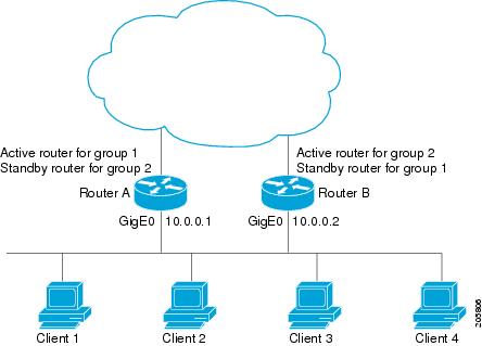
The following example shows Router A configured as the active router for group 1 with a priority of 110 and Router B configured as the active router for group 2 with a priority of 110. The default priority level is 100. Group 1 uses a virtual IP address of 10.0.0.3 and Group 2 uses a virtual IP address of 10.0.0.4.
Router A Configuration
Router(config)# hostname RouterA
!
Router(config)# interface GigabitEthernet 0/0/0
Router(config-if)# ip address 10.0.0.1 255.255.255.0
Router(config-if)# standby 1 priority 110
Router(config-if)# standby 1 preempt
Router(config-if)# standby 1 ip 10.0.0.3
Router(config-if)# standby 2 preempt
Router(config-if)# standby 2 ip 10.0.0.4
Router B Configuration
Router(config)# hostname RouterB
!
Router(config)# interface GigabitEthernet 0/0/0
Router(config-if)# ip address 10.0.0.2 255.255.255.0
Router(config-if)# standby 1 preempt
Router(config-if)# standby 1 ip 10.0.0.3
Router(config-if)# standby 2 priority 110
Router(config-if)# standby 2 preempt
Router(config-if)# standby 2 ip 10.0.0.4
Example: Improving CPU and Network Performance with HSRP Multiple Group Optimization
The following example shows how to configure an HSRP client and master group:
Device(config)# interface GigabitEthernet 0/0/0
Device(config-if)# no shutdown
Device(config-if)# standby mac-refresh 30
! Client Hello message interval
!
Device(config)# interface GigabitEthernet 0/0/1
Device(config-if)# no shutdown
Device(config-if)# ip vrf forwarding VRF2
Device(config-if)# ip address 10.0.0.100 255.255.0.0
Device(config-if)# standby 1 ip 10.0.0.254
Device(config-if)# standby 1 priority 110
Device(config-if)# standby 1 preempt
Device(config-if)# standby 1 name HSRP1
!Server group
!
Device(config)# interface GigabitEthernet 0/0/2
Device(config-if)# no shutdown
Device(config-if)# ip vrf forwarding VRF3
Device(config-if)# ip address 10.0.0.100 255.255.0.0
Device(config-if)# standby 2 ip 10.0.0.254
Device(config-if)# standby 2 follow HSRP1
! Client group
!
Device(config)# interface GigabitEthernet 0/0/3
Device(config-if)# no shutdown
Device(config-if)# ip vrf forwarding VRF4
Device(config-if)# ip address 10.0.0.100 255.255.0.0
Device(config-if)# standby 2 ip 10.0.0.254
Device(config-if)# standby 2 follow HSRP1
! Client group
Example: Configuring HSRP Support for ICMP Redirect Messages
Device A Configuration—Active for Group 1 and Standby for Group 2
Device(config)# interface GigabitEthernet 0/0/0
Device(config-if)# ip address 10.0.0.10 255.0.0.0
Device(config-if)# standby redirect
Device(config-if)# standby 1 priority 120
Device(config-if)# standby 1 preempt delay minimum 20
Device(config-if)# standby 1 ip 10.0.0.1
Device(config-if)# standby 2 priority 105
Device(config-if)# standby 2 preempt delay minimum 20
Device(config-if)# standby 2 ip 10.0.0.2
Device B Configuration—Standby for Group 1 and Active for Group 2
Device(config)# interface GigabitEthernet 0/0/0
Device(config-if)# ip address 10.0.0.11 255.0.0.0
Device(config-if)# standby redirect
Device(config-if)# standby 1 priority 105
Device(config-if)# standby 1 preempt delay minimum 20
Device(config-if)# standby 1 ip 10.0.0.1
Device(config-if)# standby 2 priority 120
Device(config-if)# standby 2 preempt delay minimum 20
Device(config-if)# standby 2 ip 10.0.0.2
Example: Configuring HSRP Virtual MAC Addresses and BIA MAC Address
In an Advanced Peer-to-Peer Networking (APPN) network, an end node is typically configured with the MAC address of the adjacent network node. In the following example, if the end nodes are configured to use 4000.1000.1060, HSRP group 1 is configured to use the same MAC address:
Device(config)# interface GigabitEthernet 0/0/0
Device(config-if)# ip address 10.0.0.1
Device(config-if)# standby 1 mac-address 4000.1000.1060
Device(config-if)# standby 1 ip 10.0.0.11
In the following example, the burned-in address of Token Ring interface 3/0 will be the virtual MAC address mapped to the virtual IP address:
Device(config)# interface token 3/0
Device(config-if)# standby use-bia
Note | You cannot use the standby use-bia command and the standby mac-address command in the same configuration. |
Example: Linking IP Redundancy Clients to HSRP Groups
The following example shows HSRP support for a static Network Address Translation (NAT) configuration. The NAT client application is linked to HSRP via the correlation between the name specified by the standby name command. Two devices are acting as HSRP active and standby, and the NAT inside interfaces are HSRP enabled and configured to belong to the group named “group1.”
Active Device Configuration
Device(config)# interface BVI 10
Device(config-if)# ip address 192.168.5.54 255.255.255.255.0
Device(config-if)# no ip redirects
Device(config-if)# ip nat inside
Device(config-if)# standby 10 ip 192.168.5.30
Device(config-if)# standby 10 priority 110
Device(config-if)# standby 10 preempt
Device(config-if)# standby 10 name group1
Device(config-if)# standby 10 track Ethernet 2/1
!
!
Device(config)# ip default-gateway 10.0.18.126
Device(config)# ip nat inside source static 192.168.5.33 10.10.10.5 redundancy group1
Device(config)# ip classless
Device(config)# ip route 10.10.10.0 255.255.255.0 Ethernet 2/1
Device(config)# ip route 172.22.33.0 255.255.255.0 Ethernet 2/1
Device(config)# no ip http server
Standby Device Configuration
Device(config)# interface BVI 10
Device(config-if)# ip address 192.168.5.56 255.255.255.255.0
Device(config-if)# no ip redirects
Device(config-if)# ip nat inside
Device(config-if)# standby 10 priority 95
Device(config-if)# standby 10 preempt
Device(config-if)# standby 10 name group1
Device(config-if)# standby 10 ip 192.168.5.30
Device(config-if)# standby 10 track Ethernet 3/1
Device(config-if)# exit
Device(config)# ip default-gateway 10.0.18.126
Device(config)# ip nat inside source static 192.168.5.33 3.3.3.5 redundancy group1
Device(config)# ip classless
Device(config)# ip route 10.0.32.231 255.255.255 Ethernet 3/1
Device(config)# ip route 10.10.10.0 255.255.255.0 Ethernet 3/1
Device(config)# no ip http server
Example: Configuring HSRP Version 2
The following example shows how to configure HSRP version 2 on an interface with a group number of 350:
Device(config)# interface vlan 350
Device(config-if)# standby version 2
Device(config-if)# standby 350 priority 110
Device(config-if)# standby 350 preempt
Device(config-if)# standby 350 timers 5 15
Device(config-if)# standby 350 ip 172.20.100.10
Example: Enabling SSO-Aware HSRP
The following example shows how to set the redundancy mode to SSO. HSRP is automatically SSO-aware when this mode is enabled.
Device(config)# redundancy
Device(config-red)# mode sso
If SSO HSRP is disabled using the no standby sso command, you can reenable it as shown in the following example:
Device(config)# interface GigabitEthernet 1/0/0
Device(config-if)# ip address 10.1.1.1 255.255.0.0
Device(config-if)# standby priority 200
Device(config-if)# standby preempt
Device(config-if)# standby sso
Example: Enabling HSRP MIB Traps
The following examples show how to configure HSRP on two devices and enable the HSRP MIB trap support functionality. As in many environments, one device is preferred as the active one. To configure a device’s preference as the active device, configure the device at a higher priority level and enable preemption. In the following example, the active device is referred to as the primary device. The second device is referred to as the backup device:
Device A
Device(config)# interface GigabitEthernet 0/0/0
Device(config-if)# ip address 10.1.1.1 255.255.0.0
Device(config-if)# standby priority 200
Device(config-if)# standby preempt
Device(config-if)# standby ip 10.1.1.3
Device(config-if)# exit
Device(config)# snmp-server enable traps hsrp
Device(config)# snmp-server host yourhost.cisco.com public hsrp
Device B
Device(config)#interface GigabitEthernet 1/0/0
Device(config-if)# ip address 10.1.1.2 255.255.0.0
Device(config-if)#  standby priority 101
Device(config-if)# standby ip 10.1.1.3
Device(config-if)# exit
Device(config)# snmp-server enable traps hsrp
Device(config)# snmp-server host myhost.cisco.com public hsrp
Example: HSRP BFD Peering
Hot Standby Router Protocol (HSRP) supports Bidirectional Forwarding Detection (BFD) as a part of the HSRP group member health monitoring system. Without BFD, HSRP runs as a process in a multiprocess system and cannot be guaranteed to be scheduled in time to service large numbers of groups with millisecond hello and hold timers. BFD runs as a pseudo-preemptive process and can therefore, be guaranteed to run when required. Only one BFD session between two devices can provide early failover notification for multiple HSRP groups.
In the following example, the standby bfd and the standby bfd all-interfaces commands are not displayed. HSRP support for BFD is enabled by default when BFD is configured on a device or an interface by using the bfd interval command. The standby bfd and standby bfd all-interfaces commands are needed only if BFD has been manually disabled on a device or an interface.
Device A
DeviceA(config)# ip cef
DeviceA(config)# interface FastEthernet2/0
DeviceA(config-if)#  no shutdown
DeviceA(config-if)# ip address 10.0.0.2 255.0.0.0
DeviceA(config-if)# ip router-cache cef
DeviceA(config-if)# bfd interval 200 min_rx 200 multiplier 3
DeviceA(config-if)# standby 1 ip 10.0.0.11
DeviceA(config-if)# standby 1 preempt
DeviceA(config-if)# standby 1 priority 110
DeviceA(config-if)# standby 2 ip 10.0.0.12
DeviceA(config-if)# standby 2 preempt
DeviceA(config-if)# standby 2 priority 110
Device B
DeviceB(config)# interface FastEthernet2/0
DeviceB(config-if)# ip address 10.1.0.22 255.255.0.0
DeviceB(config-if)# no shutdown
DeviceB(config-if)# bfd interval 200 min_rx 200 multiplier 3
DeviceB(config-if)# standby 1 ip 10.0.0.11
DeviceB(config-if)# standby 1 preempt
DeviceB(config-if)# standby 1 priority 90
DeviceB(config-if)# standby 2 ip 10.0.0.12
DeviceB(config-if)# standby 2 preempt
DeviceB(config-if)# standby 2 priority 80
Additional References
Related Documents
|
Related Topic |
Document Title |
|---|---|
|
Cisco IOS commands |
|
|
HSRP commands: complete command syntax, command mode, command history, defaults, usage guidelines, and examples |
Cisco IOS First Hop redundancy Protocols Command Reference |
|
HSRP for IPv6 |
“HSRP for IPv6” module |
|
Troubleshooting HSRP |
Standards
|
Standards |
Title |
|---|---|
|
No new or modified standards are supported by this feature, and support for existing standards has not been modified by this feature. |
-- |
MIBs
|
MIBs |
MIBs Link |
|---|---|
|
CISCO-HSRP-MIB CISCO-HSRP-EXT-MIB |
To locate and download MIBs for selected platforms, Cisco software releases, and feature sets, use Cisco MIB Locator found at the following URL: |
RFCs
|
RFCs |
Title |
|---|---|
|
RFC 792 |
Internet Control Message Protocol |
|
RFC 1828 |
IP Authentication Using Keyed MD5 |
|
RFC 2281 |
Cisco Hot Standby Router Protocol |
Technical Assistance
|
Description |
Link |
|---|---|
|
The Cisco Support and Documentation website provides online resources to download documentation, software, and tools. Use these resources to install and configure the software and to troubleshoot and resolve technical issues with Cisco products and technologies. Access to most tools on the Cisco Support and Documentation website requires a Cisco.com user ID and password. |
Feature Information for HSRP
The following table provides release information about the feature or features described in this module. This table lists only the software release that introduced support for a given feature in a given software release train. Unless noted otherwise, subsequent releases of that software release train also support that feature.
Use Cisco Feature Navigator to find information about platform support and Cisco software image support. To access Cisco Feature Navigator, go to www.cisco.com/go/cfn. An account on Cisco.com is not required.|
Feature Name |
Releases |
Feature Information |
|---|---|---|
|
FHRP—HSRP BFD Peering |
15.2(1)S |
The FHRP—HSRP BFD Peering feature introduces BFD in the HSRP group member health monitoring system. Previously, group member monitoring relied exclusively on HSRP multicast messages, which are relatively large and consume CPU memory to produce and check. In architectures where a single interface hosts a large number of groups, there is a need for a protocol with low CPU memory consumption and processing overhead. BFD addresses this issue and offers sub second health monitoring (failure detection in milliseconds) at a relatively low CPU impact. The following commands were introduced or modified by this feature: debug standby events neighbor,show standby,show standby neighbors,standby bfd, standby bfd all-interfaces. |
|
FHRP—HSRP Group Shutdown |
15.2(1)S |
The FHRP—HSRP Group Shutdown feature enables you to configure an HSRP group to become disabled (its state changed to Init) instead of having its priority decremented when a tracked object goes down. The following commands were modified by this feature:standby track, show standby. |
|
FHRP—HSRP Multiple Group Optimization |
15.2(1)S |
FHRP—HSRP Multiple Group Optimization feature improves the negotiation and maintenance of multiple HSRP groups configured on a subinterface. Only one HSRP group is required on a physical interface for the purposes of electing active and standby routers. This group is known as the master group. Other HSRP groups may be created on each subinterface and linked to the master group via the group name. These linked HSRP groups are known as client or slave groups. The following commands were introduced or modified by this feature: standby follow, show standby. |
|
FHRP—HSRP Support for IPv6 |
15.2(1)S |
Support for IPv6 was added. For more information see the "Configuring First Hop Redundancy Protocols in IPv6" module of the Cisco IOS IPv6 Configuration Guide. |
|
HSRP—ISSU |
15.2(1)S |
The HSRP--ISSU feature enables support for ISSU in HSRP. The In Service Software Upgrade (ISSU) process allows Cisco IOS software to be updated or otherwise modified while packet forwarding continues. In most networks, planned software upgrades are a significant cause of downtime. ISSU allows Cisco IOS software to be modified while packet forwarding continues, which increases network availability and reduces downtime caused by planned software upgrades. This document provides information about ISSU concepts and describes the steps taken to perform ISSU in a system. For more information about this feature, see the "Cisco IOS In Service Software Upgrade Process" module in the Cisco IOS High Availability Configuration Guide. There are no new or modified commands for this feature. |
|
HSRP MD5 Authentication |
15.2(1)S |
Prior to the introduction of the HSRP MD5 Authentication feature, HSRP authenticated protocol packets with a simple plain text string. The HSRP MD5 Authentication feature is an enhancement to generate an MD5 digest for the HSRP portion of the multicast HSRP protocol packet. This feature provides added security and protects against the threat from HSRP-spoofing software. The following commands were introduced or modified by this feature: show standby, standby authentication. |
|
HSRP Support for ICMP Redirects |
15.2(1)S |
The HSRP support for ICMP Redirects feature enables ICMP redirection on interfaces configured with HSRP. The following commands were introduced or modified by this feature: debug standby event , debug standby events icmp,show standby,standby redirects |
|
HSRP Support for MPLS VPNs |
15.2(1)S |
HSRP support for a Multiprotocol Label Switching (MPLS) Virtual Private Network (VPN) interface is useful when an Ethernet LAN is connected between two provider edge (PE) routers with either of the following conditions: There are no new or modified commands for this feature. |
|
HSRP Version 2 |
15.2(1)S |
HSRP Version 2 feature was introduced to prepare for further enhancements and to expand the capabilities beyond what is possible with HSRP version 1. HSRP version 2 has a different packet format than HSRP version 1. The following commands were introduced or modified by this feature: show standby, standby ip, standby version. |
|
SSO—HSRP |
15.2(1)S |
The SSO—HSRP feature alters the behavior of HSRP when a router with redundant RPs is configured for SSO. When an RP is active and the other RP is standby, SSO enables the standby RP to take over if the active RP fails. The following commands were introduced or modified by this feature: debug standby events, standby sso. |
Glossary
ARP—Address Resolution Protocol (ARP). ARP performs a required function in IP routing. ARP finds the hardware address, also known as Media Access Control (MAC) address, of a host from its known IP address. ARP maintains a cache (table) in which MAC addresses are mapped to IP addresses. ARP is part of all Cisco IOS systems running IP.
active device—The primary device in an HSRP group that is currently forwarding packets for the virtual device.
active RP—The active RP that controls the system, provides network services, runs the routing protocols, and presents the system management interface.
client group—An HSRP group that is created on a subinterface and linked to the master group via the group name.
HSRP—Hot Standby Router Protocol. Protocol that provides high network availability and transparent network-topology changes. HSRP creates a router group with a lead device that services all packets sent to the HSRP address. The lead device is monitored by other devices in the group, and if it fails, one of these standby HSRP devices inherits the lead position and the HSRP group address.
ISSU—In Service Software Upgrade. A process that allows Cisco IOS software to be updated or otherwise modified while packet forwarding continues. In most networks, planned software upgrades are a significant cause of downtime. ISSU allows Cisco IOS software to be modified while packet forwarding continues, which increases network availability and reduces downtime caused by planned software upgrades.
master group—An HSRP group that is required on a physical interface for the purposes of electing active and standby devices.
RF—Redundancy Facility. A structured, functional interface used to notify its clients of active and standby state progressions and events.
RP—Route Processor. A generic term for the centralized control unit in a chassis.
RPR—Route Processor Redundancy. RPR provides an alternative to the High System Availability (HSA) feature. HSA enables a system to reset and use a standby Route Processor (RP) if the active RP fails. Using RPR, you can reduce unplanned downtime because RPR enables a quicker switchover between an active and standby RP if the active RP experiences a fatal error.
RPR+—An enhancement to RPR in which the standby RP is fully initialized.
standby group—The set of devices participating in HSRP that jointly emulate a virtual device.
standby device—The backup device in an HSRP group.
standby RP—The backup RP.
switchover—An event in which system control and routing protocol execution are transferred from the active RP to the standby RP. Switchover may be a manual operation or may be induced by a hardware or software fault. Switchover may include transfer of the packet forwarding function in systems that combine system control and packet forwarding in an indivisible unit.
virtual IP address—The default gateway IP address configured for an HSRP group.
virtual MAC address—For Ethernet and FDDI, the automatically generated MAC address when HSRP is configured. The standard virtual MAC address used is: 0000.0C07.ACxy, where xy is the group number in hexadecimal. The functional address is used for Token Ring. The virtual MAC address is different for HSRP version 2.
 Feedback