- mGRE Tunnel Support over IPv6
- IP over IPv6 Tunnels
- Manually Configured IPv6 over IPv4 Tunnels
- Configuring Physical Interfaces
- Configuring Virtual Interfaces
- Implementing Tunnels
- Tunnel Route Selection
- MPLS VPN over mGRE
- IP Tunnel MIBs
- IF-MIBs
- Synchronous Ethernet (SyncE) ESMC and SSM
- 1+1 SR-APS Without Bridging
- IPv6 Rapid Deployment
- IPv6 Automatic 6to4 Tunnels
- IPv6 over IPv4 GRE Tunnels
- GRE IPv6 Tunnels
- ISATAP Tunnel Support for IPv6
- VRF-Aware Tunnels
- Ethernet over GRE Tunnels
- QoS on Ethernet over GRE Tunnels
- VRF-Aware IPv6 Rapid Deployment Tunnel
- IP Tunnel - GRE Key Entropy Support
Interface and Hardware Component Configuration Guide, Cisco IOS XE Release 3S
Bias-Free Language
The documentation set for this product strives to use bias-free language. For the purposes of this documentation set, bias-free is defined as language that does not imply discrimination based on age, disability, gender, racial identity, ethnic identity, sexual orientation, socioeconomic status, and intersectionality. Exceptions may be present in the documentation due to language that is hardcoded in the user interfaces of the product software, language used based on RFP documentation, or language that is used by a referenced third-party product. Learn more about how Cisco is using Inclusive Language.
- Updated:
- August 4, 2014
Chapter: VRF-Aware Tunnels
VRF-Aware Tunnels
Virtual Routing and Forwarding (VRF)-aware tunnels are used to connect customer networks separated by untrusted core networks or core networks with different infrastructures (IPv4 or IPv6).
- Finding Feature Information
- Prerequisites for VRF-Aware Tunnels
- Information About VRF-Aware Tunnels
- How to Configure VRF-Aware IPv6 Tunnels
- Configuration Examples for VRF-Aware Tunnels
- Additional References
- Feature Information for VRF-Aware Tunnels
Finding Feature Information
Your software release may not support all the features documented in this module. For the latest caveats and feature information, see Bug Search Tool and the release notes for your platform and software release. To find information about the features documented in this module, and to see a list of the releases in which each feature is supported, see the feature information table.
Use Cisco Feature Navigator to find information about platform support and Cisco software image support. To access Cisco Feature Navigator, go to www.cisco.com/go/cfn. An account on Cisco.com is not required.
Prerequisites for VRF-Aware Tunnels
-
You must configure customer edge networks. See the Configuring Customer Edge Networks For Tunneling section.
You must configure the customer and transport VRFs. See the Defining a VRF instance section.
Information About VRF-Aware Tunnels
Tunnel IP Source and Destination VRF Membership
You can configure the source and destination of a tunnel to belong to any VPN routing and forwarding (VRFs) tables. A VRF table stores routing data for each VPN. The VRF table defines the VPN membership of a customer site that is attached to the network access server (NAS). Each VRF table comprises an IP routing table, a derived Cisco Express Forwarding table, and guidelines and routing protocol parameters that control the information that is included in the routing table.
You can configure the tunnel source and destination to belong to any VRF or to a global table. The tunnel becomes disabled if no route to the tunnel destination is defined.
VRF-Aware Tunnels
Virtual Routing and Forwarding (VRF)-aware tunnels are used to connect customer networks that are separated by untrusted IPv4 or IPv6 core networks.
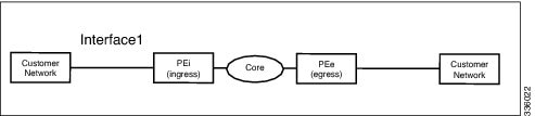
In the above topology, a tunnel is configured in the core network. Provider edge (PE) device PEi, is the tunnel head for packets entering on Interface 1. PE device PEe, is the tunnel tail for packets entering on Interface 1.
The VRF configured on Interface 1 is the customer VRF. Packets entering through Interface 1 are routed using this VRF. Packets exiting the tunnel are forwarded to this VRF. The routing by the customer VRF is called inner IP packet routing.
The VRF configured on the tunnel using the tunnel vrf command is the transport VRF. The transport VRF is the VRF that applies to the encapsulated payload and is used to look up the tunnel endpoints. This VRF is the same as the VRF associated with the physical interface over which the tunnel sends packets. The routing by the transport VRF is the outer IP packet routing.
The tunnel endpoint can be configured as an address from the global routing table or an address from a configured transport VRF table.
VRF-Aware IPv6 over IPv6 Tunnels
You can forward IPv6 packets on an untrusted IPv6 infrastructure by creating Virtual Routing and Forwarding (VRF)-aware IPv6 tunnels in it. These tunnels can have endpoints in a VRF table or in a global routing table. The tunnel modes used are tunnel mode gre ipv6 and tunnel mode ipv6.
VRF-Aware IPv4 over IPv6 Tunnels
You can forward IPv4 packets on an untrusted IPv6 infrastructure by creating Virtual Routing and Forwarding (VRF)-aware IPv4 tunnels in it. These tunnels can have endpoints in a VRF table or in a global routing table. The tunnel modes used are tunnel mode gre ipv6 and tunnel mode ipv6.
VRF-Aware IPv6 over IPv4 Tunnels
You can forward IPv6 packets on an untrusted IPv4 infrastructure by creating Virtual Routing and Forwarding (VRF)-aware IPv6 tunnels in it. These tunnels can have endpoints in a VRF table or in a global routing table. The tunnel modes used are tunnel mode gre ipv4 (default mode) and tunnel mode ipv4.
How to Configure VRF-Aware IPv6 Tunnels
To configure a VRF-aware tunnel, you need to perform the following steps:
Define the customer and transport VRF—Define a customer VRF if the tunnel is VRF-aware. Define a transport VRF if the tunnel endpoint needs to be in a VRF. See the Defining a VRF Instance section.
Set up the network—Configure relevant interfaces and configure relevant routes. Ensure that a valid route exists between the PE devices and the PE device and the customer network.
Configure the tunnel between the PE devices—See the Configuring a VRF-aware Tunnel section. - Configure the tunnel address
- Configure the tunnel source—This is an interface on the PE device.
- Configure the tunnel destination—This is tunnel source of the other PE device. For proper configuration of the tunnel, ensure that the tunnel destination is reachable from the PE device with a ping command (A valid route must exist to the tunnel destination).
- Configure the tunnel mode
Configure customer edge network. See the Configuring Customer Edge Networks For Tunneling section.
Configure static routes using the tunnel—Configure routes on the PE devices to remote CE networks using the configured tunnel.
Configuring a VRF-Aware Tunnel
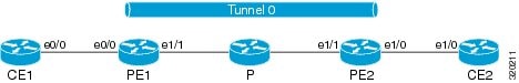
This task configures a tunnel between PE1 and PE2, as shown in the image below. The configuration task need to be repeated on both PE devices, PE1 and PE2.
1.
interface
type number
2.
vrf
forwarding
transport-vrf-name
4.
exit
5. Configure static routes between provider edge devices.
6.
interface
tunnel
number
7.
vrf
forwarding
customer-vrf-name
9.
tunnel source
interface-type interface-number
10.
tunnel destination
[ip-address |
ipv6-address]
11.
tunnel vrf
transport-vrf-name
12.
tunnel mode
{aurp | cayman | dvmrp | eon | gre | gre multipoint | gre ipv6 | ipip [decapsulate-any] | ipsec ipv4 | iptalk | ipv6 | ipsec ipv6 | mpls | nos | rbscp}
13.
exit
15.
end
DETAILED STEPS
Verify the IPv6 Tunnels. See Verifying IPv6 Tunnels.
Defining a VRF Instance
Perform this task to make a device Virtual Routing and Forwarding (VRF)-aware and to configure VRF-aware tunnels.
1.
vrf definition
vrf-name
2.
rd
route-distinguisher
3.
route-target export
route-target-ext-community
4.
route-target import
route-target-ext-community
5.
address-family {ipv4 | ipv6}
6.
exit-address-family
7.
exit
DETAILED STEPS
| Command or Action | Purpose | |
|---|---|---|
| Step 1 | vrf definition
vrf-name
Example: Device(config)# vrf definition green | Enters IP VRF configuration mode for defining a VRF routing table instance. |
| Step 2 | rd
route-distinguisher
Example: Device(config-vrf)# rd 1:1 | Specifies a route distinguisher (RD) for a VRF instance. |
| Step 3 | route-target export
route-target-ext-community
Example: Device(config-vrf)# route-target export 1:1 | Exports routing information to the target VPN extended community. |
| Step 4 | route-target import
route-target-ext-community
Example: Device(config-vrf)# route-target import 1:1 | Imports routing information to the target VPN extended community. |
| Step 5 | address-family {ipv4 | ipv6}
Example: Device(config-vrf)# address-family ipv6 | Enters VRF address-family configuration mode to configure a routing session using standard IPv4 or IPv6 address prefixes. |
| Step 6 | exit-address-family
Example: Device(config-vrf-af)# exit-address-family | Exits VRF address-family configuration mode and enters IP VRF configuration mode. |
| Step 7 | exit
Example: Device(config-vrf)# exit | Exits IP VRF configuration mode and enters global configuration mode. |
Configuring Customer Edge Networks for Tunneling
Perform this task to configure a customer edge (CE) network. In this configuration, the CE network is a network with CE devices connected to a provider edge (PE) device. PE1 and CE1 are connected and PE2 and CE2 are connected. Addresses must be configured accordingly.
To define a customer VRF, see the Defining a VRF instance section.
1.
interface
type number
2.
vrf
forwarding
customer-vrf-name
4.
exit
DETAILED STEPS
| Command or Action | Purpose | |||
|---|---|---|---|---|
| Step 1 | interface
type number
Example: Device(config)# interface Ethernet 0/0 | Configures an interface type and enters interface configuration mode. | ||
| Step 2 | vrf
forwarding
customer-vrf-name
Example: Device(config-if)# vrf forwarding green |
| ||
| Step 3 |
Example: Device(config-if)# ip address 10.22.22.22 255.255.255.0or Device(config-if)# ipv6 address 2001:DB8:1::1/64 | | ||
| Step 4 | exit
Example: Device(config-if)# exit | Exits interface configuration mode and enters global configuration mode. |
Verifying VRF-Aware Tunnels
Use the following commands to verify Virtual Routing and Forwarding (VRF)-aware tunnels:
1.
show tunnel interface
2.
show ip route
ip-address
3.
show ip route vrf
vrf-name ip-address
4.
ping ipv6
ipv6-address
source
ipv6-address
5.
ping vrf
vrf-name
ipv6-address
source
ipv6-address
6.
debug ipv6 icmp
DETAILED STEPS
| Step 1 |
show tunnel interface
This command displays detailed information about all tunnel interfaces. Example: The following is sample output from a provider edge (PE) device with Generic Routing Encapsulation (GRE) tunnel mode: Device# show tunnel interface
Tunnel0
Mode:GRE/IP, Destination 10.44.44.44, Source Loopback2
IP transport: output interface Ethernet1/0 next hop 10.0.0.2,
Tunnel header destination 10.44.44.44
Application ID 1: unspecified
Linestate - current up, cached up
Internal linestate - current up, evaluated up
Example: The following is sample output from a PE device with IPv6/IP tunnel mode: Device# show tunnel interface
Tunnel0
Mode:IPv6/IP, Destination 44.44.44.44, Source Loopback2
IP transport: output interface Ethernet1/0 next hop 2.0.0.2,
Tunnel header destination 44.44.44.44
Application ID 1: unspecified
Linestate - current up, cached up
Internal linestate - current up, evaluated up
The output is displayed and the tunnel mode is observed. |
| Step 2 |
show ip route
ip-address
This command displays detailed routing information to a tunnel destination address. Example: The following is sample output from a PE device with the tunnel endpoint in the global routing table: Device# show ip route 10.44.44.44
Routing entry for 10.44.44.44/32
Known via "ospf 1", distance 110, metric 21, type intra area
Last update from 10.0.0.2 on Ethernet1/0, 01:10:25 ago
Routing Descriptor Blocks:
* 10.0.0.2, from 10.44.44.44, 01:10:25 ago, via Ethernet1/0
Route metric is 21, traffic share count is 1
The following is sample output from a PE device having tunnel endpoints in the VRF table: Device# show ip route 10.44.44.44
% Network not in table
The output is displayed and you can observe if the tunnel destination is in the global routing table or not. |
| Step 3 |
show ip route vrf
vrf-name ip-address
This command displays detailed routing information to a destination IP address. Example: The following is sample output from PE1: Device# show ip route vrf green 10.4.4.4
Routing entry for 10.4.4.4/32
Known via "static", distance 1, metric 0
Routing Descriptor Blocks:
* 10.0.0.2, via Ethernet1/0
Route metric is 0, traffic share count is 1
The tunnel destination address 10.4.4.4 is not in the global routing table. |
| Step 4 |
ping ipv6
ipv6-address
source
ipv6-address
This command displays the status of the connectivity between two devices. Example: The following is sample output from a customer edge (CE) device CE1 with a ping command issued to CE2: Device# ping ipv6 2001:DB8:2::1 source 2001:DB8:1::1
Type escape sequence to abort.
Sending 5, 100-byte ICMP Echos to 2001:DB8:2::1, timeout is 2 seconds:
Packet sent with a source address of 2001:DB8:1::1
!!!!!
Success rate is 100 percent (5/5), round-trip min/avg/max = 0/2/4 ms
|
| Step 5 |
ping vrf
vrf-name
ipv6-address
source
ipv6-address
The VRF-ping tests the VPN connection. Example: The following is sample output from CE1 with a ping vrf command issued to CE2: Device# ping vrf green ipv6 2001:DB8:2::1 source 2001:DB8:1::1
Type escape sequence to abort.
Sending 5, 100-byte ICMP Echos to 2001:DB8:2::1, timeout is 2 seconds:
Packet sent with a source address of 2001:DB8:1::2%green
!!!!!
If the displayed output indicates success, the VPN is configured correctly. |
| Step 6 |
debug ipv6 icmp
This command displays debugging messages for IPv6 Internet Control Message Protocol (ICMP) transactions. Example: The following is sample output: Device# debug ipv6 icmp
ICMP Packet debugging is on
*Apr 6 14:08:10.743: ICMPv6: Received echo request, Src=2001:DB8:1::2, Dst=2001:DB8:2::1
*Apr 6 14:08:10.743: ICMPv6: Sent echo reply, Src=2001:DB8:2::1, Dst=2001:DB8:1::2
...
If the displayed output indicates success, the VPN is configured correctly. |
Configuration Examples for VRF-Aware Tunnels
- Example: Configuring a VRF-Aware Tunnel (Tunnel Endpoint in Global Routing Table)
- Example: Configuring a VRF-Aware Tunnel (Tunnel Endpoint in VRF)
Example: Configuring a VRF-Aware Tunnel (Tunnel Endpoint in Global Routing Table)
Example: Configuring CE1
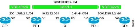
! ipv6 unicast-routing ipv6 cef ! vrf definition green rd 1:1 route-target export 1:1 route-target import 1:1 address-family ipv6 exit-address-family exit ! interface Ethernet0/0 vrf forwarding green no ip address ipv6 address 2001:DB8:2:1::1/64 no shutdown exit ! ! ipv6 route vrf green 2001:DB8:2:2::/64 2001:DB8:2:1::2 ipv6 route vrf green 2001:DB8:2:4::/64 2001:DB8:2:1::2 !
Example: Configuring PE1
ipv6 unicast-routing ipv6 cef ! vrf definition green rd 1:1 route-target export 1:1 route-target import 1:1 address-family ipv6 exit-address-family exit ! interface Tunnel0 no ip address vrf forwarding green ipv6 address 2001:DB8:2:4::1/64 tunnel source 10.22.22.22 tunnel destination 10.44.44.44 exit ! interface Ethernet0/0 vrf forwarding green no ip address ipv6 address 2001:DB8:2:1::2/64 no shutdown exit ! interface Ethernet1/1 no ip address ip address 10.22.22.22 255.255.255.0 no shutdown exit ! ip route 10.44.44.0 255.255.255.0 10.22.22.23 ipv6 route vrf green 2001:DB8:2:2::/64 Tunnel0 2001:DB8:2:4::2
Example: Configuring PE2
! ipv6 unicast-routing ipv6 cef ! vrf definition green rd 1:1 route-target export 1:1 route-target import 1:1 address-family ipv6 exit-address-family exit ! interface Tunnel0 vrf forwarding green no ipv6 address ipv6 address 2001:DB8:2:4::2/64 tunnel source 10.44.44.44 tunnel destination 10.22.22.22 exit ! interface Ethernet0/0 vrf forwarding green no ipv6 address ipv6 address 2001:DB8:2:2::1/64 no shutdown exit ! interface Ethernet1/0 no ip address ip address 10.44.44.44 255.255.255.0 no shutdown exit ! ip route 10.22.22.0 255.255.255.0 10.44.44.43 ! ipv6 route vrf green 2001:DB8:2:1::/64 Tunnel0 2001:DB8:2:4::1 !
Example: Configuring CE2
! ipv6 unicast-routing ipv6 cef ! vrf definition green rd 1:1 route-target export 1:1 route-target import 1:1 address-family ipv6 exit-address-family exit ! interface Ethernet0/0 vrf forwarding green no ipv6 address ipv6 address 2001:DB8:2:2::2/64 no shutdown exit ! ! ipv6 route vrf green 2001:DB8:2:1::/64 2001:DB8:2:2::1 ipv6 route vrf green 2001:DB8:2:4::/64 2001:DB8:2:2::1 !
Example: Configuring Device X
! interface Ethernet1/0 no ip address ip address 10.44.44.43 255.255.255.0 no shutdown exit ! interface Ethernet1/1 no ip address ip address 10.22.22.23 255.255.255.0 no shutdown exit !
Example: Verifying the Tunnel Configuration
From CE1
Device# ping vrf green ipv6 2001:db8:2:2::2 Type escape sequence to abort. Sending 5, 100-byte ICMP Echos to 2001:DB8:2:2::2, timeout is 2 seconds: !!!!! Success rate is 100 percent (5/5), round-trip min/avg/max = 1/2/6 ms Device# ping vrf green ipv6 2001:db8:2:2::2 source 2001:db8:2:1::1 Type escape sequence to abort. Sending 5, 100-byte ICMP Echos to 2001:DB8:2:2::2, timeout is 2 seconds: Packet sent with a source address of 2001:DB8:2:1::1 !!!!! Success rate is 100 percent (5/5), round-trip min/avg/max = 1/1/1 ms
From PE1
Device# show tunnel interface
Tunnel0
Mode:GRE/IP, Destination 10.44.44.44, Source 10.22.22.22
IP transport: output interface Ethernet1/1 next hop 10.22.22.23
Application ID 1: unspecified
Linestate - current up
Internal linestate - current up, evaluated up
Tunnel Source Flags: Local
Transport IPv4 Header DF bit cleared
OCE: IP tunnel decap
Provider: interface Tu0, prot 47
Performs protocol check [47]
Protocol Handler: GRE: opt 0x0
ptype: ipv4 [ipv4 dispatcher: punt]
ptype: ipv6 [ipv6 dispatcher: from if Tu0]
ptype: mpls [mpls dispatcher: drop]
ptype: otv [mpls dispatcher: drop]
ptype: generic [mpls dispatcher: drop]
There are 0 tunnels running over the EON IP protocol
There are 0 tunnels running over the IPinIP protocol
There are 0 tunnels running over the NOSIP protocol
There are 0 tunnels running over the IPv6inIP protocol
There are 0 tunnels running over the RBSCP/IP protocol
Device# show ip route 10.44.44.44
Routing entry for 10.44.44.0/24
Known via "static", distance 1, metric 0
Routing Descriptor Blocks:
* 10.22.22.23
Route metric is 0, traffic share count is 1
Device# debug ipv6 icmp
ICMP Packet debugging is on
*Jan 1 10:57:37.882: ICMPv6: Sent R-Advert, Src=FE80::A8BB:CCFF:FE00:5200, Dst=FF02::1
*Jan 1 11:00:18.634: ICMPv6: Received R-Advert, Src=FE80::A8BB:CCFF:FE00:5200,Dst=FF02::1
Example: Configuring a VRF-Aware Tunnel (Tunnel Endpoint in VRF)
Example: Configuring CE1
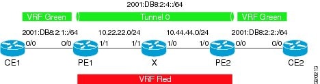
! ipv6 unicast-routing ipv6 cef ! vrf definition green rd 1:1 route-target export 1:1 route-target import 1:1 address-family ipv6 exit-address-family exit ! interface Ethernet0/0 vrf forwarding green no ip address ipv6 address 2001:DB8:2:1::1/64 no shutdown exit ! ! ipv6 route vrf green 2001:DB8:2:2::/64 2001:DB8:2:1::2 ipv6 route vrf green 2001:DB8:2:4::/64 2001:DB8:2:1::2 !
Example: Configuring PE1
ipv6 unicast-routing ipv6 cef ! vrf definition green rd 1:1 route-target export 1:1 route-target import 1:1 address-family ipv6 exit-address-family exit ! vrf definition red rd 2:2 route-target export 2:2 route-target import 2:2 address-family ipv4 exit-address-family exit ! interface Tunnel0 no ip address vrf forwarding green ipv6 address 2001:DB8:2:4::1/64 tunnel source 10.22.22.22 tunnel destination 10.44.44.44 tunnel vrf red exit ! interface Ethernet0/0 vrf forwarding green no ip address ipv6 address 2001:DB8:2:1::2/64 no shutdown exit ! interface Ethernet1/1 vrf forwarding red no ip address ip address 10.22.22.22 255.255.255.0 no shutdown exit ! ip route vrf red 10.44.44.0 255.255.255.0 10.22.22.23 ipv6 route vrf green 2001:DB8:2:2::/64 Tunnel0 2001:DB8:2:4::2
Example: Configuring PE2
! ipv6 unicast-routing ipv6 cef ! vrf definition green rd 1:1 route-target export 1:1 route-target import 1:1 address-family ipv6 exit-address-family exit ! vrf definition red rd 2:2 route-target export 2:2 route-target import 2:2 address-family ipv4 exit-address-family exit ! interface Tunnel0 vrf forwarding green no ipv6 address ipv6 address 2001:DB8:2:4::2/64 tunnel source 10.44.44.44 tunnel destination 10.22.22.22 tunnel vrf red exit ! interface Ethernet0/0 vrf forwarding green no ipv6 address ipv6 address 2001:DB8:2:2::1/64 no shutdown exit ! interface Ethernet1/0 vrf forwarding red no ip address ip address 10.44.44.44 255.255.255.0 no shutdown exit ! ip route vrf red 10.22.22.0 255.255.255.0 10.44.44.43 ! ipv6 route vrf green 2001:DB8:2:1::/64 Tunnel0 2001:DB8:2:4::1 !
Example: Configuring CE2
! ipv6 unicast-routing ipv6 cef ! vrf definition green rd 1:1 route-target export 1:1 route-target import 1:1 address-family ipv6 exit-address-family exit ! interface Ethernet0/0 vrf forwarding green no ipv6 address ipv6 address 2001:DB8:2:2::2/64 no shutdown exit ! ! ipv6 route vrf green 2001:DB8:2:1::/64 2001:DB8:2:2::1 ipv6 route vrf green 2001:DB8:2:4::/64 2001:DB8:2:2::1 !
Example: Configuring Device X
! interface Ethernet1/0 vrf forwarding red no ip address ip address 10.44.44.43 255.255.255.0 no shutdown exit ! interface Ethernet1/1 vrf forwarding red no ip address ip address 10.22.22.23 255.255.255.0 no shutdown exit !
Example: Verifying the Tunnel Configuration
From CE1
Device# ping vrf green ipv6 2001:db8:2:2::2 Type escape sequence to abort. Sending 5, 100-byte ICMP Echos to 2001:DB8:2:2::2, timeout is 2 seconds: !!!!! Success rate is 100 percent (5/5), round-trip min/avg/max = 1/2/6 ms Device# ping vrf green ipv6 2001:db8:2:2::2 source 2001:db8:2:1::1 Type escape sequence to abort. Sending 5, 100-byte ICMP Echos to 2001:DB8:2:2::2, timeout is 2 seconds: Packet sent with a source address of 2001:DB8:2:1::1 !!!!! Success rate is 100 percent (5/5), round-trip min/avg/max = 1/1/1 ms
From PE1
Device# show tunnel interface
Tunnel0
Mode:GRE/IP, Destination 10.44.44.44, Source 10.22.22.22
IP transport: output interface Ethernet1/1 next hop 10.22.22.23
Application ID 1: unspecified
Linestate - current up
Internal linestate - current up, evaluated up
Tunnel Source Flags: Local
Transport IPv4 Header DF bit cleared
OCE: IP tunnel decap
Provider: interface Tu0, prot 47
Performs protocol check [47]
Protocol Handler: GRE: opt 0x0
ptype: ipv4 [ipv4 dispatcher: punt]
ptype: ipv6 [ipv6 dispatcher: from if Tu0]
ptype: mpls [mpls dispatcher: drop]
ptype: otv [mpls dispatcher: drop]
ptype: generic [mpls dispatcher: drop]
There are 0 tunnels running over the EON IP protocol
There are 0 tunnels running over the IPinIP protocol
There are 0 tunnels running over the NOSIP protocol
There are 0 tunnels running over the IPv6inIP protocol
There are 0 tunnels running over the RBSCP/IP protocol
Device# show ip route 10.44.44.44

% Network not in table
Device# show ip route vrf red 10.44.44.44
Routing Table: red
Routing entry for 10.44.44.0/24
Known via "static", distance 1, metric 0
Routing Descriptor Blocks:
* 10.22.22.23
Route metric is 0, traffic share count is 1
Device# debug ipv6 icmp
ICMP Packet debugging is on
*Jan 1 10:57:37.882: ICMPv6: Sent R-Advert, Src=FE80::A8BB:CCFF:FE00:5200, Dst=FF02::1
*Jan 1 11:00:18.634: ICMPv6: Received R-Advert, Src=FE80::A8BB:CCFF:FE00:5200,Dst=FF02::1
Additional References
Related Documents
Related Topic |
Document Title |
|---|---|
|
IPv6 addressing and connectivity |
Cisco IOS IPv6 Configuration Guide |
|
Cisco IOS commands |
|
|
IPv6 commands |
|
|
Cisco IOS IPv6 features |
Standards and RFCs
Standard/RFC |
Title |
|---|---|
|
RFCs for IPv6 |
IPv6 RFCs |
Technical Assistance
Description |
Link |
|---|---|
|
The Cisco Support and Documentation website provides online resources to download documentation, software, and tools. Use these resources to install and configure the software and to troubleshoot and resolve technical issues with Cisco products and technologies. Access to most tools on the Cisco Support and Documentation website requires a Cisco.com user ID and password. |
Feature Information for VRF-Aware Tunnels
The following table provides release information about the feature or features described in this module. This table lists only the software release that introduced support for a given feature in a given software release train. Unless noted otherwise, subsequent releases of that software release train also support that feature.
Use Cisco Feature Navigator to find information about platform support and Cisco software image support. To access Cisco Feature Navigator, go to www.cisco.com/go/cfn. An account on Cisco.com is not required.|
Feature Name |
Releases |
Feature Information |
|---|---|---|
|
VRF-Aware Tunnels |
Cisco IOS XE Release 3.8S |
Virtual Routing and Forwarding (VRF)-aware tunnels are used to connect customer networks separated by untrusted core networks or core networks with different infrastructures (IPv4 or IPv6). The following command was modified to support IPv6 transport: tunnel vrf. |
 Feedback