Aironet 1570 Deployment Guide

Overview
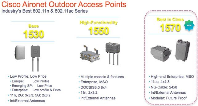
This deployment guide introduces the newest addition to the outdoor portfolio, the AP1572. The 1572 highlights include:
-
Most advanced carrier-grade outdoor Wi-Fi AP.
-
Dual-band 2.4 and 5 GHz with 802.11ac Wave 1 support on the integrated 5 GHz radio.
-
Maximum radiated RF power allowed by law.
-
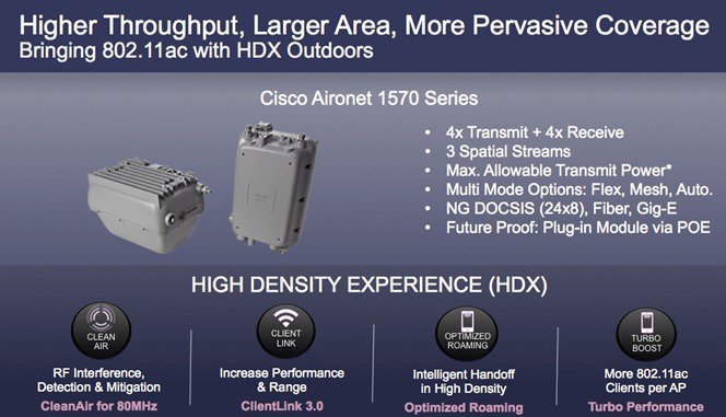
High Density Experience (HDX):
-
Cisco® CleanAir™ 2.0 technology provides integrated spectrum intelligence for a self configuring and self-healing network on 80 MHz channels.
-
ClientLink 3.0 improves reliability and coverage for legacy 802.11n and 802.11ac data rates.
-
Optimized Roaming to allow clients to join the most optimal access point.
-
Turbo performance which uses Cisco ASIC design to maximize radio performance.
-
-
Improved 802.11ac range and performance with 4x4:3 multiple-input multiple-output (MIMO) technology.
-
1.3 Gbps (5 GHz) 802.11ac data rates.
-
Cisco Flexible Antenna Port technology.
-
DOCSIS 3.0 / EuroDOCSIS / JapanDOCSIS 3.0, 24x8 hybrid fiber-coaxial (HFC) cable modem option.
-
Improved radio sensitivity and range performance with four antenna MIMO and three spatial streams.
-
Multiple uplink options (Gigabit Ethernet-10/100/1000 BaseT, Fiber SFP, Cable modem).
-
Power: AC, DC, Cable, UPOE, PoE-Out (802.3at).
-
4G LTE coexistence.
-
NEMA Type 4X certified enclosure.
-
Module option: Investment protection and future proofing.
-
Low visual profile design.
-
Unified or autonomous operation.

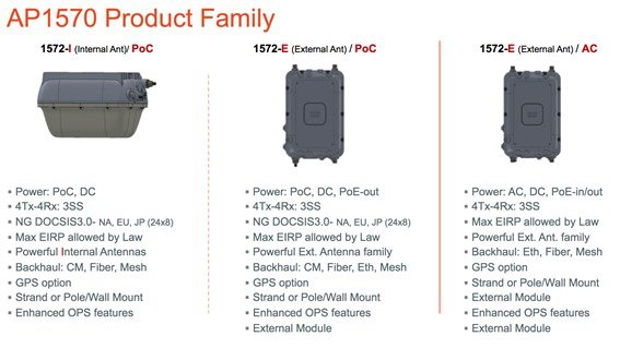
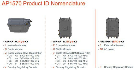
There are three 1572 models:
-
Cisco Aironet 1572IC—Internal Antennas with cable modem
-
Cisco Aironet 1572EC—External Antennas with cable modem
-
Cisco Aironet 1572EAC—External Antenna AC powered Model
AP1572 Availability and Compatibility
|
OS |
WLC |
MSE |
Prime Infrastructure |
ISE |
|---|---|---|---|---|
|
AirOS |
8.0.110.0 |
8.0 |
2.2 |
1.2 |
|
IOS XE |
3.7 |
8.0 |
2.2 |
1.2 |
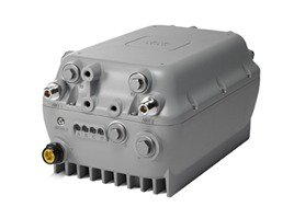
The New AP1572
The AP1572 series is an industry leading carrier grade 802.11ac access point (AP). The AP1572 has three models, such as an internal antenna model with cable mode, an external model with cable modem, and an external antenna model.
The AP1572 can operate in the following modes:
-
Unified Modes:
-
Local
-
Flexconnect
-
Bridge
-
Flexconnect with Bridge
-
Monitor
-
Spectrum Expert
-
Sniffer
-
Rogue Detector
-
Aironet 1572IC Product Details
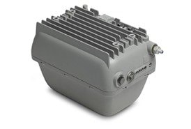
The 1572IC has the following features:
-
Two radios (2.4 GHz and 5 GHz):
-
2 GHz: 4x4:3
-
5 GHz: 4x4:3
-
-
Power Options:
-
40 – 90 VAC, 50 – 60 Hz, quasi-square wave, Power over Cable
-
10 – 16 VDC
-
-
Console Port
-
LTE and WIMAX Signal Rejection (2.1 / 2.3 GHz; 30 dB; 2.5 GHz; 35 dB)
-
DOCSIS and EuroDOCSIS 3.0 24x8
-
GPS Option

The 1572IC has two Gigabit Ethernet ports, the Ethernet port and SFP port. Either the Ethernet port, SFP port, or Cable modem can provide uplink access to the WLC, but only one uplink port can be used for WLC access at a given time. LAG for redundancy is not supported. Ethernet Bridged wired clients or Daisy-chained APs should be connected to the Ethernet port only. The SFP port requires an additional SFP connector to be inserted into the SFP port.
The 1572IC can be powered either by DC or Power over cable. The LED can be used to determine the status of the AP. The LED flashing sequences are listed in the LED Flashing Sequences section.
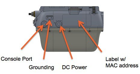
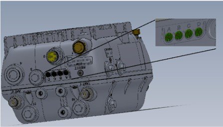
The Console port is located on the side of the AP, covered by a metal cap. The AP MAC address is located on the side of the AP and should be added to the WLC’s MAC Filter list or to a External AAA, for the AP to join a WLC while in Bridge mode.
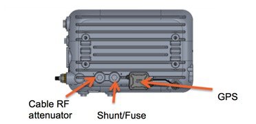
The additional cable attenuation can be added without opening the AP. The shunt and fuse can also be changed. This allows installers easy access.
Aironet 1572EC Product Details
The 1572EC has the following features:
-
Two radios (2.4 GHz and 5 GHz):
-
2 GHz: 4x4:3
-
5 GHz: 4x4:3
-
-
Power Options:
-
40 – 90 VAC, 50 – 60 Hz, quasi-square wave, Power over Cable
-
10 – 16 VDC
-
802.3at PoE Out Capable
-
-
Console Port
-
LTE and WIMAX Signal Rejection (2.1 / 2.3 GHz; 30 dB; 2.5 GHz; 35 dB)
-
GPS Option
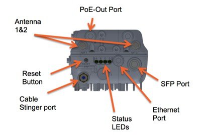
The 1572EC has three Gigabit Ethernet ports, the Ethernet port, SFP port, and the PoE-Out port. Either the Ethernet port, SFP port, PoE-Out port or Cable modem can provide uplink access to the WLC, but only one uplink port can be used for WLC access at a given time. LAG for redundancy is not supported. Ethernet Bridged wired clients or Daisy-chained APs should be connected to either the Ethernet port or PoE-Out port only. The SFP port requires an additional SFP connector to be inserted into the SFP port.
The LED can be used to determine the status of the AP. The LED flashing sequences are listed in the LED Flashing Sequences section.
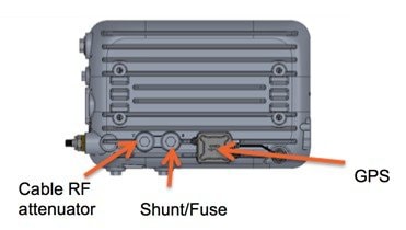
The additional cable attenuation can be added without opening the AP. The shunt and fuse can also be changed. This allows installers easy access.
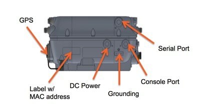
The Console port is located on the side of the AP, covered by a metal cap. The AP MAC address is located on the side of the AP and should be added to the WLC’s MAC Filter list or to a External AAA, for the AP to join a WLC while in Bridge mode.
Aironet 1572EAC Product Details
The 152EAC has the following features:
-
Two radios (2.4 GHz and 5 GHz):
-
2 GHz: 4x4:3
-
5 GHz: 4x4:3
-
-
Power Options:
-
100 – 277 VAC, 50 – 60 Hz
-
10 – 16 VDC
-
UPoE
-
PoE with AIR-PWRINJ1500-2=
-
802.3at PoE Out Capable when powered via AC/DC power
-
-
Console Port
-
LTE and WIMAX Signal Rejection (2.1 / 2.3 GHz; 30 dB; 2.5 GHz; 35 dB)
-
GPS Option
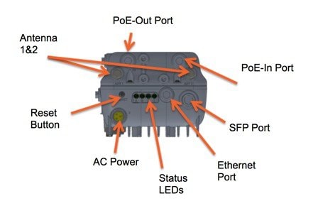
The 1572EAC has four Gigabit Ethernet ports, the Ethernet port, SFP port, PoE-In port, and the PoE-Out port. Any port can be used to provide uplink access back to a WLC, but only one uplink port can be used for WLC access at a given time. LAG for redundancy is not supported. Ethernet Bridged wired clients or Daisy-chained APs should be connected to either the Ethernet port or PoE-Out port only. The SFP port requires an additional SFP connector to be inserted into the SFP port.
The 1572EAC can be powered either by PoE-in, using a PoE injector or UPoE, AC, DC, or Power over cable. The PoE injector can power the AP, even if the AP has no WAN connectivity and is operating as a Mesh AP.
The LED can be used to determine the status of the AP. The LED flashing sequences are listed in the LED Flashing Sequences section.
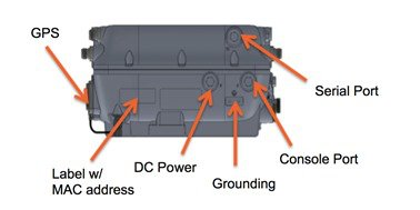
The Console port is located on the side of the AP, covered by a metal cap. The AP MAC address is located on the side of the AP and should be added to the WLC’s MAC Filter list or to a External AAA, for the AP to join a WLC while in Bridge mode.
Hardware Components
This section explains the hardware components in AP1572.
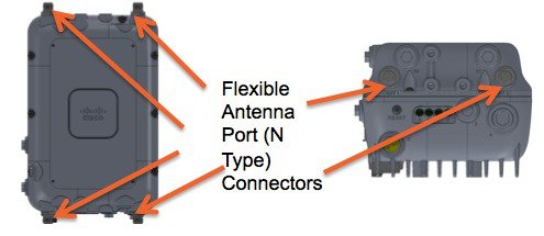
1572 Antenna Ports
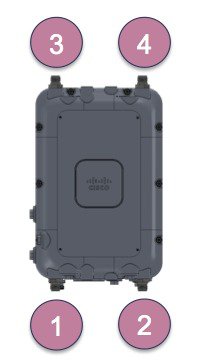
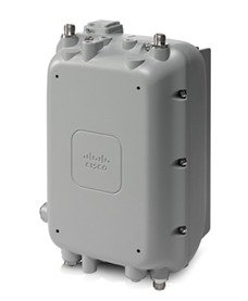
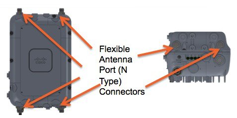
The AP1572EC has four antenna ports with N Type connectors, two on the top of the access point (AP) and two on the bottom of the AP. When in Dual band mode, all antenna ports are used creating four transmitters and four receivers with three spatial streams (4x4:3) for both 2.4 GHz and 5 GHz. Antennas that support multiple bands are called Dual Radiating Element (DRE), and they contain dual radiating element inside the antenna.
When in Single band mode, the bottom antenna ports (port 1 and port 2) are used for 2.4 GHz antennas (2x2:2), and the top ports are for 5 GHz (2x2:2) (port 3 and port 4). Antennas that support a single band are Single Radiating Elements (SRE), and they contain single radiating elements inside the antenna. The AP1572IC has internal antennas, which cannot be configured as part of the Antenna Flexport feature.
|
Antenna Port 1 |
Antenna Port 2 |
Antenna Port 3 |
Antenna Port 4 |
|
|---|---|---|---|---|
|
Single Band 2x2 |
2.4 GHz |
2.4 GHz |
5 GHz |
5 GHz |
|
Dual Band 2x2 |
2.4 and 5 GHz |
2.4 and 5 GHz |
— |
— |
|
Dual Band 3x3 |
2.4 and 5 GHz |
2.4 and 5 GHz |
2.4 and 5 GHz |
— |
|
Dual Band 4x4 |
2.4 and 5 GHz |
2.4 and 5 GHz |
2.4 and 5 GHz |
2.4 and 5 GHz |
Antenna Options for the AP1572E
The AP1572E has the similar antennas to both the 1532 and 1552. Below are the antenna options:
|
Product ID |
Frequency Band |
Gain |
Type |
Required Quantity (#Ports) |
|---|---|---|---|---|
|
AIR-ANT2568VG-N |
2.4 / 5 GHz |
6 / 8 dBi |
Omnidirectional |
4 (1) |
|
AIR-ANT2547VG-N |
2.4 / 5 GHz |
4 / 7 dBi |
Omnidirectional |
4 (1) |
|
AIR-ANT2588P3M-N= |
2.4 / 5 GHz |
8 / 8 dBi |
Directional 120x30° |
1 (3) |
|
AIR-ANT2513P4M-N= |
2.4 / 5 GHz |
13/13 dBi |
Directional 30x30° |
1 (4) |
|
AIR-ANT2450V-N= |
2.4 GHz |
5 dBi |
Omnidirectional |
2 (1) |
|
AIR-ANT2480V-N= |
2.4 GHz |
8 dBi |
Omnidirectional |
2 (1) |
|
AIR-ANT2413P2M-N= |
2.4 GHz |
13 dBi |
Directional 30x30° |
1 (2) |
|
AIR-ANT5180V-N= |
5 GHz |
8 dBi |
Omnidirectional |
2 (1) |
|
AIR-ANT5114P2M-N= |
5 GHz |
14 dBi |
Directional 30x30° |
1 (2) |
New Antenna AIR-ANT2568VG-N
|
Parameter |
Performance |
|---|---|
|
Frequency |
2.4 – 2.5 GHz / 5.250 – 5.925 GHz |
|
Gain |
6 dBi / 8 dBi |
|
Polarization |
Linear, Vertical |
|
E-Plane 3 dB Beamwidth |
22° / 11° |
|
H-Plane 3 dB |
Omnidirectional |
|
RF Connector |
Type N, fixed (male) |
|
Power |
1 Watt |
|
Weight |
0.20 Kg |
|
Radome |
Polycarbonate, UV, gray |
|
Operational Temperature |
-30°C to +70°C |
|
Mounting |
Connector fixed, upright and inverted orientation |
|
Dimensions (mm) |
38.1 diameter x 376.8 length |
The antenna patterns are as follows:
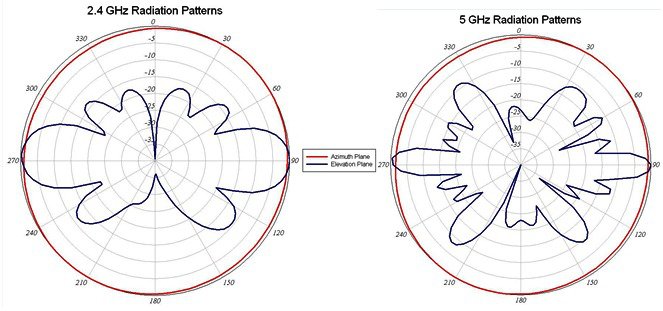
 Note |
When the AP1572E with AIR-ANT2568VG-N antennas is configured in the –B Regulatory Domain, UNII-1 channels can not be used. |
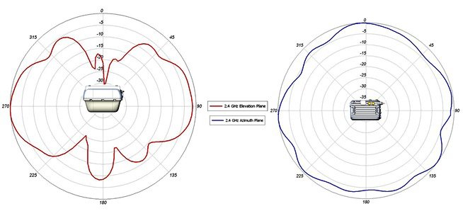
Antenna Options for the AP1572IC
The 1572IC has internal antennas.
|
Parameter |
Performance |
|---|---|
|
Frequency |
2.4 – 2.5 GHz / 5.250 – 5.875 GHz |
|
Gain |
4 dBi / 6 dBi |
|
Polarization |
Linear, Vertical |
|
E-Plane 3 dB Beamwidth |
55° / 25° |
|
H-Plane 3 dB |
Omnidirectional |
|
RF Connector |
Internal |
The antenna patterns are as follows:

Powering the AP1572
The AP1572 can be powered via multiple power sources depending on the AP module:
-
AIR-AP1572EC/AIR-AP1572IC
-
Power-over-cable (PoC)
-
External DC Power
-
-
AIR-AP1572EAC
-
AC Power
-
External DC
-
PoE-IN
-
|
Model |
TX/RX:SS |
Switch Power |
PWR-INJ1500-2 |
PoE-Out |
AC Power |
DC Power |
Power over Cable (PoC) |
|---|---|---|---|---|---|---|---|
|
1572I-C |
4x4:3 |
— |
— |
— |
— |
√ |
√ |
|
1572E-C |
4x4:3 |
— |
— |
√ |
— |
√ |
√ |
|
1572E-AC |
4x4:3 |
UPoE Only |
√ |
802.3at if powered by AC or DC |
√ |
√ |
— |
Note |
The 1572EAC can switch between AC and DC power without rebooting, but if the AP switches to PoE power, the AP will reboot. The 1572 only operates in full power mode, meaning the AP will not power with a lesser power supply. |
AP1572 Accessories
The following accessories are available with the AP1572:
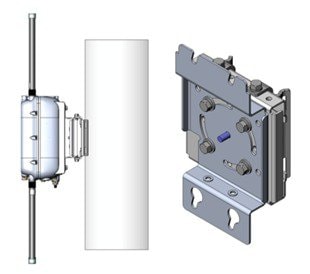
AIR-ACC1572-PMK1 (=)
Pole mount brackets, available as option or as an add-on:
-
Pole diameter: 2-6” (> 80% cases)
-
Low profile (1” from Pole)
-
Vertical mount only
-
No install tool need
-
Light weight (< 0.5 kg)
-
Simple installation
To install the wall / pole mount bracket, perform the following steps:
-
Pull, lock, and tighten bands on the AIR-ACC1572-PMK1 around the pole.
-
Insert four screws into the AP.
-
Slide AP into screw holes on the mounting bracket.
-
Tighten the screws on the AP, securing the AP into the mounting bracket.

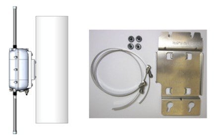
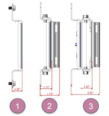
AIR-ACC1572-PMK2 (=)
Wall / Pole mount bracket, available as option or as an add-on:
-
Pole diameter: 2-16” (< 20% cases)
-
Pole or wall mount option
-
Band Install Tool needed for installation
Configuration Options:
-
Option 1: Wall Mount, 1 piece, others discarded
-
Option 2: Vertical only 5-8’, 3 pieces
-
Option 3: All scenarios, 2-16”, 4 pieces
AIR-ACC1572-PMK3 (=)
Mounting kit for the 1572IC:
-
Pole diameter: 2-16” (< 20% cases)
-
Pole or wall mount option
-
Band Install Tool needed for installation
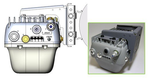
Note |
The AIR-ACC1572-PMK3(=) is recommended for use with the AP1572IC only. |
AIR-ACC1572-SMK1, 2, 3
There are three cable strand-mounting kits. For more details, see the 1570 Series Hardware Installation Guide.
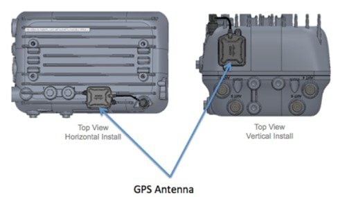
AIR-ANT-GPS-1=
This is an add-on GPS module that can be installed on all AP1572 models.
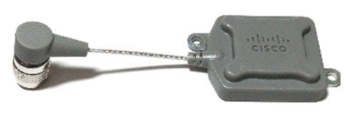
This module can be added on to an AP1572 at any time. It does not need to be ordered with the AP. The GPS antenna can be mounted to face the sky, regardless of the AP orientation. Below are examples of GPS antenna placement in a horizontal Install and vertical install.
The GPS coordinates are available in the WLC GUI under theWireless >AP_Name >General tabs:

This can also be view from the WLC CLI using the command:
(Cisco WLC) >show ap gps
                           			 location summary
AP Name             GPS Present   Latitude        Longitude       Altitude        GPS location Age
------------------  -----------   ------------    -------------   -------------   ------------------------

1570-RAP1           YES           37.42034194     -121.91973098   25.10  meters   000 days, 00 h 00 m 19 s
1570-MAP1           YES           37.41970399     -121.92051996   10.00  meters   000 days, 00 h 00 m 12 s
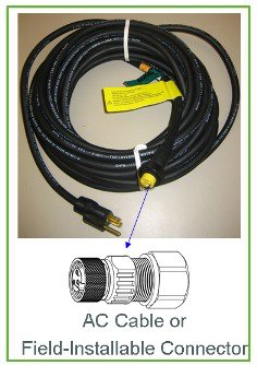
AIR-CORD-R3P-40NA=
Cisco AC power cord for the AP1572EAC
Flexible Antenna-port Configuration
There are two terms that are used when referring to Antenna Band Mode Configurations:
-
Dual Antenna Band Mode—All four antenna ports are used for dual band 2.4 GHz / 5 GHz Dual Radiating Elements (DRE) antennas (4x4:3SS).
-
Single Antenna Band Mode—The top two ports, port 3, and port 4 are used for 5 GHz Single Radiating Elements (SRE) antennas, while the bottom two ports, port 1, and port 2 are used for 2.4 GHz SRE antennas (2x2:2SS).
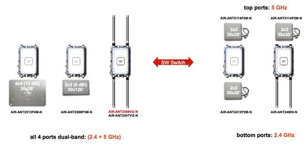
Note |
Antenna Band Mode is only available on the 1572EC and 1572EAC models, with external antennas. |
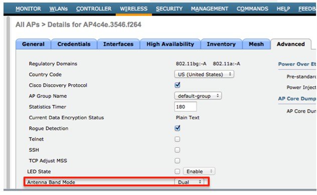
Configuring Antenna Band Mode from the WLC GUI
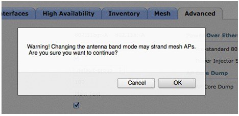
To change the Antenna Band Mode, from the WLC GUI, go to the Wireless > Access Point > AP_NAME > Advanced tabs, and then select Dual / Single.
Note |
Misconfiguring the Antenna Band Mode can strand a mesh AP. So, ensure that your physical antennas are properly configured before changing the Antenna Band Mode. |
Configuring Antenna Band Mode from the WLC CLI
The Antenna Band Mode can be changed via the WLC CLI by issuing the command:
(Cisco Controller) >config ap antenna-band-mode
                        		  <single|dual> <ap_name>
The Antenna Band mode can be displayed by issuing the command:
(Cisco Controller) >show ap config general
                        		  <AP_NAME>
The output will contain many fields, one of which is the Antenna Band Mode:
Antenna Band Mode ............................... Dual
Configuring Antenna Band Mode from the AP CLI
Antenna Band Mode can be changed in the AP CLI, by issuing the command:
AP#capwap ap ant-band-mode <dual/single>
Daisy Chaining with the 1572
One of the key features of the 1572 access point (AP) is the ability to “daisy chain” APs while they are operating as Mesh APs (MAPs). By “daisy chaining” MAPs, customers can either operate the APs as a serial backhaul, allowing different channels for uplink and downlink access thus improving backhaul bandwidth, or to extend universal access. Extending universal access allows a customer to connect a local mode or flexconnect mode 1572 AP to the Ethernet port of a MAP, thus extending the network to provide better client access. These features are explained in detail in the following sections.
In the 8.0MR release, when the 1572 is configured as a primary AP, the following APs are supported as subordinate APs:
-
1572EAC
-
1572EC
-
1572IC
-
1552
-
1532E/I
-
3700P
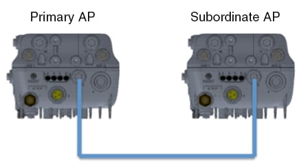
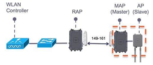
Daisy-chained access points need to be cabled differently depending on the AP type of their terminating subordinate AP.
If both the primary AP and subordinate APs are 1572s, there should be an Ethernet cable from the primary AP’s Ethernet port to the subordinate AP’s Ethernet port. Daisy chaining should be enabled on both APs.
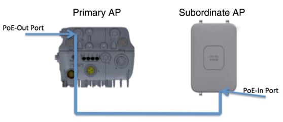
If the primary AP is a 1570 and the subordinate AP is a 1532 or 3700P, the Ethernet cable connects the PoE-Out port of the primary AP to the PoE-In port of the subordinate AP.
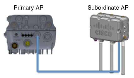
If the primary AP is a 1570 and the subordinate AP is a 1520 or 1550, the Ethernet cable connects the 1572's Ethernet port to any Ethernet port on the 1552.
Serial-Backhaul
The 1572 Daisy-chaining feature can be used to provide a serial-backhaul mesh. The primary MAP has a preferred parent selected as the RAP. The subordinate AP has no preferred parent selected, but is physically connect to the primary AP.
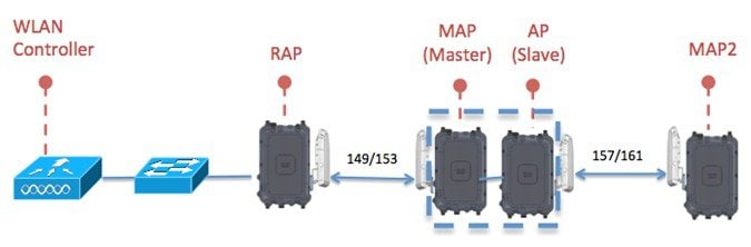
High gain directional antenna should be used in typical serial-backhaul deployments. In addition “Preferred Parent” configurations should be used to create serial-backhaul mesh networks.
The child AP selects the preferred parent based on the following conditions:
-
Preferred parent is the best parent.
-
Preferred parent has a link SNR of at least 20 dB.
-
Preferred parent has a link SNR in the range 12 dB and 20 dB, but no other parent is significantly better (SNR more than 20% is better). For SNR lower than 12 dB, the configuration is ignored.
-
Preferred parent is not in a blocked list.
-
Preferred parent is not in silent mode because of dynamic frequency selection (DFS).
-
Preferred parent is in the same bridge group name (BGN). If the configured preferred parent is not in the same BGN, and no other parent is available, the child will join the parent AP using the default BGN.
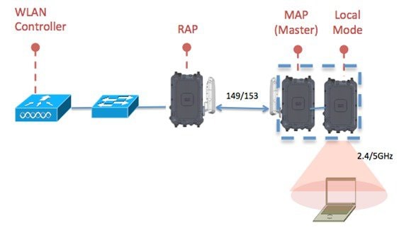
Extended Universal Access
The 1572 Daisy-chaining feature can be used to extend Universal Access across a Mesh network. In this example, the primary MAP is backhauled wirelessly with the RAP. The subordinate AP operates in Local/FlexConnect mode and provides client access on both the 2.4 GHz and 5 GHz radio.
Daisy-chaining between Access Point Models
-
The subordiante AP can be: 1530 / 1550 / 3700P.
-
PoE-Out is 802.11at (25.5w), 1532E / 3702P, and can be powered directly.
-
For PoE-Out, the 1572 power source must be AC / DC / or PoC.
Configuring a Daisy-Chain
There are a few key components to address when configuring a daisy-chaining deployment:
-
Only Mesh Access Points (MAPs) can operate as a daisy chained AP.
-
The uplink daisy-chained AP is considered the primary AP, and the connected AP is considered the subordinate AP.
-
There must be a preferred parent set for each daisy-chained mesh hop. The primary MAP should have a preferred parent.
-
Daisy-chaining must be enabled on the AP, either via WLC GUI, WLC CLI, or AP CLI.
-
Directional antennas should be used when creating a daisy-chain, which guides the mesh tree formation to the customer needs.
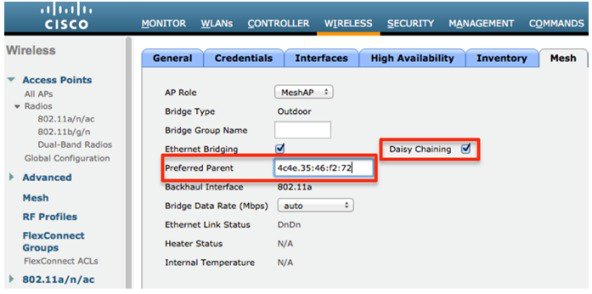
Enabling Daisy-Chaining using the WLC GUI
To enable Daisy-Chaining from the WLC GUI, go to Wireless > Access Point > (AP_NAME) > Mesh, and then check the Daisy-Chaining check box. If the AP is used in a serial-backhaul solution, a Preferred Parent must be selected.
Note |
Daisy-chaining should only be enabled on the slave RAP. The Master MAP should have daisy-chaining as disabled. |
Enabling Daisy-Chaining using the WLC CLI
To enable Daisy-Chaining from the WLC CLI, issue the command:
(Cisco Controller) >config ap daisy-chaining [enable/disable]
                           		  <ap_name>
The daisy chaining feature must be enabled on a per access point basis:
(Cisco Controller) >show ap config general
                           		  <ap_name>
Then scroll down the Daisy Chaining entry
Daisy Chaining ..................................
                           		  Disabled
Enabling Daisy-Chaining using the AP CLI
To enable Daisy-Chaining from the AP CLI, issue the command:
AP#capwap ap daisy-chaining <enable/disable>
Setting a Preferred Parent for each Serial-Backhaul AP
To set up a preferred parent for each serial-backhaul AP, issue the command:
(Cisco Controller) >config
                           		  mesh parent preferred <ap_name> <PARENT_MAC_ADDRESS>
An access point’s preferred parent can be seen by issuing:
(Cisco Controller) >show ap config general <ap_name>
Then scroll down the Mesh preferred parent entry
Mesh preferred parent
                           		  ........................... 00:24:13:0f:92:00
LED Flashing Sequences
The following AP1572 LED behavior notifies users of the status of the Access Point (AP).
|
LED |
Color 1, 2 |
Meaning |
|---|---|---|
|
Status |
Black |
No power applied or LED off. |
|
Steady green |
AP is operational. |
|
|
Blinking green |
Download or upgrade of Cisco IOS image file in progress. |
|
|
Steady amber |
Mesh neighbor access point discovery in progress. |
|
|
Blinking amber |
Mesh authentication in progress. |
|
|
Blinking red / green / amber |
CAPWAP discovery in progress. |
|
|
Steady red |
Firmware failure. Contact your support organization for assistance. |
|
|
Uplink |
Black |
All network ports down or LED off. |
|
Steady green |
Uplink port is operational (cable, fiber optic, or Ethernet). |
|
|
RF-1 |
Black |
Radio turned off or LED off. |
|
Steady green |
Radio is operational; network is good. |
|
|
Steady red |
Firmware failure. Contact your support organization for assistance. |
|
|
RF-2 |
Black |
Radio turned off or LED off. |
|
Steady green |
Radio is operational; network is good. |
|
|
Steady red |
Firmware failure. Contact your support organization for assistance. |
1. If all LEDs off, the AP has no power.
2. When the AP power supply is initially turned on, all LEDs are amber.
Support for Regulatory Domain -B
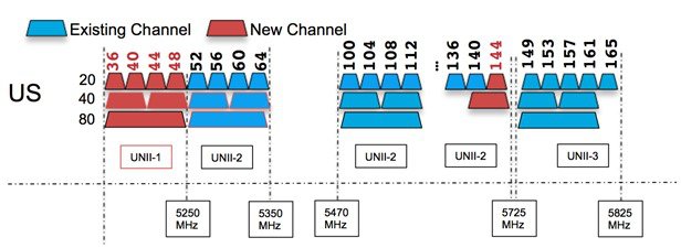
Previously, the Americans have used the -A domain for outdoor access points. The AP1570 provides support for a new -B regulatory domain. The -B regulatory domain allows UNII-1 channels (36-48) and channel 144.
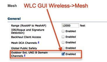
To enable the new –B domain channels, perform the following steps:
-
From the WLC GUI, go to Wireless > Mesh.
-
Check the Outdoor Ext. UNII B Domain Channels check box.
Note |
Checking the check box, and then applying the configuration allows UNII-1 and channel 144 to become selectable. |
AP1570 Coverage Recommendations
The recommended tool for estimating distance and coverage for the AP1570, is the Coverage and Capacity Calculator.
400467.jpg)
This image (2)400467.jpg is not available in preview/cisco.com
Check the Coverage and Capacity Calculator at http://173.37.206.125/aspnet_client/system_web/2_0_50727/wng_coverage_capacity_calculator_v2.0_html/wng_coverage_capacity_calculator_v2.0.htm .
The calculator can be used to estimate AP-to-AP distance. The following table shows a few estimates generated by the calculator for different antenna types.
|
Reg. Domain |
Frequency |
Antenna Gain |
Max. Distance (MCS0LOS) |
High Throughput Distance (2.4 GHz: MCS23, 5 GHz: 80 MHz MCS8-3 LOS) |
|---|---|---|---|---|
|
-A |
2.4 GHz |
6 |
3.3 km |
200 m |
|
5 GHz |
8 |
2.7 km |
30 m | |
|
-E |
2.4 GHz |
6 |
1 km |
30 m |
|
5 GHz |
8 |
1 km |
20 m |
|
|
-A |
2.4 GHz |
13 |
10 km |
335 m |
|
5 GHz |
13 |
3 km |
60 m |
|
|
-E |
2.4 GHz |
13 |
2.5 km |
70 m |
|
5 GHz |
13 |
1.5 km |
30 m |
The following table shows a few distance estimates for an AP1572E to an iPhone client.
|
Reg. Domain |
Frequency |
Antenna Gain |
Max. Distance (MCS0LOS) |
High Throughput Distance (2.4 GHz: MCS23, 5 GHz: 80 MHz MCS9-3 LOS) to iPhone |
|---|---|---|---|---|
|
-A |
2.4 GHz |
6 |
800 m |
140 m |
|
5 GHz |
8 |
160 m |
15 m | |
|
-E |
2.4 GHz |
6 |
280 m |
45 m |
|
5 GHz |
8 |
160 m |
15 m |
|
|
-A |
2.4 GHz |
13 |
1.5 km |
250 m |
|
5 GHz |
13 |
275 m |
25 m |
|
|
-E |
2.4 GHz |
13 |
320 m |
60 m |
|
5 GHz |
13 |
180 m |
20 m |
Note |
These tables contain distance estimates under specific use cases. Refer to the Coverage and Capacity for more detailed information. |
URL Links and Other Resources
This section lists the useful reference materials.
AP 1572 Datasheet
http://www.cisco.com/c/en/us/products/wireless/aironet-1570-series/datasheet-listing.htmlCisco Antenna Reference Guide
http://www.cisco.com/c/en/us/products/collateral/wireless/aironet-antennas-accessories/product_data_sheet09186a008008883b.htmlWhy Buy Cisco Brand Antennas
http://www.cisco.com/en/us/prod/collateral/wireless/ps5678/ps10981/white_paper_c11-671769.pdfUnderstanding Antenna Patterns and their Meaning
http://www.cisco.com/en/us/prod/collateral/wireless/ps7183/ps469/prod_white_paper0900aecd806a1a3e.html8.0 Mesh Deployment Guide
http://www.cisco.com/c/en/us/td/docs/wireless/technology/mesh/8-0/design/guide/mesh80.html Feedback