Information
RAID is an array, or group, of multiple independent physical drives that provide high performance and fault tolerance. A RAID drive group improves input/output (I/O) performance and reliability. The RAID drive group appears to the host computer as a single storage unit or as multiple virtual units. I/O is expedited because several drives can be accessed simultaneously.
RAID drive groups improve data storage reliability and fault tolerance compared to single-drive storage systems. Data loss resulting from a drive failure can be prevented by reconstructing missing data from the remaining drives. RAID improves I/O performance and increases storage subsystem reliability.
RAID levels describe a system for ensuring the availability and redundancy of data stored on large disk subsystems. See RAID Levels, page 1-9 for detailed information about RAID levels. The RAID drive-group components and RAID levels are described in the following sections.
Drive Group
A drive group is a group of physical drives. These drives are managed in partitions known as virtual drives.
Virtual Drive
A virtual drive is a partition in a drive group that is made up of contiguous data segments on the drives. A virtual drive can consist of an entire drive group, more than one entire drive group, a part of a drive group, parts of more than one drive group, or a combination of any two of these conditions.
Disk Striping
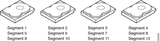
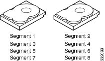
Disk striping (used in RAID level 0) allows you to write data across multiple drives instead of only one drive. Disk striping involves partitioning each drive storage space into stripes that can vary in size from 8 KB to 1024 KB. These stripes are interleaved in a repeated sequential manner. The combined storage space is composed of stripes from each drive. We recommend that you keep stripe sizes the same across RAID drive groups.
For example, in a four-disk system using only disk striping, segment 1 is written to disk 1, segment 2 is written to disk 2, and so on (see Example of Disk Striping (RAID 0)). Disk striping enhances performance because multiple drives are accessed simultaneously, but disk striping does not provide data redundancy
Stripe width is the number of drives involved in a drive group where striping is implemented. For example, a four-disk drive group with disk striping has a stripe width of four.
The stripe size is the length of the interleaved data segments that the RAID controller writes across multiple drives, not including parity drives. For example, consider a stripe that contains 64 KB of disk space and has 16 KB of data residing on each disk in the stripe. In this case, the stripe size is 64 KB and the strip size is 16 KB.
The strip size is the portion of a stripe that resides on a single drive.
Disk Mirroring (RAID 1 and RAID 10)
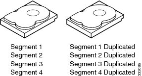
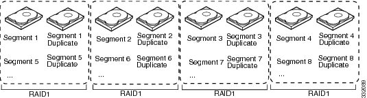
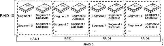
With disk mirroring (used in RAID 1 and RAID 10), data written to one drive is simultaneously written to another drive. The primary advantage of disk mirroring is that it provides 100 percent data redundancy. Because the contents of the disk are completely written to a second disk, data is not lost if one disk fails. In addition, both drives contain the same data at all times, so either disk can act as the operational disk. If one disk fails, the contents of the other disk can be used to run the system and reconstruct the failed disk.
Disk mirroring provides 100 percent redundancy but is expensive because each drive in the system must be duplicated (see Example of Disk Mirroring (RAID 1)).
Parity
Parity generates a set of redundancy data from two or more parent data sets. The redundancy data can be used to reconstruct one of the parent data sets in the event of a drive failure. Parity data does not fully duplicate the parent data sets, but parity generation can slow the write process. In RAID, this method is applied to entire drives or stripes across all of the drives in a drive group. There are two types of parity:
-
Dedicated parity—The parity data on two or more drives is stored on an additional disk.
-
Distributed parity—The parity data is distributed across more than one drive in the system.
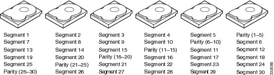
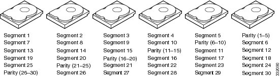
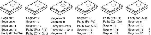
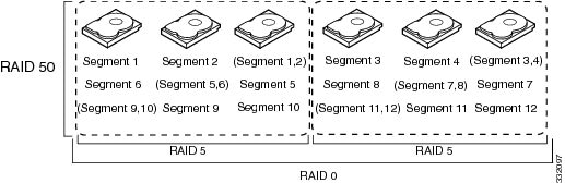
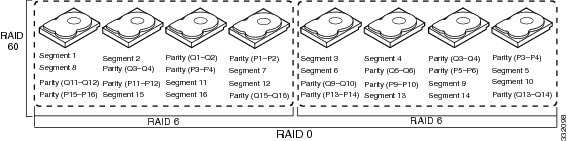
RAID 5 combines distributed parity with disk striping (see Example of Distributed Parity (RAID 5)). If a single drive fails, it can be rebuilt from the parity and the data on the remaining drives. RAID 5 uses parity to provide redundancy for one drive failure without duplicating the contents of entire drives. RAID 6 uses distributed parity and disk striping also but adds a second set of parity data so that it can survive up to two drive failures.
 Note |
Parity is distributed across all drives in the drive group. |
Disk Spanning
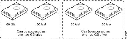
Disk spanning allows multiple drives to function like one big drive. Spanning overcomes lack of disk space and simplifies storage management by combining existing resources or adding relatively inexpensive resources. For example, four 20-GB drives can be combined to appear to the operating system as a single 80-GB drive.
Spanning alone does not provide reliability or performance enhancements. Spanned virtual drives must have the same stripe size and must be contiguous. In Example of Disk Spanning, RAID 1 drive groups are turned into a RAID 10 drive group.
Note |
Make sure that the spans are in different backplanes, so that if one span fails, you do not lose the whole drive group. |
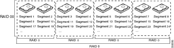
Spanning two contiguous RAID 0 virtual drives does not produce a new RAID level or add fault tolerance. It does increase the capacity of the virtual drive and improves performance by doubling the number of physical disks.
Table 1 describes how to configure RAID 00, RAID 10, RAID 50, and RAID 60 by spanning. The virtual drives must have the same stripe size and the maximum number of spans is eight. The full drive capacity is used when you span virtual drives; you cannot specify a smaller drive capacity.
|
RAID Level |
Description |
||
|---|---|---|---|
|
00 |
Configure RAID 00 by spanning two contiguous RAID 0 virtual drives, up to the maximum number of supported devices for the controller.
|
||
|
10 |
Configure RAID 10 by spanning two contiguous RAID 1 virtual drives, up to the maximum number of supported devices for the controller. RAID 10 supports a maximum of eight spans. You must use an even number of drives in each RAID virtual drive in the span. The RAID 1 virtual drives must have the same stripe size. |
||
|
50 |
Configure RAID 50 by spanning two contiguous RAID 5 virtual drives. The RAID 5 virtual drives must have the same stripe size. |
||
|
60 |
Configure RAID 60 by spanning two contiguous RAID 6 virtual drives. The RAID 6 virtual drives must have the same stripe size. |
Hot Spares
A hot spare is an extra, unused drive that is part of the disk subsystem. It is usually in standby mode, ready for service if a drive fails. If a drive used in a RAID virtual drive fails, a hot spare automatically takes its place and the data on the failed drive is rebuilt on the hot spare. Hot spares can be used for RAID levels 1, 5, 6, 10, 50, and 60.
Hot spares permit you to replace failed drives without system shutdown or user intervention. MegaRAID SAS RAID controllers can implement automatic and transparent rebuilds of failed drives using hot spare drives, providing a high degree of fault tolerance and zero downtime.
Note |
When running RAID 0 and RAID 5 virtual drives on the same set of drives (a sliced configuration), a rebuild to a hot spare cannot occur after a drive failure until the RAID 0 virtual drive is deleted. |
The LSI RAID management software allows you to specify drives as hot spares. When a hot spare is needed, the RAID controller assigns the hot spare that has a capacity closest to and at least as great as that of the failed drive to take the place of the failed drive. The failed drive is removed from the virtual drive and marked ready awaiting removal once the rebuild to a hot spare begins. You can make hot spares of the drives that are not in a RAID virtual drive.
You can use the RAID management software to designate the hot spare to have enclosure affinity, which means that if drive failures are present on a split backplane configuration, the hot spare is used first on the backplane side that it resides in.
If the hot spare is designated as having enclosure affinity, it attempts to rebuild any failed drives on the backplane that it resides in before rebuilding any other drives on other backplanes.
Note |
If a rebuild to a hot spare fails for any reason, the hot spare drive is marked as failed. If the source drive fails, both the source drive and the hot spare drive is marked as failed. |
There are two types of hot spares:
-
Global hot spare
-
Dedicated hot spare
Global Hot Spare
A global hot spare drive can be used to replace any failed drive in a redundant drive group as long as its capacity is equal to or larger than the capacity of the failed drive. A global hot spare defined on any channel should be available to replace a failed drive on both channels.
Dedicated Hot Spare
A dedicated hot spare can be used to replace a failed drive only in a chosen drive group. One or more drives can be designated as a member of a spare drive pool. The most suitable drive from the pool is chosen for failover. A dedicated hot spare is used before one from the global hot spare pool.
Hot spare drives can be located on any RAID channel. Standby hot spares (not being used in RAID drive group) are polled every 60 seconds at a minimum, and their status is made available in the drive group management software. RAID controllers offer the ability to rebuild with a disk that is in a system, but not initially set to be a hot spare.
When using hot spares, observe the following guidelines:
-
Hot spares are used only in drive groups with redundancy, which includes RAID levels 1, 5, 6, 10, 50, and 60.
-
A hot spare connected to a specific RAID controller can be used to rebuild a drive that is connected to the same controller only.
-
You must assign the hot spare to one or more drives through the controller BIOS or use drive group management software to place it in the hot spare pool.
-
A hot spare must have free space equal to or greater than the drive it replaces. For example, to replace an 18-GB drive, the hot spare must be 18 GB or larger.
Disk Rebuilds
When a drive in a RAID drive group fails, you can rebuild the drive by recreating the data that was stored on the drive before it failed. The RAID controller recreates the data using the data stored on the other drives in the drive group. Rebuilding can be done only in drive groups with data redundancy, which includes RAID 1, 5, 6, 10, 50, and 60 drive groups.
The RAID controller uses hot spares to rebuild failed drives automatically and transparently, at user-defined rebuild rates. If a hot spare is available, the rebuild can start automatically when a drive fails. If a hot spare is not available, the failed drive must be replaced with a new drive so that the data on the failed drive can be rebuilt.
The failed drive is removed from the virtual drive and marked ready awaiting removal when the rebuild to a hot spare begins. If the system goes down during a rebuild, the RAID controller automatically restarts the rebuild after the system reboots.
Note |
When the rebuild to a hot spare begins, the failed drive is often removed from the virtual drive before management applications detect the failed drive. When this situation occurs, the events logs show the drive rebuilding to the hot spare without showing the failed drive. The formerly failed drive is marked as ready after a rebuild begins to a hot spare. If a source drive fails during a rebuild to a hot spare, the rebuild fails, and the failed source drive is marked as offline. In addition, the rebuilding hot spare drive is changed back to a hot spare. After a rebuild fails because of a source drive failure, the dedicated hot spare is still dedicated and assigned to the correct drive group, and the global hot spare is still global. |
An automatic drive rebuild does not start if you replace a drive during a RAID-level migration. The rebuild must be started manually after the expansion or migration procedure is complete. (RAID-level migration changes a virtual drive from one RAID level to another.)
Hot Swap
A hot swap is the manual replacement of a defective drive unit while the computer is still running (performing its normal functions). When a new drive is installed, a rebuild occurs automatically if one of the following happens:
-
The newly inserted drive is the same capacity as or larger than the failed drive.
-
It is placed in the same drive bay as the failed drive it is replacing.
The RAID controller can be configured to detect the new drives and rebuild the contents of the drive automatically. The backplane and enclosure must support hot swap for the functionality to work.
Drive States
A drive state is a property that indicates the status of the drive. Table 2 describes the drive states.
|
State |
Description |
||
|---|---|---|---|
|
Online |
A drive that can be accessed by the RAID controller and is part of the virtual drive. |
||
|
Unconfigured Good |
A drive that is functioning normally but is not configured as a part of a virtual drive or as a hot spare. |
||
|
Hot Spare |
A drive that is powered up and ready for use as a spare in case an online drive fails. |
||
|
Failed |
A drive that was originally configured as Online or Hot Spare but on which the firmware detects an unrecoverable error. |
||
|
Rebuild |
A drive to which data is being written to restore full redundancy for a virtual drive. |
||
|
Unconfigured Bad |
A drive on which the firmware detects an unrecoverable error; the drive was Unconfigured Good or the drive could not be initialized. |
||
|
Missing |
A drive that was Online but which has been removed from its location. |
||
|
Offline |
A drive that is part of a virtual drive but which has invalid data as far as the RAID configuration is concerned. When a virtual drive with cached data goes offline, the cache for the virtual drive is discarded. Because the virtual drive is offline, the cache cannot be saved.
|
Virtual Drive States
A virtual drive state is a property indicating the status of the virtual drive. Table 3 describes the virtual drive states.
|
State |
Description |
|---|---|
|
Optimal |
The virtual drive operating condition is good. All configured drives are online. |
|
Degraded |
The virtual drive operating condition is not optimal. One of the configured drives has failed or is offline. |
|
Partial Degraded |
The operating condition in a RAID 6 virtual drive is not optimal. One of the configured drives has failed or is offline. RAID 6 can tolerate up to two drive failures. |
|
Failed |
The virtual drive has failed. |
|
Offline |
The virtual drive is not available to the RAID controller. |
 Feedback