Cisco UCS S3260 Storage Servers with Cohesity DataPlatform
Available Languages
Bias-Free Language
The documentation set for this product strives to use bias-free language. For the purposes of this documentation set, bias-free is defined as language that does not imply discrimination based on age, disability, gender, racial identity, ethnic identity, sexual orientation, socioeconomic status, and intersectionality. Exceptions may be present in the documentation due to language that is hardcoded in the user interfaces of the product software, language used based on RFP documentation, or language that is used by a referenced third-party product. Learn more about how Cisco is using Inclusive Language.
- US/Canada 800-553-2447
- Worldwide Support Phone Numbers
- All Tools
 Feedback
 Feedback

Cisco UCS S3260 Storage Servers with Cohesity DataPlatform
Deployment and Configuration Guide for Cohesity Data Protection on Cisco UCS S3260 M5 Storage Servers for Protection of Cisco HyperFlex, HyperFlex Edge Clusters and File Services
Published: August 2020
In partnership with: ![]()
About the Cisco Validated Design Program
The Cisco Validated Design (CVD) program consists of systems and solutions designed, tested, and documented to facilitate faster, more reliable, and more predictable customer deployments. For more information, go to:
http://www.cisco.com/go/designzone.
ALL DESIGNS, SPECIFICATIONS, STATEMENTS, INFORMATION, AND RECOMMENDATIONS (COLLECTIVELY, "DESIGNS") IN THIS MANUAL ARE PRESENTED "AS IS," WITH ALL FAULTS. CISCO AND ITS SUPPLIERS DISCLAIM ALL WARRANTIES, INCLUDING, WITHOUT LIMITATION, THE WARRANTY OF MERCHANTABILITY, FITNESS FOR A PARTICULAR PURPOSE AND NONINFRINGEMENT OR ARISING FROM A COURSE OF DEALING, USAGE, OR TRADE PRACTICE. IN NO EVENT SHALL CISCO OR ITS SUPPLIERS BE LIABLE FOR ANY INDIRECT, SPECIAL, CONSEQUENTIAL, OR INCIDENTAL DAMAGES, INCLUDING, WITHOUT LIMITATION, LOST PROFITS OR LOSS OR DAMAGE TO DATA ARISING OUT OF THE USE OR INABILITY TO USE THE DESIGNS, EVEN IF CISCO OR ITS SUPPLIERS HAVE BEEN ADVISED OF THE POSSIBILITY OF SUCH DAMAGES.
THE DESIGNS ARE SUBJECT TO CHANGE WITHOUT NOTICE. USERS ARE SOLELY RESPONSIBLE FOR THEIR APPLICATION OF THE DESIGNS. THE DESIGNS DO NOT CONSTITUTE THE TECHNICAL OR OTHER PROFESSIONAL ADVICE OF CISCO, ITS SUPPLIERS OR PARTNERS. USERS SHOULD CONSULT THEIR OWN TECHNICAL ADVISORS BEFORE IMPLEMENTING THE DESIGNS. RESULTS MAY VARY DEPENDING ON FACTORS NOT TESTED BY CISCO.
CCDE, CCENT, Cisco Eos, Cisco Lumin, Cisco Nexus, Cisco StadiumVision, Cisco TelePresence, Cisco WebEx, the Cisco logo, DCE, and Welcome to the Human Network are trademarks; Changing the Way We Work, Live, Play, and Learn and Cisco Store are service marks; and Access Registrar, Aironet, AsyncOS, Bringing the Meeting To You, Catalyst, CCDA, CCDP, CCIE, CCIP, CCNA, CCNP, CCSP, CCVP, Cisco, the Cisco Certified Internetwork Expert logo, Cisco IOS, Cisco Press, Cisco Systems, Cisco Systems Capital, the Cisco Systems logo, Cisco Unified Computing System (Cisco UCS), Cisco UCS B-Series Blade Servers, Cisco UCS C-Series Rack Servers, Cisco UCS S-Series Storage Servers, Cisco UCS Manager, Cisco UCS Management Software, Cisco Unified Fabric, Cisco Application Centric Infrastructure, Cisco Nexus 9000 Series, Cisco Nexus 7000 Series. Cisco Prime Data Center Network Manager, Cisco NX-OS Software, Cisco MDS Series, Cisco Unity, Collaboration Without Limitation, EtherFast, EtherSwitch, Event Center, Fast Step, Follow Me Browsing, FormShare, GigaDrive, HomeLink, Internet Quotient, IOS, iPhone, iQuick Study, LightStream, Linksys, MediaTone, MeetingPlace, MeetingPlace Chime Sound, MGX, Networkers, Networking Academy, Network Registrar, PCNow, PIX, PowerPanels, ProConnect, ScriptShare, SenderBase, SMARTnet, Spectrum Expert, StackWise, The Fastest Way to Increase Your Internet Quotient, TransPath, WebEx, and the WebEx logo are registered trademarks of Cisco Systems, Inc. and/or its affiliates in the United States and certain other countries. (LDW)
All other trademarks mentioned in this document or website are the property of their respective owners. The use of the word partner does not imply a partnership relationship between Cisco and any other company. (0809R)
© 2020 Cisco Systems, Inc. All rights reserved.
Table of Contents
Configuration and Installation
Cohesity Certified Cisco UCS Nodes
Data is the lifeblood of today’s organizations. Yet mass data fragmentation, the continued proliferation of data across different locations, infrastructure silos, clouds, and management systems — has created a divide, preventing enterprises from effectively protecting, managing, and extracting value from the data. The joint Cisco-Cohesity solutions solve mass data fragmentation by converging sprawled latency-sensitive workloads on Cisco HyperFlex and non-latency-sensitive data--backups, archives, file shares, object stores, and data used for dev/test and analytics--on Cohesity DataPlatform. Together, the integrated solutions allow organizations to protect primary data from Cisco HyperFlex and do more with the rest of their data on Cohesity DataPlatform—all on one unified architecture based on Cisco UCS. The joint solutions simplify data management, reduce total cost of ownership (TCO), and mitigate risk.
Cisco HyperFlex systems are based on the Cisco UCS platform, combining Cisco HX-Series x86 servers and integrated networking technologies through the Cisco UCS Fabric Interconnects, into a single management domain, along with various industry leading virtualization hypervisors, and next-generation software defined storage technology. The combination creates a complete modernized hyper-converged virtualization platform, which provides the network connectivity for the guest virtual machine (VM) connections, and the distributed storage to house the VMs, spread across all of the Cisco UCS x86 servers without using specialized storage or networking components.
Cisco HyperFlex Edge managed and deployed through Cisco Intersight, meets the unique challenges of deploying simplified, hyper-converged environments for remote sites with distributed computing at global scale. It incorporates key features optimized to lower cost and reduce space consumption. Customers can choose clusters with two, three, or four HX converged nodes for ease of meeting a wide range of edge-location computing, GPU acceleration, and storage requirements (hot-add additional capacity drives).
This Cisco Validated Design and Deployment Guide provides prescriptive guidance for the design, setup, configuration, and ongoing use of the Cohesity DataPlatform, which in addition to protecting Cisco HyperFlex clusters, provides multi-protocol (NFS/CIFS/S3) file services and object storage capabilities on Cisco UCS S3260 dense storage server. This unique integrated solution is designed to solve siloed infrastructure, operational, and data management challenges faced by enterprises and service providers worldwide. The best-of-breed solution combines the web-scale simplicity and efficiency of Cohesity software with the power and flexibility of Cisco UCS servers. As a result, customers can more efficiently and effectively manage backup and unstructured data growth, acquire new insights, and reduce costs and complexity with a single, integrated solution. For more information on joint Cisco-Cohesity solutions, please see cohesity.com/cisco.
Introduction
The Cisco HyperFlex system combines the industry-leading convergence of computing and networking provided by Cisco UCS, along with next-generation hyper-converged storage software, to uniquely provide the compute resources, network connectivity, storage, and hypervisor platform to run an entire virtual environment; all contained in a single uniform system. Some key advantages of hyper-converged infrastructures are the simplification of deployment, day to day management operations, as well as increased agility, thereby reducing operational costs. Since hyper-converged storage can be easily managed by an IT generalist, this can also reduce technical debt going forward that is often accrued by implementing complex systems that need dedicated management teams and skill sets. The Cisco HyperFlex HX Data Platform is a purpose-built, distributed log-based file system, delivering high-performance, along with many data management and optimization features required in enterprise-class storage systems. This platform offers independent scaling of storage and computing resources, continuous data optimization through in-line compression and deduplication, dynamic data distribution for increased data availability, plus integrated native snapshots, rapid cloning, encryption, and VM and file level replication. This agile system is quick to deploy, easy to manage, is scalable and flexible to adapt to changing workloads, and provides high levels of data security and availability.
Cohesity redefines data management with a web-scale platform that radically simplifies the way companies protect, control and extract value from their data. This software-defined platform spans across core, cloud, and edge, can be managed from a single GUI, and enables independent apps to run in the same environment. It is the only solution built on a hyperconverged, scale-out design that converges backup, files, dev/test, and analytics, and uniquely allows applications to run on the same platform to extract insights from data. Designed with Google-like principles, it delivers true global deduplication and impressive storage efficiency that spans edge to core to the public cloud.
Cohesity running alongside Cisco HyperFlex within a Cisco UCS domain, offers a consolidated system that provides workload hosting, data protection, and file services, all within a single unified architecture. Cohesity and Cisco HyperFlex share complementary datacenter technologies, with both of them utilizing a distributed file system architecture that is designed for high availability. Through a shared-nothing topology, there is no single point of failure or inherent bottlenecks, therefore both performance and capacity can scale linearly as more physical nodes are added to the clusters. The distributed file system spans across all nodes in the cluster and natively provides global deduplication, compression, and encryption. Both systems are deployed on Cisco UCS x86 rack mount server hardware, connected to, and managed by Cisco UCS Fabric Interconnects, which offer stateless, policy-based, programmatic control of the server configurations.
For remote office and branch office (ROBO) deployments, customers can adopt Cohesity’s data management solution either as a virtual appliance or as a physical appliance based on certified Cisco UCS C220 M5 server. Cohesity DataPlatform Virtual Edition (VE) is a virtual appliance-based solution, which aligns perfectly with a Cisco HyperFlex Edge system. Cisco HyperFlex Edge offers a small scale, low cost deployment of the HyperFlex hyper-converged platform for ROBO without the use of Cisco UCS Fabric Interconnects, and instead connects to standard 1 Gigabit or 10 Gigabit Ethernet switches. Cisco Intersight cloud based central management, provides additional advantages for deploying and managing Cisco HyperFlex Edge infrastructures at multiple sites in parallel. Cohesity VE is deployed as a virtual machine within the HyperFlex Edge system, providing local protection of the virtual machines running in the Edge system, and also replicating the snapshots to a larger central Cohesity cluster. Cohesity policies control the retention periods for the local snapshot copies in the Edge system, and also the longer retention of the snapshots in the larger Cohesity clusters. This design allows for both local recovery of single or multiple files and folders and virtual machines, while also providing disaster recovery of all the virtual machines in a ROBO site in case of a total loss or failure.
Besides Protection of HyperFlex Clusters, Cohesity DataPlatform deployed on Cisco UCS C-Series Rack and S-Series systems, provides protection of multiple disparate VMware virtualized environments, bare-metal servers, database clusters, network attached storage (NAS) volumes, and offer file services through NFS, SMB and S3 object storage to enterprises and service providers.
Audience
The intended audience for this document includes, but is not limited to, sales engineers, field consultants, professional services, IT managers, IT engineers, partners, and customers who are interested in learning about and deploying the Cohesity DataPlatform for non-latency-sensitive storage use cases, such as backup & restore, replication, archiving, plus file services with NFS, SMB/CIFS and S3 backed object storage.
Purpose of this Document
This document describes the installation, configuration and use of the Cohesity DataPlatform, Cohesity DataProtect, Cohesity Virtual Edition and Cohesity File Services, protecting VMware ESXi based Cisco HyperFlex systems, including standard clusters and Edge systems. A reference architecture is provided to configure Cohesity DataPlatform on Cisco UCS S Series Storage servers. The document does not specifically explain the design, installation and configuration of the Cisco HyperFlex system, HyperFlex Edge, VMware ESXi, or VMware vCenter, as these are described here: Design Zone for Hyperconverged Infrastructure.
What’s New in this Release?
Unlike VMware snapshots (which uses redo log technology), the Cisco HyperFlex API allows Cohesity to integrate their backup solution with HyperFlex native snapshots. Backup products typically use virtual machine snapshots as a basis for implementing backups. Snapshots are an inherent virtualization feature that saves versions (states) of active virtual machines and can be used in a few scenarios:
· As a local point in time capture that is reversible, as needed. Typically, this is used when a guest OS or application fails.
· To establish a consistent point in time for seeding a backup. By saving the changes made to the virtual machine since the time of the last backup, a new snapshot is analogous to an incremental backup.
· For seeding virtual machine clones and Virtual Desktop solutions.
With Cisco HyperFlex integration, Cohesity DataProtect software takes virtual machine snapshots directly on HyperFlex, which creates a storage-native snapshot for the virtual machine. Since this snapshot is native to HyperFlex, it has very similar performance characteristics as that of the original base disk, when compared to the performance when using standard VMware redo-log based snapshots. After the snapshot is taken, Cohesity DataProtect proceeds to back up the virtual machine data, and once complete the snapshot is deleted through HyperFlex API. Using native snapshots eliminates common delays and I/O penalties and improves application performance by using the underlying HyperFlex distributed storage technology to create and consolidate the snapshots.
Solution Summary
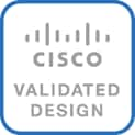
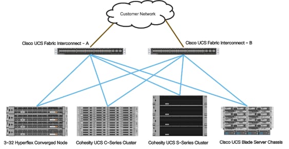
Cohesity DataPlatform on Cisco UCS S3260 Storage Servers, provides modernized, high density platform for reliable data protection for Cisco HyperFlex cluster and Cisco HyperFlex edge clusters deployed on remote sites across geographical regions. In addition to data protection services, customers can leverage file and object services on dense storage provisioned on Cisco UCS S3260 Storage server. The solution extends across the following:
· HyperFlex clusters deployed across data centers and protected with Cohesity DataProtect deployed locally on Cisco UCS S3260 Storage server. Cohesity DataProtect is a licensed feature.
· A minimum of three nodes of Cisco UCS S3260 servers managed through a pair of Cisco Fabric Interconnect 6454.
· HyperFlex Edge cluster deployed across different locations through Cisco Intersight and application VMs on Edge Clusters, protected locally through Cohesity DataPlatform Virtual Edition deployed on HyperFlex Edge data store.
· Replication and Retention of backups through Cohesity Virtual Edition on HyperFlex Edge sites to Cohesity DataPlatform deployed on Cisco UCS S3260 servers residing on Primary Data Center
· Cohesity DataPlatform used for provisioning NFS/CIFS shares for workloads such as video server and file server on Cisco UCS S3260 cluster.
Figure 1 provides a high-level view of various use cases configured and validated in this solution.
Cisco Unified Computing System
Cisco Unified Computing System (Cisco UCS) is a next-generation data center platform that integrates computing, networking, storage access, and virtualization resources into a cohesive system designed to reduce total cost of ownership and increase business agility. The system integrates a low-latency, lossless 10-100 Gigabit Ethernet unified network fabric with enterprise-class, x86-architecture servers. The system is an integrated, scalable, multi-chassis platform with a unified management domain for managing all resources.
Cisco Unified Computing System consists of the following subsystems:
Compute - The compute piece of the system incorporates servers based on the Second-Generation Intel® Xeon® Scalable processors. Servers are available in blade and rack form factor, managed by Cisco UCS Manager.
Network - The integrated network fabric in the system provides a low-latency, lossless, 10/25/40/100 Gbps Ethernet fabric. Networks for LAN, SAN and management access are consolidated within the fabric. The unified fabric uses the innovative Single Connect technology to lowers costs by reducing the number of network adapters, switches, and cables. This in turn lowers the power and cooling needs of the system.
Virtualization - The system unleashes the full potential of virtualization by enhancing the scalability, performance, and operational control of virtual environments. Cisco security, policy enforcement, and diagnostic features are now extended into virtual environments to support evolving business needs.
Storage access – Cisco UCS system provides consolidated access to both SAN storage and Network Attached Storage over the unified fabric. This provides customers with storage choices and investment protection. Also, the server administrators can pre-assign storage-access policies to storage resources, for simplified storage connectivity and management leading to increased productivity.
Management: The system uniquely integrates compute, network, and storage access subsystems, enabling it to be managed as a single entity through Cisco UCS Manager software. Cisco UCS Manager increases IT staff productivity by enabling storage, network, and server administrators to collaborate on Service Profiles that define the desired physical configurations and infrastructure policies for applications. Service Profiles increase business agility by enabling IT to automate and provision resources in minutes instead of days.
Cisco UCS Differentiators
Cisco Unified Computing System is revolutionizing the way servers are managed in the datacenter. The following are the unique differentiators of Cisco Unified Computing System and Cisco UCS Manager:
Embedded Management — In Cisco UCS, the servers are managed by the embedded firmware in the Fabric Interconnects, eliminating the need for any external physical or virtual devices to manage the servers.
Unified Fabric — In Cisco UCS, from blade server chassis or rack servers to FI, there is a single Ethernet cable used for LAN, SAN, and management traffic. This converged I/O results in reduced cables, SFPs and adapters – reducing capital and operational expenses of the overall solution.
Auto Discovery — By simply inserting the blade server in the chassis or connecting the rack server to the fabric interconnect, discovery and inventory of compute resources occurs automatically without any management intervention. The combination of unified fabric and auto-discovery enables the wire-once architecture of Cisco UCS, where compute capability of Cisco UCS can be extended easily while keeping the existing external connectivity to LAN, SAN, and management networks.
Policy Based Resource Classification — Once a compute resource is discovered by Cisco UCS Manager, it can be automatically classified to a given resource pool based on policies defined. This capability is useful in multi-tenant cloud computing. This CVD showcases the policy-based resource classification of Cisco UCS Manager.
Combined Rack and Blade Server Management — Cisco UCS Manager can manage Cisco UCS B-series blade servers and Cisco UCS C-series rack servers under the same Cisco UCS domain. This feature, along with stateless computing makes compute resources truly hardware form factor agnostic.
Model based Management Architecture — The Cisco UCS Manager architecture and management database is model based, and data driven. An open XML API is provided to operate on the management model. This enables easy and scalable integration of Cisco UCS Manager with other management systems.
Policies, Pools, Templates — The management approach in Cisco UCS Manager is based on defining policies, pools, and templates, instead of cluttered configuration, which enables a simple, loosely coupled, data driven approach in managing compute, network, and storage resources.
Loose Referential Integrity — In Cisco UCS Manager, a service profile, port profile or policies can refer to other policies or logical resources with loose referential integrity. A referred policy cannot exist at the time of authoring the referring policy or a referred policy can be deleted even though other policies are referring to it. This provides different subject matter experts to work independently from each other. This provides great flexibility where different experts from different domains, such as network, storage, security, server, and virtualization work together to accomplish a complex task.
Policy Resolution — In Cisco UCS Manager, a tree structure of organizational unit hierarchy can be created that mimics the real-life tenants and/or organization relationships. Various policies, pools and templates can be defined at different levels of organization hierarchy. A policy referring to another policy by name is resolved in the organizational hierarchy with closest policy match. If no policy with specific name is found in the hierarchy of the root organization, then the special policy named “default” is searched. This policy resolution practice enables automation friendly management APIs and provides great flexibility to owners of different organizations.
Service Profiles and Stateless Computing — A service profile is a logical representation of a server, carrying its various identities and policies. This logical server can be assigned to any physical compute resource as far as it meets the resource requirements. Stateless computing enables procurement of a server within minutes, which used to take days in legacy server management systems.
Built-in Multi-Tenancy Support — The combination of policies, pools and templates, loose referential integrity, policy resolution in the organizational hierarchy and a service profiles-based approach to compute resources makes Cisco UCS Manager inherently friendly to multi-tenant environments typically observed in private and public clouds.
Extended Memory — The enterprise-class Cisco UCS Blade server extends the capabilities of the Cisco Unified Computing System portfolio in a half-width blade form factor. It harnesses the power of the latest Intel® Xeon® Scalable Series processor family CPUs and Intel® Optane DC Persistent Memory (DCPMM) with up to 18TB of RAM (using 256GB DDR4 DIMMs and 512GB DCPMM).
Simplified QoS — Even though Fibre Channel and Ethernet are converged in the Cisco UCS fabric, built-in support for QoS and lossless Ethernet makes it seamless. Network Quality of Service (QoS) is simplified in Cisco UCS Manager by representing all system classes in one GUI panel.
Cisco UCS Manager
Cisco UCS Manager (UCSM) provides unified, integrated management for all software and hardware components in Cisco UCS. Using Cisco Single Connect technology, it manages, controls, and administers multiple chassis for thousands of virtual machines. Administrators use the software to manage the entire Cisco Unified Computing System as a single logical entity through an intuitive graphical user interface (GUI), a command-line interface (CLI), or a through a robust application programming interface (API).
Cisco UCS Manager is embedded into the Cisco UCS Fabric Interconnect and provides a unified management interface that integrates server, network, and storage. Cisco UCS Manager performs auto-discovery to detect inventory, manage, and provision system components that are added or changed. It offers a comprehensive set of XML API for third party integration, exposes thousands of integration points, and facilitates custom development for automation, orchestration, and to achieve new levels of system visibility and control.
Cisco UCS™ Manager 4.0 provides unified, embedded management of all software and hardware components of the Cisco Unified Computing System™ (Cisco UCS) across multiple chassis and Cisco UCS servers. Cisco UCS Manager4.0 is a unified software release for all supported Cisco UCS hardware platforms. Release 4.0 enables support for UCS 6454 Fabric Interconnects, VIC 1400 series adapter cards on Cisco UCS M5 servers and Second-Generation Intel® Xeon® Scalable processor refresh and Intel® Optane™ Data Center persistent memory modules on UCS Intel-based M5 servers.
For more information on Cisco UCS Manager Release 4.0 refer to the Release Notes page.
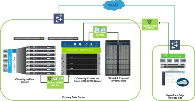
Cisco Intersight
Cisco Intersight™ is a lifecycle management platform for your infrastructure, regardless of where it resides. In your enterprise data center, at the edge, in remote and branch offices, at retail and industrial sites—all these locations present unique management challenges and have typically required separate tools. Cisco Intersight Software as a Service (SaaS) unifies and simplifies your experience of the Cisco Unified Computing System™ (Cisco UCS®) and Cisco HyperFlex™ systems.
Intersight software delivers a new level of cloud-powered intelligence that supports lifecycle management with continuous improvement. It is tightly integrated with the Cisco® Technical Assistance Center (TAC). Expertise and information flow seamlessly between Cisco Intersight and IT teams, providing global management of Cisco infrastructure, anywhere. Remediation and problem resolution are supported with automated upload of error logs for rapid root-cause analysis.
Automate your infrastructure
Cisco has a strong track record for management solutions that deliver policy-based automation to daily operations. Intersight SaaS is a natural evolution of our strategies. Cisco designed Cisco UCS and HyperFlex to be 100 percent programmable. Cisco Intersight simply moves the control plane from the network into the cloud. Now you can manage your Cisco UCS and HyperFlex infrastructure wherever it resides through a single interface.
Deploy your way
If you need to control how your management data is handled, comply with data locality regulations, or consolidate the number of outbound connections from servers, you can use the Cisco Intersight Virtual Appliance for an on-premises experience. Cisco Intersight Virtual Appliance is continuously updated just like the SaaS version, so regardless of which approach you implement, you never have to worry about whether your management software is up to date.
DevOps ready
If you are implementing DevOps practices, you can use the Cisco Intersight API with either the cloud-based or virtual appliance offering. Through the API you can configure and manage infrastructure as code—you are not merely configuring an abstraction layer; you are managing the real thing. Through the API and support of cloud-based RESTful API, Terraform providers, Microsoft PowerShell scripts, or Python software, you can automate the deployment of settings and software for both physical and virtual layers. Using the API, you can simplify infrastructure lifecycle operations and increase the speed of continuous application delivery.
Pervasive simplicity
Simplify the user experience by managing your infrastructure regardless of where it is installed.
Automate updates to Cisco HyperFlex™ Data Platform software, reducing complexity and manual efforts.
Actionable intelligence
Use best practices to enable faster, proactive IT operations.
Gain actionable insight for ongoing improvement and problem avoidance.
Manage anywhere
Deploy in the data center and at the edge with massive scale.
Get visibility into the health and inventory detail for your Intersight Managed environment on-the-go with the Cisco Intersight Mobile App.
For more information about Cisco Intersight and the different deployment options, go to: Cisco Intersight – Manage your systems anywhere.
Cisco UCS Fabric Interconnect
The Cisco UCS Fabric Interconnect (FI) is a core part of the Cisco Unified Computing System, providing both network connectivity and management capabilities for the system. Depending on the model chosen, the Cisco UCS Fabric Interconnect offers line-rate, low-latency, lossless 10 Gigabit, 25 Gigabit, 40 Gigabit, or 100 Gigabit Ethernet, Fibre Channel over Ethernet (FCoE) and Fibre Channel connectivity. Cisco UCS Fabric Interconnects provide the management and communication backbone for the Cisco UCS C-Series, S-Series and HX-Series Rack-Mount Servers, Cisco UCS B-Series Blade Servers, and Cisco UCS 5100 Series Blade Server Chassis. All servers and chassis, and therefore all blades, attached to the Cisco UCS Fabric Interconnects become part of a single, highly available management domain. In addition, by supporting unified fabrics, the Cisco UCS Fabric Interconnects provide both the LAN and SAN connectivity for all servers within its domain.
For networking performance, the Cisco UCS 6454 Series uses a cut-through architecture, supporting deterministic, low latency, line rate 10/25/40/100 Gigabit Ethernet ports, 3.82 Tbps of switching capacity, and 320 Gbps bandwidth per Cisco 5108 blade chassis when connected through the IOM 2208 model. The product family supports Cisco low-latency, lossless 10/25/40/100 Gigabit Ethernet unified network fabric capabilities, which increase the reliability, efficiency, and scalability of Ethernet networks. The Fabric Interconnect supports multiple traffic classes over the Ethernet fabric from the servers to the uplinks. Significant TCO savings come from an FCoE-optimized server design in which network interface cards (NICs), host bus adapters (HBAs), cables, and switches can be consolidated.
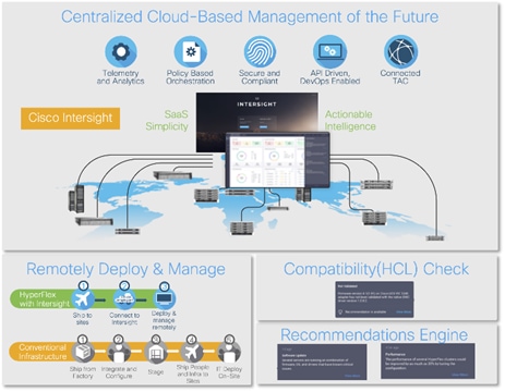
Cisco UCS 6454 Fabric Interconnect
The Cisco UCS 6454 Fabric Interconnect is a one-rack-unit (1RU) 10/25/40/100 Gigabit Ethernet, FCoE and Fiber Channel switch offering up to 3.82 Tbps throughput and up to 54 ports. The switch has eight (8) 10/25-Gbps fixed Ethernet ports, which can optionally be configured as 8/16/32-Gbps FC ports (ports 1 to 8), thirty-six (36) 10/25-Gbps fixed Ethernet ports (ports 9 to 44), four (4) 1/10/25-Gbps Ethernet ports (ports 45 to 48), and finally six (6) 40/100-Gbps Ethernet uplink ports (ports 49 to 54). For more information , please refer Cisco UCS 6454 Fabric Interconnect spec sheet (https://www.cisco.com/c/dam/en/us/products/collateral/servers-unified-computing/ucs-b-series-blade-servers/6400-specsheet.pdf
Cisco UCS S-Series Cohesity-Certified Nodes
The Cisco UCS S3260 Storage Server is a modular, high-density, high-availability dual-node rack server well suited for service providers, enterprises, and industry-specific environments. It addresses the need for dense, cost-effective storage for the ever-growing amounts of data. Designed for a new class of cloud-scale applications and data-intensive workloads, it is simple to deploy and excellent for big data, software-defined storage, and data-protection environments.
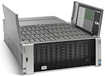
Cisco UCS S3260 is a four-rack-unit (4RU) Storage Server, providing a dense storage platform for cohesity clusters. Each node in the S3260 chassis can be configured with a PCIe-based system I/O controller for Quad Port 10/25G Cisco VIC 1455 or Dual Port 100G Cisco VIC 1495. Cisco S3260 storage server for Cohesity DataPlatform, is equipped with four 3.2 TB high-performance SSD drives for data caching and 21 42 NL-SAS drives, each with 10 TB capacity. For more information, please refer Cisco S3260 storage server spec sheet (https://www.cisco.com/c/dam/en/us/products/collateral/servers-unified-computing/ucs-s-series-storage-servers/s3260-specsheet.pdf)
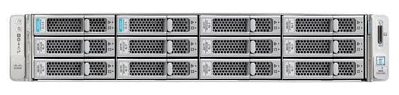
Cisco UCS C-Series Cohesity-Certified Nodes
A Cohesity cluster requires a minimum of three Cisco UCS C-Series nodes (with disk storage). Data is replicated across at least two of these nodes, and a third node is required for continuous operation in the event of a single-node failure. Each node is equipped with two high-performance SSD drives for data caching and rapid acknowledgment of write requests. Each node also is equipped with additional hard disks for long term storage and overall capacity.
Cisco UCS C240 M5 LFF Server
This two-rack-unit (2RU) Cisco C240 M5 Large Form Factor (LFF) model server contains a pair of 240 GB M.2 form factor solid-state disk (SSD) that acts as the boot drives, a pair of 1.6 TB or 3.2 TB NVMe SSD drives installed in the rear drive slots, and twelve 4 TB or 10 TB SATA HDD drives for storage capacity.
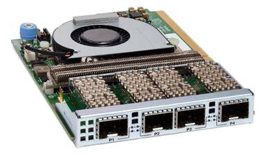
Cisco UCS VIC 1457 MLOM Interface Card
The Cisco UCS VIC 1457 Card is a quad-port Enhanced Small Form-Factor Pluggable (SFP+) 10/25-Gbps Ethernet, and Fibre Channel over Ethernet (FCoE)-capable PCI Express (PCIe) modular LAN-on-motherboard (mLOM) adapter installed in the Cisco UCS C-Series Rack Servers. The VIC 1457 is used in conjunction with the Cisco UCS 6454 model Fabric Interconnects. The mLOM slot can be used to install a Cisco VIC without consuming a PCIe slot, which provides greater I/O expandability. It incorporates next-generation converged network adapter (CNA) technology from Cisco, providing investment protection for future feature releases. The card enables a policy-based, stateless, agile server infrastructure that can present up to 256 PCIe standards-compliant interfaces to the host, each dynamically configured as either a network interface card (NICs) or host bus adapter (HBA). The personality of the interfaces is set programmatically using the service profile associated with the server. The number, type (NIC or HBA), identity (MAC address and Worldwide Name [WWN]), failover policy, adapter settings, bandwidth, and quality-of-service (QoS) policies of the PCIe interfaces are all specified using the service profile.
Cohesity DataPlatform
Cohesity has built a unique solution based on the same architectural principles employed by cloud hyperscalers managing consumer data but optimized for the enterprise world. The secret to the hyperscalers’ success lies in their architectural approach, which has three major components: a distributed file system—a single platform—to store data across locations, a single logical control plane through which to manage it, and the ability to run and expose services atop this platform to provide new functionality through a collection of applications. The Cohesity platform takes this same three-tier hyperscaler architectural approach and adapts it to the specific needs of enterprise data management.
SpanFS: A Unique File System that Powers the Cohesity DataPlatform
The foundation of the Cohesity DataPlatform is Cohesity SpanFS®, a 3rd generation web-scale distributed file system. SpanFS enables the consolidation of all data management services, data, and apps onto a single software-defined platform, eliminating the need for the complex jumble of siloed infrastructure required by the traditional approach.
Predicated on SpanFS, Cohesity DataPlatform’s patented design allows all data management infrastructure functions— including backup and recovery, disaster recovery, long-term archival, file services and object storage, test data management, and analytics—to be run and managed in the same software environment at scale, whether in the public cloud, on-premises, or at the edge. Data is shared rather than siloed, stored efficiently rather than wastefully, and visible rather than kept in the dark—simultaneously addressing the problem of mass data fragmentation while allowing both IT and business teams to holistically leverage its value for the first time. In order to meet modern data management requirements, Cohesity SpanFS provides the following:
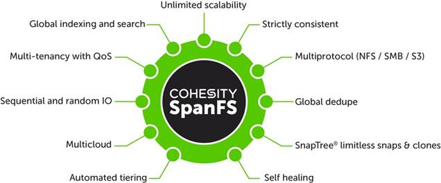
Key SpanFS attributes and implications include the following:
Unlimited Scalability: Start with as little as three nodes and grow limitlessly on-premises or in the cloud with a pay-as-you-grow model.
Strictly Consistent: Ensure data resiliency with strict consistency across nodes within a cluster.
Multi-Protocol: Support traditional NFS and SMB based applications as well as modern S3-based applications. Read and write to the same data volume with simultaneous multiprotocol access.
Global Dedupe: Significantly reduce data footprint by deduplicating across data sources and workloads with global variable-length deduplication.
Unlimited Snapshots and Clones: Create and store an unlimited number of snapshots and clones with significant space savings and no performance impact.
Self-Healing: Auto-balance and auto-distribute workloads across a distributed architecture.
Automated Tiering: Automatic data tiering across SSD, HDD, and cloud storage for achieving the right balance between cost optimization and performance.
Multi Cloud: Native integrations with leading public cloud providers for archival, tiering, replication, and protect cloud-native applications.
Sequential and Random IO: High I/O performance by auto-detecting the IO profile and placing data on the most appropriate media Multitenancy with QoS Native ability to support multiple tenants with QoS support, data isolation, separate encryption keys, and role-based access control.
Global Indexing and Search: Rapid global search due to indexing of file and object metadata.
Requirements
The following sections detail the physical hardware, software revisions, and firmware versions required to install a single cluster of the Cohesity DataPlatform running in Cisco Unified Computing System.
Physical Components
Table 1 Cohesity DataPlatform System Components
| Component |
Hardware Required |
| Fabric Interconnects |
Two (2) Cisco UCS 6454 Fabric Interconnects |
| Servers |
Minimum of three (3) Three Cisco UCS S3260 storage server chassis each with single server node |
Table 2 lists the required hardware components and disk options for the Cisco UCS C240-M5L server model, which are required for installing the Cohesity DataPlatform:
Table 2 Cisco UCS S3260 M5 Chassis Options
| Cisco UCS S3260 M5 options |
Hardware Required |
|
| Chassis |
Cisco UCS S3260 Storage Server Base Chassis |
|
| Server Node |
Cisco UCS S3260 M5 Server Node for Intel Scalable CPUs |
|
| Processors |
Two 2nd Generation Intel Xeon Processor 6240 Scalable Family CPUs |
|
| Memory |
256 GB of total memory using four (8) 32 GB DDR4 2666 MHz 1.2v modules |
|
| Disk Controller |
Cisco UCS S3260 Dual Pass Through based on LSI 3316 |
|
| I/O Expander |
Cisco UCS S3260 I/O Expander for M4/M5 Server Node |
|
| Storage |
SSDs |
4 x Cisco UCS C3000 Top Load 3X 3.2TB SSD |
| HDDs |
42 x 10TB 4Kn NL-SAS drives, or 21 x 10TB 4Kn NL-SAS drives |
|
| Network |
Cisco UCS VIC 1455 Quad Port 10/25G SFP28 CNA PCIE |
|
| Rear Drive / Boot Device |
2 x UCS S3260 240G Boot SSD |
|
Software Components
Table 3 lists the software components and the versions required for a single cluster of the Cohesity DataPlatform running in Cisco UCS, as tested, and validated in this document:
| Component |
Software Required |
| Cohesity DataPlatform, Cohesity DataProtect, Cohesity Helios |
6.3.1c_release-20191209_84f6b398 or later |
| Cisco HyperFlex Data Platform |
Cisco HyperFlex HX Data Platform Software 4.0(1b) or later |
| Cisco UCS Firmware |
Cisco UCS Infrastructure software, B-Series and C-Series bundles, revision 4.0(4i) |
Licensing
Cisco UCS systems and the Cohesity software must be properly licensed for all software features in use, and for all ports in use on the Cisco UCS Fabric Interconnects. Please contact your resale partner or your direct Cisco and Cohesity sales teams to ensure you order all of the necessary and appropriate licenses for your solution.
Physical Topology
Topology Overview
Cisco Unified Computing System is composed of a pair of Cisco UCS Fabric Interconnects along with up to 160 Cisco UCS B-Series blade servers, Cisco UCS C-Series rack-mount servers, HX-Series hyper-converged servers, or S-Series storage servers per UCS domain. Inside of a Cisco UCS domain, multiple environments can be deployed for differing workloads. For example, a Cisco HyperFlex cluster can be built using Cisco HX-Series rack-mount servers, a Cohesity cluster can be built using high density Cisco S-Series Storage server chassis or Cisco UCS C-Series Rack-mount servers and Cisco UCS B-Series blade servers inside of Cisco 5108 blade chassis can be deployed for various bare-metal or virtualized environments. The two Fabric Interconnects both connect to every Cisco UCS C-Series, HX-Series, or Cisco UCS S-Series storage server, and both of them also connect to every Cisco UCS 5108 blade chassis. Upstream network connections, also referred to as “northbound” network connections are made from the Fabric Interconnects to the customer datacenter network at the time of installation.
Fabric Interconnects
Cisco UCS Fabric Interconnects (FI) are deployed in pairs, wherein the two units operate as a management cluster, while forming two separate network fabrics, referred to as the A side and B side fabrics. Therefore, many design elements will refer to FI A or FI B, alternatively called fabric A or fabric B. Both Fabric Interconnects are active at all times, passing data on both network fabrics for a redundant and highly available configuration. Management services, including Cisco UCS Manager, are also provided by the two FIs but in a clustered manner, where one FI is the primary, and one is secondary, with a roaming clustered IP address. This primary/secondary relationship is only for the management cluster and has no effect on data transmission.
Fabric Interconnects have the following ports, which must be connected for proper management of the Cisco UCS domain:
· Mgmt: A 10/100/1000 Mbps port for managing the Fabric Interconnect and the Cisco UCS domain through GUI and CLI tools. This port is also used by remote KVM, IPMI and SoL sessions to the managed servers within the domain. This is typically connected to the customer management network.
· L1: A cross connect port for forming the Cisco UCS management cluster. This port is connected directly to the L1 port of the paired Fabric Interconnect using a standard CAT5 or CAT6 Ethernet cable with RJ45 plugs. It is not necessary to connect this to a switch or hub.
· L2: A cross connect port for forming the Cisco UCS management cluster. This port is connected directly to the L2 port of the paired Fabric Interconnect using a standard CAT5 or CAT6 Ethernet cable with RJ45 plugs. It is not necessary to connect this to a switch or hub.
· Console: An RJ45 serial port for direct console access to the Fabric Interconnect. This port is typically used during the initial FI setup process with the included serial to RJ45 adapter cable. This can also be plugged into a terminal aggregator or remote console server device.
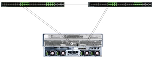
Cisco UCS S-Series Storage Server Chassis
Cohesity UCS clusters require a minimum of three (3) Cisco UCS S Series Storage Server, each equipped with a single Server node. The Cisco UCS S-Series Storage Servers are connected directly to the Cisco UCS Fabric Interconnects in Direct Connect mode. Internally the Cisco UCS S-Series servers are configured with the PCIe-based system I/O controller for Quad Port 10/25G Cisco VIC 1455. The standard and redundant connection practice is to connect port 1 and port 2 of each server’s VIC card to a numbered port on FI A, and port 3 and port 4 of each server’s VIC card to the same numbered port on FI B. The design also supports connecting just port 1 to FI A and port 3 to FI B. The use of ports 1 and 3 are due to the fact that ports 1 and 2 form an internal port-channel, as does ports 3 and 4. This allows an optional 2 cable connection method, which is not used in this design.
![]() WARNING! Failure to follow this cabling practice can lead to errors, discovery failures, and loss of redundant connectivity.
WARNING! Failure to follow this cabling practice can lead to errors, discovery failures, and loss of redundant connectivity.
![]() WARNING! Do not connect port 1 of the VIC 1455 to Fabric Interconnect A, and then connect port 2 of the VIC 1455 to Fabric Interconnect B. Using ports 1 and 2, each connected to FI A and FI B will lead to discovery and configuration failures.
WARNING! Do not connect port 1 of the VIC 1455 to Fabric Interconnect A, and then connect port 2 of the VIC 1455 to Fabric Interconnect B. Using ports 1 and 2, each connected to FI A and FI B will lead to discovery and configuration failures.
Logical Topology
Logical Network Design
The Cohesity DataPlatform running on Cisco UCS has communication pathways that fall into two defined zones:
Management Zone: This zone comprises the connections needed to manage the physical hardware, and the configuration of the Cisco UCS domain. These interfaces and IP addresses need to be available to all staff who will administer the UCS system, throughout the LAN/WAN. All IP addresses in this zone must be allocated from the same layer 2 (L2) subnet. This zone must provide access to Domain Name System (DNS), Network Time Protocol (NTP) services, and allow communication through HTTP/S and Secure Shell (SSH). In this zone are multiple physical and virtual components:
Fabric Interconnect management ports.
Cisco Intelligent Management Controller (CIMC) management interfaces used by each the rack-mount servers and blades, which answer through the FI management ports.
IPMI access over LAN , allowing cohesity Operation System to obtain information about system hardware health to proactively raise alerts and warnings
Application Zone: This zone comprises the connections used by the Cohesity DataPlatform software and the underlying operating system on the nodes. These interfaces and IP addresses need to be able to communicate with each other at all times for proper operation, and they must be allocated from the same L2 subnet. The VLAN used for Cohesity application traffic must be accessible to/from all environments which will be protected by Cohesity, such as the management interfaces of the Cisco HyperFlex nodes, and also its managing vCenter Server system. This zone must provide access to Domain Name System (DNS), Network Time Protocol (NTP) services, and allow communication through HTTP/S and Secure Shell (SSH). Additionally, clients who will connect to Cohesity for file services must also be able to access this VLAN. Finally, the VLAN must be able to traverse the network uplinks from the Cisco UCS domain, reaching FI A from FI B directly through the northbound switches, and vice-versa. In this zone are multiple components:
A static IP address configured for the underlying Linux operating system of each Cohesity node. Two UCS vNICs are configured per node, one on the A side fabric, and one on the B side fabric. The two interfaces are configured as slave interfaces in a bond within the Linux operating system, using bond mode 1 (active/passive).
A floating virtual IP address (VIP), one per node, that is used by Cohesity for all management, backup, and file services access. The assignment of the addresses is handled by the Cohesity software and will be re-assigned to an available node if any node should fall offline. These floating addresses are all assigned in DNS to a single A record, and the DNS server must respond to queries for that A record using DNS round-robin.

Network Design
Cisco UCS Uplink Connectivity
Cisco UCS network uplinks connect “northbound” from the pair of Cisco UCS Fabric Interconnects to the LAN in the customer datacenter. All Cisco UCS uplinks operate as trunks, carrying multiple 802.1Q VLAN IDs across the uplinks. The default Cisco UCS behavior is to assume that all VLAN IDs defined in the Cisco UCS configuration are eligible to be trunked across all available uplinks.
Cisco UCS Fabric Interconnects appear on the network as a collection of endpoints versus another network switch. Internally, the Fabric Interconnects do not participate in spanning-tree protocol (STP) domains, and the Fabric Interconnects cannot form a network loop, as they are not connected to each other with a layer 2 Ethernet link. All link up/down decisions through STP will be made by the upstream root bridges.
Uplinks need to be connected and active from both Fabric Interconnects. For redundancy, multiple uplinks can be used on each FI, either as 802.3ad Link Aggregation Control Protocol (LACP) port-channels or using individual links. For the best level of performance and redundancy, uplinks can be made as LACP port-channels to multiple upstream Cisco switches using the virtual port channel (vPC) feature. Using vPC uplinks allows all uplinks to be active passing data, plus protects against any individual link failure, and the failure of an upstream switch. Other uplink configurations can be redundant, however spanning-tree protocol loop avoidance may disable links if vPC is not available.
All uplink connectivity methods must allow for traffic to pass from one Fabric Interconnect to the other, or from fabric A to fabric B. There are scenarios where cable, port or link failures would require traffic that normally does not leave the Cisco UCS domain, to now be forced over the Cisco UCS uplinks. Additionally, this traffic flow pattern can be seen briefly during maintenance procedures, such as updating firmware on the Fabric Interconnects, which requires them to be rebooted. The following sections and figures detail several uplink connectivity options.
Single Uplinks to Single Switch
This connection design is susceptible to failures at several points; single uplink failures on either Fabric Interconnect can lead to connectivity losses or functional failures, and the failure of the single uplink switch will cause a complete connectivity outage.
Port Channels to Single Switch
This connection design is now redundant against the loss of a single link but remains susceptible to the failure of the single switch.
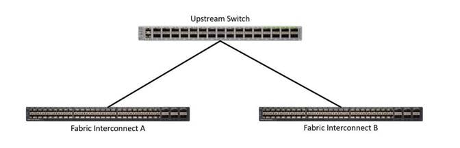
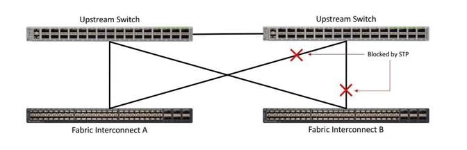
Single Uplinks or Port Channels to Multiple Switches
This connection design is redundant against the failure of an upstream switch, and redundant against a single link failure. In normal operation, STP is likely to block half of the links to avoid a loop across the two upstream switches. The side effect of this is to reduce bandwidth between the Cisco UCS domain and the LAN. If any of the active links were to fail, STP would bring the previously blocked link online to provide access to that Fabric Interconnect through the other switch. It is not recommended to connect both links from a single FI to a single switch, as that configuration is susceptible to a single switch failure breaking connectivity from fabric A to fabric B. For enhanced redundancy, the single links in the figure below could also be port-channels.
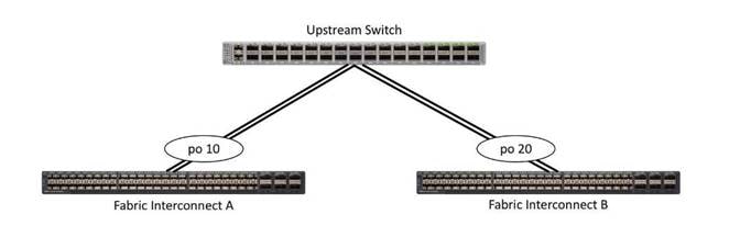
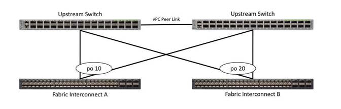
vPC to Multiple Switches
This recommended connection design relies on using Cisco switches that have the virtual port channel feature, such as Catalyst 6000 series switches running VSS, Cisco Nexus 5000 series, and Cisco Nexus 9000 series switches. Logically the two vPC enabled switches appear as one, and therefore spanning-tree protocol will not block any links. This configuration allows for all links to be active, achieving maximum bandwidth potential, and multiple redundancy at each level.
VLANs and Subnets
For the Cohesity system configuration, one only one VLAN is needed to be carried to the Cisco UCS domain from the upstream LAN, and this VLAN is also defined in the Cisco UCS configuration. Table 4 lists the VLANs required by Cohesity in Cisco UCS, and their functions:
| VLAN Name |
VLAN ID |
Purpose |
| <<cohesity_vlan>> |
Customer supplied |
Cohesity node Linux OS interfaces Cohesity node software virtual IP addresses |
Jumbo Frames
All Cohesity traffic traversing the <<cohesity_vlan>> VLAN and subnet is configured by default to use standard ethernet frames.
Considerations
Prior to the installation of the cluster, proper consideration must be given to the number of nodes required for the Cohesity cluster, and the usable capacity that will result.
Scale
Cohesity clusters require a minimum of three (3) Cisco UCS S3260 M5 storage server, each with a single compute node to create an initial cluster. From that point, the cluster can grow to any size of cluster that is required by the end user which meets their overall storage space requirements. This limitless scaling is a key feature present in Cohesity which allows future growth without the fears of reaching an overall capacity restriction. Cohesity Data Platform allows addition of multiple nodes simultaneously.
Capacity
Cohesity provides a configurable resiliency on HDDs or node failures. Both Replication Factor RF2 and RF3 along with the Erasure Coding (EC) scheme is supported with the Cohesity SpanFS filesystem. RF refers to the number of replicas of a unit of data. The unit of replication is a chunk file, and a chunk file is mirrored into either one or two other nodes depending on the RF number chosen. An RF2 mechanism provides resilience against a single data unit failure, and a RF3 provides resilience against two data unit failures.
EC refers to a scheme where a number of usable data stripe units can be protected from failures using code stripe units, which are in turn derived from the usable data stripe units. A single code stripe unit can protect against one data (or code) stripe failure, and two code stripe units can protect against two data (or code) stripe unit failures.
Based on the resiliency and fault tolerance chosen, the raw to usable capacity varies. The figure below provides a high-level understanding of the usable capacity when different types of RF or EC schemes are chosen.
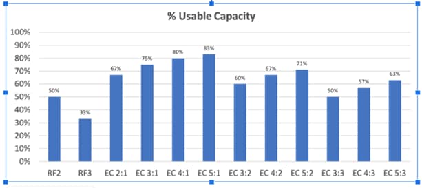
For additional details please see Cohesity resilience white paper here: (https://info.cohesity.com/Cohesity-Fault-Tolerance-White-Paper.html)
Disk drive manufacturers have adopted a size reporting methodology using calculation by powers of 10, also known as decimal prefix. As an example, a 120 GB disk is listed with a minimum of 120 x 10^9 bytes of usable addressable capacity, or 120 billion bytes. However, many operating systems and file systems report their space based on standard computer binary exponentiation, or calculation by powers of 2, also called binary prefix. In this example, 2^10 or 1024 bytes make up a kilobyte, 2^10 kilobytes make up a megabyte, 2^10 megabytes make up a gigabyte, and 2^10 gigabytes make up a terabyte. As the values increase, the disparity between the two systems of measurement and notation get worse, at the terabyte level, the deviation between a decimal prefix value and a binary prefix value is nearly 10 percent.
The International System of Units (SI) defines values and decimal prefix by powers of 10 as listed in Table 5.
Table 5 SI Unit Values (Decimal Prefix)
| Value |
Symbol |
Name |
| 1000 bytes |
kB |
Kilobyte |
| 1000 kB |
MB |
Megabyte |
| 1000 MB |
GB |
Gigabyte |
| 1000 GB |
TB |
Terabyte |
The International Organization for Standardization (ISO) and the International Electrotechnical Commission (IEC) defines values and binary prefix by powers of 2 in ISO/IEC 80000-13:2008 Clause 4 as listed in Table 6.
Table 6 IEC Unit Values (binary prefix)
| Value |
Symbol |
Name |
| 1024 bytes |
KiB |
Kibibyte |
| 1024 KiB |
MiB |
Mebibyte |
| 1024 MiB |
GiB |
Gibibyte |
| 1024 GiB |
TiB |
Tebibyte |
For the purpose of this document, the decimal prefix numbers are used only for raw disk capacity as listed by the respective manufacturers. For all calculations where raw or usable capacities are shown from the perspective of the Cohesity software, filesystems or operating systems, the binary prefix numbers are used. This is done primarily to show a consistent set of values as seen by the end user from within the Cohesity HTML management dashboard when viewing cluster capacity, allocation, and consumption, and also within most operating systems.
Table 7 lists a set of Cohesity DataPlatform cluster usable capacity values, using binary prefix, for an array of cluster configurations. These values provide an example of the capacity calculations, for determining the appropriate size of Cohesity cluster to initially purchase. Additional savings from deduplication and compression will raise the effective logical capacity far beyond the physical capacity of the nodes. Additionally, the choice of replication factor 2, or erasure coding, will determine the overall efficiency of the real data being stored on the nodes.
Table 7 Cohesity Cluster Usable Physical Capacities
| Cisco UCS C-Series Server Model |
Capacity Disk Size (each) |
Capacity Disk Quantity (per node) |
Usable Capacity (per node) |
Capacity per node @ RF2 |
Capacity per node with EC 2:1 |
| C240-M5L |
4 TB |
12 |
43.7 TiB |
21.8 TiB |
29.1 TiB |
| 10 TB |
12 |
109.2 TiB |
54.6 TiB |
72.8 TiB |
|
| S3260 M5 |
10 TB |
42 |
382.2 TiB |
191.1 TiB |
254.8 TiB |
| 10 TB |
21 |
191.1 TiB |
95.6 TiB |
127.4 TiB |
Configuration and Installation
Installing the Cohesity DataPlatform system is done through mounting a virtual DVD image to each Cisco UCS S-Series Storage Server node, which is available for download from Cohesity as an ISO file. The installation DVD validates the hardware configuration, installs the Linux operating system, copies the Cohesity software packages, and completes with the nodes ready for their final configuration to form a cluster. Prior to using the installation DVD, the configuration of the Cisco UCS domain, its policies, templates, and service profiles to be associated to the servers must be completed. The following sections will guide you through the prerequisites and manual steps needed to configure Cisco UCS Manager prior to booting the Cohesity installation DVD, the steps to install Cohesity to each node, and how to perform the remaining post-installation tasks to configure the Cohesity cluster. Finally, a basic configuration example is given for configuring Cohesity Storage Domains, Sources, Policies, Protection Jobs, file services Views, and Test/Dev virtual machine services.
The workflow to configure Cisco UCS for Cohesity cluster with the Cisco UCS S3260 Storage server is detailed in the workflow below. This is a one-time process to configure the Cisco UCS Chassis and Server Profiles Templates for Cohesity Cluster, Chassis Profiles and Service Profiles can be instantiated from templates and attached to multiple Cisco UCS S3260 Chassis and server nodes within the same UCS Domain. A Cisco UCS domain allows you to quickly align computing resources in the data center with rapidly changing business requirements. This built-in flexibility is determined by whether you choose to fully implement the stateless computing feature.
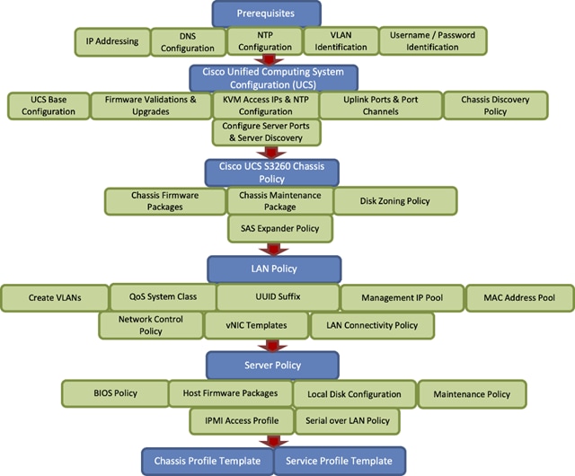
![]() The workflow (Figure 15) to configure the Cisco UCS chassis and server profiles templates for Cohesity Cluster is a one-time process. The chassis profiles and service profiles can be instantiated from templates and attached to multiple Cisco UCS S3260 chassis and server nodes within the same Cisco UCS domain.
The workflow (Figure 15) to configure the Cisco UCS chassis and server profiles templates for Cohesity Cluster is a one-time process. The chassis profiles and service profiles can be instantiated from templates and attached to multiple Cisco UCS S3260 chassis and server nodes within the same Cisco UCS domain.
Prerequisites
Prior to beginning the installation activities, complete the following necessary tasks and gather the required information.
IP Addressing
IP addresses for the Cohesity system on Cisco UCS need to be allocated from the appropriate subnets and VLANs to be used. IP addresses that are used by the system fall into the following groups:
· Cisco UCS Management: These addresses are used and assigned by Cisco UCS Manager. Three IP addresses are used by Cisco UCS Manager; one address is assigned to each Cisco UCS Fabric Interconnect, and the third IP address is a roaming address for management of the Cisco UCS cluster. In addition, at least one IP address per Cisco UCS C-series rack-mount server is required for the Cohesity external management IP address pool, which are assigned to the CIMC interface of the physical servers. Since these management addresses are assigned from a pool, they need to be provided in a contiguous block of addresses. These addresses must all be in the same subnet.
· Cohesity Application: These addresses are used by the Linux OS on each Cohesity node, and the Cohesity software. Two IP addresses per node in the Cohesity cluster are required from the same subnet. These addresses can be assigned from the same subnet at the Cisco UCS Management addresses, or they may be separate.
Use the following tables to list the required IP addresses for the installation of a 4-node standard Cohesity cluster and review an example IP configuration.
![]() Table cells shaded in black do not require an IP address
Table cells shaded in black do not require an IP address
Table 8 Cohesity Cluster IP Addressing
| Address Group: |
UCS Management |
Cohesity Application |
|
| VLAN ID: |
|
|
|
| Subnet: |
|
|
|
| Subnet Mask: |
|
|
|
| Gateway: |
|
|
|
| Device |
UCS Management Addresses |
Node IP |
Cohesity VIP |
| Fabric Interconnect A |
|
|
|
| Fabric Interconnect B |
|
|
|
| UCS Manager |
|
|
|
| Cohesity Node #1 |
|
|
|
| Cohesity Node #2 |
|
|
|
| Cohesity Node #3 |
|
|
|
| Cohesity Node #4 |
|
|
|
Table 9 Example Cohesity Cluster IP Addressing
| Address Group: |
UCS Management |
Cohesity Application |
|
| VLAN ID: |
3171 |
3171 |
|
| Subnet: |
192.168.110.0 |
192.168.110.0 |
|
| Subnet Mask: |
255.255.255.0 |
255.255.255.0 |
|
| Gateway: |
192.168.110.1 |
192.168.110.1 |
|
| Device |
UCS Management Addresses |
Node IP |
Cohesity VIP |
| Fabric Interconnect A |
192.168.110.141 |
|
|
| Fabric Interconnect B |
192.168.110.142 |
|
|
| UCS Manager |
192.168.110.143 |
|
|
| Cohesity Node #1 |
192.168.110.146 |
192.168.110.151 |
192.168.110.155 |
| Cohesity Node #2 |
192.168.110.147 |
192.168.110.152 |
192.168.110.156 |
| Cohesity Node #3 |
192.168.110.148 |
192.168.110.153 |
192.168.110.157 |
| Cohesity Node #4 |
192.168.110.149 |
192.168.110.154 |
192.168.110.158 |
DNS
DNS servers are required to be configured for querying Fully Qualified Domain Names (FQDN) in the Cohesity application group. DNS records need to be created prior to beginning the installation. At a minimum, it is required to create a single A record for the name of the Cohesity cluster, which answers with each of the virtual IP addresses used by the Cohesity nodes in round-robin fashion. Some DNS servers are not configured by default to return multiple addresses in round-robin fashion in response to a request for a single A record, please ensure your DNS server is properly configured for round-robin before continuing. The configuration can be tested by querying the DNS name of the Cohesity cluster from multiple clients and verifying that all of the different IP addresses are given as answers in turn.
Use the following tables to list the required DNS information for the installation and review an example configuration.
Table 10 DNS Server Information
| Item |
Value |
A Records |
| DNS Server #1 |
|
|
| DNS Server #2 |
|
|
| DNS Domain |
|
|
| vCenter Server Name |
|
|
| UCS Domain Name |
|
|
| Cohesity Cluster Name |
|
|
|
|
|
|
|
|
||
|
|
||
Table 11 DNS Server Example Information
| Item |
Value |
A Records |
| DNS Server #1 |
192.168.110.16 |
|
| DNS Server #2 |
|
|
| DNS Domain |
lab151a.cisco.com |
|
| vCenter Server Name |
vcenter.lab151a.cisco.com |
xxx.xxx.xxxx.xxxx |
| UCS Domain Name |
HX1-FI |
|
| Cohesity Cluster Name |
chx-cluster01 |
192.168.110.155 |
|
|
192.168.110.156 |
|
| 192.168.110.157 |
||
| 192.168.110.158 |
||
NTP
Consistent time clock synchronization is required across the components of the Cohesity cluster, provided by reliable NTP servers, accessible for querying in the Cisco UCS Management network group, and the Cohesity Application group. NTP is used by many components, such as Cisco UCS Manager, vCenter, the Cohesity cluster nodes, and the HyperFlex Storage Platform. The use of public NTP servers is highly discouraged, instead a reliable internal NTP server should be used.
Use the following tables to list the required NTP information for the installation and review an example configuration.
Table 12 NTP Server Information
| Item |
Value |
| NTP Server #1 |
|
| NTP Server #2 |
|
| Timezone |
|
Table 13 NTP Server Example Information
| Item |
Value |
| NTP Server #1 |
192.168.110.16 |
| NTP Server #2 |
|
| Timezone |
(UTC-8:00) Pacific Time |
VLANs
Prior to the installation, the required VLAN IDs need to be documented, and created in the upstream network if necessary. There is one VLAN that needs to be trunked to the two Cisco UCS Fabric Interconnects which manage the Cohesity cluster; the VLAN for the Cohesity Application group. The VLAN IDs must be supplied during the Cisco UCS configuration steps, and the VLAN names should be customized to make them easily identifiable.
Use the following tables to list the required VLAN information for the installation and review an example configuration:
| Name |
ID |
| <<cohesity_vlan>> |
|
Table 15 VLAN Example Information
| Name |
ID |
| cohesity-vlan-133 |
3171 |
Network Uplinks
The Cisco UCS uplink connectivity design needs to be finalized prior to beginning the installation. Refer to the network uplink design possibilities in the Network Design section.
Use the following tables to list the required network uplink information for the installation and review an example configuration.
| Fabric Interconnect Port |
Port Channel |
Port Channel Type |
Port Channel ID |
Port Channel Name |
|
| A |
|
☐ Yes ☐ No |
☐ LACP ☐ vPC |
|
|
|
|
☐ Yes ☐ No |
||||
|
|
☐ Yes ☐ No |
||||
|
|
☐ Yes ☐ No |
||||
| B |
|
☐ Yes ☐ No |
☐ LACP ☐ vPC |
|
|
|
|
☐ Yes ☐ No |
||||
|
|
☐ Yes ☐ No |
||||
|
|
☐ Yes ☐ No |
||||
Table 16 Network Uplink Example Configuration
| Fabric Interconnect Port |
Port Channel |
Port Channel Type |
Port Channel ID |
Port Channel Name |
|
| A |
1/53 |
☒ Yes ☐ No |
☐ LACP ☒ vPC |
31 |
vpc31 |
| 1/54 |
☒ Yes ☐ No |
||||
|
|
☐ Yes ☐ No |
||||
|
|
☐ Yes ☐ No |
||||
| B |
1/53 |
☒ Yes ☐ No |
☐ LACP ☒ vPC |
32 |
vpc32 |
| 1/54 |
☒ Yes ☐ No |
||||
|
|
☐ Yes ☐ No |
||||
|
|
☐ Yes ☐ No |
||||
Usernames and Passwords
Several usernames and passwords need to be defined or known as part of the Cohesity installation and configuration process. Use the following tables to list the required username and password information and review an example configuration.
Table 17 Usernames and Passwords
| Account |
Username |
Password |
| UCS Administrator |
admin |
<<ucs_admin_pw>> |
| Cohesity Administrator |
admin |
<<cohesity_admin_pw>> |
| HyperFlex Administrator |
admin |
<<hx_admin_pw>> |
| vCenter Administrator |
<<vcenter_administrator>> |
<<vcenter_admin_pw>> |
Table 18 Example Usernames and Passwords
| Account |
Username |
Password |
| UCS Administrator |
admin |
xxxx |
| Cohesity Administrator |
admin |
xxxx |
| HyperFlex Administrator |
admin |
xxxx |
| vCenter Administrator |
administrator@vsphere.local |
xxxx |
Physical Installation
Install the Fabric Interconnects and the Cisco UCS C-Series rack-mount servers according to their corresponding hardware installation guides listed below:
Cisco UCS 6454 Fabric Interconnect:
https://www.cisco.com/c/en/us/td/docs/unified_computing/ucs/hw/6454-install-guide/6454.pdf
Cisco UCS S Series Storage Server:
https://www.cisco.com/c/dam/en/us/td/docs/unified_computing/ucs/s/hw/S3260/installb/S3260.pdf
Cabling
The physical layout of the Cohesity system was previously described in section Physical Topology. The Fabric Interconnects and C-series rack-mount servers need to be cabled properly before beginning the installation activities.
Table 20 lists an example cabling map for installation of a Cohesity system, using four Cisco UCS C-Series Cohesity converged nodes as tested in this document.
| Device |
Port |
Connected To |
Port |
Type |
Length |
Note |
| UCS6454-A |
L1 |
UCS6454-B |
L1 |
CAT5 |
1FT |
|
| UCS6454-A |
L2 |
UCS6454-B |
L2 |
CAT5 |
1FT |
|
| UCS6454-A |
mgmt0 |
Customer LAN |
|
CAT5 |
|
Management interface |
| UCS6454-A |
1/17 |
Cohesity Chassis #1 |
mLOM port 1 |
Twinax |
3M |
Chassis1/Server2 |
| UCS6454-A |
1/18 |
Cohesity Chassis #1 |
mLOM port 2 |
Twinax |
3M |
Chassis1/Server2 |
| UCS6454-A |
1/19 |
Cohesity Chassis #2 |
mLOM port 1 |
Twinax |
3M |
Chassis2/Server2 |
| UCS6454-A |
1/20 |
Cohesity Chassis #2 |
mLOM port 2 |
Twinax |
3M |
Chassis2/Server2 |
| UCS6454-A |
1/21 |
Cohesity Chassis #3 |
mLOM port 1 |
Twinax |
3M |
Chassis3/Server2 |
| UCS6454-A |
1/22 |
Cohesity Chassis #3 |
mLOM port 2 |
Twinax |
3M |
Chassis3/Server2 |
| UCS6454-A |
1/23 |
Cohesity Chassis #4 |
mLOM port 1 |
Twinax |
3M |
Chassis4/Server2 |
| UCS6454-A |
1/24 |
Cohesity Chassis #4 |
mLOM port 2 |
Twinax |
3M |
Chassis4/Server2 |
| UCS6454-A |
1/53 |
Customer LAN |
|
|
|
uplink |
| UCS6454-A |
1/54 |
Customer LAN |
|
|
|
uplink |
| UCS6454-B |
L1 |
UCS6454-A |
L1 |
CAT5 |
1FT |
|
| UCS6454-B |
L2 |
UCS6454-A |
L2 |
CAT5 |
1FT |
|
| UCS6454-B |
mgmt0 |
Customer LAN |
|
CAT5 |
|
Management interface |
| UCS6454-A |
1/17 |
Cohesity Chassis #1 |
mLOM port 3 |
Twinax |
3M |
Chassis1/Server2 |
| UCS6454-A |
1/18 |
Cohesity Chassis #1 |
mLOM port 4 |
Twinax |
3M |
Chassis1/Server2 |
| UCS6454-A |
1/19 |
Cohesity Chassis #2 |
mLOM port 3 |
Twinax |
3M |
Chassis2/Server2 |
| UCS6454-A |
1/20 |
Cohesity Chassis #2 |
mLOM port 4 |
Twinax |
3M |
Chassis2/Server2 |
| UCS6454-A |
1/21 |
Cohesity Chassis #3 |
mLOM port 3 |
Twinax |
3M |
Chassis3/Server2 |
| UCS6454-A |
1/22 |
Cohesity Chassis #3 |
mLOM port 4 |
Twinax |
3M |
Chassis3/Server2 |
| UCS6454-A |
1/23 |
Cohesity Chassis #4 |
mLOM port 3 |
Twinax |
3M |
Chassis4/Server2 |
| UCS6454-A |
1/24 |
Cohesity Chassis #4 |
mLOM port 4 |
Twinax |
3M |
Chassis4/Server2 |
| UCS6454-B |
1/53 |
Customer LAN |
|
|
|
uplink |
| UCS6454-B |
1/54 |
Customer LAN |
|
|
|
uplink |
Cisco UCS Installation
This section describes the steps to initialize and configure the Cisco UCS Fabric Interconnects, to prepare them for the Cohesity installation. For installations of Cohesity being integrated into an existing Cisco UCS domain, the following steps outlining the initial setup of the Fabric Interconnects, and their uplink port configuration can be skipped. In this situation, the steps beginning with the configuration of the server ports and server discovery onwards, including sub-organizations, policies, pools, templates, and service profiles, must still be performed.
Cisco UCS Fabric Interconnect A
To configure Fabric Interconnect A, follow these steps:
1. Make sure the Fabric Interconnect cabling is properly connected, including the L1 and L2 cluster links, and the management ports, then power the Fabric Interconnects on by inserting the power cords.
2. Connect to the console port on the first Fabric Interconnect, which will be designated as the A fabric device. Use the supplied Cisco console cable (CAB-CONSOLE-RJ45=), and connect it to a built-in DB9 serial port, or use a USB to DB9 serial port adapter.
3. Start your terminal emulator software.
4. Create a connection to the COM port of the computer’s DB9 port, or the USB to serial adapter. Set the terminal emulation to VT100, and the settings to 9600 baud, 8 data bits, no parity, and 1 stop bit.
5. Open the connection which was just created. You may have to press ENTER to see the first prompt.
6. Configure the first Fabric Interconnect, using the following example as a guideline:
---- Basic System Configuration Dialog ----
This setup utility will guide you through the basic configuration of
the system. Only minimal configuration including IP connectivity to
the Fabric interconnect and its clustering mode is performed through these steps.
Type Ctrl-C at any time to abort configuration and reboot system.
To back track or make modifications to already entered values,
complete input till end of section and answer no when prompted
to apply configuration.
Enter the configuration method. (console/gui) ? console
Enter the setup mode; setup newly or restore from backup. (setup/restore) ? setup
You have chosen to setup a new Fabric interconnect. Continue? (y/n): y
Enforce strong password? (y/n) [y]: y
Enter the password for "admin":
Confirm the password for "admin":
Is this Fabric interconnect part of a cluster(select 'no' for standalone)? (yes/no) [n]: yes
Enter the switch fabric (A/B) []: A
Enter the system name: HX1-FI
Physical Switch Mgmt0 IP address : 192.168.110.141
Physical Switch Mgmt0 IPv4 netmask : 255.255.255.0
IPv4 address of the default gateway : 192.168.110.1
Cluster IPv4 address : 192.168.110.143
Configure the DNS Server IP address? (yes/no) [n]: yes
DNS IP address : 192.168.110.16
Configure the default domain name? (yes/no) [n]: yes
Default domain name :
Join centralized management environment (UCS Central)? (yes/no) [n]: no
Following configurations will be applied:
Switch Fabric=A
System Name=HX1-FI
Enforced Strong Password=no
Physical Switch Mgmt0 IP Address=192.168.110.141
Physical Switch Mgmt0 IP Netmask=255.255.255.0
Default Gateway=192.168.110.1
Ipv6 value=0
DNS Server=192.168.110.16
Domain Name=
Cluster Enabled=yes
Cluster IP Address=192.168.110.143
NOTE: Cluster IP will be configured only after both Fabric Interconnects are initialized
Apply and save the configuration (select 'no' if you want to re-enter)? (yes/no): yes
Applying configuration. Please wait.
Configuration file - Ok
Cisco UCS Fabric Interconnect B
To configure Fabric Interconnect B, follow these steps:
1. Connect to the console port on the first Fabric Interconnect, which will be designated as the B fabric device. Use the supplied Cisco console cable (CAB-CONSOLE-RJ45=), and connect it to a built-in DB9 serial port, or use a USB to DB9 serial port adapter.
2. Start your terminal emulator software.
3. Create a connection to the COM port of the computer’s DB9 port, or the USB to serial adapter. Set the terminal emulation to VT100, and the settings to 9600 baud, 8 data bits, no parity, and 1 stop bit.
4. Open the connection which was just created. You may have to press ENTER to see the first prompt.
5. Configure the second Fabric Interconnect, using the following example as a guideline:
---- Basic System Configuration Dialog ----
This setup utility will guide you through the basic configuration of
the system. Only minimal configuration including IP connectivity to
the Fabric interconnect and its clustering mode is performed through these steps.
Type Ctrl-C at any time to abort configuration and reboot system.
To back track or make modifications to already entered values,
complete input till end of section and answer no when prompted
to apply configuration.
Enter the configuration method. (console/gui) ? console
Installer has detected the presence of a peer Fabric interconnect. This Fabric interconnect will be added to the cluster. Continue (y/n) ? y
Enter the admin password of the peer Fabric interconnect:
Connecting to peer Fabric interconnect... done
Retrieving config from peer Fabric interconnect... done
Peer Fabric interconnect Mgmt0 IPv4 Address: 192.168.110.141
Peer Fabric interconnect Mgmt0 IPv4 Netmask: 255.255.255.0
Cluster IPv4 address : 192.168.110.143
Peer FI is IPv4 Cluster enabled. Please Provide Local Fabric Interconnect Mgmt0 IPv4 Address
Physical Switch Mgmt0 IP address : 192.168.110.142
Apply and save the configuration (select 'no' if you want to re-enter)? (yes/no): yes
Applying configuration. Please wait.
Configuration file – Ok
Cisco UCS Manager
To log into the Cisco UCS Manager environment, follow these steps:
1. Open a web browser and navigate to the Cisco UCS Manager Cluster IP address, for example https://192.168.110.143/
2. Click the “Launch UCS Manager” HTML link to open the Cisco UCS Manager web client.
3. At the login prompt, enter “admin” as the username, and enter the administrative password that was set during the initial console configuration.
4. Click No when prompted to enable Cisco Smart Call Home, this feature can be enabled at a later time.
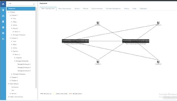
Cisco UCS Configuration
Configure the following ports, settings, and policies in the Cisco UCS Manager interface prior to beginning the Cohesity DataPlatform installation.
Cisco UCS Firmware
Your Cisco UCS firmware version should be current as shipped from the factory, as documented in the Software Components section. This document is based on Cisco UCS infrastructure, Cisco UCS B-series bundle, and Cisco UCS C-Series bundle software versions 4.0(4i). If the firmware version of the Fabric Interconnects is older than this version, the firmware must be upgraded to match the requirements prior to completing any further steps. To upgrade the Cisco UCS Manager version, the Fabric Interconnect firmware, and the server bundles, refer to these instructions:
![]() WARNING! Ensure Host Firmware Package for Cisco UCS S3260 Storage server is no later than 4.04i
WARNING! Ensure Host Firmware Package for Cisco UCS S3260 Storage server is no later than 4.04i
NTP
To synchronize the Cisco UCS environment time to the NTP server, follow these steps:
1. In Cisco UCS Manager, click the Admin button.
2. In the navigation pane, select All > Time Zone Management, and click the carat next to Time Zone Management to expand it.
3. Click Timezone.
4. In the Properties pane, select the appropriate time zone in the Time Zone menu.
5. Click Add NTP Server.
6. Enter the NTP server IP address and click OK.
7. Click OK.
8. Click Save Changes and then click OK.
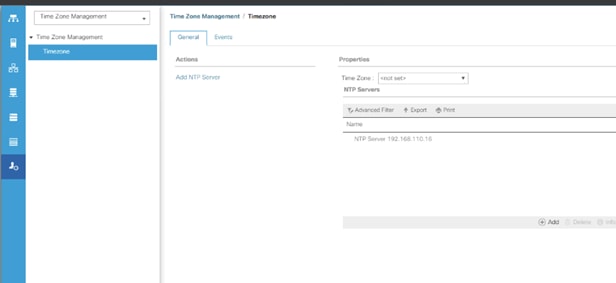
Uplink Ports
The Ethernet ports of a Cisco UCS Fabric Interconnect are all capable of performing several functions, such as network uplinks or server ports, and more. By default, all ports are unconfigured, and their function must be defined by the administrator. To define the specified ports to be used as network uplinks to the upstream network, follow these steps:
1. In Cisco UCS Manager, click Equipment.
2. Select Fabric Interconnects > Fabric Interconnect A > Fixed Module or Expansion Module as appropriate > Ethernet Ports.
3. Select the ports that are to be uplink ports, right-click them, and click Configure as Uplink Port.
4. Click Yes to confirm the configuration and click OK.
5. Select Fabric Interconnects > Fabric Interconnect B > Fixed Module or Expansion Module as appropriate > Ethernet Ports.
6. Select the ports that are to be uplink ports, right-click them, and click Configure as Uplink Port.
7. Click Yes to confirm the configuration and click OK.
8. Verify all the necessary ports are now configured as uplink ports, where their role is listed as “Network.”
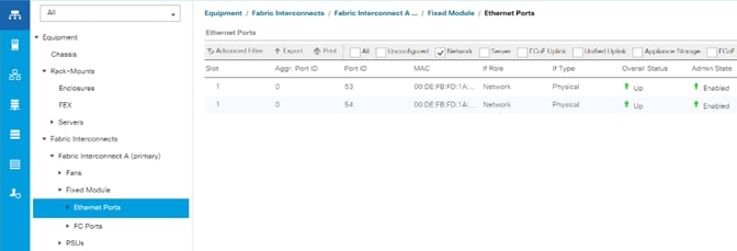
Uplink Port Channels
If the Cisco UCS uplinks from one Fabric Interconnect are to be combined into a port channel or vPC, you must separately configure the port channels, which will use the previously configured uplink ports. To configure the necessary port channels in the Cisco UCS environment, follow these steps:
1. In Cisco UCS Manager, click LAN.
2. Under LAN > LAN Cloud, click the carat to expand the Fabric A tree.
3. Right-click Port Channels underneath Fabric A, then click Create Port Channel.
4. Enter the port channel ID number as the unique ID of the port channel (this does not have to match the port-channel ID on the upstream switch).
5. Enter the name of the port channel.
6. Click Next.
7. Click each port from Fabric Interconnect A that will participate in the port channel and click the >> button to add them to the port channel.
8. Click Finish.
9. Click OK.
10. Under LAN > LAN Cloud, click the carat to expand the Fabric B tree.
11. Right-click Port Channels underneath Fabric B, then click Create Port Channel.
12. Enter the port channel ID number as the unique ID of the port channel (this does not have to match the port-channel ID on the upstream switch).
13. Enter the name of the port channel.
14. Click Next.
15. Click each port from Fabric Interconnect B that will participate in the port channel and click the >> button to add them to the port channel.
16. Click Finish.
17. Click OK.
18. Verify the necessary port channels have been created. It can take a few minutes for the newly formed port channels to converge and come online.
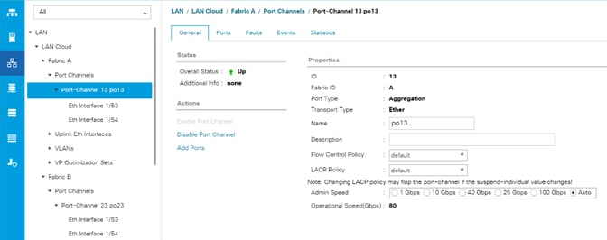
Server Ports
The Ethernet ports of a Cisco UCS Fabric Interconnect connected to the rack-mount servers, or to the blade chassis must be defined as server ports. When a server port is activated, the connected server or chassis will begin the discovery process shortly afterwards. Cisco UCS rack-mount servers and blade chassis are automatically numbered in Cisco UCS Manager in the order which they are first discovered. For this reason, it is important to configure the server ports sequentially in the order you wish the physical servers and/or chassis to appear within Cisco UCS Manager. For example, if you installed your servers in a cabinet or rack with server #1 on the bottom, counting up as you progress higher in the cabinet or rack, then you need to enable the server ports to the bottom-most server first, and enable them one-by-one as you move upward. You must wait until the server appears in the Equipment tab of Cisco UCS Manager before configuring the ports for the next server. The same numbering procedure applies to blade server chassis, although chassis and rack-mount server numbers are separate from each other.
Auto Configuration
A new feature in Cisco UCS Manager 3.1(3a) and later is Server Port Auto-Discovery, which automates the configuration of ports on the Fabric Interconnects as server ports when a Cisco UCS rack-mount server or blade chassis is connected to them. The firmware on the rack-mount servers or blade chassis Fabric Extenders must already be at version 3.1(3a) or later in order for this feature to function properly. Enabling this policy eliminates the manual steps of configuring each server port, however it does configure the servers in a somewhat random order. For example, the rack-mount server at the bottom of the stack, which you may refer to as server 1, and you may have plugged into port 1 of both Fabric Interconnects, could be discovered as server 2, or server 5, and so on.
![]() In order to have fine control of the rack-mount server or chassis numbering and order, the manual configuration steps listed in the next section must be followed.
In order to have fine control of the rack-mount server or chassis numbering and order, the manual configuration steps listed in the next section must be followed.
To configure automatic server port definition and discovery, follow these steps:
1. In Cisco UCS Manager, click Equipment.
2. In the navigation tree, under Policies, click Port Auto-Discovery Policy
3. In the properties pane, set Auto Configure Server Port option to Enabled.
4. Click Save Changes.
5. Click OK.
6. Wait for a brief period, until the rack-mount servers appear in the Equipment tab underneath Equipment > Rack Mounts > Servers, or the chassis appears underneath Equipment > Chassis.
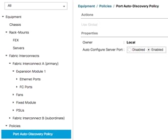
Manual Configuration
To manually define the specified ports to be used as server ports, and have control over the numbering of the servers, follow these steps:
1. In Cisco UCS Manager, click Equipment.
2. Select Fabric Interconnects > Fabric Interconnect A > Fixed Module or Expansion Module as appropriate > Ethernet Ports.
3. Select the first port that is to be a server port, right-click it, and click Configure as Server Port.
4. Click Yes to confirm the configuration and click OK.
5. Select Fabric Interconnects > Fabric Interconnect B > Fixed Module or Expansion Module as appropriate > Ethernet Ports.
6. Select the matching port as chosen for Fabric Interconnect A that is to be a server port, right-click it, and click Configure as Server Port.
7. Click Yes to confirm the configuration and click OK.
8. Wait for a brief period, until the Chassis appears in the Equipment tab underneath Equipment > Chassis.
9. Repeat Steps 1-8 for each pair of server ports, until all rack-mount servers and chassis appear in the order desired in the Equipment tab.
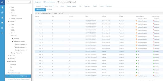
Chassis and Server Discovery
As previously described, when the server ports of the Fabric Interconnects are configured and active, the servers connected to those ports will begin a discovery process. During discovery, the servers’ internal hardware inventories are collected, along with their current firmware revisions. Before continuing with the process of associating the servers with their service profiles, wait for all of the chassis to finish their discovery process and to show as unassociated chassis that are powered off, with no errors.
![]() Ensure the compute node is installed on Slot 2 of the Cisco UCS S3260 chassis.
Ensure the compute node is installed on Slot 2 of the Cisco UCS S3260 chassis.
To view the chassis discovery status, follow these steps:
1. In Cisco UCS Manager, click the Equipment button, then click Equipment in the top of the navigation tree.
2. Click Chassis -> Chassis 1 and ensure that Chassis is discovered.
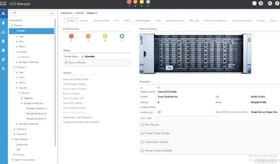
3. Under Chassis-> Chassis <n> -> Servers. Ensure Server node on S3260 Chassis is discovered as Server2. In cohesity deployment on S3260, the server node resides on Server slot 2 of the Chassis. Ensure Server 2 on each Chassis is discovered and is in unassociated state.
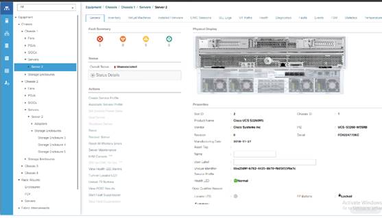
4. Repeat steps 1 - 3 for other chassis which would be configured with Cohesity Cluster.
Cisco UCS Organization
Cisco UCS Manager sub-organizations are created underneath the root level of the Cisco UCS hierarchy, which are used to contain all policies, pools, templates, and service profiles used by the connected servers. Creating a sub-organization specifically for the Cohesity cluster prevents problems from overlapping settings across policies and pools. This arrangement also allows for organizational control using Role-Based Access Control (RBAC) and administrative locales within Cisco UCS Manager at a later time if desired. In this way, control can be granted to administrators of only the Cohesity specific elements of the Cisco UCS domain, separate from control of root level elements or elements in other sub-organizations.
To create a sub-organization for the Cohesity cluster, follow these steps:
1. In Cisco UCS Manager, click Servers.
2. In the tree hierarchy, underneath Servers > Service Profiles, right-click root, then click Create Organization.
3. Enter a name for the organization, for example “Cohesity” and optionally enter a description.
4. Click OK.
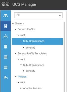
Cisco UCS S3260 Chassis Policies
Create Chassis Firmware Packages
To create Cisco UCS S3260 Chassis Firmware packages, follow these steps:
1. In the Navigation pane, click the Chassis tab.
2. In the Chassis tab, expand Policies > root > sub-Organizations > cohesity.
3. Right-click Chassis Firmware Packages and select Create Chassis Firmware Packages.
4. Enter cohesity_chs_fw as the Package name.
5. From the Chassis Package drop-down list select 4.0(4i)C.
6. Click OK.
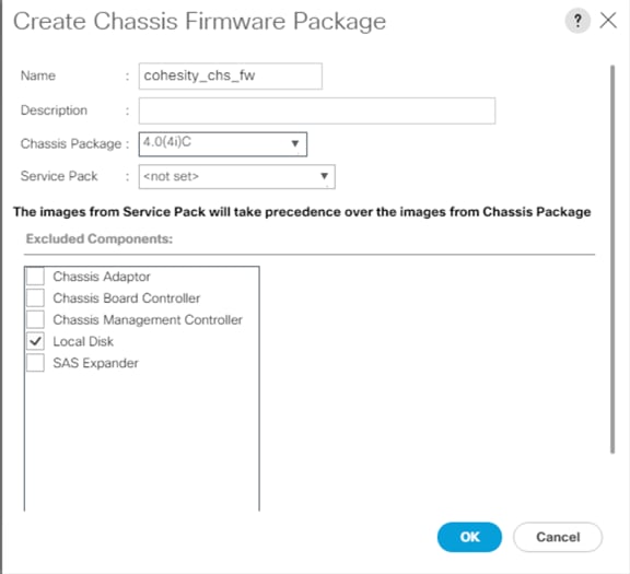
Chassis Maintenance Policies
Cisco UCS Maintenance Policies define the behavior of the attached blades and rack-mount servers when changes are made to the associated service profiles. The default Cisco UCS Maintenance Policy setting is “Immediate” meaning that any change to a service profile that requires a reboot of the chassis will result in an immediate reboot. The Cisco best practice is to use a Maintenance Policy set to “user-ack”, for example, the user must power cycle the chassis manually after the chassis profile association is complete or changes are made.
To configure the Maintenance Policy, follow these steps:
1. In Cisco UCS Manager, click the Chassis button.
2. In the tree hierarchy, underneath Policies > root > Sub-Organizations, click the carat next to the name of the sub-organization created for Cohesity to expand it.
3. Right-click Maintenance Policies, then click Create Maintenance Policy.
4. Enter a name for the policy, and optionally enter a description.
5. Click the radio button for Reboot Policy: User Ack.
6. Click OK.
Figure 17 details the Chassis Maintenance Policy configured for Cohesity.
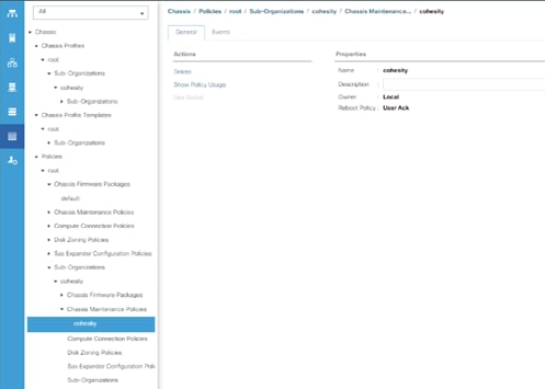
Disk Zoning Policy
You can assign disk drives to the server nodes using disk zoning. Disk zoning can be performed on the controllers in the same server or on the controllers on different servers.
To create Disk Zoning Policy, follow these steps:
1. In the Navigation pane, click Chassis.
2. Expand Policies > root > Sub-Organizations > Cohesity.
3. Right-click Disk Zoning Policies and choose Create Disk Zoning Policy.
4. For the Disk Zone Name, enter cohesity.
5. In the Disk Zoning Information Area, click Add:
a. For Ownership select Dedicated
b. For Server select 2 (the Disk is assigned to node 2 of S3260 Storage server)
c. For Controller select 1
d. For Drive path select 1
e. For Slot range select 1-28
6. Click OK.
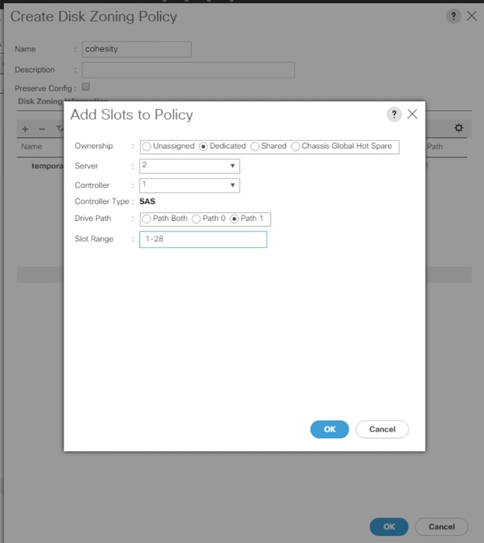
7. Repeat step 5 and add Disk 29-56 and for Controller select 2, and Path 1 and Slot Range 29-56.
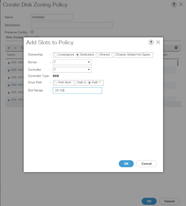
8. Click OK to complete the Disk Zoning Configuration Policy. Disk Zoning policy is displayed below.
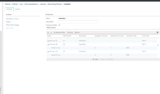
Chassis Sas Expander Configuration Policy
You can assign disk drives to the server nodes using disk zoning. Disk zoning can be performed on the controllers in the same server or on the controllers on different servers.
To create Disk Zoning Policy, follow these steps:
1. In the Navigation pane, click Chassis.
2. Expand Policies > root > Sub-Organizations > Cohesity.
3. Right-click Sas Expander Configuration Policy and click Create.
4. For the name, enter cohesity.
5. For 6G-12G Mixed Mode select Enabled.
6. Click OK.
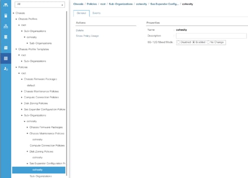
Cisco UCS LAN Policies
VLANs
Names and IDs for the required VLANs must be defined in the Cisco UCS configuration page prior to the Cohesity installation. The VLANs listed in Cisco UCS must already be present on the upstream network, and the Cisco UCS FIs do not participate in VLAN Trunk Protocol (VTP).
To configure the VLAN(s) required for the installation, follow these steps:
1. In Cisco UCS Manager, click LAN..
2. In the tree hierarchy, underneath LAN > LAN Cloud, right-click VLANs, then click Create VLANs.
3. Enter a VLAN name which describes the VLAN purpose.
4. Leave the Multicast Policy Name as <not set>.
5. Choose the radio button for Common/Global.
6. Enter the VLAN ID for this VLAN as defined in the upstream switches.
7. Choose the radio button for Sharing Type: None.
8. Click OK.
Table 20 and Figure 18 detail the VLANs configured for HyperFlex.
| Name |
ID |
Type |
Transport |
Native |
VLAN Sharing |
Multicast Policy |
| <<cohesity-vlan>> |
<user_defined> |
LAN |
Ether |
No |
None |
None |
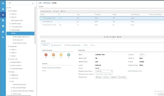
QoS System Classes
By default, Cohesity clusters do not utilize Quality of Service (QoS) policies in their service profiles, and instead place all network traffic into the default “Best-Effort” class. Notably, Cisco HyperFlex clusters are deployed using QoS and a specific configuration for the Cisco UCS QoS System Classes is set during installation. Changes to the Cisco UCS QoS System Classes require a reboot of both Fabric Interconnects. For this reason, if a single UCS domain is intended to contain both Cisco HyperFlex clusters and Cohesity, it is highly recommended to first deploy the Cisco HyperFlex cluster(s). This allows the correct QoS system classes to be set without interrupting service to an existing workload, afterwards Cohesity and other systems can be deployed without any additional impacts.
Create UUID Suffix Pool
A UUID suffix pool is a collection of SMBIOS UUIDs that are available to be assigned to servers. The first number of digits that constitute the prefix of the UUID are fixed. The remaining digits, the UUID suffix, are variable. A UUID suffix pool ensures that these variable values are unique for each server associated with a service profile which uses that particular pool to avoid conflicts.
If you use UUID suffix pools in service profiles, you do not have to manually configure the UUID of the server associated with the service profile.
To configure the necessary universally unique identifier (UUID) suffix pool for the Cisco UCS environment, follow these steps:
1. In Cisco UCS Manager, click the Servers tab in the navigation pane.
2. Select Pools > root > Sub-Organizations >Cohesity.
3. Right-click UUID Suffix Pools.
4. Select Create UUID Suffix Pool.
5. Enter cohesity as the name of the UUID suffix pool.
6. Optional: Enter a description for the UUID suffix pool.
7. Keep the prefix at the derived option.
8. Select Sequential for the Assignment Order.
9. Click Next.
10. Click Add to add a block of UUIDs.
11. Keep the From field at the default setting.
12. Specify a size for the UUID block that is sufficient to support the available server resources.
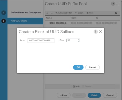
13. Click OK.
14. Click Finish.
15. Click OK.
Management IP Address Pool
A Cisco UCS Management IP Address Pool must be populated with a block of IP addresses. These IP addresses are assigned to the Cisco Integrated Management Controller (CIMC) interface of the rack mount and blade servers that are managed in the Cisco UCS domain. The IP addresses are the communication endpoints for various functions, such as remote KVM, virtual media, Serial over LAN (SoL), and Intelligent Platform Management Interface (IPMI) for each rack mount or blade server. Therefore, a minimum of one IP address per physical server in the domain must be provided. The IP addresses are considered to be an “out-of-band” address, meaning that the communication pathway uses the Fabric Interconnects’ mgmt0 ports, which answer ARP requests for the management addresses. Because of this arrangement, the IP addresses in this pool must be in the same IP subnet as the IP addresses assigned to the Fabric Interconnects’ mgmt0 ports.
To create the management IP address pool, follow these steps:
1. In Cisco UCS Manager, click LAN.
2. In the tree hierarchy, underneath Pools > root > Sub-Organizations, click the carat next to the name of the sub-organization created for Cohesity to expand it.
3. Right-click IP Pools, then click Create IP Pool.
4. Enter a name for the IP address pool, such as “Cohesity”, and optionally enter a description.
5. Click the radio button for Assignment Order: Sequential in order to apply the addresses to the servers in sequence. Choosing Default will result in a random assignment order.
6. Click Next.
7. Click the Add button near the bottom to add a block of IPv4 addresses.
8. Enter the first IP address of the pool in the From: field.
9. Enter the size of the address pool in the Size: field.
10. Enter the correct values for the Subnet Mask, Default Gateway, and Primary and Secondary DNS servers.
11. Click OK.
12. Click Next.
13. In most cases, a pool of IPv6 addresses is not necessary, click Finish.
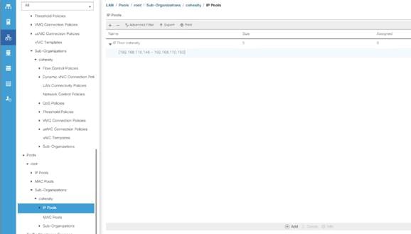
MAC Address Pools
One of the core benefits of the Cisco UCS and Virtual Interface Card (VIC) technology is the assignment of the personality of the card through Cisco UCS Service Profiles. The number of virtual NIC (vNIC) interfaces, their VLAN associations, MAC addresses, QoS policies and more are all applied dynamically as part of the service profile association process. Media Access Control (MAC) addresses use 6 bytes of data as a unique address to identify the interface on the layer 2 network. All devices are assigned a unique MAC address, which is ultimately used for all data transmission and reception. The Cisco UCS and VIC technology picks a MAC address from a pool of addresses and assigns it to each vNIC defined in the service profile when that service profile is created.
Best practices mandate that MAC addresses used for Cisco UCS domains use 00:25:B5 as the first three bytes, which is one of the Organizationally Unique Identifiers (OUI) registered to Cisco Systems, Inc. The remaining 3 bytes can be manually set. The fourth byte (e.g. 00:25:B5:xx) is often used to identify a specific UCS domain, meanwhile the fifth byte is often set to correlate to the Cisco UCS fabric and the vNIC placement order. Finally, the last byte is incremented upward from the starting value defined, according to the number of MAC addresses created in the pool. To avoid overlaps, when you define these values you must ensure that the MAC address pools are unique for each UCS domain installed in the same layer 2 network.
Cohesity servers running inside the Cisco UCS domain require two vNICs, one in the A side fabric, and one in the B side fabric. To make identification and troubleshooting easier, it is recommended to create two MAC address pools; one for the A side fabric vNICs, and a second for the B side fabric vNICs, each with a unique identifier in the fifth byte.
To create the MAC address pools, follow these steps:
1. In Cisco UCS Manager, click LAN.
2. In the tree hierarchy, underneath Pools > root > Sub-Organizations, click the carat next to the name of the sub-organization created for Cohesity to expand it.
3. Right-click MAC Pools, then click Create MAC Pool.
4. Enter a name for the MAC address pool, such as “cohesity-mac-a”, and optionally enter a description.
5. Click the radio button for Assignment Order: Sequential in order to apply the addresses to the servers in sequence. Choosing Default will result in a random assignment order.
6. Click Next.
7. Click Add to add a block of MAC addresses.
8. Modify the values in the 4th byte and 5th byte as necessary in the First MAC Address field. For example, change the field to read “00:25:B5:D0:A1:00”
9. Enter the size of the address pool in the Size: field.
10. Click OK.
11. Click Finish.
12. Repeat steps 1-11 to create any additional MAC address pools required, for example a second pool for the B side vNICs.
Table 21 lists an example of MAC Address Pools configured for Cohesity and their association to the vNIC templates created afterward:
| Name |
Block Start |
Size |
Assignment Order |
Used by vNIC Template |
| cohesity-mac-a |
00:25:B5:D0:A1:00 |
32 |
Sequential |
cohesity-vnic-a |
| cohesity-mac-b |
00:25:B5:D0:B2:00 |
32 |
Sequential |
cohesity-vnic-b |
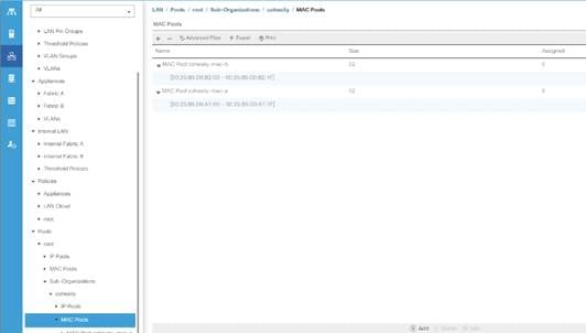
Network Control Policies
Cisco UCS Network Control Policies control various aspects of the behavior of vNICs defined in the Cisco UCS Service Profiles. Settings controlled include enablement of Cisco Discovery Protocol (CDP), MAC address registration, MAC address forging, and the action taken on the vNIC status if the Cisco UCS network uplinks are failed. Of these settings, the most important for the Cohesity DataPlatform is the setting to mark the vNICs as Link Down if there is a failure of all the uplinks from that Fabric Interconnect. This helps ensure that the OS level bonding in the Cohesity nodes will correctly fail over to the other fabric if all uplinks from one FI are lost.
To configure the Network Control Policy, follow these steps:
1. In Cisco UCS Manager, click LAN.
2. In the tree hierarchy, underneath Policies > root > Sub-Organizations, click the carat next to the name of the sub-organization created for Cohesity to expand it.
3. Right-click Network Control Policies, then click Create Network Control Policy.
4. Enter a name for the policy, and optionally enter a description.
5. Click the radio button to set CDP: Enabled.
6. Ensure the setting for Action on Uplink Fail is set to Link Down.
7. All other settings can be left at their defaults.
8. Click OK.
Table 22 lists the Network Control Policy configured for Cohesity, and the assignment to the vNIC templates created:
Table 22 Network Control Policy
| Name |
CDP |
MAC Register Mode |
Action on Uplink Fail |
MAC Security |
Used by vNIC Template |
| cohesity |
Enabled |
Only Native VLAN |
Link-down |
Forged: Allow |
cohesity-vnic-a cohesity-vnic-b |
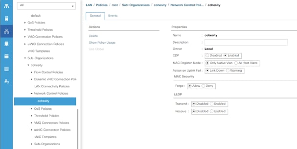
vNIC Templates
Cisco UCS Manager has a feature to configure vNIC templates, which can be used to simplify and speed up configuration efforts. VNIC templates are referenced in service profiles and LAN connectivity policies, versus configuring the same vNICs individually in each service profile, or service profile template. VNIC templates contain all the configuration elements that make up a vNIC, including VLAN assignment, MAC address pool selection, fabric A or B assignment, fabric failover, MTU, QoS policy, Network Control Policy, and more. Templates are created as either initial templates or updating templates. Updating templates retain a link between the parent template and the child object, therefore when changes are made to the template, the changes are propagated to all remaining linked child objects. An additional feature named “vNIC Redundancy” allows vNICs to be configured in pairs, so that the settings of one vNIC template, designated as a primary template, will automatically be applied to a configured secondary template. For all Cohesity vNIC templates, the “A” side vNIC template is configured as a primary template, and the related “B” side vNIC template is a secondary. In each case, the only configuration difference between the two templates is which fabric they are configured to connect through.
To create the vNIC templates, follow these steps:
1. In Cisco UCS Manager, click LAN.
2. In the tree hierarchy, underneath Policies > root > Sub-Organizations, click the carat next to the name of the sub-organization created for Cohesity to expand it.
3. Right-click vNIC Templates, then click Create vNIC Template.
4. Enter a name for the template, and optionally enter a description.
5. Click the radio button for Fabric ID: Fabric A and ensure the checkbox for Enable Failover is left unchecked.
6. Click the radio button for Redundancy Type: Primary Template. Leave the Peer Redundancy Template as <not set>.
7. Leave the Target checkbox for Adapter as checked, and for VM as unchecked.
8. Click the radio button for Template Type: Updating Template.
9. In the list of VLANs, click the checkbox next to the VLAN which was created for Cohesity cluster traffic in order to select it, and click the radio button on the right for Native VLAN in order to pass the traffic without VLAN ID tags.
10. Scroll down in the window, ensure that the CDN source is left as vNIC Name, and the MTU is set to 1500.
11. Choose the MAC Address Pool created earlier for the A side fabric for this vNIC.
12. Choose the Network Control Policy created earlier for this Cohesity sub-organization.
13. Click OK.
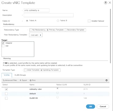
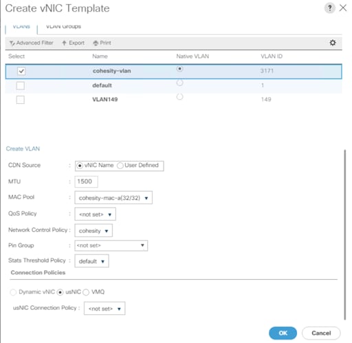
14. Repeat steps 1-13, but doing so for the B side vNIC template, which requires the following changes:
15. Give the template a unique name for the B side template.
16. Choose Fabric B for the Fabric ID.
17. Choose Secondary Template for the Redundancy Type.
18. Choose the vNIC template just created earlier as the Peer Redundancy Template.
19. Choose the MAC Address Pool created earlier for the B side fabric.
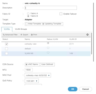
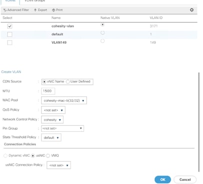
The following tables detail the initial settings in each of the vNIC templates created for the Cohesity DataPlatform:
Table 23 vNIC Template cohesity-vnic-a
| vNIC Template Name: |
vnic-cohesity-a |
|
| Setting |
Value |
|
| Fabric ID |
A |
|
| Fabric Failover |
Disabled |
|
| Target |
Adapter |
|
| Type |
Updating Template |
|
| MTU |
1500 |
|
| MAC Pool |
cohesity-mac-a |
|
| QoS Policy |
<none> |
|
| Network Control Policy |
Cohesity |
|
| VLANs |
<<cohesity-vlan>> |
Native: Yes |
Table 24 vNIC Template cohesity-vnic-b
| vNIC Template Name: |
vnic-cohesity-b |
|
| Setting |
Value |
|
| Fabric ID |
B |
|
| Fabric Failover |
Disabled |
|
| Target |
Adapter |
|
| Type |
Updating Template |
|
| MTU |
1500 |
|
| MAC Pool |
cohesity-mac-b |
|
| QoS Policy |
<none> |
|
| Network Control Policy |
Cohesity |
|
| VLANs |
<<cohesity-vlan>> |
Native: Yes |
| |
|
|
LAN Connectivity Policies
Cisco UCS Manager has a feature for LAN Connectivity Policies, which aggregates all of the vNICs or vNIC templates desired for a service profile configuration into a single policy definition. This simplifies configuration efforts by defining a collection of vNICs or vNIC templates once and using that policy in the service profiles or service profile templates.
To create the LAN Connectivity Policy, follow these steps:
1. In Cisco UCS Manager, click LAN.
2. In the tree hierarchy, underneath Policies > root > Sub-Organizations, click the carat next to the name of the sub-organization created for Cohesity to expand it.
3. Right-click LAN Connectivity Policies, then click Create LAN Connectivity Policy.
4. Enter a name for the policy, and optionally enter a description.
5. Click the Add button near the bottom to add a VNIC.
6. Enter a name for the vNIC being added, for example vNIC0.
7. Click the Use vNIC Template checkbox.
8. In the vNIC Template drop-down box, choose the A side vNIC template created earlier.
9. Click the Redundancy Pair checkbox.
10. In the Peer Name field, enter a name for the redundant vNIC, for example vNIC1.
11. In the Adapter Policy drop-down box, choose the Linux policy.
12. Click OK.
13. Click OK.
The LAN Connectivity Policy is shown below:
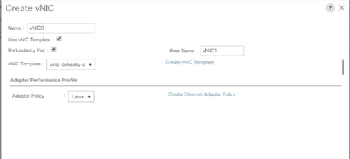
Table 25 lists the LAN Connectivity Policy configured for Cohesity
Table 25 LAN Connectivity Policy
| Policy Name |
Use vNIC Template |
vNIC Name |
vNIC Template Used |
Adapter Policy |
| Cohesity |
Yes |
vNIC0 |
cohesity-vnic-a |
Linux |
| vNIC1 |
cohesity-vnic-b |
Cisco UCS Server Policies
BIOS Policies
Cisco M5 generation servers no longer use predefined BIOS setting defaults derived from Cisco UCS Manager, instead the servers have default BIOS tokens set from the factory. The current default token settings can be found here: Cisco UCS Server BIOS Tokens, Release 4.0.
A BIOS policy must be created to modify the setting of M5 generation servers to enable optimal server performance and Serial over LAN communication, be used during troubleshooting efforts.
For more details on M5 server BIOS settings, please refer Performance Tuning Guide for Cisco UCS M5 Servers White Paper
To configure the BIOS policy, follow these steps:
1. In Cisco UCS Manager, click Servers.
2. In the tree hierarchy, underneath Policies > root > Sub-Organizations, click the carat next to the name of the sub-organization created for Cohesity to expand it.
3. Right-click BIOS Policies, then click Create BIOS Policy.
4. Enter a name for the policy, and optionally enter a description.
5. Click OK.
6. Click the name of the BIOS Policy which was just created.
7. In the right-hand pane of the Cisco UCS Manager screen, click the Advanced tab.
8. Click the Processor tab.
a. For CPU Performance select Enterprise.
b. For Energy Efficient Turbo select Disabled.
c. For Package C State Limit select C0 and C1 state.
d. For Processor C State select Disabled.
e. For Processor EPP Profile select Performance.
f. For Workload Configuration select IO Sensitive.
9. Click the LOM and PCIe Slots tab:
a. For SBMezz1 OptionROM select Disabled.
b. For SBMezz2 OptionROM select Disabled.
10. Click the Serial Port tab:
a. From the Serial Port A drop-down list, select Enabled for the Value.
11. Click the Server Management tab:
a. From the Console Redirection BIOS drop-down list, select Serial Port A.
12. Click Save Changes.
Table 26 lists the BIOS Policy configured for Cohesity.
| Policy Name |
BIOS Tab |
BIOS Sub-Tab |
BIOS Setting |
Value |
| Cohesity |
Advanced |
Processor |
CPU Performance |
Enterprise |
|
|
|
|
Energy Efficient Turbo |
Disabled |
|
|
|
|
Package C State Limit |
C0 C1 State |
|
|
|
|
Processor C State |
Disabled |
|
|
|
|
Processor EPP Profile |
Performance |
|
|
|
|
Workload Configuration |
IO Sensitive |
|
|
Advanced |
Serial Port |
Serial Port A enable |
Enabled |
|
|
Advanced |
LOM and PCIe Slots |
SBMezz1 OptionROM |
Disabled |
|
|
|
|
SBMezz2 OptionROM |
Disabled |
|
|
Server Management |
|
Console Redirection |
Serial Port A |
Boot Policies
Cisco UCS Boot Policies define the boot devices used by blade and rack-mount servers, and the order that they are attempted to boot from. Cisco UCS C-Series M5 generation rack-mount servers which run the Cohesity DataPlatform have their Linux operating system installed to a pair of Rear Boot SSDs, therefore they require a unique boot policy defining that the servers should boot from that location. In addition, a local CD/DVD boot option is included to allow the server to search for the installation ISO media during the Cohesity installation steps.
To configure the Boot Policy, follow these steps:
1. In Cisco UCS Manager, click Servers.
2. In the tree hierarchy, underneath Policies > root > Sub-Organizations, click the carat next to the name of the sub-organization created for Cohesity to expand it.
3. Right-click Boot Policies, then click Create Boot Policy.
4. Enter a name for the template, and optionally enter a description.
5. Leave all settings at their defaults, ensuring the Boot Mode option is set to Legacy.
6. In the Boot Order area, click the + symbol next to Local Devices to expand the list.
7. Click the blue link for “Add CD/DVD”, you will see this selection added to the boot order.
8. Click the blue link for “Add Local Disk.”
9. In the pop-up window, click the radio button for Any, then click OK.
10. Click OK.
The Cohesity Boot Policy is shown below:
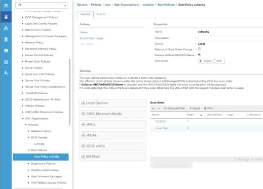
Host Firmware Packages
Cisco UCS Host Firmware Packages represent one of the most powerful features of the Cisco UCS platform; the ability to control the firmware revision of all the managed blades and rack-mount servers through a policy specified in the service profile. Host Firmware Packages are defined and referenced in the service profiles. Once a service profile is associated to a server, the firmware of all the components defined in the Host Firmware Package are automatically upgraded or downgraded to match the package. A Host Firmware Package is created for the Cohesity nodes, which uses the simple package definition method, applying firmware revisions to all components that matches a specific Cisco UCS firmware bundle, versus defining the firmware revision’s part by part.
To configure the Host Firmware Package, follow these steps:
1. In Cisco UCS Manager, click Servers.
2. In the tree hierarchy, underneath Policies > root > Sub-Organizations, click the carat next to the name of the sub-organization created for Cohesity to expand it.
3. Right-click Host Firmware Packages, then click Create Host Firmware Package.
4. Enter a name for the package, and optionally enter a description.
5. Click the radio button for Simple package selection.
6. In the Blade Package and Rack Package drop-down lists, choose the package version that matches the desires firmware version. In most cases, the version chosen would match the currently running Cisco UCS Manager and Fabric Interconnect versions, for example, 4.0(4i)B, and 4.0(4i)C.
7. Choose a Service Pack revision if applicable.
8. Click OK.
The Host Firmware Package used for Cohesity is shown below:
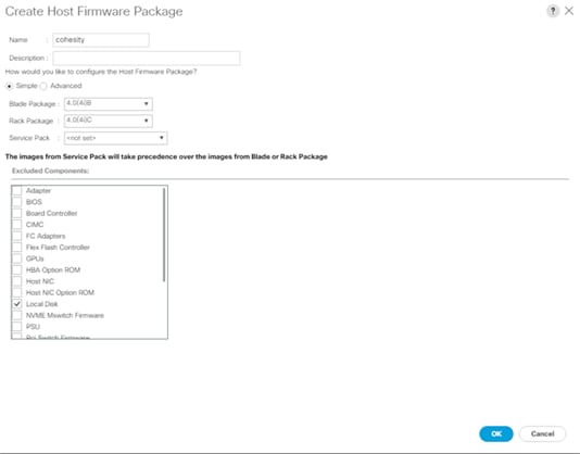
Local Disk Configuration Policies
Cisco UCS Local Disk Configuration Policies are used to define the configuration of disks installed locally within each blade or rack-mount server, most often to configure Redundant Array of Independent/Inexpensive Disks (RAID levels) when multiple disks are present for data protection. Since Cohesity converged nodes providing storage resources utilize software defined storage, the nodes do not require a local disk configuration to be set. Therefore, a simple policy which allows any local disk configuration is all that is required.
To configure the Local Disk Configuration Policy, follow these steps:
1. In Cisco UCS Manager, click Servers.
2. In the tree hierarchy, underneath Policies > root > Sub-Organizations, click the carat next to the name of the sub-organization created for Cohesity to expand it.
3. Right-click Local Disk Config Policies, then click Create Local Disk Configuration Policy.
4. Enter a name for the policy, and optionally enter a description.
5. Leave all options at their default settings, ensuring the Mode drop-down list is set to “Any Configuration”.
6. Click OK.
The Local Disk Configuration Policies configured for cohesity is shown below:
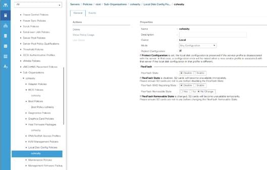
Maintenance Policies
Cisco UCS Maintenance Policies define the behavior of the attached blades and rack-mount servers when changes are made to the associated service profiles. The default Cisco UCS Maintenance Policy setting is “Immediate” meaning that any change to a service profile that requires a reboot of the physical server will result in an immediate reboot of that server. The Cisco best practice is to use a Maintenance Policy set to “user-ack”, which requires a secondary acknowledgement by a user with the appropriate rights within Cisco UCS Manager, before the server is rebooted to apply the changes. In addition, the On Next Boot setting is enabled, which will automatically apply changes the next time the server is rebooted, without any secondary acknowledgement.
To configure the Maintenance Policy, follow these steps:
1. In Cisco UCS Manager, click Servers.
2. In the tree hierarchy, underneath Policies > root > Sub-Organizations, click the carat next to the name of the sub-organization created for Cohesity to expand it.
3. Right-click Maintenance Policies, then click Create Maintenance Policy.
4. Enter a name for the policy, and optionally enter a description.
5. Click the radio button for Reboot Policy: User Ack.
6. Check the checkbox for On Next Boot.
7. Click OK.
The Maintenance Policy configured for Cohesity is shown below:
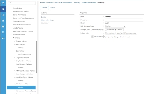
Serial over LAN Policies
Cisco UCS Serial over LAN (SoL) Policies enable console output which is sent to the serial port of the server, to be accessible through the LAN. For many Linux based operating systems, the local serial port can be configured as a local console, where users can watch the system boot, and communicate with the system command prompt interactively. Since many servers do not have physical serial ports, and often administrators are working remotely, the ability to send and receive that traffic through the LAN is very helpful. Interaction with SoL can be initiated by connecting to the CIMC IP address configured by UCS Manager using SSH and entering valid Cisco UCS manager credentials.
To configure the Serial Over LAN Policy, follow these steps:
1. In Cisco UCS Manager, click Servers.
2. In the tree hierarchy, underneath Policies > root > Sub-Organizations, click the carat next to the name of the sub-organization created for Cohesity to expand it.
3. Right-click Serial Over LAN Policies, then click Create Serial Over LAN Policy.
4. Enter a name for the policy, and optionally enter a description.
5. Select the radio button for Serial Over Lan State: Enable
6. Select 115200 from the Speed drop-down list.
7. Click OK.
The SoL Policy configured for Cohesity is shown below:
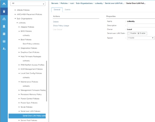
IPMI Access Profile
Cisco UCS Intelligent Platform Management Interface (IPMI) Policies allow for remote interactions with physical hardware resources through the LAN, such as querying power states or forcing servers to power on or off. The Cohesity DataPlatform requires IPMI access to each node and asks for the IPMI addresses and credentials during the installation. Consequently, and IPMI policy is required to enable the functionality through the CIMC interfaces, and to define the username and password which has access to the IPMI commands.
To configure the IPMI Policy, follow these steps:
1. In Cisco UCS Manager, click Servers.
2. In the tree hierarchy, underneath Policies > root > Sub-Organizations, click the carat next to the name of the sub-organization created for Cohesity to expand it.
3. Right-click IPMI Access Profiles, then click Create IPMI Access Profile.
4. Enter a name for the policy, and optionally enter a description.
5. Click the radio button for IPMI Over LAN: Enable.
6. Click Add to create a user.
7. Enter the username.
8. Enter and confirm the desired password.
9. Click the radio button for Role: Admin.
10. Click OK.
11. Click OK.
The IPMI configured for Cohesity is shown below:
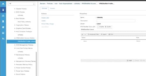
Cisco UCS Chassis Profile Templates
With a chassis profile template, you can quickly create several chassis profiles with the same basic parameters, such as the maintenance policy and the disk zoning policy.
For example, if you need several chassis profiles with similar values, you can create a chassis profile template, either manually or from an existing chassis profile. You can then use the template to create the chassis profiles.
![]() If you need only one chassis profile with similar values to an existing chassis profile, you can clone a chassis profile in the Cisco UCS Manager GUI.
If you need only one chassis profile with similar values to an existing chassis profile, you can clone a chassis profile in the Cisco UCS Manager GUI.
Cisco UCS supports the following types of chassis profile templates:
· Initial template
Chassis profiles created from an initial template inherit all the properties of the template. Chassis profiles created from an initial chassis profile template are bound to the template. However, changes to the initial template do not automatically propagate to the bound chassis profiles. If you want to propagate changes to bound chassis profiles, unbind and rebind the chassis profile to the initial template.
· Updating template
Chassis profiles created from an updating template inherit all the properties of the template and remain connected to the template. Any changes to the template automatically update the chassis profiles created from the template.
To create Chassis Profile Template for Cisco UCS S3260 storage server, follow these steps:
1. In Cisco UCS Manager, click the Chassis tab in the navigation pane.
2. Select Chassis Profile Templates > root > Sub-Organizations > cohesity.
3. Right-click and select Create Chassis Profile Template.
4. Enter name as cohesity-chs-t
5. Select Type as Updating Template.
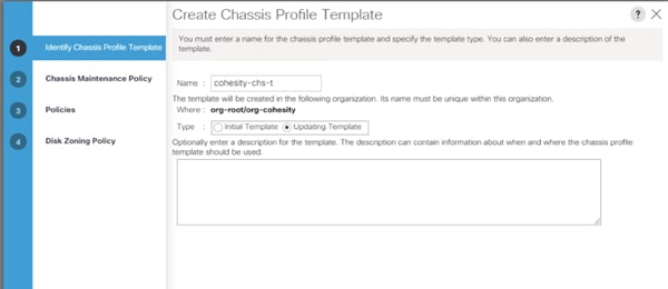
6. Select ‘cohesity’ as the Maintenance Policy and click Next. This maintenance was created under S3260 Chassis Policies
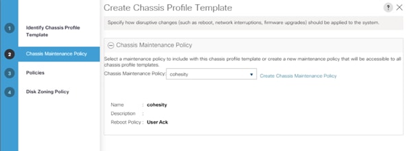
7. Select Chassis Firmware Package as ‘cohesity_chs_fw’ and SAS Expander Policy as ‘cohesity’.
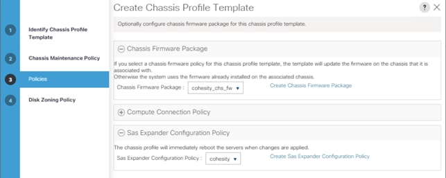
8. Select Disk Zoning Policy as ‘cohesity” and click Finish.
The following table details the chassis profile template configured for the Cohesity DataPlatform chassis:
Table 27 Cisco UCS Chassis Profile Template Settings and Values
| Chassis Profile Template Name: |
Cohesity-chs-t |
| Setting |
Value |
| Chassis Firmware Package |
cohesity_chs_fw |
| Disk Zoning Policy |
cohesity |
| Compute Connection Policy |
<not set> |
| Sas Expander Configuration Policy |
cohesity |
Cisco UCS Service Profile Templates
Cisco UCS Manager has a feature to configure service profile templates, which can be used to simplify and speed up configuration efforts when the same configuration needs to be applied to multiple servers. Service profile templates are used to spawn multiple service profile copies to associate with a group of servers, versus configuring the same service profile manually each time it is needed. Service profile templates contain all the configuration elements that make up a service profile, including vNICs, vHBAs, local disk configurations, boot policies, host firmware packages, BIOS policies and more. Templates are created as either initial templates or updating templates. Updating templates retain a link between the parent template and the child object, therefore when changes are made to the template, the changes are propagated to all remaining linked child objects.
To configure the Service Profile Template, follow these steps:
1. In Cisco UCS Manager, click Servers.
2. In the tree hierarchy, underneath Service Profile Templates > root > Sub-Organizations, click the carat next to the name of the sub-organization created for Cohesity to expand it.
3. Right-click the sub-org name, then click Create Service Profile Template.
4. Enter a name for the template.
5. Click the radio button for Type: Updating Template.
6. In the UUID Assignment drop-down list, select cohesity, created in the previous section.
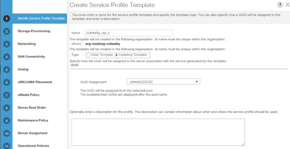
7. Click Next.
8. In the Storage Provisioning section, click the Local Disk Configuration Policy tab, then in the drop-down list below, select the Local Disk Configuration Policy as ‘cohesity’, this was created for this template earlier.
9. Click Next.
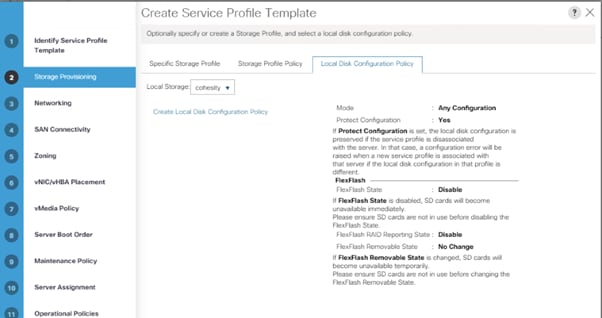
10. In the Networking section, click the radio button for Use Connectivity Policy, then in the drop-down list below, select the LAN Connectivity Policy as ‘cohesity’, this was created for this template earlier.
11. Click Next.
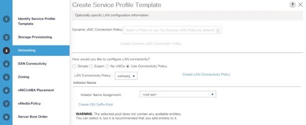
12. In the SAN Connectivity section, click the radio button for No vHBAs, then click Next.
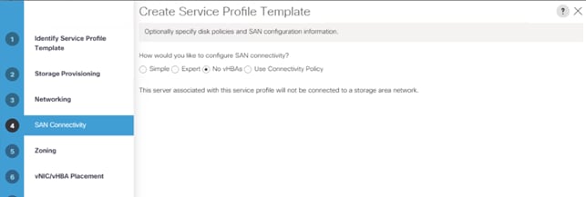
13. In the Zoning section, no changes are required, click Next.
14. In the vNIC/vHBA Placement section, no changes are required, click Next.
15. In the vMedia Policy section, no changes are required, click Next.
16. In the Server Boot Order section, in the Boot Policy drop-down list, select the Boot Policy as ‘cohesity’, this was created for this template earlier.
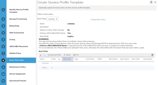
17. Click Next.
18. In the Maintenance Policy section, in the Maintenance Policy drop-down list, select the Maintenance Policy as ‘cohesity’, this was created for this template earlier.
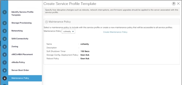
19. Click Next.
20. In the Server Assignment section, leave the Pool Assignment set to Assign Later, and select the radio button for the desired power state to Up.
21. Click the + button next to Firmware Management to expand the section. In the Host Firmware Package drop-down list, select the Host Firmware Package as ‘cohesity’, this was created for this template earlier.
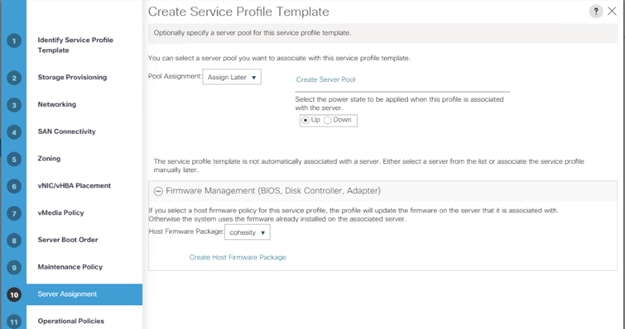
22. Click Next.
23. In the Operation Policies section, click the + button next to BIOS Configuration to expand the section. In the BIOS Policy drop-down list, select the BIOS Policy as ‘cohesity’, this was created for this template earlier.
24. Click the + button next to External IPMI Management Configuration to expand the section. In the IPMI Access Profile drop-down list, select the IPMI Access Profile which was created for this template earlier.
25. In the SoL Configuration Profile drop-down list, select the Serial Over LAN Policy which was created for this template earlier.
26. Click the + button next to Management IP Address to expand the section. Click the Outband IPv4 tab, then from the Management IP Address Policy drop-down list, select the Management IP Address Pool which was created for this template earlier.
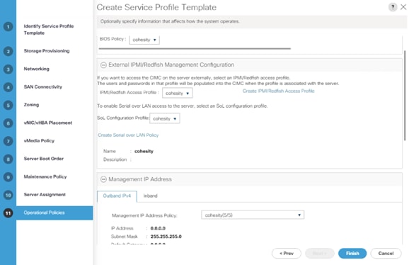
27. Click Finish.
The following table details the service profile template configured for the Cohesity DataPlatform nodes:
Table 28 Cisco UCS Service Profile Template Settings and Values
| Service Profile Template Name: |
Cohesity_sp_t |
| Setting |
Value |
| UUID Pool |
Cohesity |
| Associated Server Pool |
None |
| Maintenance Policy |
Cohesity |
| Management IP Address Policy |
Cohesity |
| Local Disk Configuration Policy |
Cohesity |
| LAN Connectivity Policy |
Cohesity |
| Boot Policy |
Cohesity |
| BIOS Policy |
Cohesity |
| Firmware Policy |
Cohesity |
| Serial over LAN Policy |
Cohesity |
| IPMI Policy |
Cohesity |
Create Chassis Profile
To create chassis profile from the chassis profile template, follow these steps:
28. Click the Chassis tab in the navigation pane.
29. Select Chassis Profile Templates > root > Sub-Organizations > cohesity > Chassis Profile Template Chassis_Template.
30. Right-click Chassis Profile Template cohesity-chs-t and Select Create Chassis Profiles from Template
31. Enter cohesity_chs-p as the Chassis profile prefix.
32. Enter 1 as “Name Suffix Starting Number and 4 as Number of Instances.
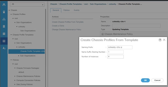
The screenshot below displays four Chassis Profiles, cohesity-chs-p1 to cohesity-chs-p4 under Chassis > root > Sub_organizations > cohesity > Chassis Profile.
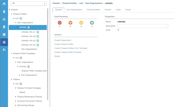
Create Service Profiles
When a Cisco UCS Service Profile Template has been created, individual Service Profiles for each Cohesity node can be created from the template. The unique identifying characteristics of the service profile, such as MAC addresses or IP addresses, are drawn from the pools and the configurations are set according to the policies, when the service profile is created. By basing the service profiles on a template, all of the service profiles will have identical configurations. Because the service profiles are based on an updating template, if any errors are found, or changes need to be made to all of the servers, the changes can be made in the parent template, and all child profiles will inherit the change.
To configure the Service Profiles from the Template, follow these steps:
1. In Cisco UCS Manager, click Servers.
2. In the tree hierarchy, underneath Service Profile Templates > root > Sub-Organizations, click the carat next to the name of the sub-organization created for Cohesity to expand it.
3. Right-click the Service Profile Template, then click Create Service Profiles From Template.
4. Enter a naming prefix, which will be applied to all of the spawned service profiles, for example “Cohesity-node-“
5. Enter the starting number for the number to be appended to the name prefix just entered.
6. Enter the number of service profiles to create from this template.
7. Click OK.
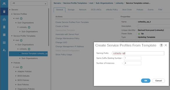
Associate Chassis Profile to Cisco UCS S3260 Chassis
To Associate Chassis Profile to S3260 Chassis, follow these steps:
1. Click the Chassis tab in the navigation pane.
2. Select Chassis Profiles > root > Sub-Organizations > cohesity.
3. Right-click ‘cohesity-chs-p1 and select Change Chassis Profile Association.
4. In the Assignment tab, select Existing Chassis.
5. Select the existing chassis.
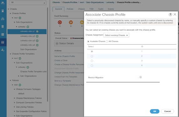
6. Click OK.
7. Since you have selected User Ack for the Maintenance Policy, you need to acknowledge Chassis Reboot for Chassis Profile Association.
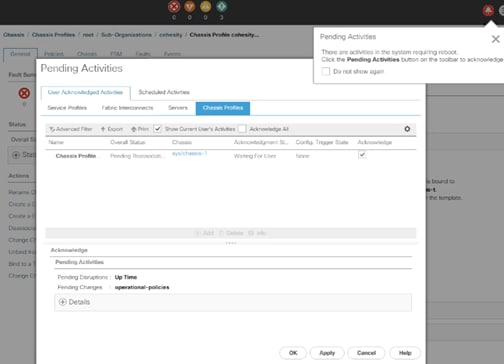
8. On FSM Tab you will see the Association Status.
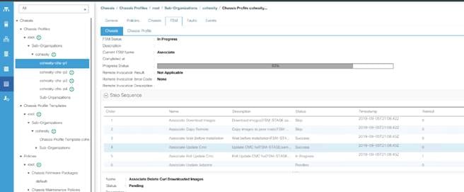
9. When the Chassis is Associated you will see the assigned status as Assigned. Chassis Association may take some time if the firmware of the associated Chassis is not same as the Chassis Firmware Profile attached to the Chassis Profile.
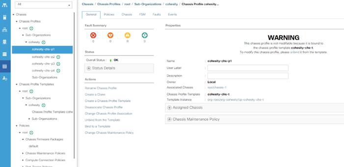
10. Repeat Steps 1-9 for the remaining Chassis available for cohesity cluster deployment.
Service Profile Association
When a Cisco UCS Service Profile has been created, it must be associated with a physical hardware asset in order to take effect. Service profile association requires the server node in the Cisco UCS S3260 storage chassis to be present, fully discovered, and not currently associated with any other service profiles. Automatic assignment of service profiles can be done through the use of server pools and auto-discovery, but that configuration is not the recommended method for this paper, and therefore not covered in this document. Once the service profile association is initiated, all of the configuration elements and identities are applied to the server hardware, including storage, networking, policies, and firmware upgrades. At the conclusion of the association process, the server will be ready for use, but with no operating system installed.
To associate the Service Profiles to the Cohesity node servers, follow these steps:
1. In Cisco UCS Manager, click Servers.
2. In the tree hierarchy, underneath Service Profiles > root > Sub-Organizations, click the carat next to the name of the sub-organization created for Cohesity to expand it.
3. Click the first Service Profile you wish to associate, then in the right-hand pane, click the blue link for “Change Service Profile Association.”
4. In the Server Assignment drop-down list, choose “Select existing Server.”
5. Ensure the radio button for Available Servers is selected, in the list below you should see the connected and discovered S3260 server nodes which have not yet been associated with a service profile.
6. Select the radio button next to the first server to associate, then click OK.
7. Repeat steps 1-6 for each remaining service profile, choosing a subsequent Cisco UCS S3260 nodes node to associate with.
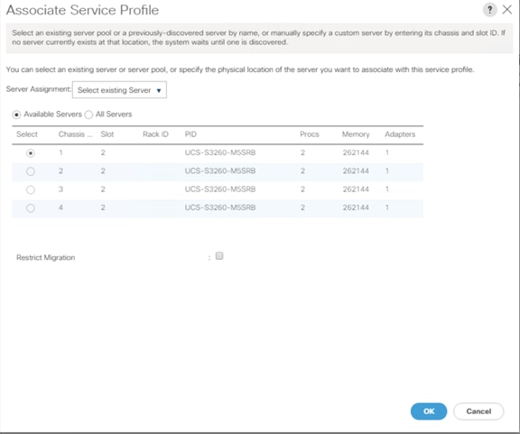
As previously described, when the service profile association is started, there are many activities that must take place to finalize the configuration of the server. The process can take some time to complete, especially if there are significant firmware updates to perform in order to comply with the policy. Before continuing with the Cohesity installation processes, wait for all of the servers to finish their association process and to show an overall status of OK, with no errors.
To view the servers’ discovery status, follow these steps:
1. In Cisco UCS Manager, click the Equipment button on the left-hand side, and click Equipment in the top of the navigation tree on the left.
2. In the properties pane, click the Chassis tab.
3. View the servers’ status in the Overall Status column and confirm the status as OK.
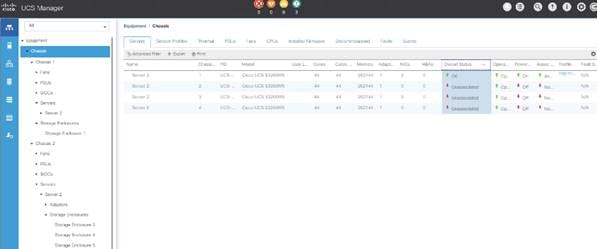
4. Confirm the Installed Firmware Version for each Chassis and Server node has a package version of 4.0(4i).
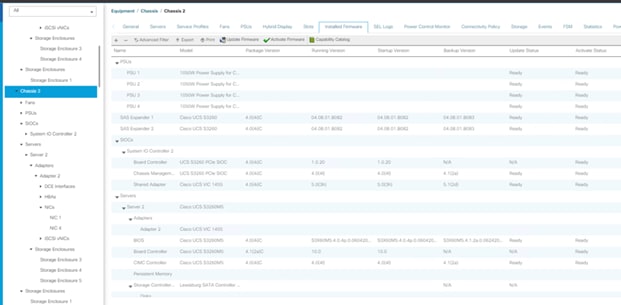
5. Repeat steps 1-4 to associate other server nodes provisioned for cohesity cluster deployment. Four Cisco UCS S3260 chassis with server node each are displayed in figure below.
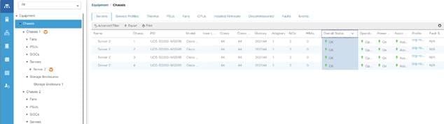
Cohesity Installation
Cohesity DataPlatform is installed in three phases; first is the initial software installation to all of the Cohesity nodes, followed by the initial network setup of a single node in order to access the Cohesity configuration webpage, and finally the initial Cohesity cluster configuration, which is done from the aforementioned webpage.
Cohesity Software Installation
The installation of Cohesity DataPlatform software is done through a bootable DVD ISO image file. Each node is booted from this image file, which will automate the process of installing the underlying Linux operating system, copy the Cohesity software packages, and prepare the nodes for the initial setup of the Cohesity cluster.
To install the Cohesity software on each Cisco UCS S3260 node, follow these steps:
1. In Cisco UCS Manager, click Servers.
2. In the tree hierarchy, underneath Service Profiles > root > Sub-Organizations, click the carat next to the name of the sub-organization created for Cohesity to expand it.
3. Each Cohesity node will have its own service profile, for example: Cohesity-sp-1. Right-click the first service profile and click KVM Console. The remote KVM console will open in a new browser tab. Accept any SSL errors or alerts, then click the link to launch the KVM console.
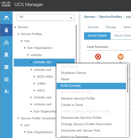
4. In the remote KVM tab, click the Virtual Media button in the top right-hand corner of the screen, then click Activate Virtual Devices.
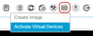
5. In the remote KVM tab, click the Virtual Media button in the top right-hand corner of the screen, then click the CD/DVD option.
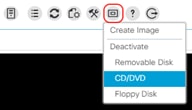
6. Click Choose File, browse for the Cohesity ISO installer file, and click Open.
7. Click CD/DVD.

8. In the remote KVM tab, click the Server Actions button in the top right-hand corner of the screen, the click Reset.
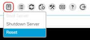
9. Click OK.
10. Choose the Power Cycle option, then click OK.
11. Click OK.
12. Observe the server going through the POST process until the Cohesity installer screen is displayed. We configured the Boot Policy with CD/DVD in first boot order, hence the Cohesity installer will load automatically
The server will boot from the remote KVM mapped Cohesity ISO installer and display the following screen:
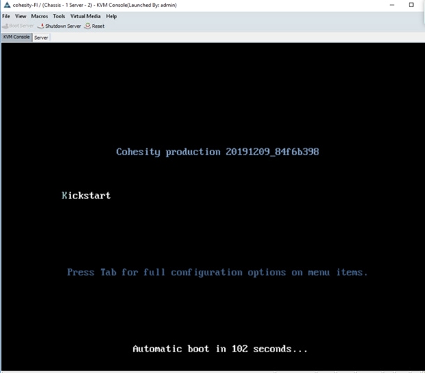
13. Allow the automatic timer to count down from 120 seconds, or press Enter.
The Cohesity installer will now automatically perform the installation to the boot media. Installation time takes approximately 30-35 minutes. Once the new server has completed the installation, the server will reboot, and it will be waiting at the console login prompt screen seen below. Pls note, the initial hostname would be the serial number of the server node in Cisco UCS S3260 chassis.
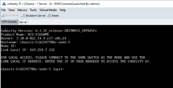
14. In the remote KVM tab, click the Exit button, then click Yes.
15. Repeat steps 3-14 for each additional Cohesity node being installed.
Cohesity First Node Configuration
In order to perform the initial cluster setup, the first node of the Cohesity cluster must be accessible through the network, so that the administrator performing the configuration can access the Cohesity configuration webpage running on that node. Cohesity nodes will automatically configure themselves with IPv6 link-local addresses and use these addresses to discover each other on the same subnet. These IPv6 addresses can also be used to perform the initial configuration through the webpage. However, many environments are not configured to use IPv6, therefore it is more common to use IPv4 addresses to perform the initial configuration. To use IPv4 addresses, the first node must be manually configured with an IPv4 address, so that the webpage is accessible to the administrator’s client computer.
To manually configure the first Cohesity node’s IPv4 addressing, follow these steps:
1. In Cisco UCS Manager, click Servers.
2. In the tree hierarchy, underneath Service Profiles > root > Sub-Organizations, click the carat next to the name of the sub-organization created for Cohesity to expand it.
3. Each Cohesity node will have its own service profile, for example: Cohesity-sp-1. Right-click the first service profile and click KVM Console. The remote KVM console will open in a new browser tab. Accept any SSL errors or alerts, then click the link to launch the KVM console.
4. When the node’s local login prompt appears, login with the following credentials:
a. Username: cohesity
b. Password: <password>
c. Go to the shell by entering ‘sh’ and password as <password>
d. Edit the network configuration through the network configuration script file
![]() Using sudo is required for root privileges.
Using sudo is required for root privileges.
sudo ~/bin/network/configure_network.sh
5. Select option 2 ‘Configure IP Address on interface’
6. Select default interface ‘bond0’
7. Enter IP Address, Interface Prefix and Gateway
8. Choose default MTU as 1500
9. Select ‘Y/Yes” to make the interface active
10. Quit the configure_network script by entering option ‘12’.
11. Test the network is working properly by pinging the default gateway. You can also verify the IP address configuration by issuing the following command:
ip addr
12. Log out of the node:
exit
13. In the remote KVM tab, click the Exit button, then click Yes.
![]() Note: On Linux operating systems, Cisco UCS Fabric Managed environment supports Bond Mode 1, 5 and 6. Reference : Bonding Options with the Cisco VIC Card . Cohesity deployed on Cisco UCS Fabric Managed environment supports only bond mode 1.
Note: On Linux operating systems, Cisco UCS Fabric Managed environment supports Bond Mode 1, 5 and 6. Reference : Bonding Options with the Cisco VIC Card . Cohesity deployed on Cisco UCS Fabric Managed environment supports only bond mode 1.
Cohesity Cluster Setup
The initial setup of the Cohesity cluster is done through the configuration webpage, which is now accessible on the first node, at the IP address which was configured in the previous steps. Prior to beginning the initial cluster configuration, ensure that all of the Cohesity nodes which are to be included in the cluster have completed their initial software installation, and are fully booted. Additionally, ensure that all of the necessary IP addresses for all of the interfaces are known and assigned, and the DNS round-robin entries have been created.
To perform the Cohesity initial cluster configuration, follow these steps:
1. In a web browser, navigate to the IP address of the first Cohesity node, which was just configured in the previous steps. For example: http://192.168.110.151
2. Accept any SSL warnings or errors due to the default self-signed certificate on the server and proceed to the Cohesity Dashboard login screen.
3. Log into the Cohesity Dashboard webpage using the credentials below:
a. Username: admin
b. Password: <password>

4. The Start Initial Cluster Setup screen appears, make sure that the number of nodes detected matches the number of servers you intend to install for this cluster. Click Get Started.
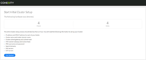
5. Select the nodes to add to this initial cluster or click the link to Select All Available in the upper right-hand corner, then click Select Nodes.
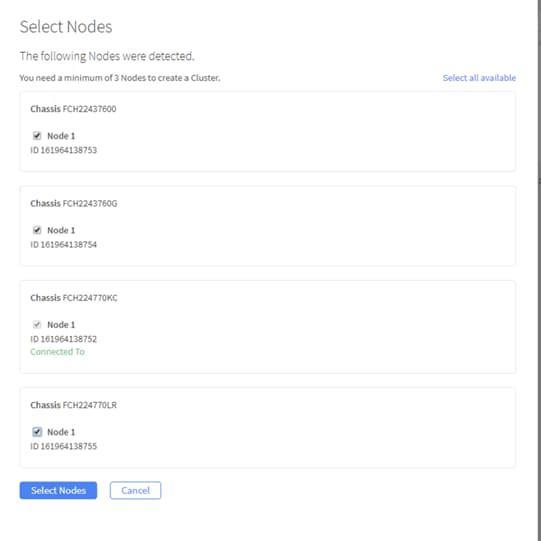
6. For each server, enter the IP address which will be assigned to the Linux node into the IP field.
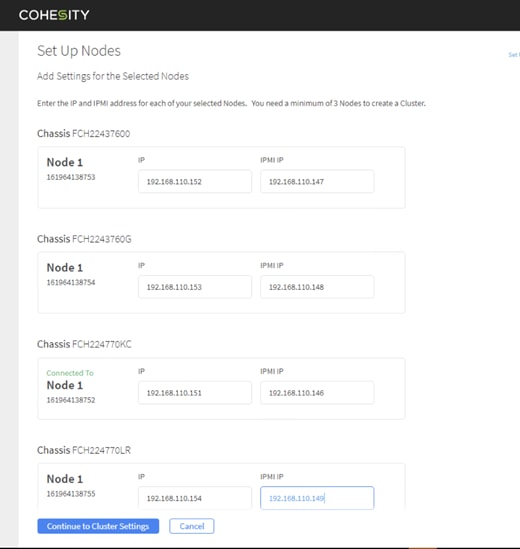
7. The Cohesity installation screen lists the serial numbers of the server node, which can be cross-referenced with the Equipment -> Chassis -> Chassis <1-4> -> Server2 view in Cisco UCS Manager. You need to traverse to all of the Chassis to identify Serial numbers of nodes in each chassis.
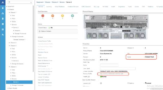
![]() The servers may not be listed in order, please refer to Cisco UCS Manager to ensure that you are entering the IP addresses in an order that corresponds to the server node serial number and service profiles. The Cohesity installation screen lists the serial numbers of the servers, which can be cross-referenced with the Management IP of the Service Profile in Cisco UCS Manager.
The servers may not be listed in order, please refer to Cisco UCS Manager to ensure that you are entering the IP addresses in an order that corresponds to the server node serial number and service profiles. The Cohesity installation screen lists the serial numbers of the servers, which can be cross-referenced with the Management IP of the Service Profile in Cisco UCS Manager.
8. Click the Service Profile name (as marked in screen above)and view Service Profile Properties
9. Identify the IPMI address (CIMC Management IP Address) in the IPMI IP field and enter the address in IPMI field in setup node screen of cohesity cluster creation and click Cancel.
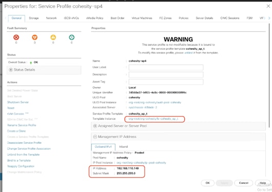
10. Enter the IPMI address to the identified server node serial number.
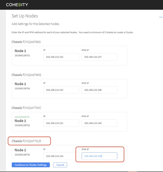
11. Repeat steps 7-10 and populate all the IPMI addresses corresponding to chassis server node serial numbers.
12. Click Continue to Cluster Settings.
13. Enter the desired name of the cluster and the DNS domain suffix.
14. Enter the gateway IP address and subnet mask for the IP addresses being assigned to the OS and VIPs of the nodes.
15. Enter the subnet mask and gateway address of the subnet where the nodes’ IPMI interfaces are configured.
![]() This is the subnet mask and gateway for the IP subnet used by the CIMC interfaces, also called the external management IP addresses.
This is the subnet mask and gateway for the IP subnet used by the CIMC interfaces, also called the external management IP addresses.
16. Enter the username and password for IPMI access, to match the username and password configured in the Cisco UCS Manager IPMI Access Profile, which was configured earlier.
17. Enter the required NTP server addresses, separated by commas.
18. Enter the hostname for the Cohesity cluster partition. This hostname typically matches the name of the cluster.
19. Enter the starting IP address for the VIP addresses that are being assigned to the Cohesity nodes. These IP addresses are the addresses which are resolved by DNS round-robin for the cluster, not the individual node IP addresses. For example: 192.168.110.155
20. Enter the last octet value for the end of the VIP range, for example: 234
21. Click Add VIP or VIP Range.
22. Optionally, choose to enable system wide encryption by toggling the switch. Encryption can be enabled at a later time for each separately configured storage domain. Because the latter option provides more flexibility, it is not recommended to enable system wide encryption at this time, as this choice cannot be reversed.
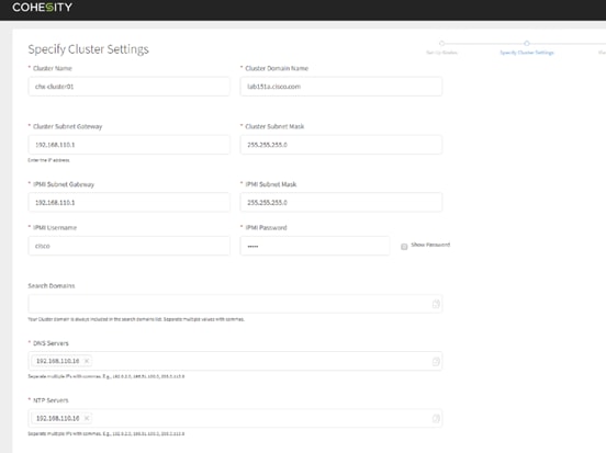
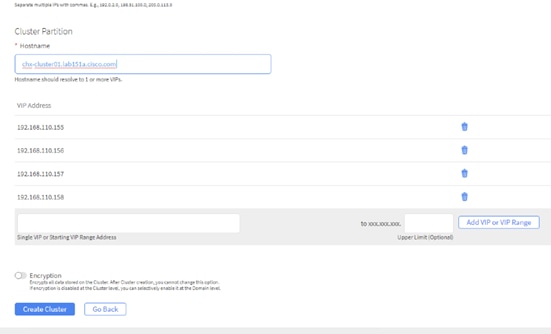
23. Click Create Cluster.
24. Observe the cluster creation status. Additional details can be viewed by clicking Show Details.
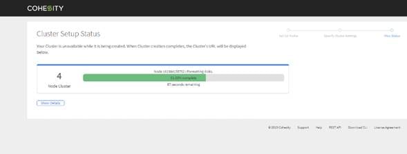
The status will appear to pause at 98-99% for a significant period of time while formatting the disks. The time to format nodes with 10 TB capacity disks will be longer than the time for nodes with 4 TB capacity disks. The time to create the cluster for a 4-node cluster with 10 TB disks is approximately 40 minutes.
After the setup completes, the web services will restart. After a few minutes, the Cohesity Dashboard webpage for the cluster will be available at the DNS round-robin address configured for the cluster. For example: https://chx-cluster01.lab151a.cisco.com.
Cohesity Cluster Expansion
This section described the cohesity cluster expansion procedure. With Cisco UCS stateless Service Profile, the hardware configuration of new Cisco UCS S3260 storage server can be achieved in few minutes. You can just instantiate another Service Profile from Service Profile template and associate it with the new server node configured for Cohesity cluster expansion.
To configure a new Chassis for cluster expansion and view the chassis discovery status, follow these steps:
1. In Cisco UCS Manager, click the Equipment button and click Equipment in the top of the navigation tree.
2. As the Server Port Auto-Discovery was set to auto, the chassis would be automatically discovered once the chassis MLOM ports are connected to the Fabric Interconnects. Ensure port 1 and port 2 of VIC 1455 are connected to Fabric Interconnect A , port 3 and port 4 are connected to Fabric Interconnect B
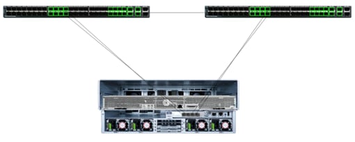
3. Click Chassis -> Chassis <n> and ensure that Chassis is discovered.
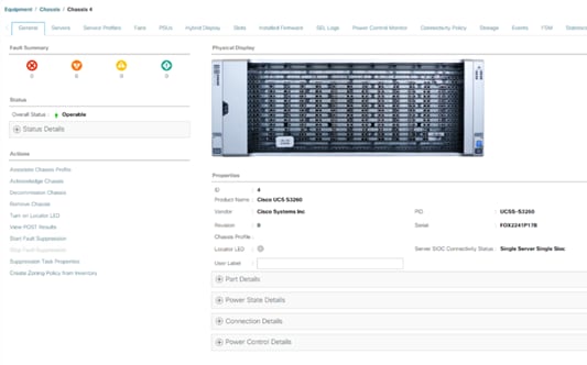
4. Under Chassis-> Chassis <n> -> Servers. Ensure Server node on S3260 Chassis is discovered as Server2 and is in unassociated state. In cohesity deployment on S3260, the server node resides on Server slot 2 of the Chassis. Ensure Server 2 on each Chassis is discovered and is in unassociated state.
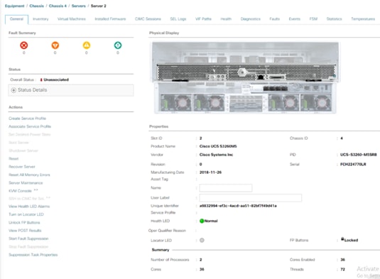
![]() The design also supports connecting just port 1 to FI A and port 3 to FI B.
The design also supports connecting just port 1 to FI A and port 3 to FI B.
5. Click the Chassis tab, in the tree hierarchy, underneath Chassis Profile Template > root > Sub-Organizations, click the carat next to the name of the sib-organization and Cohesity Chassis Profile Template.
6. Click Create Chassis Profile from Template.
7. Enter <cohesity_chs-p> as the Chassis profile prefix.
8. Enter 5 as “Name Suffix Starting Number and 1 as Number of Instances.
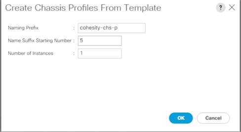
9. In the tree hierarchy, underneath Chassis Profiles > root > Sub-Organizations, click the carat next to the name of the sub-organization created for Cohesity to expand it.
10. Click the first Chassis Profile you wish to associate, then in the right-hand pane, click the blue link for “Change Chassis Profile Association”.
11. Select the discovered Chassis and click OK.
12. Monitor the Association of Chassis Profile in the FSM tab and ensure it succeeds.
13. When Chassis is Associated to Chassis Profile, we can associate a Service Profile to server node 2 of the chassis. As we instantiated Chassis Profile from a Chassis Profile Template we can create a Service Profile form the Service Profile Template created for Cohesity deployment.
14. Ensure there is IP available in the IP Pool created for KVM management of cohesity server nodes. The figure below elaborates on the availability of in IP server Pool.
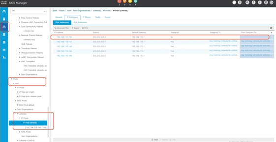
15. Click the Server tab in the right pane of UCS Manager, go to Service Profile Template created for cohesity <cohesity_sp_t>.
16. Right-click Template and create a Service Profile.
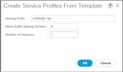
17. When Service Profile is instantiated, we can associate it to the Service node 2 of new chassis for Cohesity cluster expansion
18. Click Server tab, go to Servers > Service Profiles > root > <sub-organization> and click the service profile created in the previous step.
19. Click Change Service Profile Association, blue link and select existing server and check the server node under the S3260 Chassis.
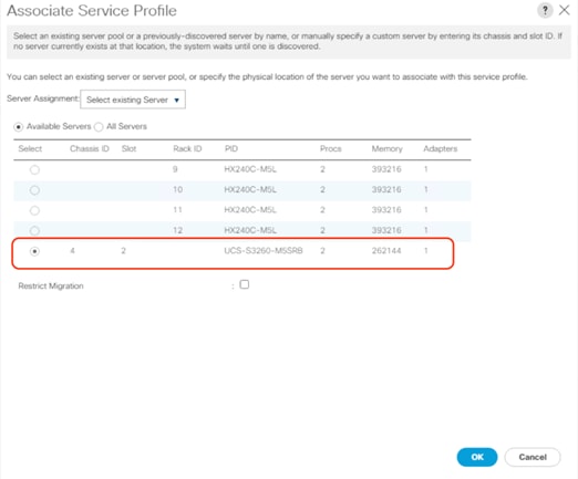
20. Click OK.
21. Monitor the server association status in the Server FSM tab.
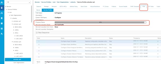
22. When the server Overall status is OK we can continue to installation of Cohesity software ISO through the UCS KVM console.
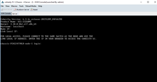
23. Add Virtual IP (VIP) in the DNS server for the new server node.
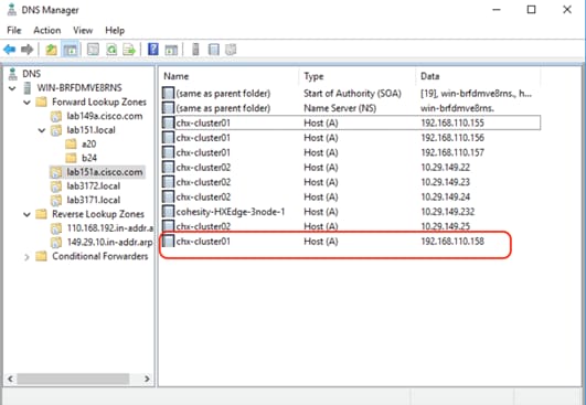
24. Go to Cohesity Dashboard > Select Platform > Cluster and select Nodes tab.
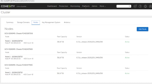
25. Click Add nodes. Cohesity Dashboard displays the new S3260 chassis node installed in the previous step.
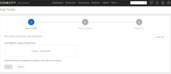
26. Select the node and click Next.
27. If there is a multiple node addition, the Cohesity installation screen lists the serial numbers of the server node, which can be cross-referenced with the Equipment -> Chassis -> Chassis <n> -> Server2 view in Cisco UCS Manager. For more than one node addition, we need to traverse to all of the Chassis to identify Serial numbers of nodes in each chassis.
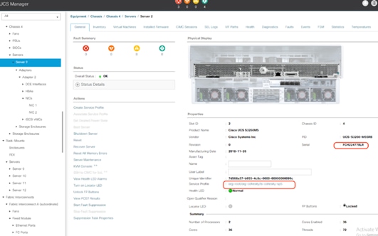
![]() For more than one node addition, the servers may not be listed in order, please refer to Cisco UCS Manager to ensure that you are entering the IP addresses in an order that corresponds to the server node serial number and service profiles. The Cohesity installation screen lists the serial numbers of the servers, which can be cross-referenced with the Management IP of the Service Profile in Cisco UCS Manager.
For more than one node addition, the servers may not be listed in order, please refer to Cisco UCS Manager to ensure that you are entering the IP addresses in an order that corresponds to the server node serial number and service profiles. The Cohesity installation screen lists the serial numbers of the servers, which can be cross-referenced with the Management IP of the Service Profile in Cisco UCS Manager.
28. Click the Service Profile name (as marked in screen above)and view Service Profile Properties.
29. Identify the IPMI address (CIMC Management IP Address) in the IPMI IP field and enter the address in IPMI field in setup node screen of cohesity cluster creation and click Cancel.
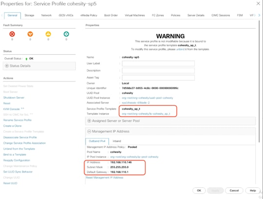
30. Enter the IPMI address and OS IP Address to the identified server node serial number, click Next.
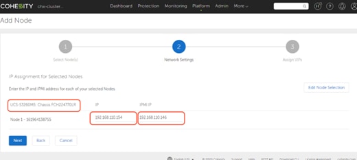
31. Add the Virtual IP for the new node. This is already configured in the DNS server to map with the cluster hostname.
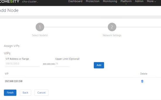
32. Click Finish. When the node addition workflow configured OS IP on the new node, go to Platform > Cluster > Nodes tab on Cohesity Dashboard and view the recently added node.
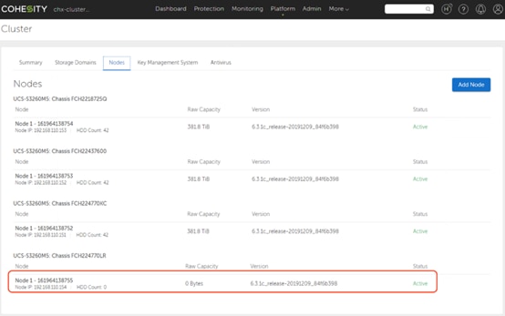
Cohesity Virtual Edition
Cohesity Virtual Edition (VE) offers a virtual machine-based installation of the Cohesity DataPlatform, which is deployed in smaller scale remote office and branch office (ROBO) locations. The Cisco HyperFlex Edge system offers a small scale, low cost deployment of the HyperFlex hyper-converged platform for ROBO locations, using the Cisco HX220c model servers, in a maximum cluster of 3 nodes. Cisco HyperFlex Edge operates without the use of Cisco UCS Fabric Interconnects, and instead utilizes standard 1 Gigabit or 10 Gigabit Ethernet switches. Cohesity VE is an ideal solution running within a Cisco HyperFlex Edge deployment, providing local protection of the virtual machines running in the Edge system, and also replicating the snapshots to a larger central Cohesity cluster. Cohesity policies control the retention periods for the local snapshot copies in the Edge system, and also the longer retention of the snapshots in the larger Cohesity clusters. This design allows for both local recovery of single or multiple virtual machines, while also providing disaster recovery of all the virtual machines in a ROBO site in case of a total loss or failure.
Cohesity Virtual Edition (VE) System Design
The Cohesity VE virtual machine is deployed from a downloaded OVA file into the Cisco HyperFlex Edge system. The OVA deployment requires a choice to be made between two virtual machine sizes; small and large. The configurations of the two sizes are outlined in the following table.
Table 29 Cohesity VE Virtual Machine Configurations
| Configuration |
vCPU |
RAM |
OS virtual disk |
Metadata virtual disk |
Data virtual disk |
| Small |
4 |
16 GB |
64 GB |
50 GB – 500 GB |
100 GB – 8000 GB |
| Large |
8 |
32 GB |
64 GB |
50 GB – 1000 GB |
100 GB – 16000 TB |
The primary factor in deciding which configuration of the Cohesity VE virtual machine to use is the sizing of the data virtual disk, which is the disk that will store the local snapshots of the protected virtual machines in the HyperFlex Edge system, until their local retention period has expired. The configurations of virtual CPU, RAM, OS disk and metadata disk sizes are fixed. The size of the data virtual disk must be larger than the metadata virtual disk and can be up to 16 times the size of the metadata virtual disk at maximum. Understanding the sizes of the virtual machines in the local system which will be protected, anticipated daily change rates, and the number of days to retain local copies will lead to an overall storage capacity necessary for the Cohesity VE virtual machine, and therefore naturally lead to which size to configure. For example, 8 virtual machines of 40 GB each will consume 320 GB of space for their initial snapshot, however the actual consumption will be less because the virtual machines contain unused space, and the Cohesity system will deduplicate and compress the snapshot data. If the actual storage space consumed for these 8 virtual machines initially is 80 GB, each day generates a further 8 GB of new snapshot data, and the desire was to keep 7 days of local copies, the total space required would be 136 GB, easily fitting within the small configuration.
The only additional configuration choice for the Cohesity VE virtual machine is whether to deploy the virtual machine with a single network interface, or with dual interfaces. In most situations, and for the purposes of this document a deployment with a single interface is sufficient. However, there may be circumstances where the management interfaces of the Cohesity VE virtual machine, the HyperFlex ESXi hosts, and the vCenter server managing the HyperFlex Edge system may be configured on separate VLANs from the network pathway across the LAN/WAN that can access the remote Cohesity cluster for replication. In this scenario, one network interface for the Cohesity VE virtual machine must be configured with an IP address which is valid on the management VLAN, and therefore capable of performing the protection jobs, while the second interface has an IP address configured on the VLAN that can reach the remote Cohesity cluster across the LAN/WAN for replication.
Cohesity VE Prerequisites
Prior to beginning the deployment of a Cohesity VE virtual machine, several pieces of information must be assembled for the configuration of the system. The Cohesity VE hostname must be added to the resolving DNS server(s) as an A record, which resolves to the IP address of the virtual machine. The following tables will assist with gathering the required network information and prerequisites for the installation, by listing the information required, and an example configuration:
Table 30 Cohesity VE Network Information
| Item |
Value |
| IP Address Interface #1 |
|
| Subnet Mask Interface #1 |
|
| Gateway Interface #1 |
|
| IP Address Interface #2 (if applicable) |
|
| Subnet Mask Interface #2 (if applicable) |
|
| Gateway Interface #2 (if applicable) |
|
| DNS Server #1 |
|
| DNS Server #2 |
|
| DNS Domain |
|
| NTP Server #1 |
|
| NTP Server #2 |
|
| Cohesity VE Cluster Name |
|
| vCenter Server Name |
|
| HyperFlex Edge Cluster Management IP Address |
|
Table 31 Cohesity VE Example Network Information
| Item |
Value |
| Cohesity DataNetwork |
Storage Controller Management Network |
| IP Address Interface #1 |
xxx.xxxx.xxxx.xxx |
| Subnet Mask Interface #1 |
xxx.xxxx.xxxx.xxx |
| Gateway Interface #1 |
xxx.xxxx.xxxx.xxx |
| IP Address Interface #2 (if applicable) |
|
| Subnet Mask Interface #2 (if applicable) |
|
| Gateway Interface #2 (if applicable) |
|
| DNS Server #1 |
xxx.xxxx.xxxx.xxx |
| DNS Server #2 |
xxx.xxxx.xxxx.xxx |
| DNS Domain |
xxx.xxxx.xxxx.xxx |
| NTP Server #1 |
xxx.xxxx.xxxx.xxx |
| NTP Server #2 |
xxx.xxxx.xxxx.xxx |
| Cohesity VE Cluster Name |
hxedge-2node1.b24.lab151.local |
| vCenter Server Name |
vcenter-2node.b24.lab151.local |
| HyperFlex Edge Cluster Management IP Address |
xxx.xxxx.xxxx.xxx |
Cohesity VE Installation
Cohesity VE is deployed as a virtual machine into the Cisco HyperFlex Edge cluster, installed via a downloadable OVA file from Cohesity. To deploy the Cohesity VE virtual machine, follow these steps:
1. Open the vSphere Web Client webpage, or the vSphere HTML5 Web Client webpage of the vCenter server managing the HyperFlex cluster where the installer OVA will be deployed and log in with admin privileges.
2. In the vSphere Web Client, from the Home view, click Hosts and Clusters.
3. Click in the name of the Cisco HyperFlex cluster where the virtual machine will be deployed.
4. Either right-click the cluster, or from the Actions menu, click Deploy OVF Template.
5. Click the Local file option, then click Browse and locate the Cohesity VE OVA file, for example cohesity-6.1.1d_release-20190228_176cd13b.ova, click the file and click Open.
6. Click Next.
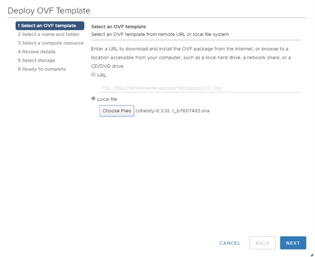
7. Modify the name of the virtual machine to be created if desired and click a folder location to place the virtual machine, then click Next.
8. Click a specific host or cluster to locate the virtual machine and click Next.
9. After the file validation, review the details and click Next.
10. Select either the Small or Large configuration radio button and click Next.
11. Select a Thick Provision Lazy Zeroed virtual disk format, and the Cisco HyperFlex datastore to store the new virtual machine, then click Next.
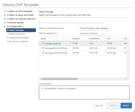
12. Modify the network port group selection from the drop-down list in the Destination Networks column, choosing the network the installer virtual machine will communicate on for the primary interface named “DataNetwork”, plus the optional second interface named “SecondaryNetwork”. For HyperFlex Edge, the DataNetwork should be ‘Storage Controller Management Network’.
13. Under the IP Allocation Settings section, leave the dropdown selection for IP Allocation set to “Static – Manual” if static addresses will be used, or modify the setting to DHCP, and click Next.
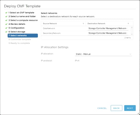
14. If DHCP is to be used for the installer virtual machine, leave the fields blank and click Next. If static addresses are to be used, fill in the fields for the IP address, gateway, and subnet mask for the primary interface, and optionally the secondary interface, then click Next.
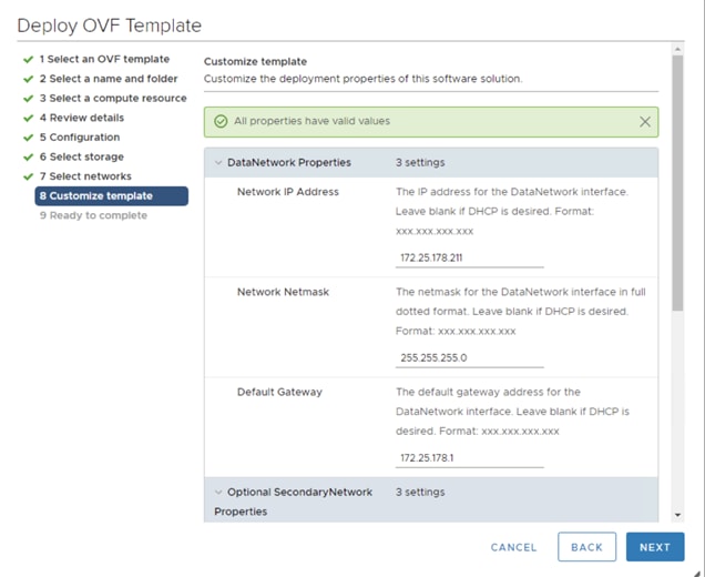
15. Review the final configuration and click Finish.
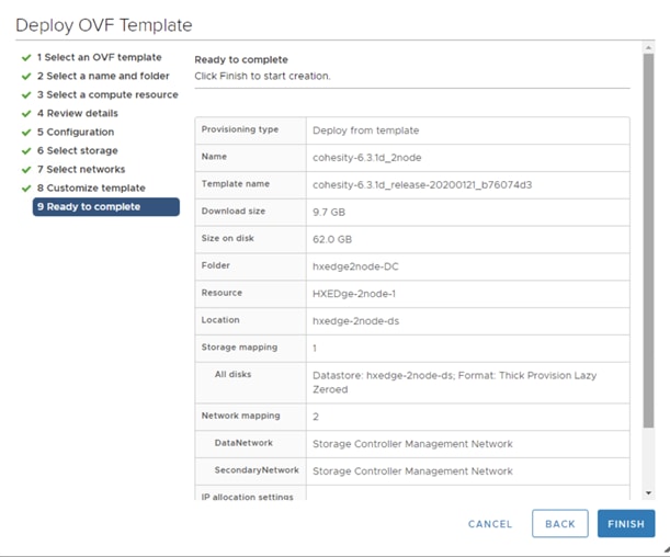
![]() The installer virtual machine will take a few minutes to deploy, do not power on the virtual machine at this time.
The installer virtual machine will take a few minutes to deploy, do not power on the virtual machine at this time.
Before powering on the virtual machine, follow these steps to add the additional virtual disks to the virtual machine.
1. After the OVA completes deployment, right-click the virtual machine and click Edit Settings.
2. In the upper right-hand corner, click Add New Device, and click Hard Disk. This will be the metadata virtual disk.
3. Click on the carat (>) next to the “New Hard Disk” which was added in order to expand the settings of the new device.
4. Modify the size of the disk to either 50 GB-500 GB for the small Cohesity VE configuration, or 50 GB – 1000 GB for the large configuration.
5. Ensure the Disk Provisioning setting is set to Thick Provision Lazy Zeroed.
6. Change the Disk Mode setting to Independent – Persistent.
7. Modify the Virtual Device Node setting to SCSI Controller 1 – SCSI(1:0)
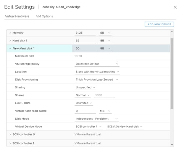
8. In the upper right-hand corner, click Add New Device, and click Hard Disk. This will be the data virtual disk.
9. Click the carat (>) next to the “New Hard Disk” which was added in order to expand the settings of the new device.
10. Modify the size of the disk to either a minimum of 100 GB for the small and large Cohesity VE configuration, The maximum size of the data virtual disk is 8000 GB for the small configuration, or 16000 GB for the large configuration.
![]() At most, allocate 16 times more disk space to the Data Tier drive than the Metadata drive. The Metadata drive size must be smaller than the Data Tier drive size.
At most, allocate 16 times more disk space to the Data Tier drive than the Metadata drive. The Metadata drive size must be smaller than the Data Tier drive size.
11. Ensure the Disk Provisioning setting is set to Thick Provision Lazy Zeroed.
12. Change the Disk Mode setting to Independent – Persistent.
13. Modify the Virtual Device Node setting to SCSI Controller 2 – SCSI(2:0)
14. Click OK.
15. Power on the new Cohesity VE virtual machine.
Cohesity VE Initial Setup
The initial setup of the Cohesity VE virtual machine is done via the configuration webpage, which is now accessible at the IP address which was configured in the previous steps. Prior to beginning the initial cluster configuration, ensure that the necessary IP address(es) for the interface(s) are known and assigned, and all required DNS A records have been created.
To perform the Cohesity VE initial configuration, follow these steps:
1. In a web browser, navigate to the IP address of the first Cohesity node, which was just configured in the previous steps. For example: http://172.25.178.211
2. Accept any SSL warnings or errors due to the default self-signed certificate on the server and proceed to the Cohesity Dashboard login screen.
3. Log into the Cohesity Dashboard webpage using the credentials below:
a. Username: admin
b. Password: <password>
4. The Virtual Edition Cluster Setup screen appears, click Get Started.
5. Enter the Cluster Name, Cluster Domain Name, the Cluster Subnet Gateway and Subnet Mask, and the Node IP Address.
6. Enter the DNS search domains, the DNS server IP address(es), and NTP server IP addresses.
7. Enter the full DNS hostname of the Cohesity VE system, and optionally turn on Data Encryption.
8. Click Create Cluster.
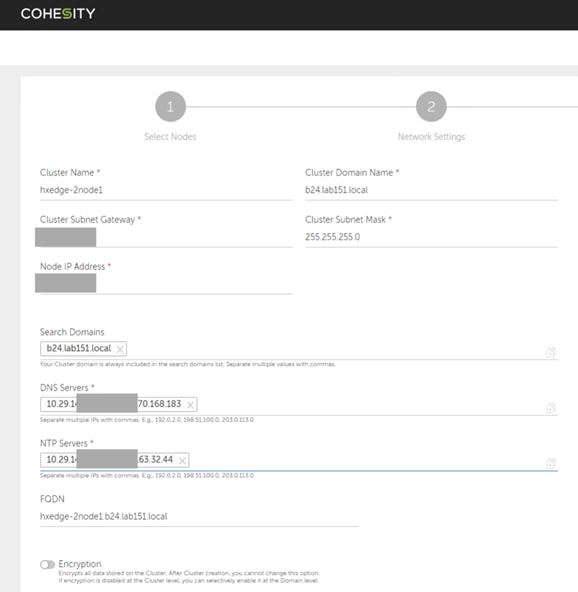
After the cluster creation completes, the Cohesity VE system is ready for use. To ensure the continued operation of the Cohesity VE system in case of a failure of one of the Cisco HyperFlex nodes, ensure that the vSphere High Availability setting is enabled for the ESXi cluster where the Cohesity VE virtual machine operates. This feature is normally enabled by default as part of the Cisco HyperFlex installation. To complete a typical Cohesity VE installation, refer to the following sections of this document to configure:
· Modify the default passwords and optionally enable external authentication
· Modify or create additional storage domains to enable/disable compression, deduplication, and encryption of the stored snapshots
· Add remote clusters to enable the ability to replicate snapshots between Cohesity systems
· Register vCenter and Cisco HyperFlex sources
· Create or modify policies to control protection job retention and replication
· Create protection jobs to back up the virtual machines running alongside the Cohesity VE virtual machine within the Cisco HyperFlex Edge system
Cohesity Dashboard
The primary management interface for the Cohesity DataPlatform is the embedded Cohesity Dashboard web interface. All cluster configurations, policies, jobs, and activities can be created, modified, and monitored via the Cohesity Dashboard.
To log into the Cohesity Dashboard, follow these steps:
1. In a web browser, navigate to the DNS round-robin name of the Cohesity cluster, which was set up in the previous steps. For example: https://chx-cluster01.lab151a.cisco.com
2. Accept any SSL warnings or errors due to the default self-signed certificate on the server and proceed to the Cohesity Dashboard login screen.
3. Log into the Cohesity Dashboard webpage using the credentials below:
a. Username: admin
b. Password: <password>
4. Accept the End User Licensing agreement by clicking Accept.
5. Enter a valid Cohesity license code.
6. Click Submit.
Cluster Configuration
After the initial Cohesity cluster setup has completed, the system is operating with a preset collection of default settings. In order to tailor the cluster to your individual needs, these various settings should be modified.
Partitions
Conceptually, a Cohesity cluster is a collection of nodes running the Cohesity software, which provide storage resources. A Cohesity cluster contains a single partition, therefore the partition is synonymous to the overall cluster. There are some settings which are modified as an overall cluster, and some advanced settings that can be configured at the partition level, such as custom host mappings, or VLANs. These settings are not required to be modified in the example configuration detailed in this document, and in most circumstances, the default partition, named “DefaultPartition” can be left unmodified.
Storage Domains
Storage Domains represent a subdivision of the default partition, and many settings can be modified at the Storage Domain level. In particular, settings for deduplication, compression, encryption, and data replication can all be controlled individually for each Storage Domain that is created. Protection Jobs and Views all target a specific Storage Domain in their configurations. This arrangement provides additional flexibility, because through the use of multiple domains, which are then targeted by different jobs and workloads, each of them can be tailored to meet the requirements of that job or workload. Because a Cohesity VE system is operating as a single node, only a single copy of the data is held locally and the settings for data replication within a Storage Domain are not available, therefore only deduplication, compression and encryption settings can be modified.
To modify the default Storage Domain of the Cohesity cluster, follow these steps:
1. Log into the Cohesity Dashboard web page.
2. From the Platform menu at the top of the screen, click Cluster.
3. Click the Storage Domains tab.
4. Click the ellipses to the far right-hand side of the line item of the “DefaultStorageDomain”, then click Edit.
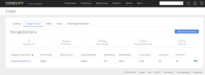
5. Modify the name of the domain to one which helps to identify the usage and/or settings of this domain, for example, “domain_rf2_1” which indicates a domain using a data replication factor of 2 for redundancy, plus inline deduplication, and inline compression.
6. Modify the settings of this domain for deduplication, compression, encryption, quotas, and failure tolerance as required.
7. Click Update Storage Domain.
To create additional Storage Domains with unique settings from the default domain, follow these steps:
1. Log into the Cohesity Dashboard web page.
2. From the Platform menu at the top of the screen, click Cluster.
3. Click the Storage Domains tab.
4. Click Add Storage Domain.
5. Enter the name of the domain, choosing one which helps to identify the usage and/or settings of this domain, for example, “domain_ec2_id_ic” which indicates a domain using erasure coding with 2 stripes for redundancy, plus inline deduplication, and inline compression.
6. Modify the settings of this domain for deduplication, compression, encryption, quotas, and failure tolerance as required.
7. Click Create Storage Domain.
Time zone
By default, a newly installed Cohesity cluster operates in the UMT (GMT+0) time zone. Organizations have many different standards for which time zone their hardware is configured to operate in. Some choose to have all hardware remain in UMT, others have all hardware operate in a single time zone regardless of physical location, meanwhile many always choose the local time zone of the hardware’s physical location. Reliable NTP servers are required and defined during the cluster installation. Ensure that the NTP servers listed are accessible from the network where the Cohesity cluster is installed.
To modify the time zone of the Cohesity cluster, follow these steps:
1. Log into the Cohesity Dashboard web page.
2. From the Admin menu at the top of the screen, click Cluster Settings.
3. Click the link labeled “Change Time zone”.
4. From the drop-down list, select the appropriate time zone for this cluster.
5. Click Save.
Security
A newly installed Cohesity cluster has a single administrative user named “admin” with a default password. No additional external authentication sources are configured during the installation. At a minimum, the default admin user’s password should be modified away from the default.
Active Directory
Integration with Microsoft Active Directory allows for Active Directory user accounts to log into the Cohesity cluster to administer and use the system, plus it enables additional options to be selected and modified when creating Views that use the SMB protocol.
To join the Cohesity cluster to an Active Directory domain, follow these steps:
1. Log into the Cohesity Dashboard web page.
2. From the Admin menu at the top of the screen, click Access Management.
3. Click the Active Directory tab.
4. Click the link for Join Domain.
5. Enter the Active Directory domain name.
6. Enter a username and password for a user with administrative rights to join computers to the Active Directory domain.
7. Optionally, enter a specific Organizational Unit where the computer account should be located in the Active Directory hierarchy.
![]() The Cohesity cluster name will automatically be listed as the machine account to be created. As long as the DNS round-robin records have been properly created prior to the Cohesity cluster installation, this is the only machine account name that is necessary.
The Cohesity cluster name will automatically be listed as the machine account to be created. As long as the DNS round-robin records have been properly created prior to the Cohesity cluster installation, this is the only machine account name that is necessary.
8. Click Add Active Directory.
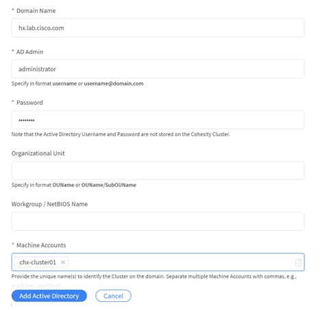
Users and Roles
Additional local or Active Directory users can be created to allow them to log into the Cohesity system and perform tasks according to the roles assigned to their account, which are defined in the cluster.
To add an authorized user to the Cohesity cluster, follow these steps:
1. Log into the Cohesity Dashboard web page.
2. From the Admin menu at the top of the screen, click Access Management.
3. Click Add Users/Groups.
4. Select the radio button for either a Local User or an Active Directory User & Groups.
5. For a local user, enter the username, email address, password, and select a Role from the drop-down list.
6. For an Active Directory User or Group, select the Active Directory Domain from the drop-down list, search for and select either the AD user or group you wish to add, then select a Role from the drop-down list.
7. Click Add.
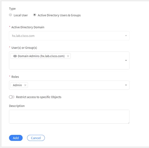
Passwords
Prior to changing the default System Admin account password, it is highly recommended to create at least one additional local, Active Directory, or LDAP user account with the Admin Role as outlined above. Using this secondary administrative account to make the password change ensures that administrators do not accidentally get locked out of the cluster due to a faulty password change.
To change the default System Admin password, follow these steps:
1. Log into the Cohesity Dashboard web page as a user with the Admin Role.
2. From the Admin menu at the top of the screen, click Cluster Settings.
3. Toggle the radio switch for “Change System Admin Password”.
4. Enter and confirm the new password for the local admin account.
5. Click Save.
Sources
Cohesity can provide protection for multiple platforms, including virtual machines running across a variety of hypervisors, cloud-based virtual machines, bare-metal servers, Oracle and Microsoft SQL databases, plus direct protection of storage array volumes. Cohesity protection jobs are each configured to target specific sources, therefore prior to configuring the protection jobs the sources must be registered with the Cohesity cluster.
Hypervisor Source
Protection of a VMware ESXi based cluster is conducted via the managing VMware vCenter Server. Cisco HyperFlex clusters running on VMware ESXi hypervisors also use vCenter for management of the cluster. To configure protection of a Cisco HyperFlex ESXi based cluster, the managing vCenter server must be registered as a source for the protection jobs.
To configure a hypervisor source, follow these steps:
1. Log into the Cohesity Dashboard web page.
2. From the Protection menu at the top of the screen, click Sources.
3. Click Register and from the drop-down list that appears, click Hypervisor.
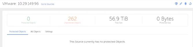
4. From the Hypervisor Source Type drop-down list, choose VMware: vCenter
5. Enter the hostname or IP address of the vCenter server managing the Cisco HyperFlex cluster being protected, and an administrative username and password.
6. Toggle the radio button on for the “Auto Cancel Backups if Datastore is running low on space” option and enter a minimum value of free space for the datastore. If the datastore housing the virtual machines being snapped drops below this amount of free space, the job will be automatically cancelled.
7. Click Register.
Storage Snapshot Provider
The Cohesity DataPlatform offers integration with storage-based snapshots, leveraging the native snapshot technologies built directly into the storage arrays, versus using the standard VMware based virtual machine snapshots. Cisco HyperFlex offers native storage-based snapshots, which provide space-efficient and crash-consistent snapshots taken by the underlying Cisco HyperFlex Distributed Filesystem, instead of standard VMware redo-log based snapshots. By using this integration via the Cisco HyperFlex API, the Cohesity protection jobs will take Cisco HyperFlex native snapshots instead of VMware snapshots. Cohesity protection jobs will always fall back to taking VMware native snapshots in case the HyperFlex native snapshot was not available. In order to use the Cisco HyperFlex API to create native snapshots, the Cisco HyperFlex cluster(s) must be registered as a Storage Snapshot Provider source.
In order for Cohesity Protection Jobs to always use native HX snapshots of the virtual machines running in the Cisco HyperFlex cluster(s), it is important that the virtual machines to be protected not have any existing standard VMware redo-log based snapshots. An existing VMware snapshot will prevent the creation of a subsequent HX native snapshot, and instead all snapshots taken by the Cohesity system will continue to be VMware snapshots. In this situation, prior to configuring Cohesity Protection Jobs it is recommended to delete all existing VMware snapshots from the virtual machines running in the Cisco HyperFlex cluster(s), which will be protected by Cohesity using the Storage Snapshot Provider integration. For virtual machines which already have existing HX native snapshots, no action is necessary, because subsequent snapshots taken by the Cohesity system using the Storage Snapshot Provider integration will continue to be HX native snapshots.
To configure Cisco HyperFlex as a Storage Snapshot Provider source, follow these steps:
1. Log into the Cohesity Dashboard web page.
2. From the Protection menu at the top of the screen, click Sources.
3. Click Register and from the drop-down list that appears, click Storage Snapshot Provider.
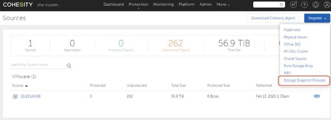
4. From the Snapshot Storage Provider Type drop-down list, choose Storage Snapshot Provider: HyperFlex
5. Enter the hostname or IP address of the roaming management interface of the Cisco HyperFlex cluster being protected, and an administrative username and password. This must be the roaming or floating management IP address, not the management IP address of any individual Cisco HyperFlex node.
6. Click Register.
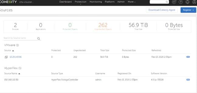
Remote Clusters
When multiple Cohesity systems are available across the landscape, such as multiple Cohesity VE virtual machines and other larger Cohesity clusters, the Cohesity systems can be registered with one another for both remote management and replication of backed up snapshots across the network. When remote access is enabled, the name of the Cohesity cluster or system in the upper left-hand corner of the Cohesity Dashboard screen becomes a selectable drop-down list. From this menu you can choose which connected remote or local Cohesity system to manage, without having to log in to each system separately.
When replication between remote Cohesity systems or clusters is enabled, Cohesity policies allow for a secondary copy of the Protection Job snapshots to be replicated to a different Cohesity cluster, which can be located in a standby datacenter used for disaster recovery. This secondary Cohesity cluster can have a standby VMware vCenter server registered as a source, and backups can quickly be restored to this recovery system in case a disaster is declared, or a planned failover to the secondary system is required. In order to replicate snapshots, the originating cluster (i.e. the cluster which captures the snapshot) must register the receiving cluster, and in return, the receiving cluster must register the originating cluster. A pairing is established between Storage Domains in the two clusters. A single Storage Domain in the originating cluster is paired with a single Storage Domain in the receiving cluster. A many-to-one pairing can be done only across multiple originating clusters, each one pairing a single Storage Domain, but all of them paired with the same receiving Storage Domain. Replication frequency and retention is controlled as part of the Cohesity policies, which each Protection Job is then assigned to follow. Protection jobs which have been configured to replicate to a remote cluster will also appear as inactive jobs on the receiving Cohesity system. These inactive jobs can be failed over to the receiving system in case of a disaster, and a recovery job can then be initiated.
To register remote clusters, follow these steps:
1. Log into the Cohesity Dashboard web page.
2. From the Protection menu at the top of the screen, click Remote Clusters.
3. Click the Add Cluster button.
4. Enter one or more of the Virtual IP addresses of the remote cluster nodes.
5. Enter the username and password of a user with administrative rights in the remote cluster, then click Connect.
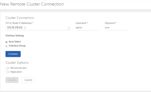
6. Toggle the switches to enable Replication, and Remote Access if desired.
7. Click the link to Add Storage Domain Pairing and choose the local and remote Storage Domains to pair, then click Add.
8. Optionally, select to enable load distribution, outbound compression, data encryption, transfer speed limits and overrides as needed.
9. Click Create.
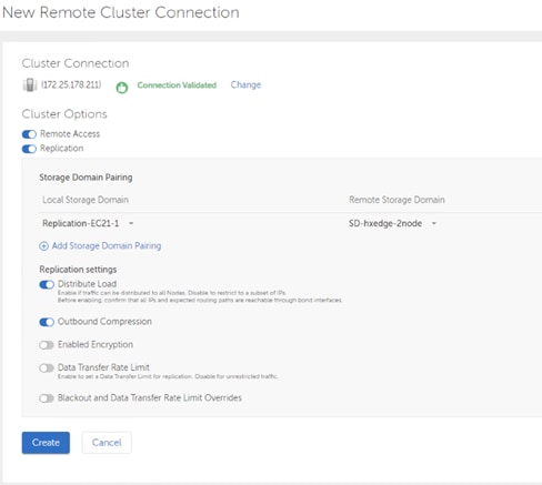
10. Repeat steps 1 through 9 on the second Cohesity cluster, registering the cluster in the opposite direction of the first registration.

External Targets
In addition to replication of snapshots between multiple Cohesity clusters, Cohesity can be configured to copy snapshots to non-Cohesity locations, which is referred to as Archiving. Archival is controlled via the Cohesity policies in the same manner as Replication, and as with Replication, the External Target must be configured as a possible location for the archival task. Multiple types of External Targets are available, including Google, Amazon Web Services, Microsoft Azure, Network Attached Storage (NAS), and more. As such, this document will not describe all of the options available for configuration of these External Targets.
Policies
Cohesity policies define the backup types, frequency, retention periods, replication, and archival options for protection jobs. Three standardized policies are included by default during the installation, however in many cases these options will need to be customized for your specific use. The default policies can be edited; however, it is recommended to make a copy of one of the default policies to use as a starting point. Alternatively, a new policy can be created from scratch.
To configure Cohesity policies, follow these steps:
1. Log into the Cohesity Dashboard web page.
2. From the Protection menu at the top of the screen, click Policy Manager.
3. Click Create Policy.
4. Alternatively, click the ellipses next to an existing policy and click Edit Policy.
5. In addition, you may click the ellipses next to an existing policy and click Copy Policy. The subsequent policy may then be edited.
6. Enter a name for the Policy being created or edited, and optionally enter a description.
7. Toggle the DataLock radio button option if desired. DataLock will prevent snapshots from being removed from the cluster, even if the protection job is deleted, until the snapshot has exceeded its retention period. This allows for additional policy compliance and data protection against unintended deletion of snapshots.
8. Configure the backup schedule to define the frequency of the job, along with the retention period for the snapshots to be kept.
9. The default option is for every backup job since the first to be run as an incremental job, saving space and network bandwidth. The option can be modified to perform a full backup at regular intervals if desired.
10. Extended retention can be configured to keep specific regular snapshots for longer retention periods than the standard retention schedule, if desired.
11. Blackout periods can be configured, to prevent new runs of a job configured with this policy from starting if the current time is within the blackout period.
12. Optional: If there are multiple Cohesity clusters available, the clusters can be registered with each other and then configured to replicate the snapshots being backed up. Configure replication of the backups to the remote Cohesity cluster if applicable. For instance, to protect application VMs on HX Edge cluster we configure a replication target as the cohesity cluster deployed on Main Data Center with either Cisco UCS S3260 Storage servers or Cisco UCS C240 M5 Rack Servers.
13. Keep the ‘Replicate only fully successful runs’ to the default as unchecked. Check this box if you want replication to occur only if the job run successfully backs up all the protected objects, such as 10 out of 10 VMs
14. Optional: If External Targets are available, such as cloud providers, storage arrays and object-based S3 storage systems, these external targets can act as archival locations for off-site storage of Cohesity backups. Configure archival of the backups to the remote target if applicable.
15. Click Create or Save as applicable.
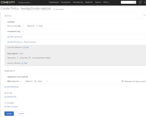
Protection
Protection Jobs are configured in the Cohesity Dashboard to back up the configured sources, according to the Policies defined in the system. Each protection job obtains data from a single Source, operates according to the settings in a single Policy, and targets a single Storage Domain to store the snapshots. Because of this operational method, in order to back up virtual machines according to different schedules, or to target a different Storage Domain, a unique Protection Job must be created for each case. In the same way, backing up virtual machines from different sources, such as multiple Cisco HyperFlex clusters, or combinations of other sources, must be done in a distinct Protection Job per unique source.
During a Cohesity Protection Job, a new snapshot of the virtual machine is taken, and that snapshot is transferred via the network to the Storage Domain configured in the job. This constitutes a new incremental backup of that virtual machine. Once the snapshot is transferred, the snapshot of the virtual machine is deleted in the source hypervisor node. If the virtual machine being backed up was already running with an active snapshot, the new snapshot taken by Cohesity will be a child of the existing snap, then it will be deleted, coalescing the changes back into the existing snapshot level where the virtual machine was already running. If the Storage Snapshot Provider integration with Cisco HyperFlex is enabled, then all of these snapshots will be taken as HX native snapshots. If the HX native snapshot attempt should fail, for example when an existing VMware standard redo-log snapshot exists, then the Protection Job will fall back to taking a standard VMware snapshot.
Of special note is a circumstance where a virtual machine has multiple snapshots, but the virtual machine has been reverted to a previous snapshot and is therefore not running as the most recent snapshot. Cohesity Protection Jobs will take the snapshot at the level where the virtual machine is currently running, therefore, any changes contained in a child snapshot that is not the current running snapshot of the virtual machine, will not be captured in the Cohesity backup. The existence of unused child snapshots will cause warnings during the execution of a Cohesity Protection Job, and such unused snapshots should be removed.
![]() WARNING! When configuring Protection Jobs of Cisco HyperFlex clusters, it is critical that the HyperFlex Storage Controller Virtual Machines (SCVMs, which start with virtual machine name stCtlVM-*) are not configured to be protected. Taking snapshots of the SCVMs and attempting to restore them is not a supported operation in Cisco HyperFlex clusters.
WARNING! When configuring Protection Jobs of Cisco HyperFlex clusters, it is critical that the HyperFlex Storage Controller Virtual Machines (SCVMs, which start with virtual machine name stCtlVM-*) are not configured to be protected. Taking snapshots of the SCVMs and attempting to restore them is not a supported operation in Cisco HyperFlex clusters.
To create a Protection Job, follow these steps:
1. Log into the Cohesity Dashboard web page.
2. From the Protection menu at the top of the screen, click Protection Jobs.
3. Click the Protect button, from the drop-down list that appears, click Virtual Server.
4. Enter a name for the job, and optionally enter a description.
5. Select a source for the job from the drop-down list.
6. From the pop-up window that appears, choose the virtual machine(s) that you wish to protect in this job.
7. The three buttons on the top right of the window can be used to switch between a hierarchical inventory view, a folder view, or a list view of the virtual machines.
8. The list of virtual machines may be searched for a specific virtual machine name or names using the wildcard character (*) by clicking in the field next to magnifying glass button.
9. The list of virtual machines can also be filtered using the drop-down list, for example choosing to show only virtual machines which are currently unprotected.
10. Individual virtual machines can be chosen by clicking the checkbox next to their name or it is possible to protect entire clusters, hosts, or folders by clicking the checkbox next to them.
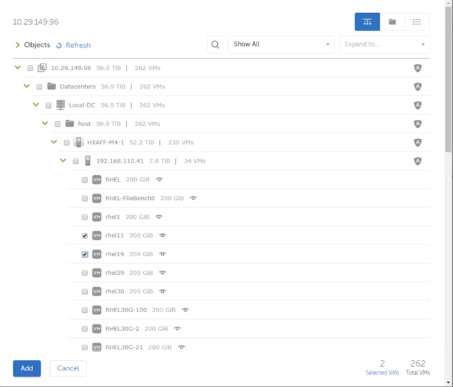
11. Click Add.
12. Select a policy from the drop-down list.
13. Select a storage domain from the drop-down list.
14. In order to take advantage of the Storage Snapshot integration with Cisco HyperFlex clusters, in the Advanced section, click the Edit link next to “Leverage Storage Snapshots for Data Protection.” Toggle the radio button on and select HyperFlex from the drop-down list that appears.
15. Enable App Consistent Backups if necessary, for example if the virtual machine is running transactional software or databases which require the virtual machine’s filesystem to be quiesced as part of the backup. In the Advanced section, click the Edit link next to “App Consistent Backups”. Toggle the radio button on, and optionally choose to fall back to a standard crash consistent snapshot, without quiescing the filesystem, should the quiesce operation fail.
![]() WARNING! Guest virtual machines must be running the most current version of VMTools in order for quiesced snapshots to be taken properly, and application consistent backups to be performed.
WARNING! Guest virtual machines must be running the most current version of VMTools in order for quiesced snapshots to be taken properly, and application consistent backups to be performed.
16. Optionally, modify the remaining job parameters as required. For example, modify the End Date to stop the job from running after a certain date, or change the QoS Policy in order to force the backup job to use the SSDs in the nodes instead of the HDDs.
17. Click Protect.
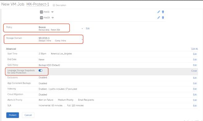
The newly configured protection job will perform its initial run immediately, unless it is currently within a blackout period, and the job will repeat itself according to the schedule set forth in the policy.
Recovery
Recovery jobs can be initiated to restore a virtual machine from the backed-up snapshots and return the virtual machine to service. A unique aspect of the Cohesity software is the sequence of the recovery process. When a recovery job is started, the Cohesity system will present an NFS-based datastore from itself, which is mounted to the ESXi host, inside of which are the virtual machine files that have been bloomed from the snapshots. The virtual machine will then be registered in vCenter from this location, and the virtual machine will be powered on. This process returns the recovered virtual machine to service much faster than typical recovery processes will since the virtual machine will immediately run with its virtual files sourced from the Cohesity NFS datastore. After the virtual machine is powered on, a storage vMotion will relocate the virtual machine files to their original location. The benefit of this recovery workflow is amplified when multiple simultaneous virtual machine recoveries are needed, because the time to return the virtual machines to service is very low, and the remaining process of relocating the virtual machines via storage vMotion happens in the background while the virtual machines are already online. A recovered virtual machine will have no snapshots, even if the virtual machine originally had snapshots at the time of the backup which is being restored.
Recovery jobs can be used to restore multiple virtual machines at one time, however there are two notable limitations to the restoration of multiple virtual machines. First, in order to restore multiple virtual machines in a single job, all of the virtual machines must have originated from the same source. Second, all of the virtual machines must have been backed up to the same Cohesity storage domain. For example, if some virtual machines are protected and targeted a storage domain using replication factor 2, meanwhile others were backup up to a storage domain using erasure coding, a single recovery job could only restore the virtual machines in the storage domain using replication factor 2 and could not recover the virtual machines in the storage domain using erasure coding. In order to recover both sets of virtual machines, two recovery jobs would need to be started. Similarly, if virtual machines originated from multiple sources then multiple jobs must be created to restore them.
Multiple recovery jobs can be created and run simultaneously when the above scenarios apply.
When multiple Cohesity systems are configured to replicate snapshots, once the first run of a Protection Job has completed and successfully replicated the snapshot data, a Recovery Job can be initiated at any time from either the original source Cohesity system, for example a Cohesity VE virtual machine, or from the receiving Cohesity system. This allows for a local Recovery Job to be started on the Cohesity VE system to restore one or more virtual machines using locally held data, for example restoring snapshots from the past week which would be stored by the Cohesity VE virtual machine, according to the local retention setting configured in the job’s policy. Alternatively, the Recovery Job can be started from the receiving Cohesity cluster to restore a copy of the virtual machine(s) from a snapshot that has aged off in the originating Cohesity VE system but is still retained in the larger cluster by policy. In a scenario where the originating Cohesity system has failed or is offline due to network or hardware problems, the Recovery Job must be run from the receiving Cohesity cluster, and the inactive job on the receiving cluster can be failed over, as outlined in the subsequent section.
To initiate a recovery operation, follow these steps:
1. Log into the Cohesity Dashboard web page.
2. From the Protection menu at the top of the screen, click Recovery.
3. Click the Recover button, from the drop-down list that appears, click virtual machines.
4. In the search field, search for the name of the virtual machine or virtual machines that need to be recovered. Wildcard characters can be used, and additional filters can be applied.
5. Check the checkbox next to the name(s) of the virtual machines you wish to recover.
6. Steps 4 and 5 can be repeated multiple times to select different virtual machines, for example searching for the name of one virtual machine, selecting it, then clearing the search field, searching for the name of another virtual machine, and then selecting that one as well.
7. When all the desired virtual machines have been selected, click Continue.
8. The pencil icon next to each virtual machine can be clicked to select the snapshot used as the recovery point. By default, the latest snapshot will be chosen. Choose the desired recovery point in the pop-up window and click Save.
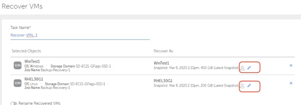
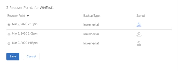
9. Optionally, toggle the radio button to choose to rename the recovered virtual machines.
10. Choose the option to recover the virtual machines to their original location, or to a new one. Recovery to a new location can only be done to a source already known by the Cohesity cluster, for example, a different vCenter server that is already configured as a source.
11. Choose the option to keep the networking configuration as it was originally configured, to leave the configuration but leave disconnected, or to leave the network detached.
12. Choose whether to power the recovered virtual machine on or to leave it powered off.
13. Click Finish.
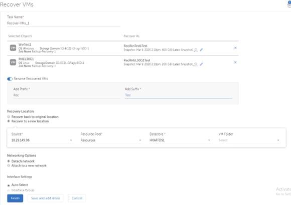
The recovery job will immediately start the recovery process and restore the virtual machines using the settings specified in the job.
Failover
Protection jobs which replicate snapshots to a remote Cohesity cluster will create a duplicate of the Protection Job on the receiving cluster, but that job will be marked as an inactive job. If the originating Cohesity system is failed or otherwise offline, this inactive job can be failed over to the receiving Cohesity cluster. This action of failing over the job will cause the originating job and the newly activated job to break their association, which will not allow for subsequent snapshots from the originating job to replicate to the receiving cluster any longer. Should the originating Cohesity system and job come back online, the local snapshot captures will resume, but replications will be rejected by the receiving system. Failing over an inactive job will also initiate a process to select a new source and policy for the activated job, and then proceed to starting a Recovery Job for all of the virtual machines from the original replicated job. Due to this behavior, a job failover is best used when a disaster has been declared at the originating site, and recovery of that site is not expected. Recovery of one or more virtual machines to the originating site while the originating Cohesity system is online can be done at any time with a normal Recovery Job.
To fail over a protection job and initiate recovery, follow these steps:
1. Log into the Cohesity Dashboard web page.
2. From the Protection menu, click Protection Jobs.
3. Identify the remote Protection Job, which is marked inactive, that needs to be failed over. Click the ellipses, then click Failover.
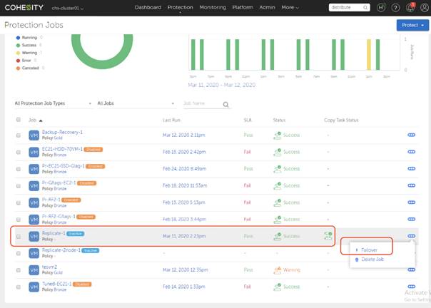
4. Select a new Source and Policy for the failed over job, then click Failover Job and Continue to Recovery.
The failover recovery job will automatically recovery all of the virtual machines in the original job. The pencil icon next to the virtual machines can be clicked to select the snapshot used as the recovery point. By default, the latest snapshot will be chosen. Choose the desired recovery point in the pop-up window and click Save. In the event of failover to a HyperFlex cluster, ensure to choose correct data store on the HyperFlex cluster
![]() In the event of failover to a HyperFlex cluster, ensure to choose correct data store on the HyperFlex cluster.
In the event of failover to a HyperFlex cluster, ensure to choose correct data store on the HyperFlex cluster.
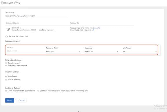
5. Optionally, toggle the radio button to choose to rename the recovered virtual machines.
6. Recovery will be performed to the source previously selected. Choose a resource pool, datastore and virtual machine folder for the recovered virtual machines.
7. Choose a new network port group to attach the virtual machines to, optionally you may leave the network disconnected, or to leave the network completely detached.
8. Choose whether to power the recovered virtual machines on, or to leave them powered off.
9. Click Finish.
Views
A Cohesity View provides network accessible storage distributed across the Cohesity cluster, as either NFS volumes, SMB/CIFS mount paths, or S3 compliant object-based storage. A view targets a specific Cohesity storage domain, taking advantage of the settings in that domain regarding compression, deduplication, encryption, and the efficiency derived from the choice between data replication or erasure coding. In order to mount a view, the client computer must reside in a whitelisted subnet. The views created support the following protocol specific settings and capabilities:
· NFS version 3.0 is supported, however NLM locking is not supported.
· NFS mounts and filenames only support ASCII and UTF-8 filenames.
· SMB versions 3.0 and 2.x are supported.
· DFS namespaces are supported, but DFS links are not given
· Only NTLMv2 authentication is supported. (Windows 2008 R2 and earlier by default only use LM and NTLM, and therefore must be modified)
· SMB shares are not automatically discoverable, however they will be found when browsing directly to the Cohesity cluster, for example: \\<Cohesity_cluster_name> or \\<Cohesity_cluster_VIP>
· In order to define SMB share file and folder level ownership and permissions, the Cohesity cluster must be added to a Microsoft Active Directory domain. Without Active Directory integration, all shares give full control to everyone.
Creating a view that contains all 3 protocols results in an S3 view that is read only. In order to create an S3 compliant view that has read/write capabilities, create a view that uses only the S3 protocol.
To create a view, follow these steps:
1. Log into the Cohesity Dashboard web page.
2. From the Platform menu at the top of the screen, click Views.
3. Click Create View.
4. Enter a name for the new View, and optionally enter a description.
5. Select the desired Storage Domain from the drop-down list.
6. Select the QoS Policy for this view from the dropdown list. Options include:
- Backup Target SSD: The Cluster sends sequential and random I/Os to SSD. There by, lower latency than other Backup Target QoS Policy
- TestAndDev High: The same as TestAndDev Low, except that , at times of contention, the I/Os with this QoS policy are given higher priority compared to I/Os with TestAndDev Low
- TestAndDev Low: In this policy, Data is written to SSD and has lower latency compared to Backup Target SSD.
- Backup Target High: The Cluster generally sends sequential data to HDD and random writes to SSD.
- Backup Target Low: The same as Backup Target High except that the priority for processing workloads with this policy is lower than workloads with Backup Target High.
![]() Irrespective of the QoS Policy used, files stored in Cohesity views are eventually down tiered to hard drives.
Irrespective of the QoS Policy used, files stored in Cohesity views are eventually down tiered to hard drives.
7. Click the Show Advanced Settings link to expand the list of options available.
8. Select the protocol(s) to be used for this View by clicking the appropriate radio button.
9. Modify the additional options for the view being created as necessary. Some options are not available by default, for example setting specific SMB share ownership and default permissions is not available unless the Cohesity cluster has been joined to an Active Directory domain.
10. Click Create View.
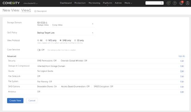
Shares
When a new View is created, the name of the View is the default mount path for the clients, and this mount path will establish the top of the file tree. Additional Shares can be created which directly target subfolders within the file tree for ease of navigation. For example, a View can be created for a company division, and then subfolders for each department can be created, each with their own share. End users could navigate to the top of the tree by using the division share or navigate and map directly to their department share.
To create an additional share within a View, follow these steps:
1. Log into the Cohesity Dashboard web page.
2. From the Platform menu at the top of the screen, click Views.
3. Click the ellipses next to the View you wish to modify, then click View Details.
4. Underneath the Shares & Mount Paths section, click Create Share.
5. Navigate the file tree to the folder where you wish for the new Share to be.
6. Enter a name for the new Share then click Create Share.
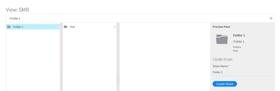
Global Whitelist
A Global Whitelist is configured to allow all clients which match the IP subnet to access all Views created in the Cohesity cluster. In addition to the Global Whitelist, the whitelist settings can be modified individually in the Advanced Settings of each View.
To modify the Global Whitelist, follow these steps:
1. Log into the Cohesity Dashboard web page.
2. From the Platform menu at the top of the screen, click Views.
3. Click SMB Authentication & Global Whitelist tab.
4. Enter an IP subnet and a subnet mask to add to the Global Whitelist and optionally enter a description.
5. Click Add.
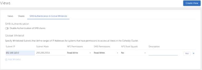
Shares
When a new View is created, the name of the View is the default mount path for the clients, and this mount path will establish the top of the file tree. Additional Shares can be created which directly target subfolders within the file tree for ease of navigation. For example, a View can be created for a company division, and then subfolders for each department can be created, each with their own share. End users could navigate to the top of the tree by using the division share or navigate and map directly to their department share.
To create an additional share within a View, follow these steps:
1. Log into the Cohesity Dashboard web page.
2. From the Platform menu at the top of the screen, click Views.
3. Click the ellipses next to the View you wish to modify, then click View Details.
4. Underneath the Shares & Mount Paths section, click Create Share.
5. Navigate the file tree to the folder where you wish for the new Share to be.
6. Enter a name for the new Share then click Create Share.
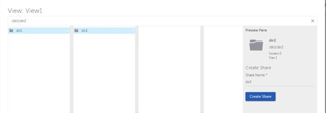
View Protection
Views can also be protected by View Jobs similar to the way virtual machines are protected via Protection Jobs. View protection targets the same Storage Domain configured for the Cohesity View and will operate according to the same configured Policies as do Protection Jobs.
To configure protection of a Cohesity View, follow these steps:
1. Log into the Cohesity Dashboard web page.
2. From the Platform menu, click Views.
3. Click the ellipses next to the View you wish to back up then click Protect View.
4. Enter a name for the View Job, and optionally enter a description.
5. Choose a Policy from the drop-down list.
6. Click Protect.
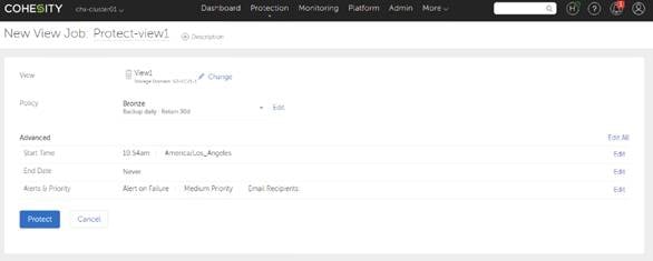
View Recovery
Unlike a Recovery Job for a virtual machine, which regenerates the virtual machine from the backed-up snapshots, recovery of files from within a View involves creating a Recovery Job, which actually allows you to browse the file tree to locate the file(s) you need to recover. The files can then be downloaded and manually put back into their original locations by the administrative staff.
To recover files from a View snapshot, follow these steps:
1. Log into the Cohesity Dashboard web page.
2. From the Protection menu at the top of the screen, click Recovery.
3. Click the Recover button, from the drop-down list that appears, click Files or Folders.
4. Click the radio button for Browse or Specify Path.
5. Enter the name of the View for which you need to recover files in the search field.
6. When the protected View appears, click the name of the View.
7. From the pop-up window that appears, navigate the file tree until you locate the file(s) you need to recover. Click the file, then click Download File.
8. After all the necessary files have been downloaded locally to your computer, click Close.
9. Manually copy the downloaded file(s) to their original location the Cohesity View’s file tree.
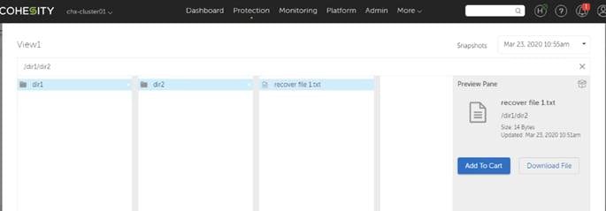
Test/Dev
An additional feature of the Cohesity software is the ability to rapidly clone virtual machines for testing or development purposes. A cloned virtual machine is functionally a restored copy of a snapshot point in time of that virtual machine, and not a clone of the currently running virtual machine. A virtual machine which is cloned using the Cohesity dashboard runs with its virtual machine files and virtual disk files stored in an NFS datastore, which is temporarily mounted by two of the VMware hosts from the Cohesity cluster nodes. Because the virtual machine runs directly from the Cohesity cluster, this use case is appropriate for functional testing, end-user acceptance, and software development or debugging activities, where performance is a secondary consideration. The Clone virtual machines task gives the administrator the opportunity to rename the cloned virtual machine, clone it to another registered source, and change the network in which the virtual machine is attached. In most cases, manual reconfiguration of the virtual machines network configuration would be necessary after the clone is created, assuming the virtual machines use static IP addressing, in order to avoid address conflicts.
To clone a virtual machine for Test/Dev use, follow these steps:
1. Log into the Cohesity Dashboard web page.
2. From the More menu at the top of the screen, click Test & Dev.
3. Click the Clone button, from the drop-down list that appears, click virtual machines.
4. In the search field, search for the name of the virtual machine or virtual machines that need to be recovered. Wildcard characters can be used, and additional filters can be applied.
5. Check the checkbox next to the name(s) of the virtual machines you wish to recover.
6. Steps 4 and 5 can be repeated multiple times to select different virtual machines, for example searching for the name of one virtual machine, selecting it, then clearing the search field, searching for the name of another virtual machine, and then selecting that one as well.
7. Once all the desired virtual machines have been selected, click Continue.
8. To rename the cloned virtual machine, toggle the switch for Rename Cloned virtual machines, then enter a prefix or suffix to add to the name of the virtual machine.
9. Select the Source from the drop-down list in order to pick the location to clone the virtual machine. The Resource Pool drop-down list will list the hosts or clusters available. The virtual machine Folder will list the available folders to place the virtual machine into. Finally, the View field represents the name of the NFS datastore from the Cohesity cluster which will be mounted to the VMware hosts.
10. Choose to either leave the networking detached in order to perform manual reconfiguration or click the radio button for Attach to a new network and choose the virtual machine port group to attach the cloned virtual machine to.
11. Choose to leave the virtual machine powered off, or to power it on after the task completes.
12. Click Finish.
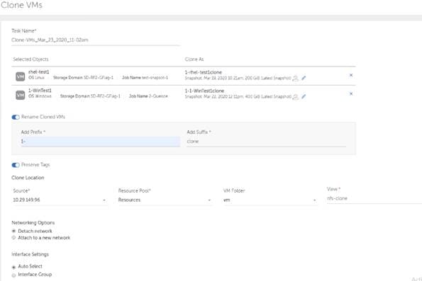
To tear down and delete cloned virtual machines when they are no longer needed, follow these steps:
1. Log into the Cohesity Dashboard web page.
2. From the More menu at the top of the screen, click Test & Dev.
3. From the list of clone jobs presented, click the name of the clone job that created the clone that you wish to remove.
4. Click Tear Down Clone.
5. Click the Yes, tear down button in the pop-up window that appears.
Monitoring
The Cohesity software offers numerous options for passive and proactive monitoring of the cluster, including job status, performance, hardware status, storage capacity and more.
Dashboard
The Dashboard screen in the Cohesity HTML management webpage provides a useful overview of the status of the overall system health, backup job runs, storage efficiency and performance over the past 24 hours. The dashboard allows the Cohesity administrator to see at a quick glance if any items need attention.
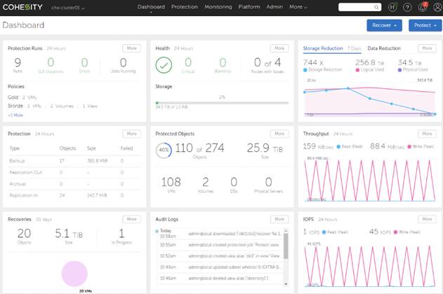
Performance
Under the Monitoring menu, the Performance screen can be used to view the storage I/O per second (IOPS), latency and throughput, plus the CPU and memory usage of the nodes in the Cohesity cluster. Views can be modified to see figures for the entire cluster, individual nodes, or individual Storage Domains. The view timeframe can be modified, and the view can be zoomed in for greater detail.
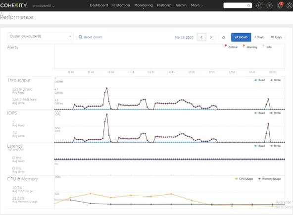
Alerts
Alerts in the Cohesity cluster can be viewed under the Monitoring menu by clicking Alerts. Alerts can be configured to automatically send a notice to an email recipient as well.
To configure alerts to be sent to an email recipient, follow these steps:
1. Log into the Cohesity Dashboard web page.
2. From the Monitoring menu, click Alerts.
3. Click the Edit Alert Settings button.
4. Enter the email address of the recipient then click Add to List.
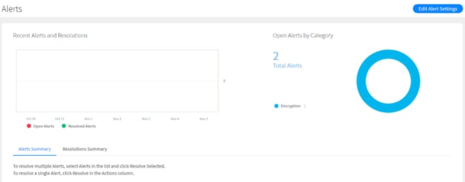
Storage
Under the Monitoring menu, clicking Storage will show a page detailing the storage space consumption in the Cohesity cluster, plus the data reduction efficiency figures due to deduplication and compression. The views in the charts can target the entire cluster or individual Storage Domains, and the timeframe for the charts can be customized.
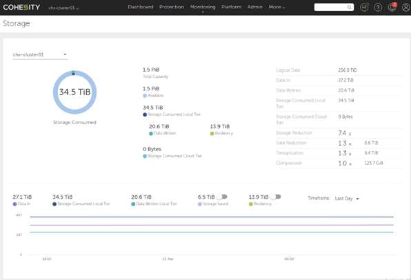
Reports
From the Monitoring menu, click Reports to view dynamic reports which can be generated for viewing, exporting, and also as regular emails. There are several report types available, such as backup snapshot summaries, backup job status, cluster health and storage, and many more. Reports can be tailored to show specific date ranges, sources, and statuses, and then configured to be regularly sent via email by clicking the email clock link. Note that not all reports can be configured to send automatically via email.
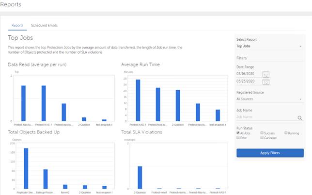
SMTP
In order to send alerts and/or scheduled reports to recipients via email, the Cohesity cluster’s SMTP settings must be enabled.
To enable SMTP email alerts and reports, follow these steps:
1. Log into the Cohesity Dashboard web page.
2. From the Admin menu at the top of the screen, click Cluster Settings.
3. Enter a system administrator email address which represents this Cohesity cluster, this will be the “From:” address for outgoing emails.
4. Toggle the switch to Enable SMTP Server.
5. Enter the SMTP server information as appropriate for your environment.
6. Toggle the switch to Test Email on Save.
7. Click Save.
SNMP
If necessary, SNMP traps can be sent to an SNMP receiver for parsing by a network management system. In the Monitoring > SNMP menu, click Edit to enable and configure SNMP traps, their destination, and the trap user.
Remote Support
Cohesity offers a remote support service named Support Channel, which is enabled by default. Support Channel initiates outgoing sessions to register the Cohesity system with Cohesity’s Support Channel server and technical support team. Cohesity support staff can securely connect and log into the cluster remotely for on-demand technical support and troubleshooting using SSH and secure keys. In some cases, Support Channel connections may require the use of a proxy server to function properly.
Helios
Helios is Cohesity's SaaS-based management platform that provides a single view and global management of all your Cohesity clusters, whether on-premises, cloud, or Virtual Edition, regardless of cluster size. You can quickly connect clusters to Helios and then access them from anywhere using an internet connection and your Cohesity Support Portal credentials.
For more details on Helios , see: About Helios
To connect to Helios, follow these steps:
1. Sign into the cluster that you want to connect to Helios.
2. In the Cohesity Dashboard, as a user with Admin privileges, click the Helios icon in the top right corner of the Dashboard and then click Enable Helios.
3. Access Permission: If you want read-only access to the cluster in Helios, toggle on View Only. Otherwise you will have Admin privileges when accessing the cluster in Helios.
4. Connect to Helios: Toggle on Enable. The Helios portal page is displayed.
5. Enter your Cohesity Support Portal credentials.
6. If the connection fails, make sure you have an internet connection and try to connect again.
7. When the cluster is connected to Helios, a green check mark is displayed in Helios icon in the top right corner of the Cohesity Dashboard.
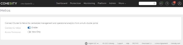
Test Plan
Numerous scenarios were developed to rigorously test the integration between the Cohesity systems and Cisco HyperFlex, and also to test the redundancy and durability of the Cohesity system running within the Cisco UCS domain. All of the tests below were executed in Cisco’s labs, using complaint hardware and software as listed previously, and configured according to the instructions in this document. Tests executed included, but were not limited to the following:
Installation
· Creation and application of Cohesity specific UCS policies and service profiles.
· Successful installation and initial configuration of Cohesity 6.3.1c software on Cisco UCS managed S Series Storage server hardware.
Core Functional Testing
· Enable Cohesity Storage Snapshot Provider features.
· Configure multiple Cisco HyperFlex clusters as Storage Snapshot Provider sources.
· Configure multiple VMware vCenter systems as sources which manage both single and multiple Cisco HyperFlex clusters.
· Configure and run Protection Jobs backing up virtual machines from multiple Cisco HyperFlex clusters.
· Replication Job from multiple HyperFlex Edge clusters to primary Cohesity S3260 cluster
· Configure and run Protection for NAS volumes
· Configure and run a large-scale Protection Job, protecting ~100 virtual machines which generate random data.
· Configure and run Restore Jobs restoring virtual machines across multiple Cisco HyperFlex clusters.
· Configure Cohesity Views providing NFS, SMB and S3 compliant file services.
· Configure Test/Dev clones of virtual machines for temporary use.
Extended Functional Testing
· Backup and restore virtual machines to/from multiple Cisco HyperFlex deployment types, including traditional Hybrid clusters and All-Flash clusters.
· Backup and restoration of virtual machines running on Cisco HyperFlex version 4.01b.
· Configure Remote Cluster pairing and replication of snapshots between multiple Cohesity systems.
· Configure a NetApp FAS array as source for volume Backup on Cohesity Cluster
· Backup virtual machines using a mixture of jobs with the Storage Snapshot integration both enabled, and disabled.
· Backup of virtual machines without existing snapshots and also with existing VMware standard snapshots or existing HyperFlex native snapshots.
· Restore virtual machines that had no previously existing snapshots, and also with previously existing VMware standard snapshots and HyperFlex native snapshots.
· Restore virtual machines to Cisco HyperFlex clusters that were not the original location of the virtual machines.
· Configure and test SMTP alerts and reporting.
· Configure and run Projection jobs from Cohesity Helios
Failover and Redundancy Testing
· All failover and redundancy tests were conducted while at least one active Cohesity Protection Job was running.
· Fail the active network path for one Cohesity node.
· Fail all the network uplinks from a single Fabric Interconnect.
· Fail the active side Fabric Interconnect.
· Ungraceful shut down the Storage Controller VM (SCVM) of one HyperFlex node.
· Ungraceful shut down of one HyperFlex node, causing virtual machines to restart via VMware High Availability.
Performance Testing
Several Performance tests were run on Cohesity S3260 4-node cluster. To achieve optimal performance of Cohesity DataPlatform on Cisco UCS S3260 cluster, different tunings parameters were altered on Cohesity cluster. In the event customers are facing sub-optimal performance on Cohesity cluster, please contact Cohesity support to identify tunings parameters vis-à-vis customer workload and Cohesity DataPlatform release. Some of the key performance test executed on the existing deployment are explained below:
· Data Protection jobs for non-compressible data on 12 to 72 VMs hosted on HyperFlex All flash Cluster
· NFS File Services test for reading, creating and appending files of 1 MB to 10 MB. This included scalability testing of cohesity cluster from single to four node system. The Reads were of 100 KB block size, append and create file was through 8 KB block size.
· Video Services test for removing creating and reading large video files of 100 MB. This included scalability testing of cohesity cluster from single to four node system. The Reads were of 256 KB block size and video creation was through 1MB block size.
Below is an example Bill of Materials used to order four (4) of the Cisco UCS S3260 Storage servers, which are compliant with the requirements to run the Cohesity DataPlatform software, along with the pair of Cisco Fabric Interconnects, and the 25 GbE cables to connect them, as used in the testing and reference design outlined in this document.
Table 32 Cohesity on Cisco UCS Sample Bill of Materials
| Line Number |
Item Part Number |
Item Description |
Quantity |
| 1.0 |
UCSS-S3260 |
Cisco UCS S3260 Storage Server Base Chassis |
4 |
| 1.1 |
CON-SNT-UCSS3260 |
SNTC 8X5XNBD, Cisco UCS S3260 Storage Server Base Chassis |
4 |
| 1.1 |
UCS-C3K-3XTSSD32 |
Cisco UCS C3000 Top Load 3X 3.2TB SSD |
16 |
| 1.2 |
UCSC-PSU1-1050W |
Cisco UCS 1050W AC Power Supply for Rack Server |
16 |
| 1.3 |
CAB-N5K6A-NA |
Power Cord, 200/240V 6A North America |
16 |
| 1.4 |
CIMC-LATEST |
IMC SW (Recommended) latest release for C-Series Servers. |
4 |
| 1.5 |
N20-BKVM |
KVM local IO cable for UCS servers console port |
4 |
| 1.6 |
N20-BBLKD-7MM |
UCS 7MM SSD Blank Filler |
8 |
| 1.7 |
UCSC-C3X60-SBLKP |
UCS C3x60 SIOC blanking plate |
4 |
| 1.8 |
UCSC-C3X60-RAIL |
UCS C3X60 Rack Rails Kit |
4 |
| 1.9 |
UCSS-S3260-BBEZEL |
Cisco UCS S3260 Bezel |
4 |
| 1.10 |
UCS-S3260-M5SRB |
UCS S3260 M5 Server Node for Intel Scalable CPUs |
4 |
| 1.11 |
UCS-CPU-I6240 |
Intel 6240 2.6GHz/150W 18C/24.75MB DCP DDR4 2933 MHz |
8 |
| 1.12 |
UCS-MR-X32G2RS-H |
32GB DDR4-2666-MHz RDIMM/PC4-21300/dual rank/x4/1.2v |
32 |
| 1.13 |
UCS-S3260-DHBA |
UCS S3260 Dual Pass Through based on LSI 3316 |
4 |
| 1.14 |
UCS-S3260-M5HS |
UCS S3260 M5 Server Node HeatSink |
8 |
| 1.15 |
UCS-S3260-PCISIOC |
UCS S3260 PCIe SIOC |
4 |
| 1.16 |
UCSC-PCIE-C25Q-04 |
Cisco UCS VIC 1455 Quad Port 10/25G SFP28 CNA PCIE |
4 |
| 1.17 |
UCSC-LP-C25-1485 |
Low profile bracket for VIC |
4 |
| 1.18 |
UCS-C3K-42HD10 |
UCS C3X60 3 row of 10TB NL-SAS drives (42 Total) 420TB |
4 |
| 1.19 |
UCSC-C3X60-10TB |
UCSC C3X60 10TB 4Kn for Top-Load |
168 |
| 1.20 |
UCSC-C3K-M4IO |
Cisco UCS S3260 I/O Expander for M4/M5 Server Node |
4 |
| 1.21 |
UCS-S3260-G3SD24 |
UCS S3260 240G Boot SSD (Micron 6G SATA) |
8 |
| 2.0 |
UCS-FI-6454-U |
UCS Fabric Interconnect 6454 |
4 |
| 2.1 |
N10-MGT016 |
UCS Manager v4.0 |
4 |
| 2.2 |
UCS-FAN-6332 |
UCS 6332/ 6454 Fan Module |
16 |
| 2.3 |
UCS-ACC-6332 |
UCS 6332/ 6454 Chassis Accessory Kit |
4 |
| 2.4 |
UCS-PSU-6332-AC |
UCS 6332 Power Supply/100-240VAC |
8 |
| 2.5 |
CAB-C13-CBN |
Cabinet Jumper Power Cord, 250 VAC 10A, C14-C13 Connectors |
8 |
| 3.0 |
SFP-25G-AOC3M= |
25GBASE Active Optical SFP28 Cable, 3M |
16 |
Cohesity Certified Cisco UCS Nodes
The present solution explains the configuration of Cisco UCS S3260 storage server with Cohesity DataPlatform. Besides the present Cisco UCS S3260 Storage Server configuration, Cisco and Cohesity have certified solutions with different capacity points available on Cisco UCS C Series Rack Servers and Cisco UCS S3260 Storage servers. This allows customers to select their configuration based on key characteristics such as
· Total Capacity
· Workload configurations such as Data Protection and File Services
· Performance requirements based on Cisco UCS C220 M5 All Flash or HDD configurations.
· Single node deployments for Remote offices and Branch offices (ROBO)
· Heterogenous configuration with mix of Cisco UCS S3260 storage sever, Cisco UCS C240 M5 LFF Rack servers, Cisco UCS C220 M5 LFF Rack Servers.
Table 33 lists the Cohesity certified nodes on Cisco UCS Platform.
Table 33 Cohesity Certified Cisco UCS Nodes
| Solution Name |
Cisco UCS Platform |
Capacity per Node |
Caching SSDs/NVMe per Node
|
| Cohesity-C220-12TB-24TB-36TB-Nodes |
Cisco UCS C220 M5 LFF Rack Server |
12 TB |
1.6 TB |
| 24 TB |
1.6 TB |
||
| 36 TB |
1.6 TB |
||
| Cohesity-C240-48TB-and-120TB-Nodes |
Cisco UCS C240 M5 LFF Rack Server |
48 TB |
3.2 TB |
| 120 TB |
6.4 TB |
||
| Cohesity-C220-ROBO-8TB-and-16TB-Nodes |
Cisco UCS C220 M5 LFF Rack Server |
8 TB |
1920 GB |
| 16 TB |
1920 GB |
||
| Cohesity-C220-All-NVMe-Nodes |
Cisco UCS C220 M5 All NVMe Rack Server |
76 TB |
|
| Cohesity-S3260-120TB-420TB-700TB-Node |
Cisco UCS S3260 M5 Storage Server |
210 TB |
12.8 TB |
| 420 TB |
12.8 TB |
Primary data can be loosely defined as the latency-sensitive information required for companies to do business. Non-latency-sensitive data includes backup and recovery, files and objects, test and dev, archive, and analytics. Both types of data are growing exponentially, are becoming harder to store, protect and access. Much of it, particularly non-latency-sensitive data, is buried or stored in silos. And, both types of data are becoming more critical for meeting business objectives. To meet compliance and regulatory requirements and to more cost-effectively store, protect and provide business applications with the right data development, test and analysis, companies need to modernize their data center operations. Hyperconvergence has been key in replacing slow, siloed data center systems with scale-out software-defined platforms on enterprise-class x86 servers with a pay-as-you-grow model.
Cisco HyperFlex and the Cohesity DataPlatform on Cisco UCS are modern, hyper-converged platforms for managing both latency-sensitive and non-latency-sensitive workloads, respectively. These two industry-leading platforms are integrated to deliver an agile web-scale solution, for on-premises and cloud, that easily scales with customer’s business needs, consolidates IT operations for all workloads, brings frictionless mobility to data and applications from edge to core to cloud, and puts data to work. With the Cisco-Cohesity integrated solution, hyperconvergence meets hyperconvergence. It means customers can easily unify, protect, access, and control their data across clouds, data centers or remote and branch offices at significant cost savings compared to traditional alternatives.
For data center/cloud compute and storage buyers who need radically simplified data management with productive data across locations, Cohesity’s software-defined web-scale platform on Cisco UCS provides a single solution for data management—starting with backups and extending to disaster recovery, file and object services, dev/test, and analytics. Unlike legacy point products and cobbled-together solutions that result in mass data fragmentation, only the joint Cisco-Cohesity solution redefines data management with powerful simplicity, radical flexibility, and unlocked value for hybrid/multi-cloud IT that keeps all of data protected and productive within a single, unified architecture on Cisco UCS. Cisco HyperFlex complements Cohesity DataPlatform on Cisco UCS for an integrated solution that offers hyperconverged simplicity, multi-cloud agility, and global efficiency and visibility across 100% of your data.
Cisco is a Cohesity investor, validated design partner, reseller, support partner, and customer. For more information, visit https://www.cohesity.com/products/cisco/.
Anil Dhiman, Technical Marketing Engineer, Cisco Unified Computing Systems, Cisco Systems, Inc.
Anil Dhiman has nearly 20 years of experience specializing in Data Center solutions on Cisco UCS servers, and Performance Engineering of large-scale enterprise applications. Over the past 10 years, Anil has authored several Cisco Validated Designs for Enterprise Solutions on Cisco Data Center Technologies. Currently, Anil's focus is on Cisco’s portfolio of Hyperconverged Infrastructure and Data Protection Solutions.
Acknowledgements
For their support and contribution to the design, validation, and creation of this Cisco Validated Design, the author would like to thank:
· Jawwad Memon, Product Manager, Cisco Systems, Inc.
· Damien Philip, Principal Solutions Architect, Cohesity
· Sanjeev Desai, Senior Director, Solutions Marketing, Cohesity