Cisco HyperFlex for Google Cloud’s Anthos
Available Languages
Bias-Free Language
The documentation set for this product strives to use bias-free language. For the purposes of this documentation set, bias-free is defined as language that does not imply discrimination based on age, disability, gender, racial identity, ethnic identity, sexual orientation, socioeconomic status, and intersectionality. Exceptions may be present in the documentation due to language that is hardcoded in the user interfaces of the product software, language used based on RFP documentation, or language that is used by a referenced third-party product. Learn more about how Cisco is using Inclusive Language.
- US/Canada 800-553-2447
- Worldwide Support Phone Numbers
- All Tools
 Feedback
 Feedback

Cisco HyperFlex for Google Cloud’s Anthos
Cisco HyperFlex with HX-CSI Plugin for Google Cloud’s Anthos GKE on-prem Deployment
Published: May 2020


About the Cisco Validated Design Program
The Cisco Validated Design (CVD) program consists of systems and solutions designed, tested, and documented to facilitate faster, more reliable, and more predictable customer deployments. For more information, go to:
http://www.cisco.com/go/designzone.
ALL DESIGNS, SPECIFICATIONS, STATEMENTS, INFORMATION, AND RECOMMENDATIONS (COLLECTIVELY, "DESIGNS") IN THIS MANUAL ARE PRESENTED "AS IS," WITH ALL FAULTS. CISCO AND ITS SUPPLIERS DISCLAIM ALL WARRANTIES, INCLUDING, WITHOUT LIMITATION, THE WARRANTY OF MERCHANTABILITY, FITNESS FOR A PARTICULAR PURPOSE AND NONINFRINGEMENT OR ARISING FROM A COURSE OF DEALING, USAGE, OR TRADE PRACTICE. IN NO EVENT SHALL CISCO OR ITS SUPPLIERS BE LIABLE FOR ANY INDIRECT, SPECIAL, CONSEQUENTIAL, OR INCIDENTAL DAMAGES, INCLUDING, WITHOUT LIMITATION, LOST PROFITS OR LOSS OR DAMAGE TO DATA ARISING OUT OF THE USE OR INABILITY TO USE THE DESIGNS, EVEN IF CISCO OR ITS SUPPLIERS HAVE BEEN ADVISED OF THE POSSIBILITY OF SUCH DAMAGES.
THE DESIGNS ARE SUBJECT TO CHANGE WITHOUT NOTICE. USERS ARE SOLELY RESPONSIBLE FOR THEIR APPLICATION OF THE DESIGNS. THE DESIGNS DO NOT CONSTITUTE THE TECHNICAL OR OTHER PROFESSIONAL ADVICE OF CISCO, ITS SUPPLIERS OR PARTNERS. USERS SHOULD CONSULT THEIR OWN TECHNICAL ADVISORS BEFORE IMPLEMENTING THE DESIGNS. RESULTS MAY VARY DEPENDING ON FACTORS NOT TESTED BY CISCO.
CCDE, CCENT, Cisco Eos, Cisco Lumin, Cisco Nexus, Cisco StadiumVision, Cisco TelePresence, Cisco WebEx, the Cisco logo, DCE, and Welcome to the Human Network are trademarks; Changing the Way We Work, Live, Play, and Learn and Cisco Store are service marks; and Access Registrar, Aironet, AsyncOS, Bringing the Meeting To You, Catalyst, CCDA, CCDP, CCIE, CCIP, CCNA, CCNP, CCSP, CCVP, Cisco, the Cisco Certified Internetwork Expert logo, Cisco IOS, Cisco Press, Cisco Systems, Cisco Systems Capital, the Cisco Systems logo, Cisco Unified Computing System (Cisco UCS), Cisco UCS B-Series Blade Servers, Cisco UCS C-Series Rack Servers, Cisco UCS S-Series Storage Servers, Cisco UCS Manager, Cisco UCS Management Software, Cisco Unified Fabric, Cisco Application Centric Infrastructure, Cisco Nexus 9000 Series, Cisco Nexus 7000 Series. Cisco Prime Data Center Network Manager, Cisco NX-OS Software, Cisco MDS Series, Cisco Unity, Collaboration Without Limitation, EtherFast, EtherSwitch, Event Center, Fast Step, Follow Me Browsing, FormShare, GigaDrive, HomeLink, Internet Quotient, IOS, iPhone, iQuick Study, LightStream, Linksys, MediaTone, MeetingPlace, MeetingPlace Chime Sound, MGX, Networkers, Networking Academy, Network Registrar, PCNow, PIX, PowerPanels, ProConnect, ScriptShare, SenderBase, SMARTnet, Spectrum Expert, StackWise, The Fastest Way to Increase Your Internet Quotient, TransPath, WebEx, and the WebEx logo are registered trademarks of Cisco Systems, Inc. and/or its affiliates in the United States and certain other countries.
All other trademarks mentioned in this document or website are the property of their respective owners. The use of the word partner does not imply a partnership relationship between Cisco and any other company. (0809R)
© 2020 Cisco Systems, Inc. All rights reserved.
About the Anthos Ready Partner Initiative
Anthos Ready designates Partner solutions that meet Google Cloud’s qualification requirements and have been verified to work with Anthos to meet the infrastructure and application development needs of enterprise customers. Partner solutions that complete and maintain the applicable qualification requirements are awarded the Works with Anthos badge which may be used with the qualified solution.
https://cloud.google.com/partners/anthos-ready
Table of Contents
Cisco Unified Computing System
Cisco UCS 6332-16UP Fabric Interconnect
Cisco HyperFlex HX-Series Nodes
Cisco HyperFlex HXAF240c-M5SX All-Flash Node
Cisco VIC 1387 MLOM Interface Cards
Cisco HyperFlex Data Platform Software
Cisco HyperFlex Connect HTML5 Management Web Page
Cisco HyperFlex HX Data Platform Administration Plug-in
Cisco HyperFlex HX Data Platform Controller
Data Operations and Distribution
Data Write and Compression Operations
Data Destaging and Deduplication
Cisco HyperFlex CSI Storage Plugin
Continuous Integration / Continuous Delivery with Anthos
Google Cloud Marketplace for Kubernetes Apps
Anthos GKE on-prem Network Topology
Deployment Hardware and Software
Cisco HyperFlex Cluster Configuration
Deploy Cisco HyperFlex Data Platform Installer VM
Cisco HyperFlex Cluster Creation
Run Cluster Post Installation Script
Adding a Converged Node through HX Installer
Upgrade Cisco HyperFlex Data Platform
Anthos GKE on-prem Prerequisites
L4 Load Balancer Configuration
Configuring Private Docker Repository
Setting up Proxy Environment (optional)
Configuring Static IPs for Admin and User Cluster
Creating Cluster Configuration File
Prepare Cluster with Configuration File
Create Cluster with Configuration file
Deploy Additional User Cluster
Enabling Ingress for L4 Load Balancer
Enabling Access to User Clusters with Google Cloud Console
Google Cloud Platform Marketplace
Installing HX-CSI Storage Plugin
Enabling Kubernetes Integration in Cisco HyperFlex Connect
Installing the Cisco HyperFlex CSI Plugin for Kubernetes
Verifying Cisco HyperFlex CSI Storage Class Creation
Installing AppDynamics for Monitoring Anthos GKE on-prem Cluster
Prerequisites for Cluster Agent Deployment
Monitor Demo Application Deployed on Anthos GKE on-prem cluster
Stateful Application Deployment
Sizing Considerations for Anthos GKE on Cisco HyperFlex
Appendix – Stateful Application YAML Examples
Stateful Application Deployment
Stateful Application for Scale Test
As enterprises undergo digital transformation, customers are modernizing their IT infrastructure to provide the performance, availability, scalability, and agility required to meet today's business demands. HyperConverged Infrastructure (HCI), the software-defined storage platform, has been the fastest growing platform providing an excellent fit for such growing business needs.
Cisco HyperFlex™ unifies compute, storage, and networking from the core to the edge. Cisco HyperFlex provides best-in-class HyperConverged Infrastructure that dramatically simplifies IT needs by providing a common building block for virtualized as well as Kubernetes-based workloads.
Google Cloud’s Anthos is an open hybrid and multi-cloud application platform that enables users to modernize existing applications, and build new ones, while running anywhere in a secure manner. Built on open source technologies pioneered by Google—including Kubernetes, Istio, and Knative—Anthos enables consistency between on-premises and cloud environments and helps accelerate application development. Included in Anthos is, GKE on-prem which helps business to modernize on-prem and transition to cloud with hybrid architectures, promoting agility and innovation.
By bringing together Anthos and Cisco HyperFlex hyperconverged infrastructure, customers can unlock new levels of speed and agility by simplifying the building, running and managing of modern applications in a Hybrid Cloud environment. By running Anthos on Cisco HyperFlex enables independent scaling of compute and storage, provides guaranteed performance and a simplified management. This solution enables users to quickly deploy and manage Kubernetes-based applications on Cisco HyperFlex or on the Cloud.
Kubernetes Monitoring with Cisco’s AppDynamics (optional component) gives organizations visibility into application and business performance, providing unparalleled insights into containerized applications, Kubernetes clusters and underlying infrastructure metrics—all through a single pane of glass.
This document details the deployment steps and best practices for this solution.
Introduction
HyperConverged Infrastructures coalesce the computing, memory, hypervisor, and storage devices of servers into a single platform of virtual servers. There is no longer a separate storage system, since the servers running the hypervisors also provide the software defined storage resources to store the virtual servers, effectively storing the virtual machines on themselves. Here are benefits:
· The silos are gone
· HCI is self-contained
· Simpler to use, faster to deploy, easier to consume
· Flexible and with high performance
The Cisco HyperFlex Kubernetes CSI Integration allows Cisco HyperFlex to dynamically provide persistent storage to stateful containerized workloads (from Kubernetes version 1.13 or later). The integration enables orchestration of the entire Persistent Volume object lifecycle to be offloaded and managed by Cisco HyperFlex, while being driven (initiated) by developers and users through standard Kubernetes Persistent Volume Claim objects. Developers and users get the benefit of leveraging Cisco HyperFlex for their Kubernetes persistent storage needs with zero additional administration overhead from their perspective. The HyperFlex Container Storage Interface (CSI) plug-in extends the performance, efficiency, and resiliency of HyperFlex to Kubernetes stateful applications.
Anthos GKE on-prem deployed on Cisco HyperFlex provides Container-as-a-Service environment with Anthos version 1.2 or higher. Cisco HyperFlex is qualified as an Anthos Ready Platform. This solution provides end-to-end orchestration, management and scalable architecture to deploy Anthos on Cisco HyperFlex with HyperFlex CSI (Container Storage Interface) for persistent storage to the containerized workloads. The HyperFlex CSI driver is qualified by Google as well. Also, in this solution we have included Cisco AppDynamics as it provides application visibility needed to deliver flawless customer experience for monitoring the containerized workloads running on Anthos GKE on-prem and cloud. The solution shows easy integration of AppDynamics with lightweight monitoring agents.
Audience
The intended audience for this document includes, but is not limited to, sales engineers, field consultants, professional services, IT managers, partner engineering, customers deploying the Cisco HyperFlex System and Anthos. External references are provided wherever applicable, but readers are expected to be familiar with VMware specific technologies, infrastructure concepts, networking connectivity, and security policies of the customer installation.
Purpose of this Document
This document describes the steps required to deploy, configure, and manage a standard Cisco HyperFlex system (in other words, a Cisco HyperFlex cluster connected to Cisco UCS Fabric Interconnects) to support Anthos. The document is based on all known best practices using the software, hardware and firmware revisions specified in the document at the time of publication. This document showcases the installation, configuration and expansion of Cisco HyperFlex standard clusters with converged nodes, and deployment of Anthos GKE on-prem in a typical customer datacenter environment. While readers of this document are expected to have sufficient knowledge to install and configure the products used, configuration details that are important to the deployment of this solution are provided in this solution.
Solution Summary
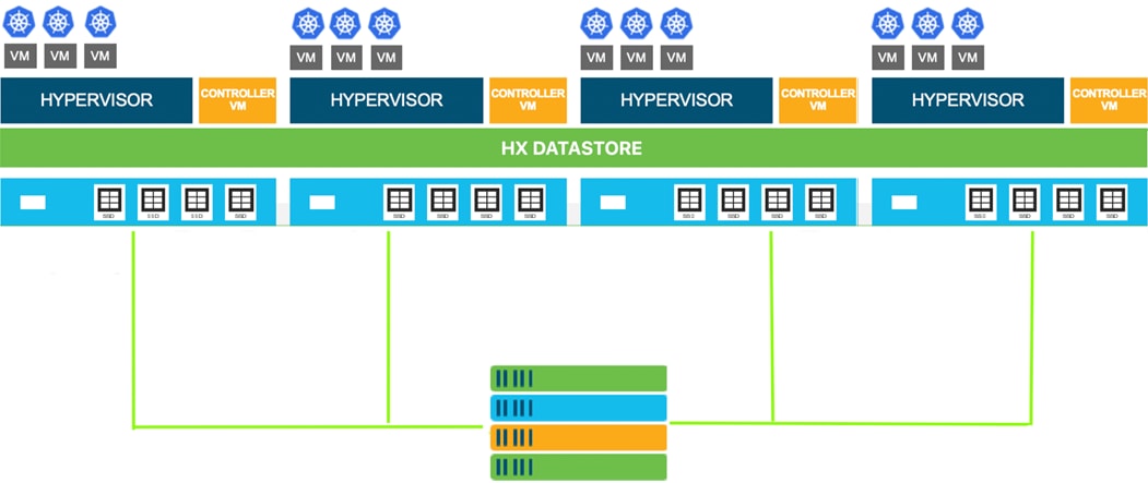
The Cisco HyperFlex system provides a fully contained virtual server platform, with compute and memory resources, integrated networking connectivity, a distributed high-performance log-based filesystem for VM storage, and the hypervisor software for running the virtualized servers, all within a single Cisco UCS management domain. Cisco HyperFlex is compatible with and supports Kubernetes and provides Cisco HyperFlex CSI (HX-CSI) integration for dynamic provisioning of persistent storage to stateful Kubernetes workloads running on HyperFlex platform. The HX-CSI plugin is based on the Kubernetes Container Storage Interface (CSI) specification. Customers can now use the HX-CSI plugin to provision and manage persistent volumes in Kubernetes version 1.13 and later.
Figure 1 Cisco HyperFlex System for Kubernetes Overview
Cisco Unified Computing System
Cisco Unified Computing System (Cisco UCS) is a next-generation data center platform that unites compute, network, and storage access. The platform, optimized for virtual environments, is designed using open industry-standard technologies and aims to reduce total cost of ownership (TCO) and increase business agility. The system integrates a low-latency, lossless 10 Gigabit Ethernet, 25 Gigabit Ethernet or 40 Gigabit Ethernet unified network fabric with enterprise-class, x86-architecture servers. It is an integrated, scalable, multi chassis platform in which all resources participate in a unified management domain.
The main components of Cisco Unified Computing System are:
· Computing: The system is based on an entirely new class of computing system that incorporates rack-mount and blade servers based on Intel Xeon Processors.
· Network: The system is integrated onto a low-latency, lossless, 10Gbps, 25Gbps or 40Gbps unified network fabric, with an option for 100Gbps uplinks. This network foundation consolidates LANs, SANs, and high-performance computing networks which are often separate networks today. The unified fabric lowers costs by reducing the number of network adapters, switches, and cables, and by decreasing the power and cooling requirements.
· Virtualization: The system unleashes the full potential of virtualization by enhancing the scalability, performance, and operational control of virtual environments. Cisco security, policy enforcement, and diagnostic features are now extended into virtualized environments to better support changing business and IT requirements.
· Storage access: The system provides consolidated access to both SAN storage and Network Attached Storage (NAS) over the unified fabric. By unifying storage access, Cisco Unified Computing System can access storage over Ethernet, Fibre Channel, Fibre Channel over Ethernet (FCoE), and iSCSI. This provides customers with their choice of storage protocol and physical architecture, and enhanced investment protection. In addition, the server administrators can pre-assign storage-access policies for system connectivity to storage resources, simplifying storage connectivity, and management for increased productivity.
· Management: The system uniquely integrates all system components which enable the entire solution to be managed as a single entity by Cisco UCS Manager (UCSM). Cisco UCS Manager has an intuitive GUI, a CLI, and a robust API to manage all system configuration and operations. Cisco UCS can also be managed by Cisco Intersight, a cloud-based management and monitoring platform which offers a single pane of glass portal for multiple Cisco UCS systems across multiple locations.
Cisco Unified Computing System is designed to deliver:
· A reduced Total Cost of Ownership and increased business agility.
· Increased IT staff productivity through just-in-time provisioning and mobility support.
· A cohesive, integrated system which unifies the technology in the data center. The system is managed, serviced and tested as a whole.
· Scalability through a design for hundreds of discrete servers and thousands of virtual machines and the capability to scale I/O bandwidth to match demand.
· Industry standards supported by a partner ecosystem of industry leaders.
Cisco UCS Fabric Interconnect
Cisco UCS Fabric Interconnect (FI) is a core part of Cisco Unified Computing System, providing both network connectivity and management capabilities for the system. Depending on the model chosen, Cisco UCS Fabric Interconnect offers line-rate, low-latency, lossless Ethernet, Fibre Channel over Ethernet (FCoE) and Fibre Channel connectivity. Cisco UCS Fabric Interconnects provide the management and communication backbone for the Cisco UCS C-Series, S-Series and HX-Series Rack-Mount Servers, Cisco UCS B-Series Blade Servers and Cisco UCS 5100 Series Blade Server Chassis. All servers and chassis, and therefore all blades, attached to the Cisco UCS Fabric Interconnects become part of a single, highly available management domain. In addition, by supporting unified fabrics, Cisco UCS Fabric Interconnects provide both the LAN and SAN connectivity for all servers within its domain. The product family supports Cisco low-latency, lossless Ethernet unified network fabric capabilities, which increase the reliability, efficiency, and scalability of Ethernet networks. The Fabric Interconnect supports multiple traffic classes over the Ethernet fabric from the servers to the uplinks. Significant TCO savings come from an FCoE-optimized server design in which network interface cards (NICs), host bus adapters (HBAs), cables, and switches can be consolidated.
Cisco UCS 6332-16UP Fabric Interconnect
Cisco UCS 6332-16UP Fabric Interconnect is a one-rack-unit (1RU) 10/40 Gigabit Ethernet, FCoE, and native Fibre Channel switch offering up to 2430 Gbps of throughput. The switch has 24 40Gbps fixed Ethernet and FCoE ports, plus 16 1/10Gbps fixed Ethernet, FCoE, or 4/8/16 Gbps FC ports. Up to 18 of the 40Gbps ports can be reconfigured as 4x10Gbps breakout ports, providing up to 88 total 10Gbps ports, although Cisco HyperFlex nodes must use a 40GbE VIC adapter in order to connect to a Cisco UCS 6300 Series Fabric Interconnect.
Figure 2 Cisco UCS 6332-16UP Fabric Interconnect

![]() When used for a Cisco HyperFlex deployment, due to mandatory QoS settings in the configuration, the 6332 and 6332-16UP will be limited to a maximum of four 4x10Gbps breakout ports, which can be used for other non-HyperFlex servers.
When used for a Cisco HyperFlex deployment, due to mandatory QoS settings in the configuration, the 6332 and 6332-16UP will be limited to a maximum of four 4x10Gbps breakout ports, which can be used for other non-HyperFlex servers.
Cisco HyperFlex HX-Series Nodes
A standard HyperFlex cluster requires a minimum of three HX-Series “converged” nodes (that is, nodes with shared disk storage). Data is replicated across at least two of these nodes, and a third node is required for continuous operation in the event of a single-node failure. Each node that has disk storage is equipped with at least one high-performance SSD drive for data caching and rapid acknowledgment of write requests. Each node also is equipped with additional disks, up to the platform’s physical limit, for long term storage and capacity.
Cisco HyperFlex HXAF240c-M5SX All-Flash Node
This capacity optimized Cisco HyperFlex all-flash model contains a 240 GB M.2 form factor solid-state disk (SSD) that acts as the boot drive, a 240 GB housekeeping SSD drive, either a single 375 GB Optane NVMe SSD, a 1.6 TB NVMe SSD or 1.6 TB SAS SSD write-log drive installed in a rear hot swappable slot, and six to twenty-three 960 GB or 3.8 TB SATA SSD drives for storage capacity. Optionally, the Cisco HyperFlex Acceleration Engine card can be added to improve write performance and compression. For configurations requiring self-encrypting drives, the caching SSD is replaced with an 800 GB SAS SED SSD, and the capacity disks are also replaced with 960 GB or 3.8 TB SED SSDs.
Figure 3 HXAF240c-M5SX Node

![]() In HX-series all-flash nodes either a 375 GB Optane NVMe SSD, a 1.6 TB SAS SSD or 1.6 TB NVMe SSD caching drive may be chosen. While the Optane and NVMe options can provide a higher level of performance, the partitioning of the three disk options is the same, therefore the amount of cache available on the system is the same regardless of the model chosen. Caching amounts are not factored in as part of the overall cluster capacity, only the capacity disks contribute to total cluster capacity.
In HX-series all-flash nodes either a 375 GB Optane NVMe SSD, a 1.6 TB SAS SSD or 1.6 TB NVMe SSD caching drive may be chosen. While the Optane and NVMe options can provide a higher level of performance, the partitioning of the three disk options is the same, therefore the amount of cache available on the system is the same regardless of the model chosen. Caching amounts are not factored in as part of the overall cluster capacity, only the capacity disks contribute to total cluster capacity.
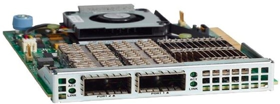
Cisco VIC 1387 MLOM Interface Cards
Cisco UCS VIC 1387 Card is a dual-port Enhanced Quad Small Form-Factor Pluggable (QSFP+) 40Gbps Ethernet and Fibre Channel over Ethernet (FCoE)-capable PCI Express (PCIe) modular LAN-on-motherboard (mLOM) adapter installed in the Cisco UCS HX-Series Rack Servers. Cisco UCS VIC 1387 is used in conjunction with the Cisco UCS 6332 or 6332-16UP model Fabric Interconnects.
The mLOM is used to install a Cisco VIC without consuming a PCIe slot, which provides greater I/O expandability. It incorporates next-generation converged network adapter (CNA) technology from Cisco, providing investment protection for future feature releases. The card enables a policy-based, stateless, agile server infrastructure that can present up to 256 PCIe standards-compliant interfaces to the host, each dynamically configured as either a network interface card (NICs) or host bus adapter (HBA). The personality of the interfaces is set programmatically using the service profile associated with the server. The number, type (NIC or HBA), identity (MAC address and World Wide Name [WWN]), failover policy, adapter settings, bandwidth, and quality-of-service (QoS) policies of the PCIe interfaces are all specified using the service profile.
Figure 4 Cisco VIC 1387 mLOM Card
![]() Hardware revision V03 or later of the Cisco VIC 1387 card is required for the Cisco HyperFlex HX-series servers.
Hardware revision V03 or later of the Cisco VIC 1387 card is required for the Cisco HyperFlex HX-series servers.
Cisco HyperFlex Data Platform Software
The Cisco HyperFlex HX Data Platform is a purpose-built, high-performance, distributed file system with a wide array of enterprise-class data management services. The data platform’s innovations redefine distributed storage technology, exceeding the boundaries of first-generation hyperconverged infrastructures. The data platform has all the features expected in an enterprise shared storage system, eliminating the need to configure and maintain complex Fibre Channel storage networks and devices. The platform simplifies operations and helps ensure data availability. Enterprise-class storage features include the following:
· Data protection creates multiple copies of the data across the cluster so that data availability is not affected if single or multiple components fail (depending on the replication factor configured).
· Stretched clusters allow nodes to be evenly split between two physical locations, keeping a duplicate copy of all data in both locations, thereby providing protection in case of an entire site failure.
· Logical availability zones provide multiple logical grouping of nodes and distributes the data across these groups in such a way that no single group has more than one copy of the data. This enables enhanced protection from node failures, allowing for more nodes to fail while the overall cluster remains online.
· Deduplication is always on, helping reduce storage requirements in virtualization clusters in which multiple operating system instances in guest virtual machines result in large amounts of replicated data.
· Compression further reduces storage requirements, reducing costs, and the log-structured file system is designed to store variable-sized blocks, reducing internal fragmentation.
· Replication copies virtual machine level snapshots from one Cisco HyperFlex cluster to another, to facilitate recovery from a cluster or site failure, via a failover to the secondary site of all VMs.
· Encryption stores all data on the caching and capacity disks in an encrypted format, to prevent accidental data loss or data theft. Key management can be done using local Cisco UCS Manager managed keys, or third-party Key Management Systems (KMS) via the Key Management Interoperability Protocol (KMIP).
· Thin provisioning allows large volumes to be created without requiring storage to support them until the need arises, simplifying data volume growth and making storage a “pay as you grow” proposition.
· Fast, space-efficient clones rapidly duplicate virtual storage volumes so that virtual machines can be cloned simply through metadata operations, with actual data copied only for write operations.
· Snapshots help facilitate backup and remote-replication operations, which are needed in enterprises that require always-on data availability.
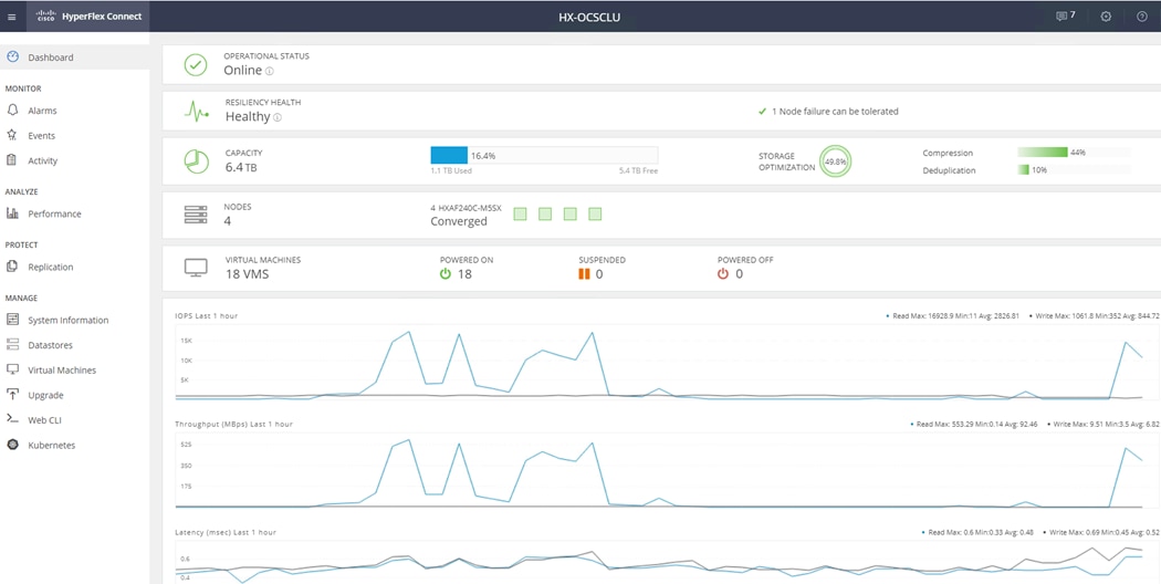
Cisco HyperFlex Connect HTML5 Management Web Page
An HTML 5 based Web UI named HyperFlex Connect is available for use as the primary management tool for Cisco HyperFlex. Through this centralized point of control for the cluster, administrators can create volumes, monitor the data platform health, and manage resource use. Administrators can also use this data to predict when the cluster will need to be scaled. To use the HyperFlex Connect UI, connect using a web browser to the HyperFlex cluster IP address: http://<hx controller cluster ip>.
Figure 5 HyperFlex Connect UI
Cisco HyperFlex HX Data Platform Administration Plug-in
The Cisco HyperFlex HX Data Platform is also administered secondarily through a VMware vSphere web client plug-in, which is deployed automatically by the Cisco HyperFlex installer.
Cisco HyperFlex HX Data Platform Controller
A Cisco HyperFlex HX Data Platform controller resides on each node and implements the distributed file system. The controller runs as software in user space within a virtual machine, and intercepts and handles all I/O from the guest virtual machines. The Storage Controller Virtual Machine (SCVM) uses the VMDirectPath I/O feature to provide direct PCI passthrough control of the physical server’s SAS disk controller, or direct control of the PCI attached NVMe based SSDs. This method gives the controller VM full control of the physical disk resources, utilizing the SSD drives as a read/write caching layer, and the HDDs or SDDs as a capacity layer for distributed storage. The controller integrates the data platform into the VMware vSphere cluster through the use of three preinstalled VMware ESXi vSphere Installation Bundles (VIBs) on each node:
· IO Visor: This VIB provides a network file system (NFS) mount point so that the ESXi hypervisor can access the virtual disks that are attached to individual virtual machines. From the hypervisor’s perspective, it is simply attached to a network file system. The IO Visor intercepts guest VM IO traffic, and intelligently redirects it to the HyperFlex SCVMs.
· VMware API for Array Integration (VAAI): This storage offload API allows vSphere to request advanced file system operations such as snapshots and cloning. The controller implements these operations via manipulation of the filesystem metadata rather than actual data copying, providing rapid response, and thus rapid deployment of new environments.
· stHypervisorSvc: This VIB adds enhancements and features needed for HyperFlex data protection and VM replication.
Data Operations and Distribution
The Cisco HyperFlex HX Data Platform controllers handle all read and write operation requests from the guest VMs to their virtual disks (VMDK) stored in the distributed datastores in the cluster. The data platform distributes the data across multiple nodes of the cluster, and also across multiple capacity disks of each node, according to the replication level policy selected during the cluster setup. This method avoids storage hotspots on specific nodes, and on specific disks of the nodes, and thereby also avoids networking hotspots or congestion from accessing more data on some nodes versus others.
Replication Factor
The policy for the number of duplicate copies of each storage block is chosen during cluster setup and is referred to as the replication factor (RF).
· Replication Factor 3: For every I/O write committed to the storage layer, 2 additional copies of the blocks written will be created and stored in separate locations, for a total of 3 copies of the blocks. Blocks are distributed in such a way as to ensure multiple copies of the blocks are not stored on the same disks, nor on the same nodes of the cluster. This setting can tolerate simultaneous failures of 2 entire nodes in a cluster of 5 nodes or greater, without losing data and resorting to restore from backup or other recovery processes. RF3 is recommended for all production systems.
· Replication Factor 2: For every I/O write committed to the storage layer, 1 additional copy of the blocks written will be created and stored in separate locations, for a total of 2 copies of the blocks. Blocks are distributed in such a way as to ensure multiple copies of the blocks are not stored on the same disks, nor on the same nodes of the cluster. This setting can tolerate a failure of 1 entire node without losing data and resorting to restore from backup or other recovery processes. RF2 is suitable for non-production systems, or environments where the extra data protection is not needed. HyperFlex stretched clusters use the RF2 setting, however there are 2 copies of the data kept in both halves of the cluster, so effectively there are four copies stored.
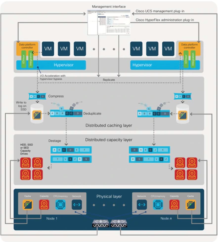
Data Write and Compression Operations
Internally, the contents of each virtual disk are subdivided and spread across multiple servers by the HXDP software. For each write operation, the data is intercepted by the IO Visor module on the node where the VM is running, a primary node is determined for that particular operation via a hashing algorithm, and then sent to the primary node via the network. The primary node compresses the data in real time, writes the compressed data to the write log on its caching SSD, and replica copies of that compressed data are sent via the network and written to the write log on the caching SSD of the remote nodes in the cluster, according to the replication factor setting. For example, at RF=3 a write operation will be written to write log of the primary node for that virtual disk address, and two additional writes will be committed in parallel on two other nodes. Because the virtual disk contents have been divided and spread out via the hashing algorithm for each unique operation, this method results in all writes being spread across all nodes, avoiding the problems with data locality and “noisy” VMs consuming all the IO capacity of a single node. The write operation will not be acknowledged until all three copies are written to the caching layer SSDs. Written data is also cached in a write log area resident in memory in the controller VM, along with the write log on the caching SSDs. This process speeds up read requests when reads are requested of data that has recently been written.
Data Destaging and Deduplication
The Cisco HyperFlex HX Data Platform constructs multiple write log caching segments on the caching SSDs of each node in the distributed cluster. As write cache segments become full and based on policies accounting for I/O load and access patterns, those write cache segments are locked and new writes roll over to a new write cache segment. The data in the now locked cache segment is destaged to the HDD capacity layer of the nodes for the Hybrid system or to the SSD capacity layer of the nodes for the All-Flash or All-NVMe systems. During the destaging process, data is deduplicated before being written to the capacity storage layer, and the resulting data can now be written to the HDDs or SDDs of the server. On hybrid systems, the now deduplicated and compressed data is also written to the dedicated read cache area of the caching SSD, which speeds up read requests of data that has recently been written. When the data is destaged to the capacity disks, it is written in a single sequential operation, avoiding disk head seek thrashing on the spinning disks and accomplishing the task in the minimal amount of time. Since the data is already deduplicated and compressed before being written, the platform avoids additional I/O overhead often seen on competing systems, which must later do a read/dedupe/compress/write cycle. Deduplication, compression and destaging take place with no delays or I/O penalties to the guest VMs making requests to read or write data, which benefits both the HDD and SDD configurations.
Figure 6 HyperFlex HX Data Platform Data Movement
Data Read Operations
For data read operations, data may be read from multiple locations. For data that was very recently written, the data is likely to still exist in the write log of the local platform controller memory, or the write log of the local caching layer disk. If local write logs do not contain the data, the distributed filesystem metadata will be queried to see if the data is cached elsewhere, either in write logs of remote nodes, or in the dedicated read cache area of the local and remote caching SSDs of hybrid nodes. Finally, if the data has not been accessed in a significant amount of time, the filesystem will retrieve the requested data from the distributed capacity layer. As requests for reads are made to the distributed filesystem and the data is retrieved from the capacity layer, the caching SSDs of hybrid nodes populate their dedicated read cache area to speed up subsequent requests for the same data. This multi-tiered distributed system with several layers of caching techniques, ensures that data is served at the highest possible speed, leveraging the caching SSDs of the nodes fully and equally. All-flash and all-NVMe configurations do not employ a dedicated read cache, because such caching does not provide any performance benefit since the persistent data copy already resides on high-performance SSDs.
In summary, the Cisco HyperFlex HX Data Platform implements a distributed, log-structured file system that performs data operations via two configurations:
· In a Hybrid configuration, the data platform provides a caching layer using SSDs to accelerate read requests and write responses, and it implements a storage capacity layer using HDDs.
· In an All-Flash or all-NVMe configuration, the data platform provides a dedicated caching layer using high endurance SSDs to accelerate write responses, and it implements a storage capacity layer also using SSDs. Read requests are fulfilled directly from the capacity SSDs, as a dedicated read cache is not needed to accelerate read operations.
Cisco HyperFlex CSI Storage Plugin
Container Storage Integration (CSI) is a standard for exposing arbitrary block and file storage systems to containerized workloads on Kubernetes. Using CSI standard interface, third-party storage providers can write and deploy plugins exposing their storage systems in Kubernetes. HX-CSI is Cisco’s storage plugin implementation for containerized workloads that consumes the CSI framework.
Cisco HyperFlex Container Storage Interface (CSI) is an out-of-tree container-based Kubernetes storage integration; which is deployed and consumed through standard Kubernetes primitives such as Persistent Volume Claims and Storage Classes. Cisco HyperFlex CSI supports the following features:
· Dynamic creation and deletion of volumes
· Dynamic volume attach and detach
The Cisco HyperFlex CSI plugin is deployed as containers on Anthos cluster. Figure 7 shows the different components of the Cisco HyperFlex CSI deployment and how they interact with each other.
Figure 7 Cisco HX-CSI Storage Plugin
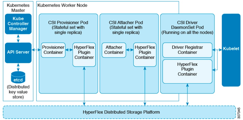
The following are the pods that get deployed as part of HX-CSI:
· csi-attacher-hxcsi
- Type - StatefulSet
- Number of Instances - One per Kubernetes Cluster
- Purpose - Required by CSI, but not currently in used in the Cisco deployment.
· csi-provisioner-hxcsi
- Type - StatefulSet
- Number of Instances - One per Kubernetes Cluster
- Purpose - Watches Kubernetes Persistent Volume Claim objects and triggers CreateVolume and DeleteVolume operations as part of CSI spec.
· csi-nodeplugin-hxcsi
- Type - DaemonSet
- Number of Instances - One per Kubernetes Worker Node
- Purpose - Discovery and formatting of provisioned HyperFlex iSCSI LUNs on Kubernetes worker nodes. Implements NodeStage/NodeUnstage and NodePublish/NodeUnpublish Volume APIs as part of Kubernetes CSI spec.
Cisco Nexus Switch
The Cisco Nexus 93180YC-EX-24 Switch is a 1RU switch with latency of less than 1 microsecond. The 24 downlink ports (licensed to use any 24 ports out of the 48 ports) on the 93180YC-EX-24 can be configured to work as 1, 10, or 25Gbps ports, offering deployment flexibility and investment protection. The 6 uplink ports can support 40 and 100Gbps or a combination of 1, 10, 25, 40, 50, and 100Gbps connectivity, thus offering flexible migration options. The switch has FC-FEC enabled for 25Gbps and supports up to 3m in DAC connectivity.
Figure 8 Cisco Nexus 93180YC-EX Switch
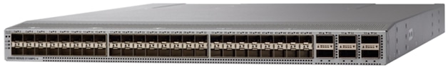
![]() Any upstream switch in Cisco’s Nexus portfolio can be used for this solution. There is no dependency or recommendation to use the above mentioned switch.
Any upstream switch in Cisco’s Nexus portfolio can be used for this solution. There is no dependency or recommendation to use the above mentioned switch.
Cisco AppDynamics
AppDynamics is designed for production and pre-production environments, AppDynamics gives user visibility into their entire application topology in a single pane of glass. AppDynamics provides real-time monitoring, business insights, anomaly detection, and full visibility for the entire application landscape-so that the customers can spend less time fixing issues and more time driving in innovation and delivery for exceptional customer experience. For more information on AppDynamics, see: https://www.appdynamics.com/.
AppDynamics Provides the following capabilities:
· Application Performance Monitoring
Application Performance Management (APM) solution monitor apps for users and give them the power to ensure flawless customer experiences. Complex distributed applications demand end-to-end management. Our APM solution delivers application mapping, dynamic baselining and code-level diagnostics.
Figure 9 AppDynamics APM
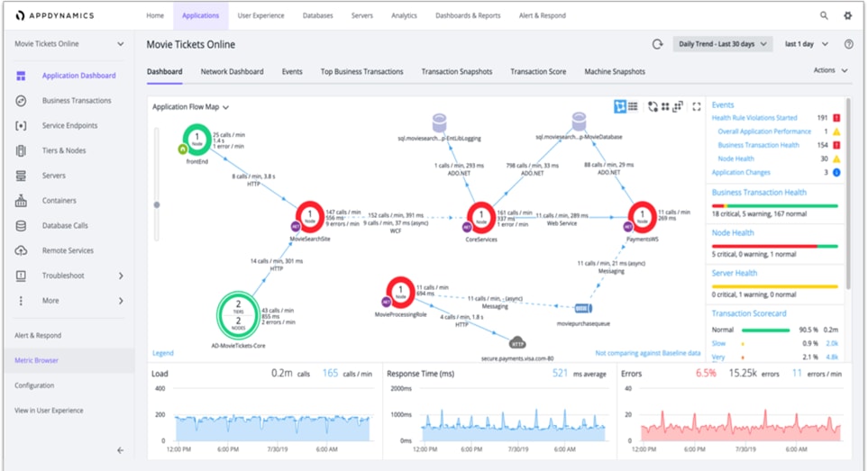
Figure 10 AppDynamics Baselining and Anomaly Detection
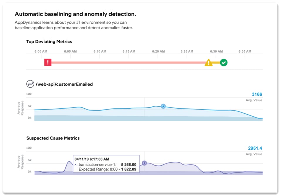
Figure 11 AppDynamics Root Cause Analysis
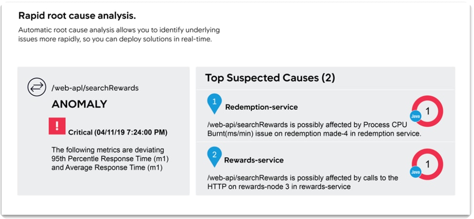
Figure 12 Root Cause Analysis at Code Level
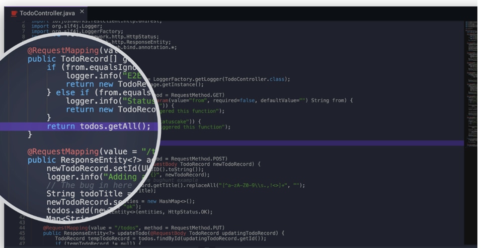
For more information on APM, see: https://www.appdynamics.com/product/application-performance-management
Business Performance Monitoring
Business IQ is an industry first that translates code-level monitoring into immediate, clear and actionable insights, by correlating application performance, user experience and business outcomes. From the end user’s front-end to the application back-end, AppDynamics is the only platform that unifies full stack performance monitoring for business and IT departments.
Figure 13 AppDynamics Business Performance Monitoring
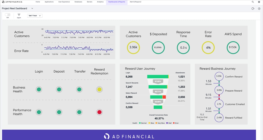
For more information on Business Performance Monitoring, see: https://www.appdynamics.com/product/business-iq
End User Monitoring
Create better customer experiences and quickly solve issues by automatically capturing errors, crashes, network requests, page load details, and other metrics. Also, End User Monitoring gives users a clear understanding of how third-party APIs and content services are impacting performance, giving users more leverage to enforce SLAs.
Figure 14 AppDynamics End User Monitoring
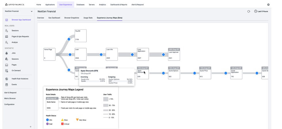
For more details on End User Monitoring, see: https://www.appdynamics.com/product/end-user-monitoring
AIOps
Together with Cisco, AppDynamics provides our vision for AIOps: the Central Nervous System for IT. The Central Nervous System is a platform that delivers deep, cross-domain visibility and insights with the ability to auto-mate actions, reduce the amount of time-consuming IT tasks, and enable teams to drive innovation. With the Central Nervous System for IT, AppDynamics and Cisco empower businesses with AI powered insights and automation that help them take the right action, at exactly the right time.
Figure 15 AppDynamics Central Nervous System
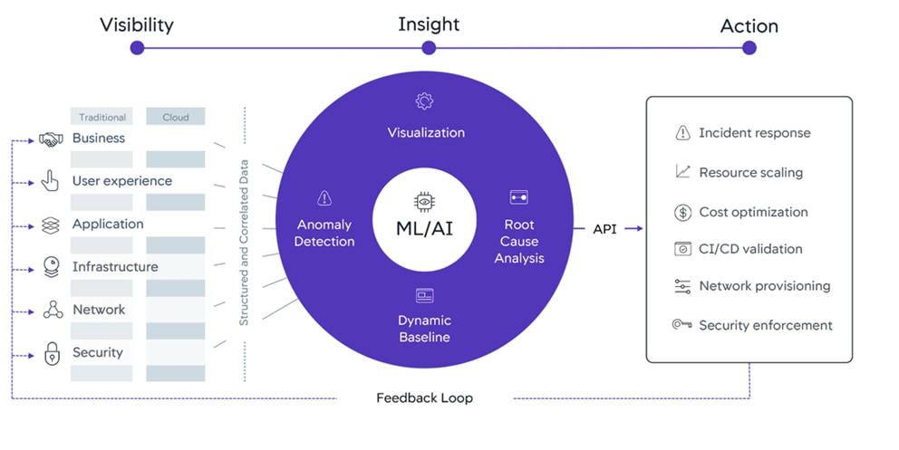
For information on Central Nervous System, see: https://www.appdynamics.com/central-nervous-system
Cloud
Whether it's a new cloud application or a user is migrating an existing application, we provide all the cloud monitoring tools that users need to accelerate their journey to the cloud.
For information on Cloud Monitoring, see: https://www.appdynamics.com/solutions/cloud/cloud-monitoring
AppDynamics support various cloud platforms and cloud native programming, which includes:
· Public Cloud like AWS, GCP and Azure
· Serverless Functions
· Docker Monitoring
· Kubernetes Monitoring
Infrastructure Visibility
This makes sure that the application performance is fully supported by the infrastructure with server, database and network performance visibility at the user’s end. Infrastructure Visibility lets users drill down into their business transactions to see and troubleshoot server, database and network issues before they affect customers—and do it within minutes.
Figure 16 AppDynamics Infrastructure Visibility
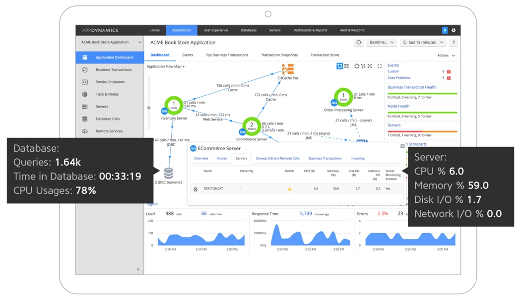
For information on Infrastructure Visibility, see: https://www.appdynamics.com/product/application-performance-management/infrastructure-visibility
Google Cloud’s Anthos
Anthos is a platform composed of multiple products and capabilities designed to help organizations modernize their applications and run them on hybrid and multi-cloud environments. Anthos GKE on-prem is a Google provided Kubernetes experience designed to run within the data center and be part of a hybrid cloud architecture that enables organizations to construct and manage modern hybrid-cloud applications. GKE on-prem, a solution built on open-source technologies, runs on-premises in a VMware vSphere-based infrastructure, and can be managed from a single control point along with Anthos GKE in Google Cloud and in other clouds. Adopting containers, microservices, service mesh, and other transformational technologies enables organizations to experience consistent application development cycles and production-ready workloads in local and cloud-based environments. Figure 17 depicts the Anthos overview showing the connectivity between cloud and on-premises.
For more information about Anthos, see: https://cloud.google.com/anthos/. Anthos is a platform that offers a collection of products and capabilities:
· Anthos Config Management - Automates the policy and security of hybrid Kubernetes deployments.
· Anthos Service Mesh - Enhances application observability (trace path), security, and control with an Istio-powered service mesh.
· Google Cloud Marketplace for Kubernetes Applications - A catalog of curated container applications available for easy deployment.
· Migrate for Anthos - Automatic migration of physical services and VMs from on-premises to the cloud.
· Stackdriver - Management service offered by Google for logging and monitoring cloud instances.
· Anthos GKE deployed on-prem - is hybrid cloud software that brings Google Kubernetes Engine (GKE) to on-premises data centers
Figure 17 Google Cloud’s Anthos overview
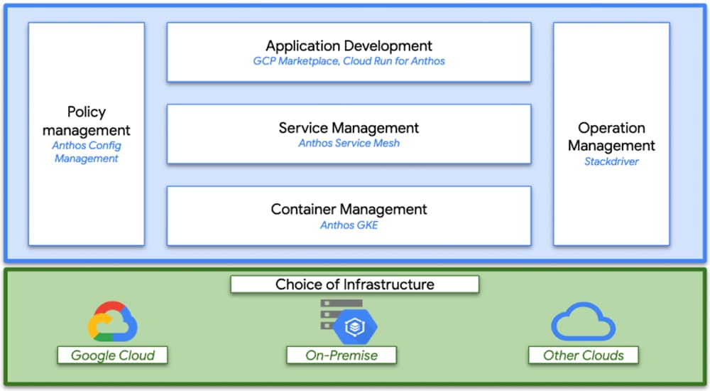
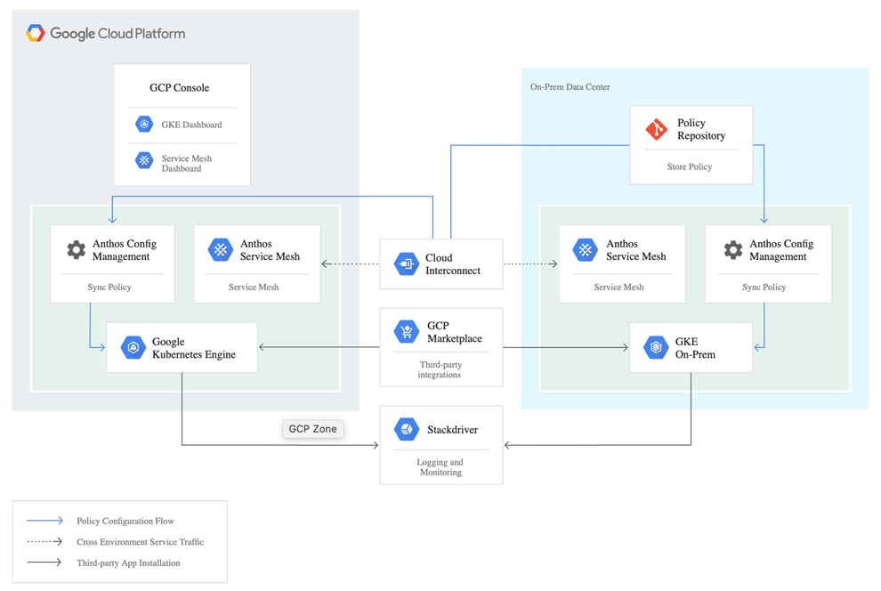
Figure 18 Interconnection of Anthos GKE on-prem with GCP
Kubernetes Orchestration
Enterprises have embraced container technology for application-specific workload requirements to adopt themselves to ever-changing IT needs. Containers by design require less overhead to deploy and all that is needed is the packaging of application code and supporting libraries together, because all other services depend on the host OS. Rather than managing a complete virtual machine (VM) environment, developers can instead focus on the application development process. As container technology began to find appeal in the enterprise landscape, enterprises had a need for both fault tolerance and application scaling. In response, Google partnered with the Linux Foundation to form the Cloud Native Computing Foundation (CNCF). Together, they introduced Kubernetes (K8s), an open-source platform for orchestrating and managing containers.
Anthos GKE
Anthos GKE is a certified distribution of Kubernetes in the Google Cloud. It allows end users to easily deploy managed, production-ready Kubernetes clusters, enabling developers to focus primarily on application development rather than on the management of their environment. Deploying Kubernetes clusters in Anthos GKE offers the following benefits:
· Simplified application deployment - Anthos GKE allows for rapid development, and also provides updates of applications and services. By providing simple descriptions of the expected system resources (compute, memory, and storage) required by the application containers, the Kubernetes Engine automatically provisions and manages the lifecycle of the cluster environment.
· Monitoring – GCP (Google Cloud Platform) provides a single pane of glass for managing clusters and workloads. Anthos GKE clusters are continually monitored by Google Site Reliability Engineers (SREs) to make sure that clusters behave as expected by collecting regular metrics and observing the use of assigned system resources. Dashboard provides visibility into cluster health to make sure the deployed applications are highly available and there is no single point of failure.
· Securing Clusters in Google Cloud - An end user can ensure that clusters are secure and accessible by customizing network policies available from Google Cloud’s Global Virtual Private Cloud. Public services can be placed behind a single global IP address for load balancing purposes. A single IP can help provide high availability for applications and protect against Distributed Denial of Service (DDOS) and other forms of attacks that might hinder service performance.
· Easily Scaling – An end user can enable auto-scaling on their cluster to easily counter both planned and unexpected increases in application demands. Auto-scaling helps make sure that system resources are always available by increasing capacity during high-demand windows. It also allows the cluster to return to its previous state and size after peak demand subsides.
Anthos GKE Deployed on-prem
Anthos GKE deployed on-prem (GKE on-prem) is an extension of Google Kubernetes Engine that is deployed in an end user’s private data center. An organization can deploy the same container applications designed to run in Google Cloud and in Kubernetes clusters on premises. GKE on-prem offers the following benefits:
· Cost - End users can realize significant cost savings by utilizing their own physical resources for their application deployments instead of provisioning resources in their Google Cloud environment.
· Develop and publish - On-premises deployments can be used while applications are in development, which allows for testing of applications in the privacy of a local data center before being made publicly available in the cloud.
· Security – Customers with increased security concerns or sensitive data sets that they do not want to store in the public cloud can be run securely in their own data centers fulfilling their organizational requirements.
Anthos Config Management
Anthos Config Management is a key component of Anthos. With Anthos Config Management, users can create a common configuration across all their infrastructure, including custom policies, and apply it both on-premises and in the cloud. Anthos Config Management evaluates changes and rolls them out to all Kubernetes clusters so that the user’s desired state is always reflected. Anthos Config Management allows cluster operators to manage single clusters, multi-tenant clusters, and multi-cluster Kubernetes deployments by using files, called configs, stored in a Git repository. Some configs are Kubernetes object manifests. Other configs are not object manifests, but instead provide information needed by Anthos Config Management. Users can write configs in YAML or JSON. Anthos Config Management watches for updates to these files and applies changes to all relevant clusters automatically. A configuration-as-code approach allows users to manage the configuration of Google Kubernetes Engine (GKE) or Anthos GKE deployed on-prem clusters by using the same principles that users may already be using to manage their applications deployed in Kubernetes. With Anthos Config Management, users need do the following:
· Code reviews are required to be done before changes are pushed to the live environment, and audit exactly which commit caused a configuration change.
· Reduce the risk of shadow ops, where unvetted changes are pushed to live clusters, and where it is difficult to understand the differences between a documented configuration and users’ live environment. Users can require that all cluster configuration changes are propagated by using Anthos Config Management and lock down direct access to the Kubernetes API.
· Apply configuration changes to hundreds of clusters with a single Git commit instead of writing scripts to run thousands of kubectl apply commands manually.
· Ensure that a change is pushed to each relevant cluster and only relevant clusters, based on metadata applied to each cluster.
· Use Continuous Integration/Continuous Deployment (CI/CD) pipelines to test users changes and apply them automatically when tests pass.
· Use a revert then investigate strategy to roll back breaking changes and get users’ live clusters back into a good working state before fixing the problematic change and applying it as a new commit. This strategy reduces downtime due to configuration-related outages. Anthos Config Management synchronizes the states of user’s clusters with their Git repository. The Config Management Operator custom controller monitors the user’s Git repository and the states of user clusters, keeping them consistent for each Kubernetes object that has been chosen. If Operator fails to apply changes to a resource, the resource is left in the last known good state. Anthos Config Management can configure a single cluster or multiple clusters from a single Git repository.
Continuous Integration / Continuous Delivery with Anthos
Digital transformation in the enterprise extends beyond just technology into the organizational and process changes. CI/CD is part of the larger transition to a DevOps mentality that is occurring in the enterprise. Anthos is designed to support CI/CD and DevOps processes and tools by providing integrations into Google Cloud services or allowing operations teams to plug into their existing workflows. Anthos is built to work with Google Cloud CI/CD supporting tools, such as: Cloud Build, Google Container Registry and Source Repositories to provide a foundation out of the box to integrate seamlessly with Google Cloud. However, Anthos also fully supports third-party CI/CD tools for builds, pipelines, deployments and more to ensure that Anthos customers have the flexibility and choice to meet their application needs. For a sample CI/CD model deployment with Anthos, see: https://cloud.google.com/solutions/partners/a-hybrid-cloud-native-devsecops-pipeline-with-jfrog-artifactory-and-gke-on-prem
Google Cloud Marketplace for Kubernetes Apps
Kubernetes applications are enterprise-ready containerized solutions with prebuilt deployment templates, featuring portability, simplified licensing, and consolidated billing. They can be run on Anthos, in the cloud, on-premises, or on Kubernetes clusters hosted in other environments. These are not just container images, but open-source, Google-built, and commercial applications that increase developer productivity, available now on GCP Marketplace. The Kubernetes apps in Google Cloud Marketplace include container images and configuration files, such as a kubectl configuration or a Helm chart. When users deploy an app from Google Cloud Marketplace, the Kubernetes resources are created in their cluster, and they can manage the resources as a group. Deploying a Kubernetes app from the Google Cloud Marketplace is as easy as discovering the application from within the marketplace, selecting the cluster (in the cloud or on-prem users wish to deploy to, selecting or creating the desired namespace, setting the application specific options, and clicking deploy). From there, Marketplace will push the application according to the application provider’s specifications and can monitor the progress of the deployment from the Google Cloud Console. The Google Cloud Marketplace integrates billing with the apps that are deployed. Usage metering follows the application no matter where it is deployed or to which environment it is moved. Billing takes place only through GCP and is consolidated with the rest of the user’s spend, resulting in just one bill. Lastly, users pay only for what they use via the transparent consumption-based billing model. See the published solutions with simple click to deploy to Google Kubernetes Engine, and the flexibility to deploy to Kubernetes clusters on-premises or in third-party clouds at: https://console.cloud.google.com/marketplace/browse?filter=solution-type%3Ak8s.
Cloud Run for Anthos
As an Anthos integration, Google Cloud’s app modernization platform, Cloud Run provides custom machine types, VPC networking, and integration with existing Kubernetes‐based solutions. Cloud Run for Anthos provides a flexible serverless development platform on Google Kubernetes Engine (GKE). Cloud Run for Anthos is powered by Knative, an open source project that supports serverless workloads on Kubernetes. Cloud Run is also available as a fully managed serverless platform, without Kubernetes. Cloud Run is a fully managed compute platform that automatically scales the stateless containers. Cloud Run is serverless: it abstracts away all infrastructure management, so that users can focus on what matters most—building great applications. Run containers on Anthos, which supports both Google Cloud and on‐premises environments. Cloud Run is built upon an open standard, Knative, enabling the portability of applications deployed in the user environment.
· Write code the way the user wants, using their favorite languages (Go, Python, Java, C#, PHP, Ruby, Node.js, Shell, and others)
· Abstract away all infrastructure management for a simple developer experience
· Only pay when the user is running the code
Requirements
The following sections detail the physical hardware, software revisions, and firmware versions required to install a single cluster of the Cisco HyperFlex system. Maximum cluster size of 64 nodes can be obtained by combining 32 converged nodes and 32 compute-only nodes.
Physical Components
Table 1 HyperFlex System Components of this Solution
| Components |
Hardware Used |
| Fabric Interconnect |
A pair of Cisco UCS 6332-16UP Fabric Interconnects |
| Servers |
Four Cisco HyperFlex HXAF240c-M5SX All-Flash rack servers (up to 32 servers is supported) |
For complete server specifications and more information, please refer to the Cisco HyperFlex HX240c M5 Node Spec Sheet.
Table 2 lists the hardware component options for the HX240c-M5SX server model used in this solution.
Table 2 Cisco HyperFlex HX240c M5SX All Flash Node Server Configuration
| Cisco HyperFlex HX240c M5SX All Flash Node options |
Hardware required |
| Processors |
2 Intel Xeon Gold 6240 CPUs with 18 cores each |
| Memory |
12 x 16 GB = 192 GB |
| Disk controllers |
Cisco 12Gbps modular SAS controller |
| Solid-state disks (SSDs) |
1 x 240 GB 6Gbps SATA SSD for housekeeping tasks 6 x 960 GB 6Gbps SATA SSDs for capacity tier 1 x 400 GB SAS SSD for caching tier |
| Network |
1 x Cisco UCS VIC 1387 mLOM 1 x Cisco UCS VIC 1385 PCIe card |
| Boot device |
1 x 240 GB M.2 form-factor 6Gbps SATA SSD |
For additional information on supported hardware components HX240c-M5SX server and other HX models, see: https://www.cisco.com/c/en/us/td/docs/unified_computing/ucs/UCS_CVDs/hx_4_vsi_vmware_esxi.html#_Toc24465141
Software Components
Table 3 provides the software components and its versions used in this solution.
Table 3 Software components and versions
| Component |
Software required |
| VMware hypervisor |
VMware ESXi 6.5.0 U3 13932383 |
| VMware vCenter management server |
VMware vCenter Server 6.5 8307201 |
| Cisco HyperFlex HX Data Platform |
Cisco HyperFlex HX Data Platform 4.0.1b |
| Cisco UCS firmware |
Cisco UCS infrastructure: Cisco UCS C-Series bundle 4.0.4d |
| GKE on-prem Admin Appliance |
gke-on-prem-admin-appliance-vsphere-1.2.2-gke.2.ova |
| GKE bundle |
gke-onprem-vsphere-1.2.2-gke.2-full.tgz |
| F5 load balancer |
F5 BIG-IP VE 13.1.3-0.0.6.ALL-scsi.ova |
| Cisco HyperFlex CSI |
HX-CSI version 1.0 |
| Kubernetes version |
Kubernetes version 1.14 |
![]() Users need to have an Enterprise level GCP account for deploying and managing this solution, for more information, see: https://cloud.google.com/resource-manager/docs/creating-managing-projects#creating_a_project
Users need to have an Enterprise level GCP account for deploying and managing this solution, for more information, see: https://cloud.google.com/resource-manager/docs/creating-managing-projects#creating_a_project
![]() Although this solution has been validated with Anthos 1.2, Cisco HyperFlex is qualified as Anthos Ready Platform for Anthos latest versions. For more information, see: https://cloud.google.com/anthos/gke/docs/on-prem/partner-platforms.
Although this solution has been validated with Anthos 1.2, Cisco HyperFlex is qualified as Anthos Ready Platform for Anthos latest versions. For more information, see: https://cloud.google.com/anthos/gke/docs/on-prem/partner-platforms.
Physical Topology
Topology Overview
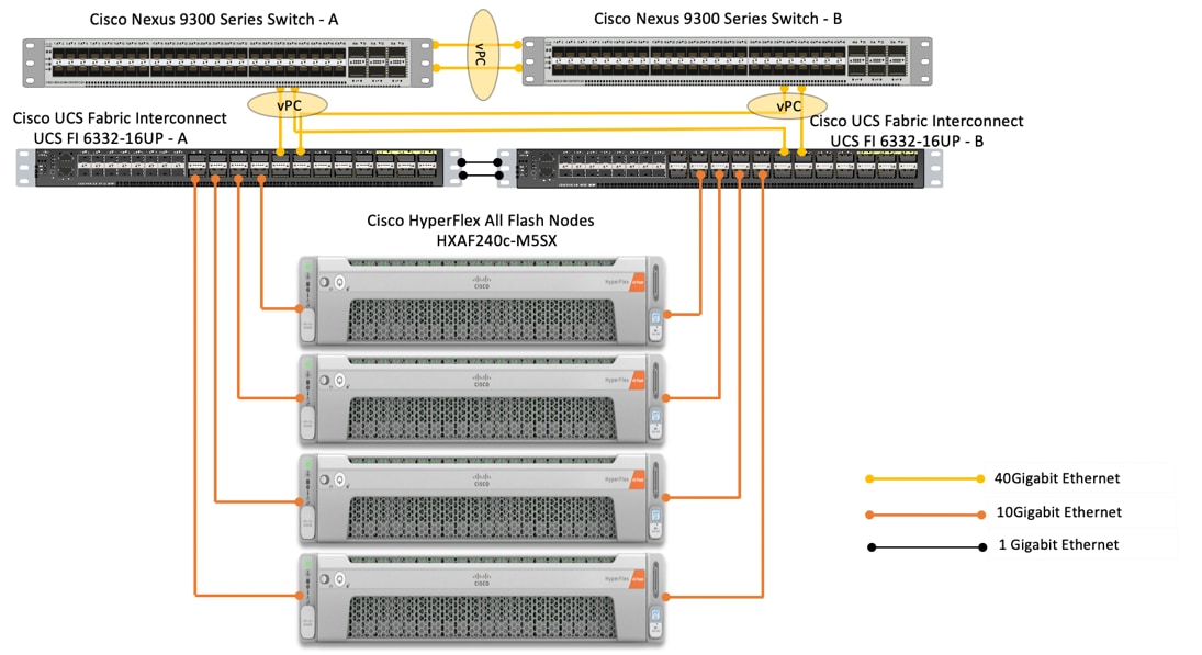
The Cisco HyperFlex system is composed of a pair of Cisco UCS Fabric Interconnects along with up to thirty-two HX-Series rack-mount servers per cluster. Up to thirty-two compute-only servers can also be added per HyperFlex cluster. Adding Cisco UCS rack-mount servers and/or Cisco UCS 5108 Blade chassis, which house Cisco UCS blade servers, allows for additional compute resources in an extended cluster design. The two Fabric Interconnects both connect to every HX-Series rack-mount server, and both connect to every Cisco UCS 5108 blade chassis, and Cisco UCS rack-mount server. Upstream network connections, also referred to as “northbound” network connections are made from the Fabric Interconnects to the customer datacenter network at the time of installation.
Figure 19 depicts the reference architecture proposed for this solution. In our solution we have deployed Google Cloud’s Anthos on a four node Cisco HyperFlex (HX) cluster. Each node in the cluster is Cisco UCS HXAF240c-M5SX All Flash. The HX cluster is connected to a pair of Cisco UCS 6332-16UP Fabric Interconnects. Cisco UCS Manager is a management software that runs on the Fabric Interconnects. Cisco UCS Manager UI is a highly intuitive and provides complete visibility on the infrastructure components. The FIs are connected to the upstream switches; in our solution we used Cisco Nexus 93180YC-EX switches.
Figure 19 Reference Architecture
Infrastructure services such as DNS, NTP and VMWare vCenter are recommended to be installed outside the HyperFlex cluster. Customers can leverage these existing services to deploy and manage the HyperFlex cluster.
The HyperFlex storage solution has several data protection techniques, as explained in detail in the Technology Overview section, one of which is data replication which needs to be configured on HyperFlex cluster creation. Based on the specific performance and data protection requirements, customer can choose either a replication factor of two (RF2) or three (RF3). In this solution we have configured the test HyperFlex cluster with replication factor 3 (RF3).
As described in the Technology Overview section, Cisco HyperFlex distributed file system software runs inside a controller VM, which gets installed on each cluster node. These controller VMs pool and manage all the storage devices and exposes the underlying storage as NFS mount points to the VMware ESXi hypervisors. The ESXi hypervisors exposes these NFS mount points as datastores to the guest virtual machines to store their data.
Logical Topology
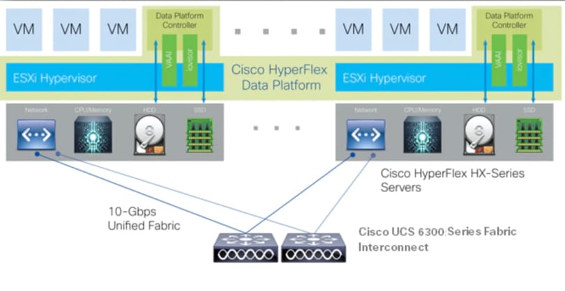
The logical architecture of this solution is designed to support and run Anthos GKE on-prem within a four node Cisco UCS HXAF240c-M5SX All Flash – HyperFlex cluster, which provides physical redundancy for the containerized workloads running on Anthos VMs.
Figure 20 Cisco HyperFlex Logical Architecture
ESXi Host Design
The following sections detail the design of the elements within the VMware ESXi hypervisors, system requirements, virtual networking and the configuration of ESXi for the Cisco HyperFlex HX Distributed Data Platform.
Virtual Networking Design
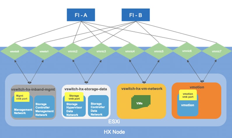
The Cisco HyperFlex system has a pre-defined virtual network design at the ESXi hypervisor level. Four different virtual switches are created by the HyperFlex installer, each using two uplinks, which are each serviced by a vNIC defined in the UCS service profile. The vSwitches created are:
· vswitch-hx-inband-mgmt: This is the default vSwitch0 which is renamed by the ESXi kickstart file as part of the automated installation. The default vmkernel port, vmk0, is configured in the standard Management Network port group. The switch has two uplinks, active on fabric A and standby on fabric B, without jumbo frames. A second port group is created for the Storage Platform Controller VMs to connect to with their individual management interfaces. The VLAN is not a Native VLAN as assigned to the vNIC template, and therefore assigned in ESXi/vSphere
· vswitch-hx-storage-data: This vSwitch is created as part of the automated installation. A vmkernel port, vmk1, is configured in the Storage Hypervisor Data Network port group, which is the interface used for connectivity to the HX Datastores via NFS. The switch has two uplinks, active on fabric B and standby on fabric A, with jumbo frames required. A second port group is created for the Storage Platform Controller VMs to connect to with their individual storage interfaces. The VLAN is not a Native VLAN as assigned to the vNIC template, and therefore assigned in ESXi/vSphere
· vswitch-hx-vm-network: This vSwitch is created as part of the automated installation. The switch has two uplinks, active on both fabrics A and B, and without jumbo frames. The VLAN is not a Native VLAN as assigned to the vNIC template, and therefore assigned in ESXi/vSphere
· vmotion: This vSwitch is created as part of the automated installation. The switch has two uplinks, active on fabric A and standby on fabric B, with jumbo frames required. The VLAN is not a Native VLAN as assigned to the vNIC template, and therefore assigned in ESXi/vSphere
Figure 21 ESXi Network Design
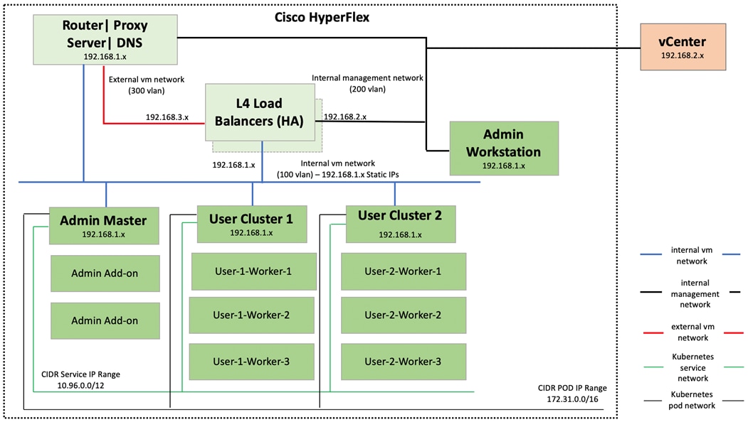
Anthos GKE on-prem Network Topology
Figure 22 shows the network topology diagram for Anthos GKE deployed on-prem on vSphere on Cisco HyperFlex. All the green boxes in the figure represent VMs within the Cisco HyperFlex platform. The boxes represented in a dark green color are created during Anthos GKE on-prem cluster bring-up.
The admin-workstation deployment is automated using Terraform and this node serves as the administrative host for the Anthos cluster creation. Admin master manages the admin control plane that includes Kubernetes API server, the scheduler, and several controllers for the admin cluster and also manages user cluster masters. The VM that runs the admin control plane is called the admin master. User masters run on nodes in the admin cluster, and not in the user clusters themselves. User clusters are where containerized workloads and services are deployed and run. This layer serves as the scale-out layer for Anthos GKE on-prem.
The light green boxes represent VMs that need to be created prior to the cluster creation process as a prerequisite. vCenter is outside the Cisco HyperFlex environment. vCenter appliance and DNS can be newly created or users can leverage their existing setup for Anthos deployment. Anthos GKE requires an L4 load balancer as the network at the end user needs to support outbound traffic to the internet so that their admin workstation and cluster nodes can fetch GKE on-prem components and call required Google services.
Figure 22 Network Diagram for Anthos GKE on-prem Deployment
This section provides a detailed deployment procedure to get the Anthos GKE on-prem up and running in end user’s data center.
For the sake of simplicity, the entire deployment process is grouped into the following subsections:
1. Cisco Nexus switch configuration
2. Cisco UCS Manager configuration
3. Cisco HyperFlex installation
4. Anthos GKE on-prem prerequisites
5. Anthos GKE on-prem deployment
![]() For detailed information about the configuration steps for subsections 1 and 2, go to: https://www.cisco.com/c/en/us/td/docs/unified_computing/ucs/UCS_CVDs/hx_4_vsi_vmware_esxi.html. This solution captures details on installation procedures from subsections 3 to 6.
For detailed information about the configuration steps for subsections 1 and 2, go to: https://www.cisco.com/c/en/us/td/docs/unified_computing/ucs/UCS_CVDs/hx_4_vsi_vmware_esxi.html. This solution captures details on installation procedures from subsections 3 to 6.
Cisco HyperFlex Cluster Configuration
This subsection provides detailed steps on installing and configuring the HX cluster.
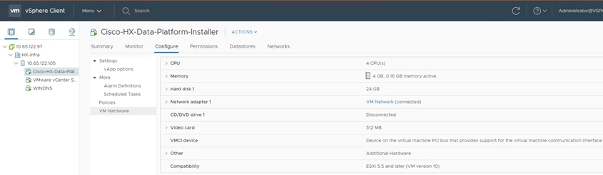
Deploy Cisco HyperFlex Data Platform Installer VM
To deploy HyperFlex Data Platform (HXDP) installer VM, follow these steps:
1. Download the latest installer OVA from Cisco.com at: https://software.cisco.com/download/home/286319572/type/286305994/release/4.0(2a)?catid=286305510
2. To deploy OVA to an existing host in the environment. Use either users existing vCenter Thick Client or vSphere Web Client to deploy OVA on ESXi host.
3. Log into vCenter web client via vCenter management IP address: https://<FQDN or IP address for VC>.
4. Select ESXi host under hosts and cluster then choose the ESXi host to deploy HX DP installer OVA.
5. Right-click the ESXi host and select the option Deploy OVF Template.
6. Browse for the HX DP OVA and click Next.
7. Enter name for OVF template to deploy, select datacenter. Click Next.
8. Review and verify the details for OVF template to deploy, click Next.
9. Select virtual disk format, VM storage policy set to datastore default, select datastore for OVF deployment. Click Next.
10. Select Network adapter destination port-group. Click Next.
11. Fill up the parameters requested for hostname, gateway, DNS, IP address, and netmask. Alternatively, leave all blank for a DHCP assigned address.
12. Review settings selected part of the OVF deployment, click the checkbox for Power on after deployment. Click Finish.
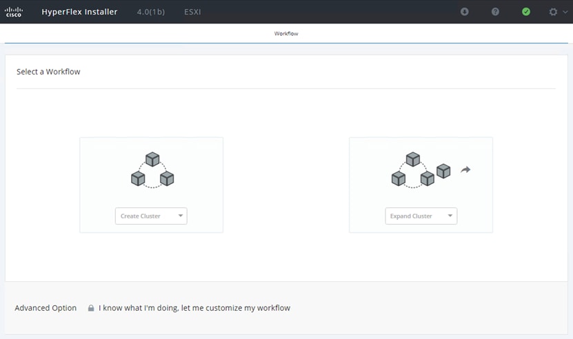
Cisco HyperFlex Cluster Creation
To create a HyperFlex cluster, follow these steps:
1. Select the workflow for cluster creation to deploy a new HyperFlex cluster on Cisco HXAF240c-M5SX nodes.
2. On the credentials page, enter the access details for Cisco UCS Manager and vCenter server. Click Continue.
3. Choose the top-most check box at the top right corner of the HyperFlex installer to select all unassociated servers. Click Continue after completing server selection.
4. Enter the Details for the Cisco UCS Manager Configuration:
a. Enter VLAN ID for hx-inband-mgmt, hx-storage-data, hx-vmotion, vm-network.
b. MAC Pool Prefix: The prefix to use for each HX MAC address pool. Please select a prefix that does not conflict with any other MAC address pool across all Cisco UCS domains.
c. The blocks in the MAC address pool will have the following format:
§ ${prefix}:${fabric_id}${vnic_id}:{service_profile_id}
§ The first three bytes should always be “00:25:B5”.
5. Enter range of IP address to create a block of IP addresses for external management and access to CIMC/KVM.
6. Cisco UCS firmware version is set to 4.0.x which is the required Cisco UCS Manager release for HyperFlex 4.0.x installation.
7. Enter HyperFlex cluster name.
8. Enter the Org name to be created in Cisco UCS Manager. Click Continue.
9. To configure the Hypervisor settings, follow these steps:
a. In the Configure common Hypervisor Settings section, enter:
§ Subnet Mask
§ Gateway
§ DNS server(s)
b. In the Hypervisor Settings section:
§ Select check box Make IP Address and Hostnames Sequential if they are following in sequence.
§ Provide the IP Address.
§ Provide the Host Name or enter Static IP address and Host Names manually for each node. Click Continue.
10. To add the IP addresses, follow these steps:
a. On the IP Addresses page, check the box Make IP Addresses Sequential or enter the IP address manually for each node for the following requested values:
§ Storage Controller/Management
§ Hypervisor/Data
§ Storage Controller/Data
b. Enter subnet and gateway details for the Management and Data subnets configured. Click Continue to proceed.
11. On the Cluster Configuration page, enter the following:
a. Cluster Name
b. Set Replication Factor: 2 or 3
c. Controller VM password
d. vCenter Configuration
§ vCenter Datacenter name
§ vCenter Cluster name
e. System Services
§ DNS Server(s)
§ NTP Server(s)
§ Time Zone
f. Auto Support
§ Click the check box for Enable Auto Support
§ Mail Server
§ Mail Sender
§ ASUP Recipient(s)
g. Advanced Networking
§ Management vSwitch
§ Data vSwitch
h. Advanced Configuration
§ Click the check box to Optimize for VDI only deployment
§ Enable jumbo Frames on Data Network
§ Clean up disk partitions (if the cluster was in use previously)
i. vCenter Single-Sign-On server
12. The configuration details can be exported to a JSON file by clicking the down arrow icon in the top right corner of the Web browser page.
13. Configuration details can be reviewed on Configuration page on right side section. Verify entered details for IP address entered in Credentials page, server selection for cluster deployment and creation workflow, Cisco UCS Manager configuration, Hypervisor Configuration, IP addresses.
14. Click Start after verifying the details.
When the installation workflow begins, it will go through the Cisco UCS Manager validation.
15. After a successful validation, the workflow continues with the Cisco UCS Manager configuration.
16. After a successful Cisco UCS Manager configuration, the installer proceeds with the Hypervisor configuration.
17. After a successful Hypervisor configuration, deploy validation task is performed which checks for required component and accessibility prior Deploy task is performed on Storage Controller VM.
18. Installer performs deployment task after successfully validating Hypervisor configuration.
19. After a successful deployment of the ESXi hosts configuration, the Controller VM software components for HyperFlex installer checks for validation prior to creating the cluster.
20. After a successful validation, the installer creates and starts the HyperFlex cluster service.
21. After a successful HyperFlex Installer VM workflow completion, the installer GUI provides a summary of the cluster that has been created.
22. Click Launch vSphere Web Client.
Cisco HyperFlex installer creates and configures a controller VM on each converged node. Naming convention is used as “stctlvm-<Serial Number for Cisco UCS Node>”
![]() Do not to change the name or any resource configuration for the controller VM.
Do not to change the name or any resource configuration for the controller VM.
![]() For more information about the Cisco HyperFlex installation steps with screenshots, see: https://www.cisco.com/c/en/us/td/docs/unified_computing/ucs/UCS_CVDs/hyperflex_30_vsi_esxi.html#_Toc514225549. Please note that this link is for Cisco HyperFlex 3.0, users can refer to this guide to verify their configuration with the screenshots.
For more information about the Cisco HyperFlex installation steps with screenshots, see: https://www.cisco.com/c/en/us/td/docs/unified_computing/ucs/UCS_CVDs/hyperflex_30_vsi_esxi.html#_Toc514225549. Please note that this link is for Cisco HyperFlex 3.0, users can refer to this guide to verify their configuration with the screenshots.
Run Cluster Post Installation Script
After a successful installation of HyperFlex cluster, run the post_install script by logging into the Data Platform Installer VM via SSH, using the credentials configured earlier.
A built-in post install script automates basic final configuration tasks like enabling HA/DRS on HyperFlex cluster, configuring VMkernel for vMotion interface, creating datastore for ESXi logging, and so on.
To run the script, use any tool of choice to make a secure connection to the Cisco HyperFlex Data Platform installer using it’s IP address and port 22.
1. Authenticate with the credentials provided earlier. (user name: root with user’s password if user did not change the defaults.)
2. When authenticated, enter post_install at the command prompt, then press Enter.
3. Provide a valid vCenter administrator user name and password and the vCenter url IP address.
4. Type y for yes to each of the prompts that follow and choose yes at the prompt to Add VM network VLANs if user needs to add more VLANs. This is required for allowing other VLANs that are required for three-arm interfaces created for F5 load balancer.
5. Provide the requested user credentials, the vMotion netmask, VLAN ID and an IP address on the vMotion VLAN for each host when prompted for the vmkernel IP.
![]() For more details on running the post installation script, go to: https://www.cisco.com/c/en/us/td/docs/unified_computing/ucs/UCS_CVDs/hx_4_vsi_vmware_esxi.html#_Toc24465202
For more details on running the post installation script, go to: https://www.cisco.com/c/en/us/td/docs/unified_computing/ucs/UCS_CVDs/hx_4_vsi_vmware_esxi.html#_Toc24465202
Log into HyperFlex Connect
To configure the Cisco HyperFlex Cluster, follow these steps:
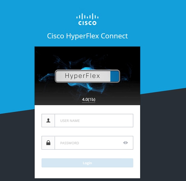
1. Log into HX Installer VM through a web browser: http://<Installer_VM_IP_Address>
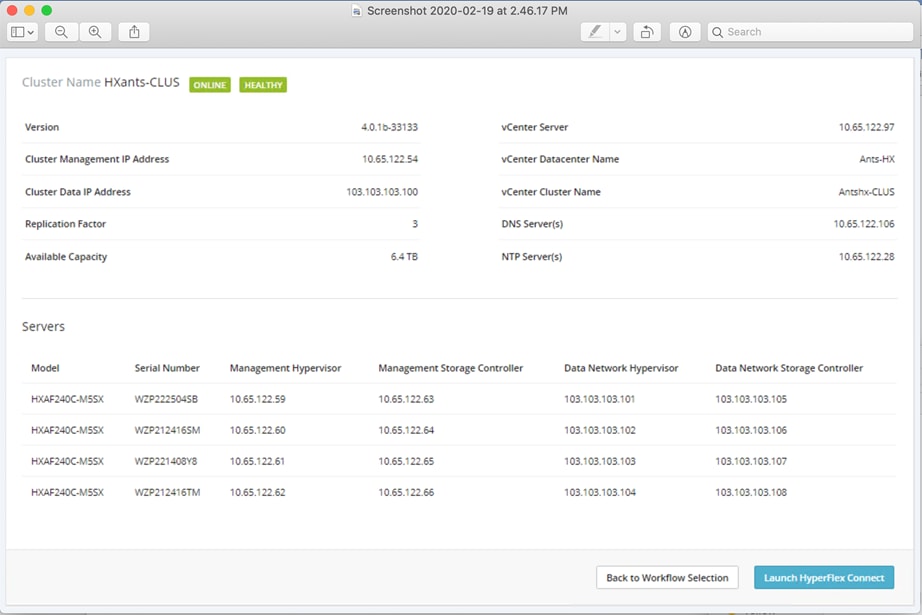
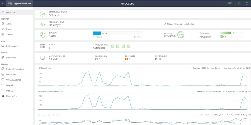
2. HyperFlex Connect dashboard shows the details about the cluster status, capacity, and performance.
3. System Information page provides details on System Overview, Nodes and Disks.
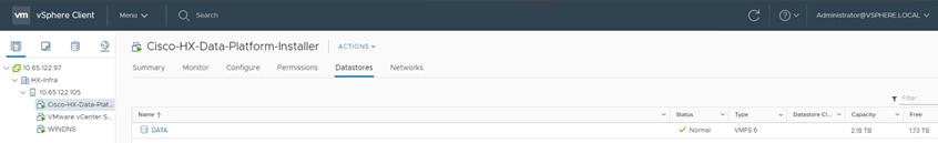
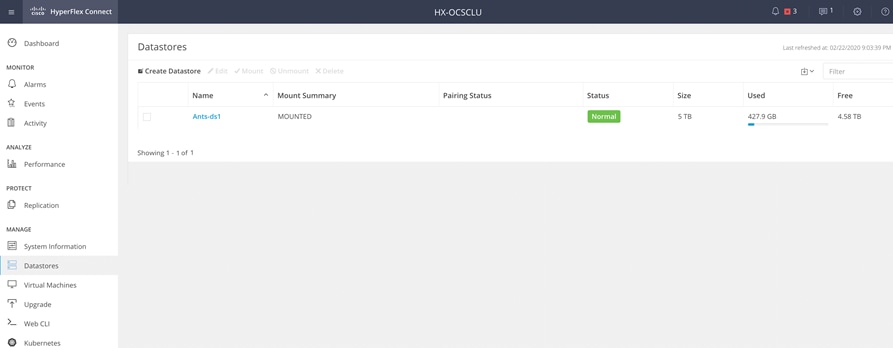
4. Click Datastores and click Create Datastore to create datastore for Anthos GKE on-prem deployment.
Adding a Converged Node through HX Installer
Cisco HyperFlex allows users to expand their cluster non-disruptively. Converged, compute only and storage nodes can be independently scaled. In this solution we show how a converged node can be added to the existing cluster.
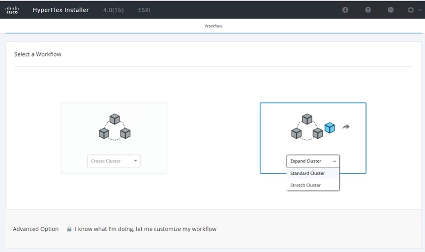
The HyperFlex installer has a wizard for Cluster Expansion with converged nodes. This procedure is very similar to the initial HyperFlex cluster setup. The following process assumes a new Cisco HX node has been ordered, therefore it is pre-configured from the factory with the proper hardware, firmware, and ESXi hypervisor installed. To add converged storage nodes to an existing HyperFlex cluster, follow these steps:
1. On the HyperFlex installer webpage click the dropdown menu for Expand Cluster, then click Standard Cluster.
2. Enter the Cisco UCS Manager and vCenter DNS hostname or IP address, the admin usernames, and the passwords for the UCS domain of the existing cluster nodes. Optionally, user can import a JSON file that has the configuration information. Click Continue.
3. Select the HX cluster to expand and enter the cluster management password, then click Continue.
4. Select the unassociated HX-series server to be added to the existing HX cluster, then click Continue.
5. On the UCSM Configuration page, all the settings should be pre-populated with the correct values for the existing cluster. The only value that is required is to create an additional IP address block for the hx-ext-mgmt IP address pool. Enter a range of IP addresses sufficient to assign to the new server, along with the subnet mas and gateway address, then click Continue.
6. Enter the subnet mask, gateway, DNS, and IP addresses for the Hypervisors (ESXi hosts) as well as host names, then click Continue. The IPs will be assigned through Cisco UCS Manager to the ESXi systems.
7. Enter the additional IP addresses for the Management and Data networks of the new node. Enter the current password that is set on the Controller VMs. Select Clean up disk partitions if it is not a first time installation. Click Start.
8. Validation of the configuration now starts and automatically proceeds with the configuration process if there are no warnings or errors.
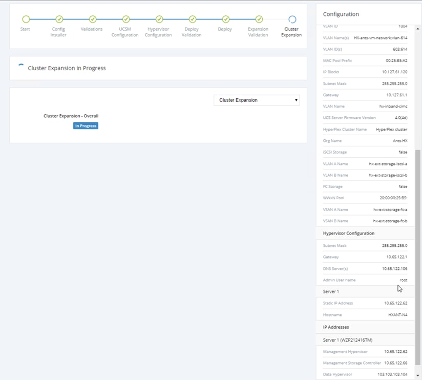
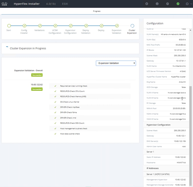
9. Once HX installer completes the deployment and summary screen can be seen showing the node added into the existing cluster.
10. On HX Connect, enable Persistent Volumes for Kubernetes by clicking Enable, enables Kubernetes on all nodes (to the one newly added) to configure Cisco HyperFlex cluster to support Persistent Volumes for Kubernetes. After adding the node, Kubernetes will be only enabled partially till it is enabled again.
Upgrade Cisco HyperFlex Data Platform
To upgrade an existing Cisco HyperFlex system to the latest release, it is recommended to follow the guidelines provided here:
Anthos GKE on-prem Prerequisites
This subsection provides details on prerequisites for Anthos GKE on-prem deployment. The prerequisites for Anthos GKE on-prem include:
1. DNS server configuration.
2. Proxy server configuration (if the end user’s environment has web proxy).
3. L4 Load balancer configuration:
a. F5 load balancer – as integrated mode for Anthos GKE on-prem
b. Ha-proxy load balancer – as manual mode for Anthos GKE on-prem
4. White listing project on GCP.
5. Installing required software.
6. Creating admin workstation.
DNS Server Configuration
Users can leverage the existing DNS server in their environment for Anthos GKE on-prem. In this solution there is a dedicated VM running DNS using dnsmasq services for Anthos GKE on-prem. To configure DNS services, follow these steps:
1. Create a VM on Cisco HyperFlex.
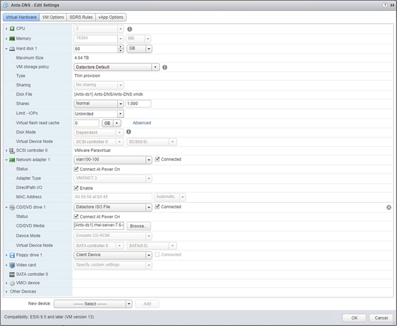
2. In this solution RHEL 7.6 is installed on the VM designated for DNS. Run yum install dnsmasq.
3. Add host entries at /etc/dnsmasq.d/hosts.
For example: in /etc/dnsmasq.d/hosts – add host and address in the following format:
#node ips
address=/hostname.domain/<ip>
address=/hostname.domain/<ip>
4. Open /etc/dnsmasq.conf file and add the nameserver ip for dnsmasq as shown below.
# forward all queries to following dns
server=<nameserver IP>
5. Add DNS service in firewall by running firewall-cmd --add-service=dns -–permanent.
6. Restart firewall service for the change to take effect by running systemctl restart firewalld.service.
7. Enable and start dnsmasq service by running systemctl enable dnsmasq.service and systemctl start dnsmasq.service.
8. Add local host in /etc/resolv.conf so that all the nodes participating in the Anthos GKE on-prem deployment points to this ip. And make sure to check the hostname resolution to verify dnsmasq is set correctly.
# Generated by NetworkManager
search <domain>
nameserver 127.0.0.1
nameserver <dns ip>
![]() Our lab setup is behind a web proxy, so we have configured a squid proxy service on the same node that is running dnsmasq service. Squid is a caching proxy for the web that supports HTTP, HTTPS, FTP and more. Its distinct advantages are caching frequently-requested pages to speed-up web page load times.
Our lab setup is behind a web proxy, so we have configured a squid proxy service on the same node that is running dnsmasq service. Squid is a caching proxy for the web that supports HTTP, HTTPS, FTP and more. Its distinct advantages are caching frequently-requested pages to speed-up web page load times.
L4 Load Balancer Configuration
Anthos GKE on-prem supports Integrated and Manual mode for configuring L4 load balancers. In this solution we will provide details on configuring both load balancers in integrated and manual modes.
F5 Load Balancer – as Integrated Mode for Anthos GKE on-prem
Anthos enables native integration with F5 Big-IP load balancers to expose services from each pod externally to the world. BIG-IP provides container ingress services (CIS). CIS provides platform-native integrations for BIG-IP devices from platform as a service (PaaS) providers like Kubernetes. This integration makes it possible to dynamically allocate BIG-IP L4-L7 services in container orchestration environments. Anthos uses a version of CIS to automatically provision L3/L4 load-balancing services on the BIG-IP platform while providing external access to apps deployed on GKE on-prem clusters.
Networking for the F5 Big-IP virtual appliance can be configured in a two-armed or three-armed configuration based on user’s network environment. The deployment in this document is based on the three-armed configuration. Three-armed configuration means that I have three interfaces (with three different vlans) for internal, external and ha of F5 load balancer. We have chosen three-armed to configure HA with two F5 Big-IPs as it is recommended to have F5 configured in HA for enterprise solutions.
Additional details on configuring the virtual appliance for use with Anthos can be found at: https://cloud.google.com/solutions/partners/installing-f5-big-ip-adc-for-gke-on-prem.
To deploy the F5 Big-IP Virtual Edition appliance, follow these steps:
1. Download the virtual application Open Virtual Appliance (OVA) file from F5 at: https://login.f5.com/resource/login.jsp?ctx=719748.
2. Right-click the Infrastructure Resource Pool and select Deploy OVF Template. A wizard launches and allows to select the OVA file that was just downloaded in step 1. Click Next.
3. Click Next to continue through each step and accept the default values for each screen presented until the storage selection screen is reached. CPU and Memory resources are set to 2CPUs and 4096 MB RAM in the OVA. In this solution we have restored the resource allocation to 2CPUs and 4GB RAM as we have limited 1Gbps throughput on F5 - https://support.f5.com/csp/article/K14810. Users can choose to change the resource allocation based on their needs. Select the VM_Datastore that was created earlier, and then click Next.
4. The next screen presented by the wizard allows the user to customize the virtual networks to use in the environment. Select VM_Network for the External field and select Management_Network for the Management field. Internal and HA are used for advanced configurations for the F5 Big-IP appliance and are not configured. Click Next.
5. Review the summary screen for the appliance, and, if all the information is correct, click Finish to start the deployment.
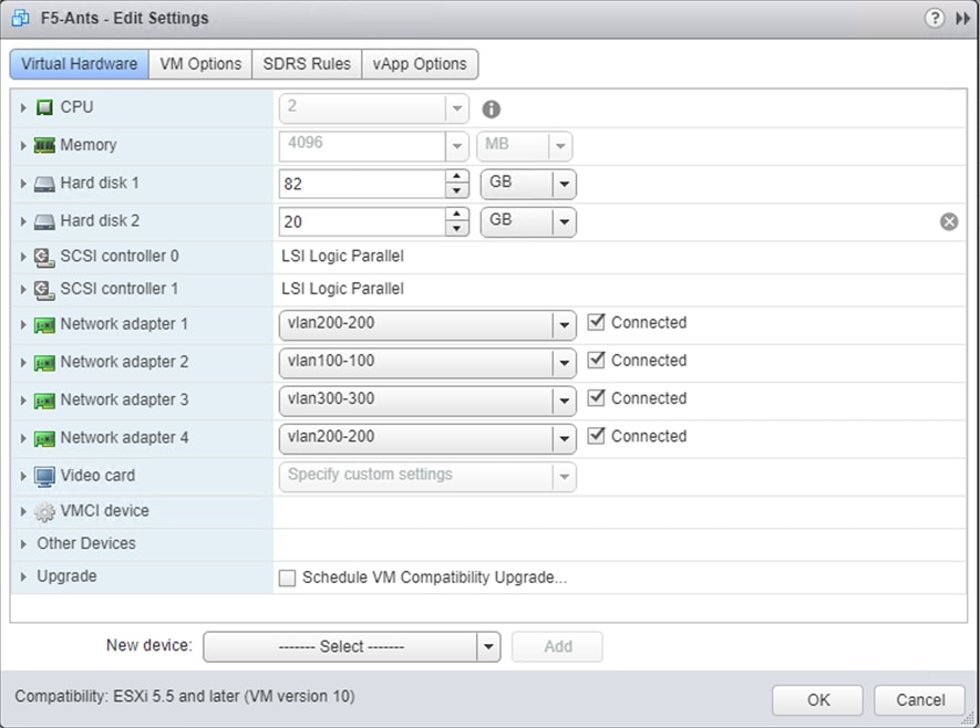
6. After the virtual appliance is deployed, right-click it and power it up. It receives a DHCP address on the management network and the DHCP configuration needs to be disabled. The appliance is Linux-based and it has VMware Tools deployed. To disable the DHCP configuration, assign the management IP and set the DNS, follow these steps:
a. Log into the F5 console using the default login credentials root/default.
§ Type tmsh in the command prompt.
§ To disable DHCP, type command modify sys global-settings mgmt-dhcp disabled.
§ Type save /sys config, to save the change in the configuration.
§ While in tmsh, type create /sys management-ip <ip>/255.255.255.0 (or) create /sys management-ip <ip>/24 to assign the management IP.
§ To set the default IP, type create /sys management-route default gateway <gateway ip address>.
§ To save the configuration, type save /sys config partitions all.
7. Open a web browser and connect to the appliance at the management IP address assigned from the previous step. The default login is admin/admin and after the first login the appliance takes the user to the license page. Click Activate to begin. Paste either the 30-day evaluation license key or the permanent license acquired during appliance procurement. Click Next.
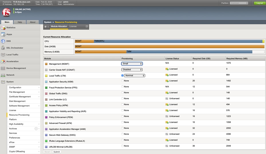
![]() For the device to perform activation, the network defined on the management interface must be able to reach the internet.
For the device to perform activation, the network defined on the management interface must be able to reach the internet.
8. On the next screen, the End User License Agreement (EULA) is presented. If the terms in the license are acceptable, click Accept.
9. Once the license is applied, the user is prompted to set a new password for admin and root access.
10. Log back in and navigate to VLANs > Network. Create VLANs with appropriate tags that are visible on the interfaces. These tags can be verified from vCenter on the network adapters configured for F5 BIG IP.
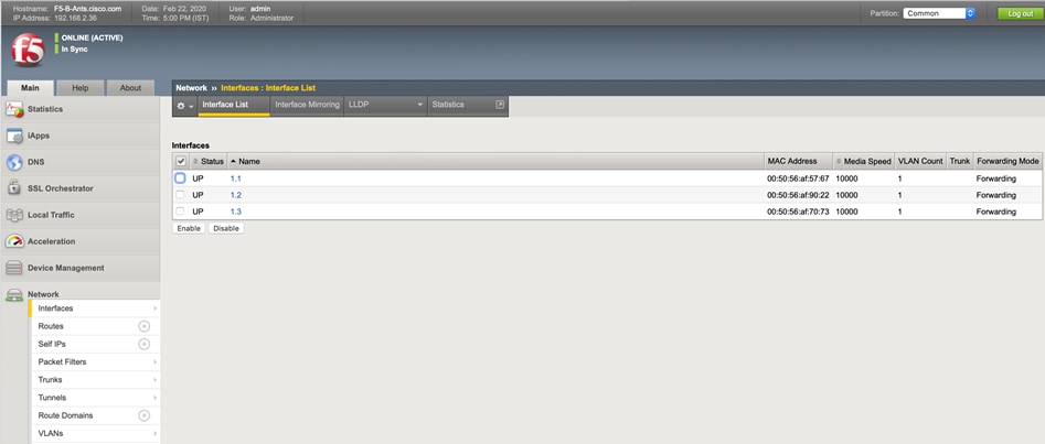
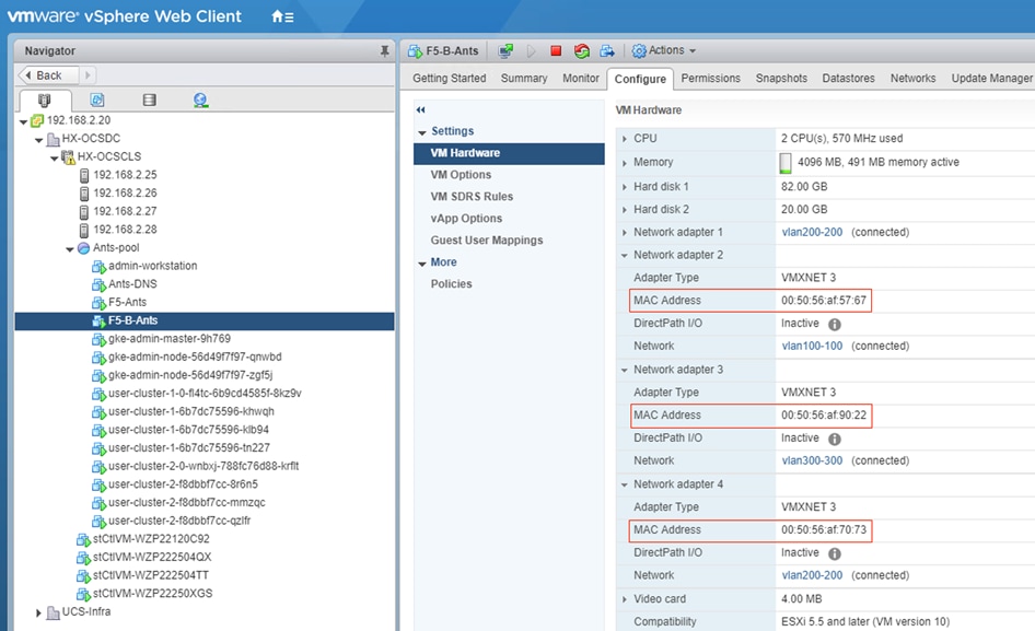
11. Create Self IPs and associate them with their respective VLANs. Assign IP address for internal, external and HA, and choose the appropriate vlan from the VLAN/ Tunnel field drop-down list.
12. Create partitions for admin cluster and user clusters under Systems > Users > Partition List. This is a manual process where the administrator creates two partitions (administrative boundaries) to keep the virtualized load-balancers separated from one another and the rest of the Big-IP system. One partition is for the admin cluster and the other is for the first user cluster. Each additional user cluster will need its own F5 partition.
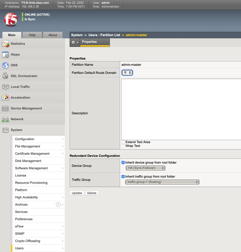
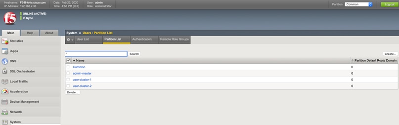
13. High availability users can configure two F5 BIG IP VE in active-active or active-standby mode. In this solution we configured F5 for HA in active-standby mode.
14. Repeat steps 1-13 to configure the second F5 BIG IP. Once the second F5 is ready, follow these steps to sync the devices to make them active-active or active-standby. In this solution we used F5s in active-standby mode.
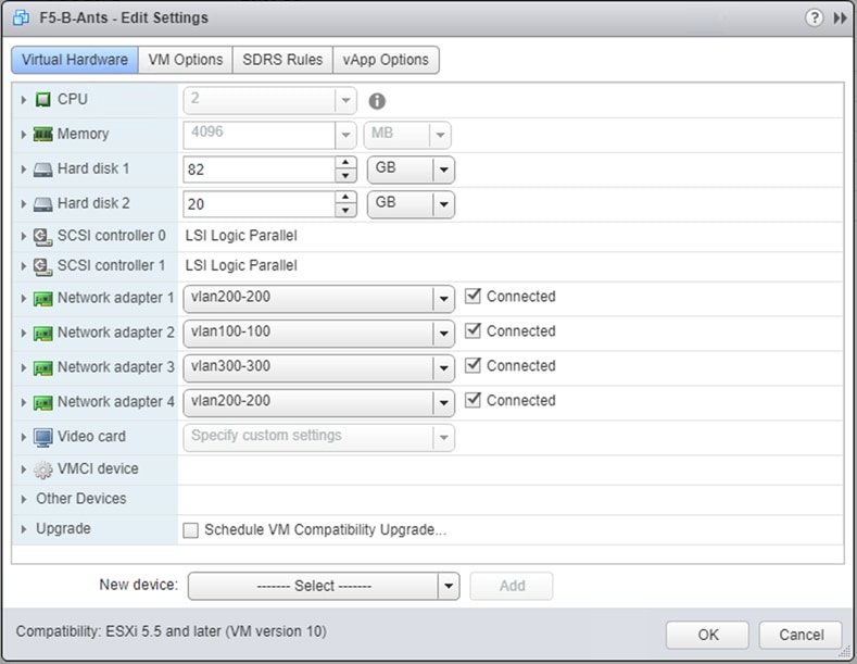
15. As mentioned in the previous steps while creating VLANs and Self IPs, user would have created one for HA as well as per the steps. The user is required to choose an unused subnet <IP>/24 for HA heartbeat to work. User now configure active device and peer in the same subnet. Make sure the configured Self IPs are non-floating.
16. Specify an IP address that is used to synchronize their configuration objects by other devices in the device group to the local device. To do this, follow these steps:
a. Click Device Management > Devices
b. Click the device name of the currently logged in device.
c. Under Device Connectivity menu, choose ConfigSync.
d. Choose the self IP address configured earlier and Update. This address must be a non-floating self IP address and not a management IP address.
e. On the peer device, choose <HA IP> for Config Sync.
17. Add peer device in the Device Trust.
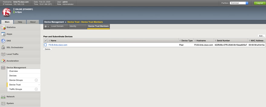
18. The Devices displays the devices list with the peer device included.
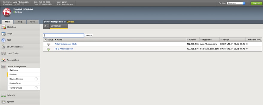
19. In Device Groups create sync failover. Note the “Type”, “ConfigSync”, “ConfigSync status” and “Members” being updated.
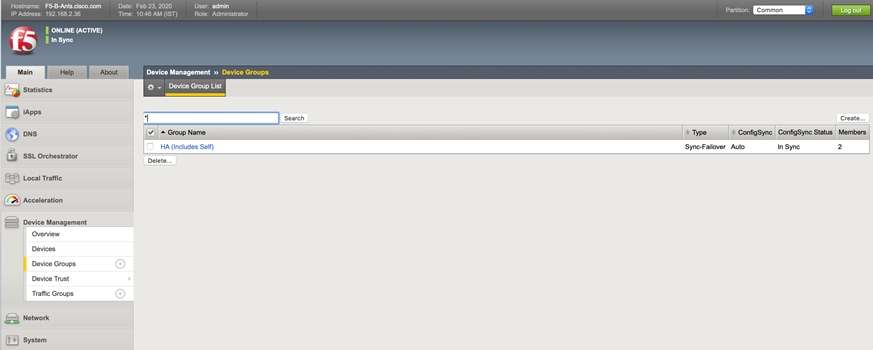
20. Once the sync failover is set on both the F5 devices, sync status on the active and standby devices can be viewed as shown in the screenshots of two devices in sync:
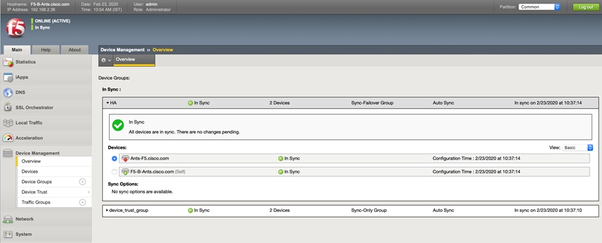
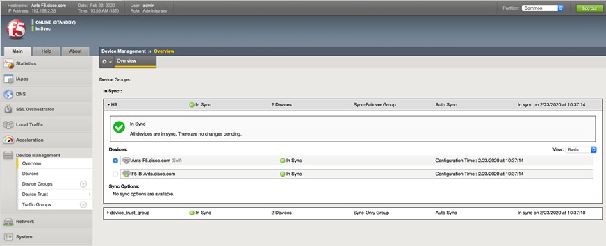
HAProxy Load Balancer – as Manual Mode for Anthos GKE on-prem
Anthos GKE on-prem supports users to provide an L4 load balancer of their choice. This is termed as manual mode of configuration as there is no prior integration available with GKE on-prem and users need to configure the load balancer entirely on their own.
In this solution we picked up HAProxy for manual mode since it is a free, very fast and reliable solution offering high availability and load balancing for TCP and HTTP based applications. It is particularly suited for very high traffic web sites and powers quite a number of the world's most visited websites. Over the years it has become the de-facto standard opensource load balancer. It is now shipped with most mainstream Linux distributions, and is often deployed by default in cloud platforms.
To configure HAProxy load balancer, follow these steps:
1. Create two VMs for HAProxy configuration for high availability deployment. In this solution the two VMs are based on Ubuntu 18.04 OS.
2. Users can allocate minimum resources as deployed in this solution. We used a minimalistic approach with (2 CPUs and 4G RAM). Users need to evaluate the requirement at their end and allocate resources as required.
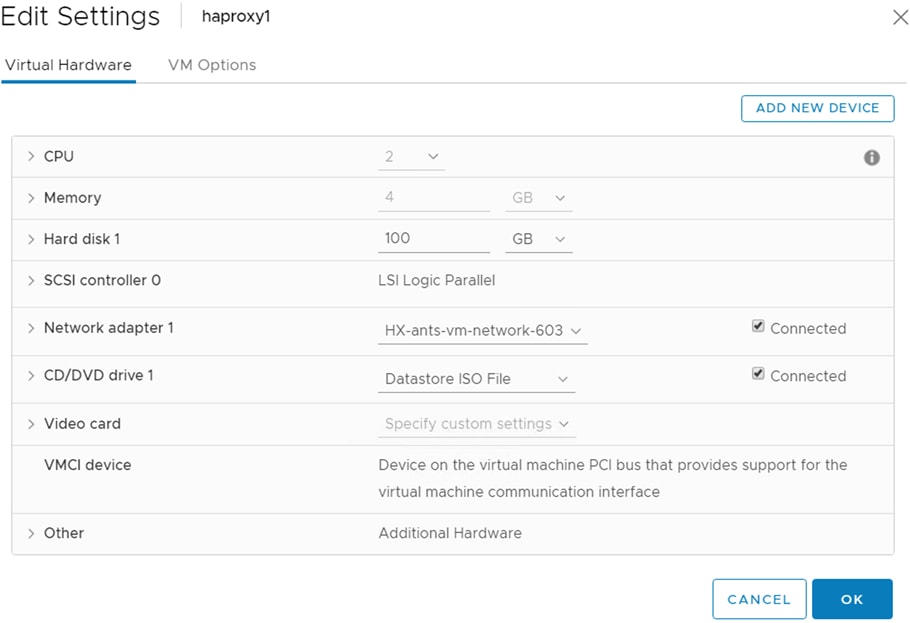
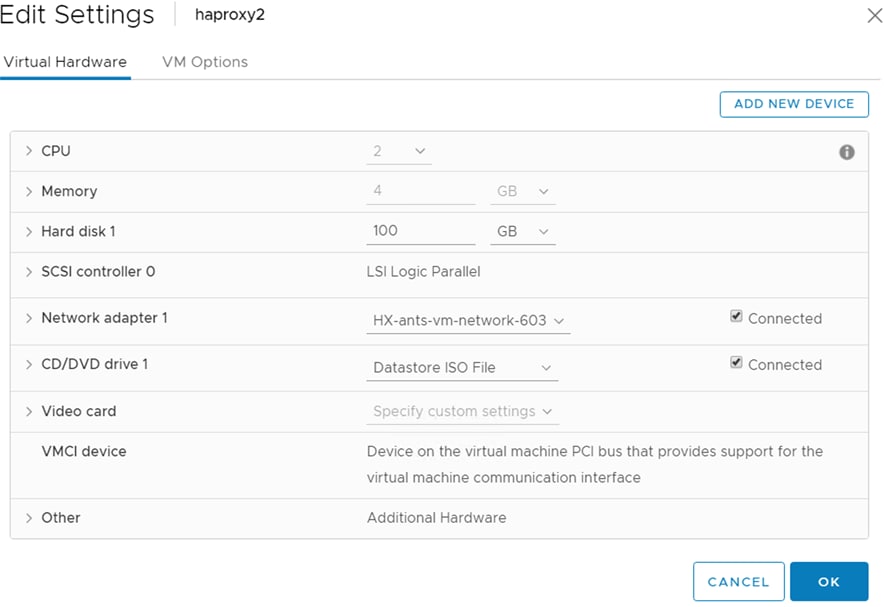
3. Install HAProxy by running command sudo apt-get install haproxy.
4. To start with, enable haproxy connect by running the command setsebool -P haproxy_connect_any=1.
5. For manual load balancing, create Virtual IPs (VIPs) on the VM before running HAProxy. The different VIPs to be added will serve for admin control plane, admin ingress, user control plane, user ingress, additional user control plane and additional user ingress. To enable interfaces, modify the /etc/netplan/<interface.yaml> by adding addresses as:
# This file describes the network interfaces available on your system
# For more information, see netplan(5).
network:
version: 2
renderer: networkd
ethernets:
ens192:
addresses: [ 10.65.122.77/24, 10.65.122.78/24, 10.65.122.79/24, 10.65.122.83/24, 10.65.122.84/24, 10.65.122.85/24, 10.65.122.161/24, 10.65.122.190/24, 10.65.122.191/24, 10.65.122.192/24 ]
gateway4: 10.65.122.1
nameservers:
search: [ cisco.com ]
addresses:
- "10.105.56.241"
![]() In ubuntu 18.04 interfaces are yaml files. User needs to edit the interface.yaml to add addresses as shown above.
In ubuntu 18.04 interfaces are yaml files. User needs to edit the interface.yaml to add addresses as shown above.
6. For the modification to take effect, run sudo netplan apply.
7. Now edit the haproxy config file at /etc/haproxy/haproxy.cfg. This file needs to include the addresses with specific ports for admin and user clusters for Anthos GKE on-prem. The following is the example configuration used in this solution:
global
log /dev/log local0
log /dev/log local1 notice
chroot /var/lib/haproxy
stats socket /run/haproxy/admin.sock mode 660 level admin
stats timeout 30s
user haproxy
group haproxy
daemon
# Default SSL material locations
ca-base /etc/ssl/certs
crt-base /etc/ssl/private
# Default ciphers to use on SSL-enabled listening sockets.
# For more information, see ciphers(1SSL). This list is from:
# https://hynek.me/articles/hardening-your-web-servers-ssl-ciphers/
ssl-default-bind-ciphers ECDH+AESGCM:DH+AESGCM:ECDH+AES256::RSA+AES:RSA+3DES:!aNULL:!MD5:!DSS
ssl-default-bind-options no-sslv3
defaults
log global
mode tcp
option tcplog
option dontlognull
timeout connect 5000
timeout client 50000
timeout server 50000
errorfile 400 /etc/haproxy/errors/400.http
errorfile 403 /etc/haproxy/errors/403.http
errorfile 408 /etc/haproxy/errors/408.http
errorfile 500 /etc/haproxy/errors/500.http
errorfile 502 /etc/haproxy/errors/502.http
errorfile 503 /etc/haproxy/errors/503.http
errorfile 504 /etc/haproxy/errors/504.http
frontend stats
bind 10.65.122.111:8000
mode http
stats enable
stats uri /
stats refresh 60s
frontend admin-cp
bind 10.65.122.83:443
default_backend admin-cp-backend
backend admin-cp-backend
balance roundrobin
mode tcp
server host-1 10.65.122.67:30968 check
server host-2 10.65.122.68:30968 check
server host-3 10.65.122.69:30968 check
server host-4 10.65.122.70:30968 check
server host-5 10.65.122.71:30968 check
server host-6 10.65.122.72:30968 check
server host-7 10.65.122.73:30968 check
frontend admin-ingress-http
bind 10.65.122.84:80
default_backend admin-ingress-http-backend
backend admin-ingress-http-backend
balance roundrobin
mode tcp
server host-1 10.65.122.67:32527 check
server host-2 10.65.122.68:32527 check
server host-3 10.65.122.69:32527 check
server host-4 10.65.122.70:32527 check
server host-5 10.65.122.71:32527 check
server host-6 10.65.122.72:32527 check
server host-7 10.65.122.73:32527 check
frontend admin-ingress-https
bind 10.65.122.84:443
default_backend admin-ingress-https-backend
backend admin-ingress-https-backend
balance roundrobin
mode tcp
server host-1 10.65.122.67:30139 check
server host-2 10.65.122.68:30139 check
server host-3 10.65.122.69:30139 check
server host-4 10.65.122.70:30139 check
server host-5 10.65.122.71:30139 check
server host-6 10.65.122.72:30139 check
server host-7 10.65.122.73:30139 check
frontend uc1-cp
bind 10.65.122.85:443
default_backend uc1-cp-backend
backend uc1-cp-backend
balance roundrobin
mode tcp
server host-1 10.65.122.67:30562 check
server host-2 10.65.122.68:30562 check
server host-3 10.65.122.69:30562 check
server host-4 10.65.122.70:30562 check
server host-5 10.65.122.71:30562 check
server host-6 10.65.122.72:30562 check
server host-7 10.65.122.73:30562 check
frontend uc1-ingress-http
bind 10.65.122.78:80
default_backend uc1-ingress-http-backend
backend uc1-ingress-http-backend
balance roundrobin
mode tcp
server host-11 10.65.122.53:30243 check
server host-12 10.65.122.55:30243 check
server host-13 10.65.122.56:30243 check
server host-14 10.65.122.57:30243 check
server host-15 10.65.122.58:30243 check
server host-16 10.65.122.74:30243 check
server host-17 10.65.122.75:30243 check
frontend uc1-ingress-https
bind 10.65.122.78:443
default_backend uc1-ingress-https-backend
backend uc1-ingress-https-backend
balance roundrobin
mode tcp
server host-11 10.65.122.53:30879 check
server host-12 10.65.122.55:30879 check
server host-13 10.65.122.56:30879 check
server host-14 10.65.122.57:30879 check
server host-15 10.65.122.58:30879 check
server host-16 10.65.122.74:30879 check
server host-17 10.65.122.75:30879 check
frontend uc2-cp
bind 10.65.122.79:443
default_backend uc2-cp-backend
backend uc2-cp-backend
balance roundrobin
mode tcp
server host-1 10.65.122.67:30563 check
server host-2 10.65.122.68:30563 check
server host-3 10.65.122.69:30563 check
server host-4 10.65.122.70:30563 check
server host-5 10.65.122.71:30563 check
server host-6 10.65.122.72:30563 check
server host-7 10.65.122.73:30563 check
frontend uc2-ingress-http
bind 10.65.122.161:80
default_backend uc2-ingress-http-backend
backend uc2-ingress-http-backend
balance roundrobin
mode tcp
server host-21 10.65.122.162:30244 check
server host-22 10.65.122.163:30244 check
server host-23 10.65.122.164:30244 check
server host-24 10.65.122.165:30244 check
server host-25 10.65.122.166:30244 check
server host-26 10.65.122.167:30244 check
server host-27 10.65.122.168:30244 check
frontend uc2-ingress-https
bind 10.65.122.161:443
default_backend uc2-ingress-https-backend
backend uc2-ingress-https-backend
balance roundrobin
mode tcp
server host-21 10.65.122.162:30880 check
server host-22 10.65.122.163:30880 check
server host-23 10.65.122.164:30880 check
server host-24 10.65.122.165:30880 check
server host-25 10.65.122.166:30880 check
server host-26 10.65.122.167:30880 check
server host-27 10.65.122.168:30880 check
8. Now start the haproxy service by running sudo service haproxy restart.
9. Configure the second HAProxy VM by completing the steps as followed for the first HAProxy VM.
10. Once both the VMs are up and running with HAProxy configured, connect the devices for HA configuration.
11. To make the HA enabled for the two VMs, keepalived should be installed and configured. To install keepalived run sudo apt-get install keepalived.
12. Modify the keepalived config file at /etc/keepalived/. User need to provide the vip here to access HAProxy web page. On this first HAProxy VM configure the keepalived.conf as follows:
vrrp_script chk_haproxy { # Requires keepalived-1.1.13
script "killall -0 haproxy" # cheaper than pidof
interval 2 # check every 2 seconds
weight 2 # add 2 points of prio if OK
}
vrrp_instance VI_1 {
state MASTER
interface ens192
virtual_router_id 101
priority 101
advert_int 1
track_script {
chk_haproxy
}
virtual_ipaddress {
10.65.122.111
}
} 111
13. Modify the keepalived.conf on the second HAProxy VM as follows:
vrrp_script chk_haproxy { # Requires keepalived-1.1.13
script "killall -0 haproxy" # cheaper than pidof
interval 2 # check every 2 seconds
weight 2 # add 2 points of prio if OK
}
vrrp_instance VI_1 {
state MASTER
interface ens192
virtual_router_id 101
priority 100
advert_int 1
track_script {
chk_haproxy
}
virtual_ipaddress {
10.65.122.111
}
}
![]() virtual_router_id should be same on both LB1 and LB2 servers. The priority on the LB1 should be higher than the LB2.
virtual_router_id should be same on both LB1 and LB2 servers. The priority on the LB1 should be higher than the LB2.
14. Start the keepalived service by running sudo service keepalived start.
15. Users can now access HAProxy web page using the configured vip as shown below.
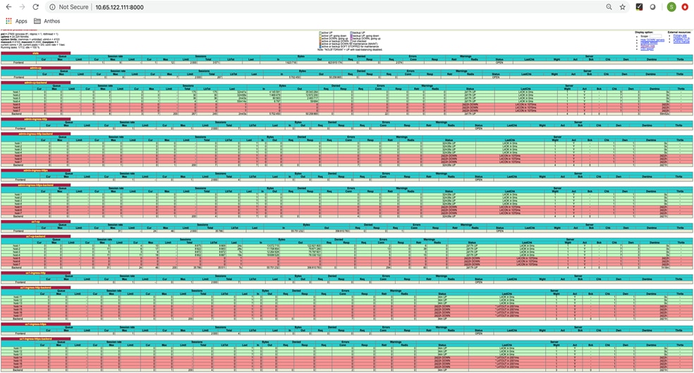
White Listing Project on GCP
Anthos GKE on-prem deployment starts with several prerequisites that the user must prepare to deploy the solution and access it afterward. Each of these steps are described in depth in the Anthos GKE on-prem Guide here: https://cloud.google.com/anthos/gke/docs/on-prem/archive/1.2. To prepare the environment for the deployment of Anthos GKE on-prem, follow these steps:
1. Create a Google Cloud project and get it whitelisted by following the instructions available at: https://cloud.google.com/resource-manager/docs/creating-managing-projects#creating_a_project.
2. Create a deployment workstation from which to manage the installation of Anthos GKE on-prem. The deployment workstation can be Linux, MacOS, or Windows. In this solution, Red Hat Enterprise Linux 7.6 is used.
![]() In this deployment validation we have used the DNS server as the deployment workstation. This deployment workstation can be in the Cisco HyperFlex environment or outside of it. The only requirement is that it must be able to successfully communicate with the deployed VMware vCenter Server and the internet to function correctly.
In this deployment validation we have used the DNS server as the deployment workstation. This deployment workstation can be in the Cisco HyperFlex environment or outside of it. The only requirement is that it must be able to successfully communicate with the deployed VMware vCenter Server and the internet to function correctly.
Installing Required Software
1. Install Google Cloud SDK as instructed in Google document at: https://cloud.google.com/sdk/install for interactions with Google Cloud. It can be downloaded as an archive of binaries for manual install or installed by either the apt-get (Ubuntu/Debian) or yum (RHEL) package managers.
2. After the user has installed Cloud SDK using one of the methods above, the user can use commands in the gcloud components command group to manage the installation. This includes viewing installed components, adding and removing components, and upgrading to a new version (or downgrading to a specific version) of Cloud SDK. We have installed Google Cloud SDK by running the command yum install google-cloud-sdk.
3. Install govc, the CLI for VMware vSphere. Installing govc allows users to interact directly with the management of VMware vCenter. govc is available as a pre-packaged binary in a gzip format for download. For installation, the user must download the gzip archive, unzip, and copy the resulting binary to a local path directory such as /usr/local/bin. To install govc, run the following commands:
# wget https://github.com/vmware/govmomi/releases/download/v0.20.0/govc_linux_amd64.gz
# gunzip govc_linux_amd64.gz
# sudo cp govc_linux_amd64 /usr/local/bin/govc
4. Install Hashicorp Terraform. Terraform is used to automate VM deployment in a VMware vSphere environment in this solution and is used to deploy the Anthos admin workstation shown in a later step. Terraform can be downloaded as a zip archive and unzipped, and the resulting binary can be copied to a directory in the local user’s path. To install Terraform, run the following commands:
# wget https://releases.hashicorp.com/terraform/0.12.13/terraform_0.12.13_linux_amd64.zip
# unzip terraform_0.12.13_linux_amd64.zip
# cp terraform /usr/local/bin
Gcloud Authentication
With the workstation configured, users can login to Google Cloud with their credentials. To do so, enter the login command from the deployment workstation and retrieve a link that can be copied and pasted into a browser to allow interactive sign-in to Google services. After the user is logged in, the web page presents a code that can be copy and pasted back into the deployment workstation at the prompt to authenticate the user with their account. To authenticate to Google Cloud run gcloud auth login. User will be prompted to set their project. To set the project run gcloud config set project PROJECT_ID, where PROJECT_ID is the user’s white listed project name with a unique auto generated id.
Creating Service Accounts
Prior to installing Anthos GKE on-prem, user must create four service accounts, each with a specific purpose in interacting with Google Cloud. Table 4 lists the accounts and their purposes.
Table 4 Google Cloud’s Anthos Service Accounts
| Account name |
Purpose |
| access-service-account |
Used to download the Anthos GKE on-prem binaries from Cloud Storage |
| register-service-account |
Used to register Anthos GKE on-prem user clusters to the Google Cloud console |
| connect-service-account |
Used to maintain the connection between Anthos GKE on-prem user clusters and the Google Cloud |
| stackdriver-service-account |
Used to write logging and monitoring data to Stackdriver |
Each account is assigned an email address that references user’s approved Google Cloud project name. Run the following commands to create the service accounts:
# gcloud iam service-accounts create access-service-account
# gcloud iam service-accounts create register-service-account
# gcloud iam service-accounts create connect-service-account
# gcloud iam service-accounts create stackdriver-service-account
To see all the created service accounts run the command:
# gcloud iam service-accounts list
Users are expected to enable several APIs so that their environment can communicate with Google Cloud. The Anthos GKE on-prem cluster must be able to access https://www.googleapis.com and https://gkeconnect.googleapis.com to function as expected. It is important to note that the VM_Network configured for Anthos GKE cluster has internet access. To enable the necessary APIs, run the following command:
# gcloud services enable \
cloudresourcemanager.googleapis.com \
container.googleapis.com \
gkeconnect.googleapis.com \
gkehub.googleapis.com \
serviceusage.googleapis.com \
stackdriver.googleapis.com \
monitoring.googleapis.com \
logging.googleapis.com \
anthosgke.googleapis.com
Finally, users need to prepare the environment to deploy Anthos by providing certain privileges to the service accounts that were created. To assign required roles, follow these steps:
1. Assign the roles “gkehub.admin” and “serviceuseage.serviceUsageViewer” to register-service-account.
# gcloud projects add-iam-policy-binding <user's account> \
--member "serviceAccount: register-service-account@<user's account>.gserviceaccount.com”\
--role "roles/gkehub.admin"
# gcloud projects add-iam-policy-binding <user's account> \
--member "serviceAccount: register-service-account@<user's account>.gserviceaccount.com”\
--role "roles/serviceusage.serviceUsageViewer”
2. Assign the roles “gkehub.admin” to connect-service-account.
# gcloud projects add-iam-policy-binding <user's account> \
--member "serviceAccount: connect-service-account@<user's account>.gserviceaccount.com”\
--role "roles/gkehub.admin"
3. Assign roles “stackdriver.resourceMetadata.writer”, “logging.logWriter”, and “monitoring.metricWriter” to stackdriver-service-account.
# gcloud projects add-iam-policy-binding <user's account> \
--member "serviceAccount: stackdriver-service-account@<user's account>.gserviceaccount.com”\
--role "roles/stackdriver.resourceMetadata.writer"
# gcloud projects add-iam-policy-binding <user's account> \
--member "serviceAccount: stackdriver-service-account@<user's account>.gserviceaccount.com”\
--role "roles/logging.logWriter"
# gcloud projects add-iam-policy-binding <user's account> \
--member "serviceAccount: stackdriver-service-account@<user's account>.gserviceaccount.com”\
--role "roles/monitoring.metricWriter"
Creating Admin Workstation
The admin workstation is a VM deployed on Cisco HyperFlex environment. It is preinstalled with all the tools necessary to administer the Anthos GKE on-prem cluster. Follow the instructions in this section to download, deploy, and configure the Anthos admin workstation.
![]() The admin workstation image is packaged as an OVA file and is only available for download to those users with whitelisted access service accounts. If the user is unable to download the OVA from cloud storage, they should contact their project administrator or open a support ticket with Google Cloud support.
The admin workstation image is packaged as an OVA file and is only available for download to those users with whitelisted access service accounts. If the user is unable to download the OVA from cloud storage, they should contact their project administrator or open a support ticket with Google Cloud support.
To deploy the Anthos admin workstation, follow these steps:
1. Download the appropriate version of the virtual appliance here: https://cloud.google.com/anthos/gke/docs/on-prem/downloads#122gke2. The user must first set the account to the whitelisted access service account that has permission to download the OVA.
# gcloud config set account 'access-service-account@<user’s account>.iam.gserviceaccount.com'
2. From the deployment workstation run the following commands to download admin workstation appliance ova and ova.sig.
# gsutil cp gs://gke-on-prem-release/admin-appliance/1.2.2-gke.2/gke-on-prem-admin-appliance-vsphere-1.2.2-gke.2.ova ~/
# gsutil cp gs://gke-on-prem-release/admin-appliance/1.2.2-gke.2/gke-on-prem-admin-appliance-vsphere-1.2.2-gke.2.ova.sig ~/
3. When the OVA file is downloaded, users should use govc to load the OVA into the vCenter. A few environmental variables need to be set with vCenter as shown in the following example:
# export GOVC_URL=https://192.168.2.20/sdk
# export GOVC_USERNAME=administrator@vsphere.local
# export GOVC_PASSWORD=<password>
# export GOVC_DATASTORE=Ants-ds1
# export GOVC_DATACENTER=HX-DC
# export GOVC_INSECURE=true
# export GOVC_RESOURCE_POOL=HX-CLS/Resources/Ants-pool
4. If the user is behind a web proxy, then export variables for HTTP and HTTPS address, where [PROXY_ADDRESS] is the proxy's IP address or hostname:
# export HTTP_PROXY=http://[PROXY_ADDRESS]
# export HTTPS_PROXY=https://[PROXY_ADDRESS]
5. To import the OVA file as template in vCenter, enter the following command referencing the downloaded virtual appliance file. The console reports upload progress and users can also verify the upload by browsing to the Recent Tasks window in vCenter.
# govc import.ova -options - gke-on-prem-admin-appliance-vsphere-1.2.2-gke.2.ova <<EOF
{
"DiskProvisioning": "thin",
"MarkAsTemplate": true
}
EOF
![]() Run the above command only if using a vSphere Standard Switch. If the user has configured Distributed Switch, then run the command as per: https://cloud.google.com/anthos/gke/docs/on-prem/archive/1.2/how-to/admin-workstation.
Run the above command only if using a vSphere Standard Switch. If the user has configured Distributed Switch, then run the command as per: https://cloud.google.com/anthos/gke/docs/on-prem/archive/1.2/how-to/admin-workstation.
6. After the template is uploaded, use Terraform to deploy the Anthos admin workstation VM. Google provides a Terraform template and Terraform variables file for users to enter their environment variables. Files are available for users using both DHCP as well static IP addresses. The Terraform files can be found here: https://cloud.google.com/anthos/gke/docs/on-prem/archive/1.2/how-to/admin-workstation#copy_terraform
7. Create a directory for these Terraform files, copy and paste both TF and TFVARS files and users should modify the vars file to reflect their environment variables.
![]() Do not modify the Terraform template (TF) file. Only Terraform variable (TFVARS) file should be modified to reflect the user’s environment variables.
Do not modify the Terraform template (TF) file. Only Terraform variable (TFVARS) file should be modified to reflect the user’s environment variables.
8. Create an SSH public/private keypair used to log in to the admin workstation after it is deployed.
# ssh-keygen -t rsa -f ~/.ssh/vsphere_workstation -N ""
9. Navigate to the directory created to host the TF and TFVARS files. Within this directory, initialize Terraform and use it to launch the deployment of the admin workstation VM.
# terraform init && terraform apply -auto-approve -input=false
10. Once the admin workstation is successfully deployed, users can ssh into the admin workstation while in the terraform directory as:
# ssh -i ~/.ssh/vsphere_workstation ubuntu@<ip of the admin workstation>
With this the Anthos admin workstation is ready for Anthos GKE on-prem deployment. The remaining deployment tasks will be performed from admin workstation, which serves as the administrative host for the Anthos deployment.
Anthos GKE on-prem Deployment
This section details deploying Anthos GEK on-prem cluster in an end-user’s data center. Deployment of Anthos requires certain configurations to be completed on the admin workstation, which includes:
1. Gcloud authentication
2. Service accounts
3. Configuring Private Docker Repository
4. Configuring static IPs for admin and user cluster
5. Creating cluster configuration file
6. Setting up Proxy environment (optional)
7. Check configuration file
8. Prepare cluster with configuration file
9. Create cluster with configuration file
Gcloud Authentication
1. Log in with the gcloud auth command the same way as done on the deployment workstation by copying the URL into a web browser and signing into the Google account, and pasting the verification code back into the workstation at the prompt.
$ gcloud auth login
2. Set the project by providing the whitelisted project with Google. Set the project that is intended to deploy
$ gcloud config set project PROJECT_ID
3. Authenticate Docker configuration to enable Anthos GKE on-prem to manage the credentials for Docker registries used for deployment. This way, the default credential store is not used for operations involving the credentials of the specified registries.
$ gcloud auth configure-docker
Configuring Private Docker Repository
When a user wants to use their private Docker registry for installation, the admin workstation VM must trust the certificate (CA) signed as user’s certificate. Anthos GKE on-prem does not support insecure Docker registries. When the Docker registry is started, they must provide a certificate and a key. The certificate can be signed by a public certificate authority (CA), or it can be self-signed. Private Docker registry is a mandatory step as Cisco HyperFlex CSI driver requires users to have their own Docker registry for Anthos GKE on-prem deployment.
To create private Docker registry and establish trust, follow these steps:
1. Create a folder at /etc/docker/certs.d/ with the IP of the VM running Docker registry as the name of the folder.
$ sudo mkdir -p /etc/docker/certs.d/[REGISTRY_SERVER]
Where [REGISTRY_SERVER] is the IP of the Docker registry hosting VM
2. The user must copy the certificate file from /etc/ssl/certs from where the registry is running to /etc/docker/certs.d/[REGISTRY_SERVER]/ca.crt of the admin workstation.
![]() The user must rename the as ca.crt, if it had a different name originally.
The user must rename the as ca.crt, if it had a different name originally.
3. Run the following command to bind-mount the certs/ directory into the container at /certs/ and set environment variables that instruct the container where to find the ca.crt file. The registry runs on port 443, the default HTTPS port.
$ docker run -d \
--restart=always \
--name registry \
-v "$(pwd)"/certs:/certs \
-e REGISTRY_HTTP_ADDR=0.0.0.0:443 \
-e REGISTRY_HTTP_TLS_CERTIFICATE=/certs/domain.crt \
-e REGISTRY_HTTP_TLS_KEY=/certs/domain.key \
-p 443:443 \
registry:2
4. Once the registry is set, the user must verify if the login is successful. Docker clients should now be able to pull from and push to the registry using the registry server address.
$ docker login -u [USERNAME] -p [PASSWORD] [REGISTRY_SERVER]
$ docker pull busybox:latest
$ docker tag busybox:latest [REGISTRY_SERVER]/busybox:latest
$ docker push [REGISTRY_SERVER]/busybox:latest
$ docker rmi [REGISTRY_SERVER]/busybox:latest
$ docker rmi busybox:latest
$ docker pull [REGISTRY_SERVER]/busybox:latest
Successfully configured registry should be able to pull the image from the set registry to the admin workstation.
Service Accounts
For all the service accounts that were created on the deployment workstation, the user now needs to create a private key file in the JSON format for each of the service accounts.
Review the service accounts created using the command gcloud iam service-accounts list.
1. To create private keys for these service accounts, run the following commands:
$ gcloud iam service-accounts keys create access-key.json --iam-account access-service-account@<project_id>.iam.gserviceaccount.com
$ gcloud iam service-accounts keys create register-key.json --iamaccount register-service-account@<project_id>.iam.gserviceaccount.com
$ gcloud iam service-accounts keys create connect-key.json --iamaccount connect-service-account@<project_id>.iam.gserviceaccount.com
$ gcloud iam service-accounts keys create stackdriver-key.json --iamaccount stackdriver-service-account@<project_id>.iam.gserviceaccount.com
2. The user must create a key for the whitelisted service account.
$ gcloud iam service-accounts keys create whitelisted-key.json --iam-account [WHITELISTED_SERVICE_ACCOUNT_EMAIL]
3. Activate the whitelisted service account using the whitelisted-key.json that was created in step 2.
$ gcloud auth activate-service-account --key-file whitelisted-key.json
Setting up Proxy Environment (optional)
If users are operating behind a web proxy there are few steps that need to be followed for a successful Anthos GKE on-prem cluster deployment.
Users must make sure that the HTTP_PROXY, HTTPS_PROXY and NO_PROXY are set at appropriates places.
It’s known that Docker is quite sensitive to web proxies if not properly set. Users need to make sure they set the proxy for Docker at:
· The .docker/config.json is configured to use proxy as described at: https://docs.docker.com/network/proxy/
· The docker daemon should be configured to use a proxy as described at: https://docs.docker.com/config/daemon/systemd/
![]() Make sure that no proxy includes all the IPs that are in use for Anthos GKE on-prem deployment.
Make sure that no proxy includes all the IPs that are in use for Anthos GKE on-prem deployment.
Apart from Docker, Gcloud also should be configured to use proxy. To configure proxy for Gcloud go to: https://cloud.google.com/sdk/docs/proxy-settings
![]() The configuration file used for Anthos GKE on-prem deployment should also include proxy settings. This is explained in section Deploy Additional User Cluster.
The configuration file used for Anthos GKE on-prem deployment should also include proxy settings. This is explained in section Deploy Additional User Cluster.
Configuring Static IPs for Admin and User Cluster
If users are intending to use static IP addresses for the Anthos GKE on-prem deployment, they need to create two separate host configuration yaml files on the admin workstation for admin and user clusters:
· Admin cluster – create a configuration file with a minimum of 5 IP addresses to be used by the admin cluster. Name this configuration file as admin-hostconfig.yaml. The file should have a set of unique IP addresses. Simple formula for arriving at the number of IPs that an admin-hostconfig file should have is N + 4, where N is the number of user clusters. In this solution we have deployed two user cluster so the admin-host file will have 6 IP addresses.
· User cluster – Create a configuration file with the IPs based on the number of worker nodes to be assigned per user cluster. Name this configuration file as user-hostconfig.yaml. Every user cluster that is deployed in the end user’s Anthos cluster should have a separate user-hostconfig yaml with unique IP addresses.
For a hostconfig example, see the Google documentation here: https://cloud.google.com/anthos/gke/docs/on-prem/archive/1.2/how-to/admin-user-cluster-basic
Creating Cluster Configuration File
The deployment of the first clusters (admin and first user cluster) is performed using inputs from a config file generated by Anthos GKE. The same config file will be used for deploying additional user clusters as well.
To create the configuration file, run the command gkectl create-config in the path where the user intends to download the yaml file. The config.yaml file thus created has several variables that must be customized for the current environment.
· Verify the full path location and the name of the current GKE bundle that is deployed into the environment. The file exists in the /var/lib/gke/bundles directory on the admin workstation.
· User need to get the fully recognized host name or IP address of our vCenter Server as displayed in its default SSL certificate. Connect to vSphere and dump the certificate contents into a file called vcenter.pem. Enter the following command to download the certificate and save it to a file named vcenter.pem:
$ true | openssl s_client -connect [VCENTER_IP]:443 -showcerts 2>/dev/null | sed -ne '/-BEGIN/,/-END/p' > vcenter.pem
$ openssl x509 -in vcenter.pem -text -noout
![]() The path of vcenter.pem is required to be filled in the specific field in config.yaml.
The path of vcenter.pem is required to be filled in the specific field in config.yaml.
1. The config.yaml downloaded will display as shown below:
bundlepath: "/var/lib/gke/bundles/gke-onprem-vsphere-1.2.2-gke.2-full.tgz"
vcenter:
credentials:
address: ""
username: ""
password: ""
datacenter: ""
datastore: ""
cluster: ""
network: ""
resourcepool: ""
datadisk: ""
cacertpath: ""
proxy:
url: ""
noproxy: ""
admincluster:
ipblockfilepath: "admin-hostconfig.yaml"
bigip:
credentials: &bigip-credentials
address: ""
username: ""
password: ""
partition: ""
vips:
controlplanevip: ""
ingressvip: ""
serviceiprange: 10.96.232.0/24
podiprange: 192.168.0.0/16
usercluster:
ipblockfilepath: "user-hostconfig.yaml"
bigip:
credentials: *bigip-credentials
partition: ""
vips:
controlplanevip: ""
ingressvip: ""
clustername: "initial-user-cluster"
masternode:
cpus: 4
memorymb: 8192
replicas: 1
workernode:
cpus: 4
memorymb: 8192
replicas: 3
serviceiprange: 10.96.0.0/12
podiprange: 192.168.0.0/16
lbmode: Integrated
gkeconnect:
projectid: ""
registerserviceaccountkeypath: ""
agentserviceaccountkeypath: ""
stackdriver:
projectid: ""
clusterlocation: ""
enablevpc: false
serviceaccountkeypath: ""
gcrkeypath: ""
Editing this file is very similar to the edits that were performed on the terraform.tfvars file to provide the user’s environment specific variables. However, the following fields require particular attention:
2. If the user is behind a web proxy, they need to fill in proxy details appropriately. Consider the example shown below. This is based on the setup used for this solution:
proxy:
url: "http://10.105.56.241:3128/"
noproxy: "localhost,127.0.0.0/8, 10.65.122.59,10.65.122.61,10.65.122.62,10.65.122.63,10.65.122.64,10.65.122.65,10.65.122.66,10.65.122.67,10.65.122.68,10.65.122.69,10.65.122.70,10.65.122.71,10.65.122.72,10.65.122.73,10.65.122.74,10.65.122.75,10.65.122.76,10.65.122.77,10.65.122.78,10.65.122.79,10.65.122.80,10.65.122.81,10.65.122.82,10.65.122.83,10.65.122.84,10.65.122.85,10.65.122.86,10.65.122.87,10.65.122.88,10.65.122.89,10.65.122.90,10.65.122.161,10.65.122.162,10.65.122.163,10.65.122.164,10.65.122.165,10.65.122.166,10.65.122.167,10.65.122.168,10.65.122.169,10.65.122.190,10.65.122.191,10.65.122.192,10.65.121.121,10.65.122.97"
3. When deploying the cluster, determine which IP addresses to use for the control plane and ingress VIPs for both the admin and user cluster. Also determine the compute and memory resources that must be reserved for each node deployed, because it is not possible to edit a cluster after it has been deployed.
4. This solution as mentioned earlier has two setup with integrated LB and manual LB. For integrated mode user can add the F5 details in the config file, which is straight forward. However, if the user has configured manual LB like HAProxy, they need to follow this example:
manuallbspec:
ingresshttpnodeport: 32527
ingresshttpsnodeport: 30139
controlplanenodeport: 30968
addonsnodeport: 31405
#bigip:
#credentials: &bigip-credentials
#address: ""
#username: "admin"
#password: "Nbv12345!"
#partition: "admin-master"
vips:
controlplanevip: "10.65.122.113"
ingressvip: "10.65.122.114"
serviceiprange: 192.168.31.0/24
podiprange: 172.31.0.0/16
usercluster:
vcenter:
network: "HX-ants-vm-network-603"
ipblockfilepath: "/home/ubuntu/user-hostconfig.yaml"
manuallbspec:
ingresshttpnodeport: 30243
ingresshttpsnodeport: 30879
controlplanenodeport: 30562
addonsnodeport: 0
#bigip:
#credentials: *bigip-credentials
#partition: "user-cluster-1"
vips:
controlplanevip: "10.65.122.115"
ingressvip: "10.65.122.116"
![]() The bigip block in the config file should be replaced by the block provided in step 4. These are the IPs and ports, which were created during HAProxy configuration. Also, in the config file the field “lbmode” should be filled-in as “Manual”.
The bigip block in the config file should be replaced by the block provided in step 4. These are the IPs and ports, which were created during HAProxy configuration. Also, in the config file the field “lbmode” should be filled-in as “Manual”.
5. Users can choose to increase the CPU and Memory resources in the config.yaml based on the type of workload they intend to run.
Check Configuration File
Users can check the config.yaml file for configuration correctness regarding the Docker registry setup, vCenter setup, F5 BIG IP/ Manual LB setup, static IPs availability, VIPs availability by running check-config -–config config.yaml. Users can also check for the syntax errors in the config file by running this command.
Prepare Cluster with Configuration File
Run gkectl prepare --config config.yaml initializes the vSphere environment by uploading the node OS image, marking it as a template, and validating the build attestations for all container images. Also, this command pushes all the images required for Anthos GKE on-prem deployment if the user has configured a private Docker registry.
Create Cluster with Configuration file
Run gkectl create cluster --config config.yaml to deploy the cluster as instructed via the config.yaml file. The process runs for several minutes and can be monitored on screen and in vCenter by watching the resource pool as the VMs populate. When complete, the user will be able to see the gke-admin cluster (three nodes) and the first user cluster (four nodes) in vCenter as shown in the following screenshot:
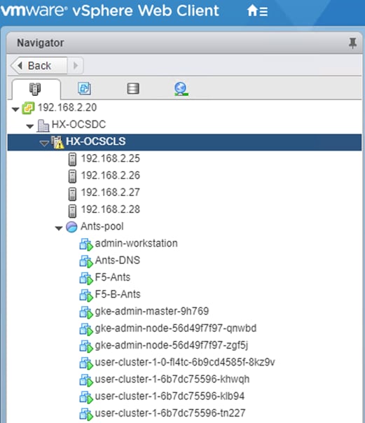
User can now access and execute commands against the user cluster using the kubectl command line tool and the kubeconfig file gets generated by the process (stored in the working directory).
The following command on execution shows the number of worker nodes configured for the user cluster:
ubuntu@admin-workstation:~$ kubectl --kubeconfig user-cluster-1-kubeconfig get nodes
NAME STATUS ROLES AGE VERSION
user1-host2 Ready <none> 62d v1.14.7-gke.24
user1-host3 Ready <none> 65d v1.14.7-gke.24
user1-host4 Ready <none> 64d v1.14.7-gke.24
Deploy Additional User Cluster
With Anthos, organizations can scale their environments to incorporate multiple user clusters and segregate workloads between teams. A single admin cluster can support up to five user clusters, and each user cluster can support up to twenty-five nodes.
To add an additional cluster to the deployment, copy the config.yaml file to a new file “create-user-cluster.yaml”.
Make the following edits to the newly created yaml file:
1. Comment out the sections that refer to the existing admincluster with “#”.
2. In the user cluster section, update the following fields:
a. Update the partition name under the bigip section (only when using F5 BIG IP LB).
b. Update the controlplanvip and ingressvip values under the vip section.
c. Update the clustername value.
d. If the user is using manuallb, then in the usercluster section, make the following changes:
usercluster:
vcenter:
network: "HX-ants-vm-network-603"
ipblockfilepath: "/home/ubuntu/user2-hostconfig.yaml"
manuallbspec:
ingresshttpnodeport: 30244
ingresshttpsnodeport: 30880
controlplanenodeport: 30563
addonsnodeport: 0
#bigip:
#credentials: *bigip-credentials
#partition: "user-cluster-1"
vips:
controlplanevip: "10.65.122.117"
ingressvip: "10.65.122.118"
clustername: "user-cluster-2"
3. Once the create-user-cluster.yaml is ready, run the following command to check the config file again to verify that there are no syntax errors. Since the admin section is removed, the kubeconfig file must be referenced.
![]() The kubeconfig file for admin cluster is named as kubeconfig (found in the working directory) .
The kubeconfig file for admin cluster is named as kubeconfig (found in the working directory) .
$ gkectl check-config -–config create-user-cluster.yaml --kubeconfig kubeconfig
4. If all the checks succeed as expected, user can proceed to deploy this new user cluster referencing the kubeconfig file for the admin cluster.
$ gkectl create cluster --config create-user-cluster.yaml --kubeconfig kubeconfig
5. As with the previous deployment, the process runs for several minutes and can be monitored on screen and in vCenter by watching the resource pool as the VMs populate. When complete, the user should be able to see the new user cluster (four nodes) in vCenter.
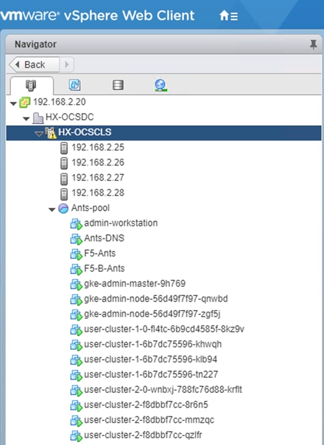
Users can now access and execute commands against the user cluster using the kubectl command line tool and the kubeconfig file gets generated by the process (stored in the working directory).
The execution command below shows the number of worker nodes configured for the user cluster:
ubuntu@admin-workstation:~$ kubectl --kubeconfig user-cluster-2-kubeconfig get nodes
NAME STATUS ROLES AGE VERSION
user-2-worker-1 Ready <none> 64d v1.14.7-gke.24
user-2-worker-2 Ready <none> 64d v1.14.7-gke.24
user-cluster-2 Ready <none> 64d v1.14.7-gke.24
Enabling Ingress for L4 Load Balancer
To enable http ingress on user clusters, follow these steps:
1. On admin workstation create a new self-signed cert and key by running the following command:
ubuntu@admin-workstation:~$ openssl req -nodes -new -x509 -keyout ~/ingress-wildcard.key -out ~/ingress-wildcard.crt -subj "/C=US/ST=CA/L=Sunnyvale/O=On-Prem /OU=GKE/CN=www.gkeonprem.com/emailAddress=dev@gkeonprem.com"
2. Create a Kubernetes secret file with the key and cert that was just generated:
ubuntu@admin-workstation:~$ kubectl --kubeconfig user-cluster-1-kubeconfig create secret tls --namespace gke-system ingressgateway-wildcard-cacerts --cert ingress-wildcard.crt --key ingress-wildcard.key
3. Create and apply the gateway YAML manifest:
ubuntu@admin-workstation:~$ vi gateway.yaml
apiVersion: networking.istio.io/v1alpha3
kind: Gateway
metadata:
name: istio-autogenerated-k8s-ingress
namespace: gke-system
spec:
selector:
istio: ingress-gke-system
servers:
- port:
number: 80
protocol: HTTP2
name: http
hosts:
- "*.gkeonprem.com"
- hosts:
- "*.gkeonprem.com"
port:
name: https-demo-wildcard
number: 443
protocol: HTTPS
tls:
mode: SIMPLE
credentialName: ingressgateway-wildcard-cacerts
4. Apply Kubernetes gateway file on user clusters by running the command:
ubuntu@admin-workstation:~$ kubectl --kubeconfig user-cluster-2-kubeconfig apply -f gateway.yaml
5. Apply Kubernetes gateway file on admin cluster by running the command:
ubuntu@admin-workstation:~$ kubectl --kubeconfig kubeconfig apply -f gateway.yaml
Enabling Access to User Clusters with Google Cloud Console
This section details how to log into the user cluster on the Google Cloud console. After clusters are deployed and registered with Google Cloud, they must be logged into with the Google Cloud console to be managed and to receive additional cluster details. The official procedure to gain access to Anthos user clusters after they are deployed is provided here: https://cloud.google.com/anthos/multicluster-management/console/logging-in
![]() The project and the specific user must be whitelisted to access on-prem clusters in the Google Cloud console and use Anthos GKE on-prem services. If the user is unable to see the clusters after they are deployed, the user need to open a support ticket with Google.
The project and the specific user must be whitelisted to access on-prem clusters in the Google Cloud console and use Anthos GKE on-prem services. If the user is unable to see the clusters after they are deployed, the user need to open a support ticket with Google.
To enable access to the user clusters using the Google console, follow these steps:
1. Create a “node-reader.yaml” file that gives the user the ability to access the cluster.
kind: ClusterRole
apiVersion: rbac.authorization.k8s.io/v1
metadata:
name: node-reader
rules:
- apiGroups: [""]
resources: ["nodes"]
verbs: ["get", "list", "watch"]
2. Apply this file to the cluster that the user wants to log into with the kubectl command.
ubuntu@admin-workstation:~$ kubectl apply -f node-reader.yaml --kubeconfig user-cluster-1-kubeconfig
3. Create a Kubernetes service account (KSA) that the user can use to login. Name this account after the user that uses this account to log into the cluster.
ubuntu@admin-workstation:~$ kubectl create serviceaccount anthoscsi-user --kubeconfig user-cluster-1-kubeconfig
4. Create cluster role-binding resources to bind both the view and newly created node-reader roles to the newly created KSA.
ubuntu@admin-workstation:~$ kubectl create clusterrolebinding anthoscsi-user-view --clusterrole view --serviceaccount default:anthoscsi-user --kubeconfig user-cluster-1-kubeconfig
5. The user can extend the permissions and grant the KSA user a role with cluster admin permissions.
ubuntu@admin-workstation:~$ kubectl create clusterrolebinding anthoscsi-user-admin --clusterrole cluster-admin --serviceaccount default:anthoscsi-user --kubeconfig user-cluster-1-kubeconfig
6. With the KSA account created and assigned with correct permissions, the user can create a bearer token to allow access with the GKE Console. To do so, set a system variable for the secret name, and pass that variable through a kubectl command to generate the token.
ubuntu@admin-workstation:~$ SECRET_NAME=$(kubectl get serviceaccount anthoscsi-user -- kubeconfig user-cluster-1-kubeconfig -o jsonpath='{$.secrets[0].name}')
ubuntu@admin-workstation:~$ kubectl get secret ${SECRET_NAME} --kubeconfig user-cluster-1-kubeconfig -o jsonpath='{$.data.token}' | base64 -d
7. Copy the token. In the Google Cloud console, navigate to Kubernetes Engine > Clusters. Click login against user-cluster-1. A pop-up window appears with authentication options to login. Click the radio button token and paste the token. This will login the user cluster successfully in Google cloud.
8. Repeat steps 1-7 to login additional user clusters into Google Cloud. After the successful login of the first and the second user clusters (assuming there are two clusters in Anthos GKE on-prem deployment), the user can see the clusters logged in as shown below:
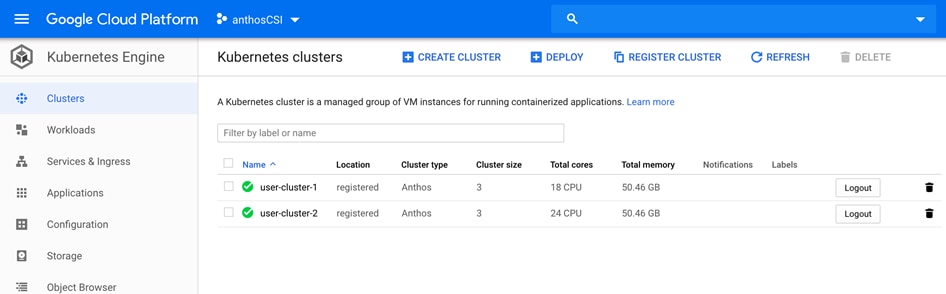
Users can view and manage the user cluster resources and workloads on the Google Cloud console as shown below:

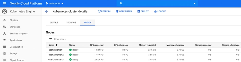
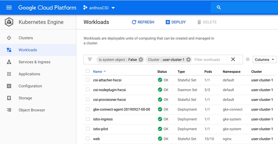
Google Cloud Platform Marketplace
Google Cloud Marketplace lets users to quickly deploy functional software packages that run on Google Cloud Platform. Even if the user is unfamiliar with services like Compute Engine or Cloud Storage, they can easily run a software package without having to manually configure the software, virtual machine instances, storage, or network settings. They can deploy a software package now, and scale that deployment later when user applications require additional capacity. Google Cloud Platform updates the images for these software packages to fix critical issues and vulnerabilities but does not update software that is being already deployed.
In this solution, we chose the Magento application to show the ease with which the application can be deployed using Marketplace on GCP. To select an application from the Market and deploy on Kubernetes Engine, follow these steps:
1. Navigate to Kubernetes Engine > Cluster. Click Marketplace. Choose an application from Marketplace. In this example, Magento is selected.
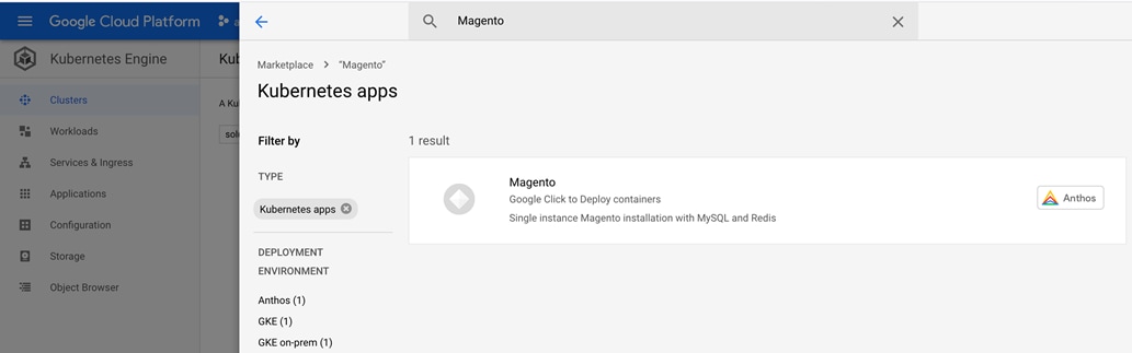
2. Review the application overview and click Configure if the user intends to choose the application.
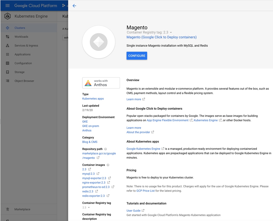
3. The user can edit the configuration as per their requirements and click Deploy.
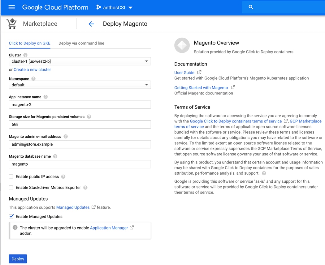
4. When the cluster is deployed successfully, the user can view the new cluster added in the Kubernetes Engine > Clusters.
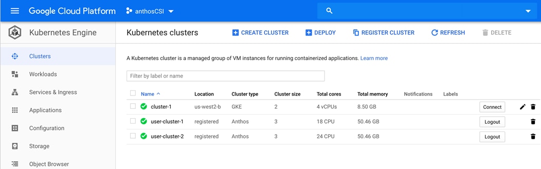
5. The user can monitor the workload in the newly deployed cluster by clicking Kubernetes Engine > Workloads.
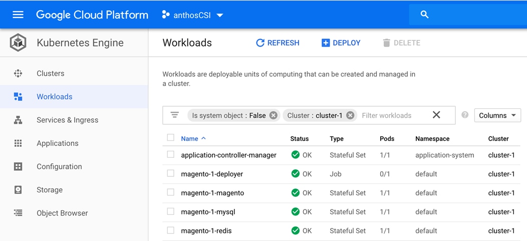
Upgrading Anthos GKE on-prem
To upgrade Anthos GKE on-prem, the user needs to upgrade the admin-workstation and then upgrade the GKE on-prem cluster. For upgrading to the latest available version of GKE on-prem, it is recommended to follow the guidelines at Upgrading Anthos GKE on-prem for undisrupted upgrade of the existing GKE on-prem cluster.
Installing HX-CSI Storage Plugin
This section details how to install the HX-CSI storage plugin. The Container Storage Interface (CSI) is a standard for exposing arbitrary block and file storage systems to containerized workloads on Container Orchestration Systems (COs) like Kubernetes. Using CSI, third-party storage providers can write and deploy plugins exposing new storage systems in Kubernetes without ever having to touch the core Kubernetes code. HX-CSI is Cisco’s storage orchestrator for containers, based on standard CSI implementation. HX-CSI plugin is deployed as containers on Anthos cluster. With HX-CSI, microservices and containerized applications can take advantage of enterprise-class storage services provided by Cisco HyperFlex HCI for persistent storage mounts. Depending on an application’s requirements, HX-CSI dynamically provisions storage for Cisco HyperFlex HCI.
Enabling Kubernetes Integration in Cisco HyperFlex Connect
The user should enable Kubernetes on Cisco HyperFlex via HyperFlex Connect. To enable Kubernetes, follow these steps:
![]() Enabling Kubernetes integration within Cisco HyperFlex Connect will not disrupt any existing workloads running on the HyperFlex cluster
Enabling Kubernetes integration within Cisco HyperFlex Connect will not disrupt any existing workloads running on the HyperFlex cluster
1. Navigate to the Cisco HyperFlex cluster by using a supported web browser (for example, https://<hyperflex_cluster_management_IP_address).
2. In the upper right-hand corner of Cisco HyperFlex Connect, click the Settings menu icon (represented by a Gear icon).
3. From the drop-down list under Integrations, click Kubernetes.
4. On HX Connect, enable Persistent Volumes for Kubernetes by clicking Enable to configure Cisco HyperFlex cluster to support Persistent Volumes for Kubernetes. The default value for a new cluster is Disabled.
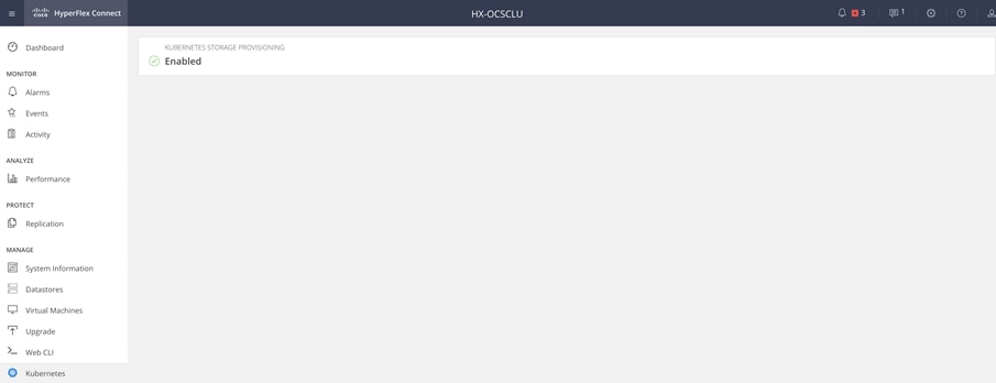
Installing the Cisco HyperFlex CSI Plugin for Kubernetes
To install Cisco HyperFlex CSI plugin, follow these steps:
1. Download Cisco HyperFlex Kubernetes Container Storage Interface (HX-CSI) bundle for Kubernetes persistent volumes “hxcsi-1.0.rel.4.0.418.git.468fb557.tar.gz” at: https://software.cisco.com/download/home/286305544/type/286305994/release/4.0(1b)
2. On the admin-workstation, open and extract the Cisco HyperFlex CSI Bundle.
ubuntu@admin-workstation:~/hxcsi$ tar -xf ./hxcsi-1.0.rel.4.0.418.git.468fb557.tar.gz
ubuntu@admin-workstation:~/hxcsi$ ls -ltr
total 62160
drwxr-xr-x 2 ubuntu ubuntu 4096 Jul 8 2019 setup
drwxr-xr-x 4 ubuntu ubuntu 4096 Jul 8 2019 examples
-rw-r--r-- 1 ubuntu ubuntu 63627674 Dec 21 16:59 hxcsi-1.0.rel.4.0.418.git.468fb557.tar.gz
drwxrwxr-x 2 ubuntu ubuntu 4096 Dec 21 17:00 images
drwxrwxr-x 2 ubuntu ubuntu 4096 Dec 23 16:18 hxcsi-deploy
3. To push the Cisco HyperFlex CSI container image to a locally available container registry, follow these steps:
a. On the admin-workstation, use the docker load --input command to load the Cisco HyperFlex CSI container image from the “images” directory.
ubuntu@admin-workstation:~/hxcsi$ docker load --input ./images/ hxcsi-1.0.rel.4.0.418.git.468fb557.tar
b. Tag the docker image such that it represents the location of the private docker image repository.
ubuntu@admin-workstation:~/hxcsi$ docker tag hxcsi:1.0.rel.4.0.418.git.468fb557 <IP - where private registry is configured>/hxcsi:1.0.rel.4.0.418.git.468fb557
c. On the admin-workstation, run docker push to push the docker image to the private docker image repository.
ubuntu@admin-workstation:~/hxcsi$ docker push <IP - where private registry is configured>/hxcsi:1.0.rel.4.0.418.git.468fb557
d. Once the Cisco HyperFlex CSI container image has been successfully pushed to the private docker image repository, user can delete the local docker image on the admin-workstation using the docker rmi command.
ubuntu@admin-workstation:~/hxcsi$ docker rmi <IP - where private registry is configured>/hxcsi:1.0.rel.4.0.418.git.468fb557
4. In order to deploy the Cisco HyperFlex CSI integration, user must run the hxcsi-setup script. The hxcsi-setup script resides in the “setup” directory and automatically generates the necessary YAML files that then get applied (submitted) to the Kubernetes cluster to deploy the Cisco HyperFlex CSI components. Run the following command to auto generate YAML files for HX-CSI deployment:
ubuntu@admin-workstation:~/hxcsi$ ./setup/hxcsi-setup -cluster-name hxcsi -hx-csi-image <IP - where private registry is configured>/hxcsi:1.0.rel.4.0.418.git.468fb557 -iscsi-url <HX Connect IP> -url <HX Connect IP> -username admin -password <password>
5. After running the hxcsi-setup script and generating the Cisco HyperFlex CSI deployment (YAML) files, a new “hxcsi-deploy” directory will be created. Run kubectl create command to deploy HX-CSI pods on the user clusters (user-cluster-1 and user-cluster-2) of Anthos GKE on-prem deployment as follows.
ubuntu@admin-workstation:~/hxcsi$ kubectl --kubeconfig /home/ubuntu/user-cluster-1-kubeconfig create -f ./hxcsi-deploy/
ubuntu@admin-workstation:~/hxcsi$ kubectl --kubeconfig /home/ubuntu/user-cluster-2-kubeconfig create -f ./hxcsi-deploy/
6. On the admin-workstation, use the kubectl get pods command to verify the HX-CSI components have been deployed and are running.
ubuntu@admin-workstation:~$ kubectl --kubeconfig user-cluster-1-kubeconfig get pods
NAME READY STATUS RESTARTS AGE
csi-attacher-hxcsi-0 2/2 Running 0 65d
csi-nodeplugin-hxcsi-fg5vl 2/2 Running 0 63d
csi-nodeplugin-hxcsi-phfq7 2/2 Running 0 65d
csi-nodeplugin-hxcsi-v52b2 2/2 Running 0 64d
csi-provisioner-hxcsi-0 2/2 Running 0 64d
ubuntu@admin-workstation:~$ kubectl --kubeconfig user-cluster-2-kubeconfig get pods
NAME READY STATUS RESTARTS AGE
csi-attacher-hxcsi-0 2/2 Running 2 65d
csi-nodeplugin-hxcsi-26kfv 2/2 Running 2 65d
csi-nodeplugin-hxcsi-mns64 2/2 Running 2 65d
csi-nodeplugin-hxcsi-mrhnk 2/2 Running 0 65d
csi-provisioner-hxcsi-0 2/2 Running 9 65d
Verifying Cisco HyperFlex CSI Storage Class Creation
Once the components are up and running, the user should create a Storage Class that allows developers/end-users to consume storage through the Cisco HyperFlex CSI integration. To create and verify HX-CSI storage class, follow these steps:
1. On admin-workstation create a YAML file named hxcsi-storage-class.yaml. The YAML should have the following content:
ubuntu@admin-workstation:~$ vi hxcsi-storage-class.yaml
kind: StorageClass
apiVersion: storage.k8s.io/v1
metadata:
name: csi-hxcsi-default
provisioner: csi-hxcsi
parameters:
2. Run the kubectl create -f command to create the Cisco HyperFlex CSI Storage Class on both the user clusters of Anthos GKE on-prem deployment.
ubuntu@admin-workstation:~$ kubectl --kubeconfig user-cluster-1-kubeconfig create -f hxcsi-storage-class.yaml
ubuntu@admin-workstation:~$ kubectl --kubeconfig user-cluster-2-kubeconfig create -f hxcsi-storage-class.yaml
3. On admin-workstation, run the kubectl get sc command to verify the Cisco HyperFlex CSI Storage Class was created.
ubuntu@admin-workstation:~$ kubectl --kubeconfig user-cluster-1-kubeconfig get sc
NAME PROVISIONER AGE
csi-hxcsi-default csi-hxcsi 64d
standard (default) kubernetes.io/vsphere-volume 65d
ubuntu@admin-workstation:~$ kubectl --kubeconfig user-cluster-2-kubeconfig get sc
NAME PROVISIONER AGE
csi-hxcsi-default csi-hxcsi 64d
standard (default) kubernetes.io/vsphere-volume 65d
Installing AppDynamics for Monitoring Anthos GKE on-prem Cluster
In this section we deployed AppDynamics to establish full-scale monitoring of Application and Kubernetes clusters running on GKE. To deploy AppDynamics, follow these steps:
1. Prerequisite – user should have access to AppDynamics SaaS controller (Alternatively, user can sign up to AppDynamics SaaS controller trial account following the link: https://www.appdynamics.com/free-trial/)
2. Install Kubernetes Cluster Agent to monitor Kubernetes Clusters
3. Deploy a sample containerized application along with APM agents on Anthos GKE
a. Validate APM capability
b. Validate end user monitoring capability
c. Measure business performance of the application
The user is assumed to have provisioned the AppDynamics SaaS controller which collects all the metrics from Applications and Kubernetes cluster and provide comprehensive visibility. Users can download the Cluster Agent by logging in to the agent download site: https://download.appdynamics.com.
![]() In this solution we used the SaaS controller located here: https://aws-sandbox.saas.appdynamics.com/controller/
In this solution we used the SaaS controller located here: https://aws-sandbox.saas.appdynamics.com/controller/
Cluster Agent Installation
The Cluster Agent monitors the health of Kubernetes cluster. It can be deployed using the AppDynamics Kubernetes Operator and is supported on all major distributions of Kubernetes, which includes GKE. The Cluster Agent collects metrics and metadata for the entire cluster, each cluster nodes, namespaces and down to the container level. When applications are instrumented with AppDynamics APM agents, the Cluster Agent allows users to view both Kubernetes and APM metrics for those pods, provided that both the Cluster Agent and the APM agents are reporting the data to the same account on the Controller. With the Cluster Agent users can:
· Gain visibility into key Kubernetes metrics and events and detect uptime and availability issues
· Diagnose issues that may prevent uptime or scalability issues such as:
- Pod failures and restarts
- Node starvation
- Pod eviction threats and pod quota violations
- Image and storage failures
- Pending/stuck pods
- Bad endpoints: detects broken links between pods and application components
- Service endpoints in a failed state
- Missing dependencies (Services, configMaps, Secrets)
- Track resource utilization of pods relative to the declared requests and limits.
To view all the cluster metrics that are tracked and captured by default with the AppDynamics Cluster Agent, go to: https://docs.appdynamics.com/display/PRO45/Cluster+Metrics
Prerequisites for Cluster Agent Deployment
Users need to make sure that they have:
· Kubernetes version 1.14
· Anthos GKE on-prem cluster up and running
· Metrics-server deployed
· Access to the Google Anthos admin-workstation
![]() The following steps must be run from the admin-workstation:
The following steps must be run from the admin-workstation:
1. Download the Cluster Agent from https://download.appdynamics.com.
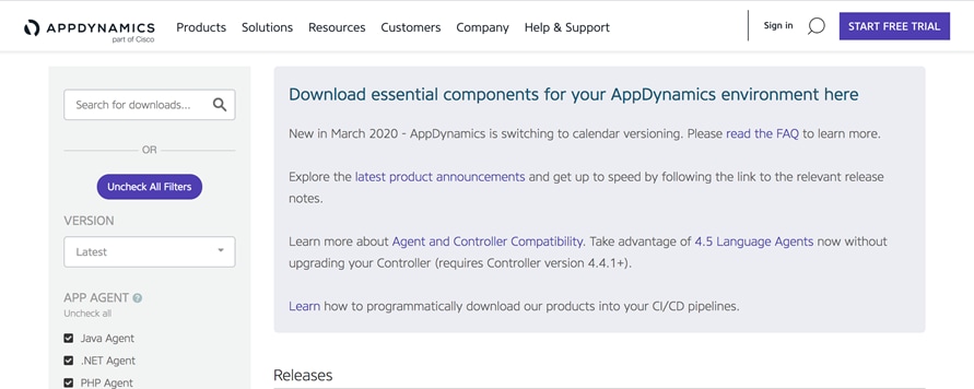
2. The user needs to choose cluster agent with the Linux distribution that fits their requirements. In this solution, we have selected the Ubuntu container.
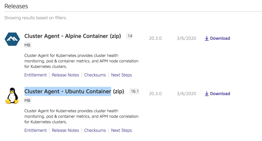
3. Copy the binary to admin-workstation and copy cluster-agent.zip to the home directory in a folder (AppD as name in this solution).
4. Extract all the content from the zip file and check if there are all the content as shown below:
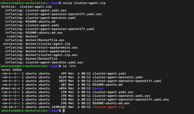
5. Create a new namespace where all the AppDynamics Cluster Agent resources can be run:
ubuntu@admin-workstation:~/AppD$ kubectl -–kubeconfig ~/user-cluster-3-kubeconfig create ns appdynamics
6. Deploy the cluster-agent-operator:
ubuntu@admin-workstation:~/AppD$ kubectl --kubeconfig ~/user-cluster-3-kubeconfig create -f cluster-agent-operator.yaml
Upon execution of the command the following output is generated:
customresourcedefinition.apiextensions.k8s.io/clusteragents.appdynamics.com created
customresourcedefinition.apiextensions.k8s.io/infravizs.appdynamics.com created
customresourcedefinition.apiextensions.k8s.io/adams.appdynamics.com created
serviceaccount/appdynamics-operator created
role.rbac.authorization.k8s.io/appdynamics-operator created
rolebinding.rbac.authorization.k8s.io/appdynamics-operator created
deployment.apps/appdynamics-operator created
serviceaccount/appdynamics-cluster-agent created
clusterrole.rbac.authorization.k8s.io/appdynamics-cluster-agent created
clusterrolebinding.rbac.authorization.k8s.io/appdynamics-cluster-agent created
7. Check if the Operator is running:
ubuntu@admin-workstation:~/AppD$ kubectl --kubeconfig ~/user-cluster-3-kubeconfig get pods -n appdynamics
Expect the following output:

8. Navigate to docker folder. Build the Cluster Agent image, with the files that are located inside the docker folder.
ubuntu@admin-workstation:~/docker$ docker build -t <registryname>/<accountname>/cluster-agent:4.5.16 docker/
9. Push the image to configured private registry. Run docker push <IP - where private registry is configured>/cluster-agent:4.5.16
10. Navigate to back AppD folder and locate the cluster-agent.yaml file.
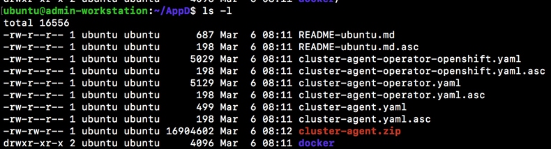
This file keeps the configuration that connect the cluster agent with the controller and report all the metrics.
11. Change the content inside the cluster-agent.yaml. Users have to change the settings to match with their environment (for example, fields like appName, controllerurl, account, image and so on):
![]()
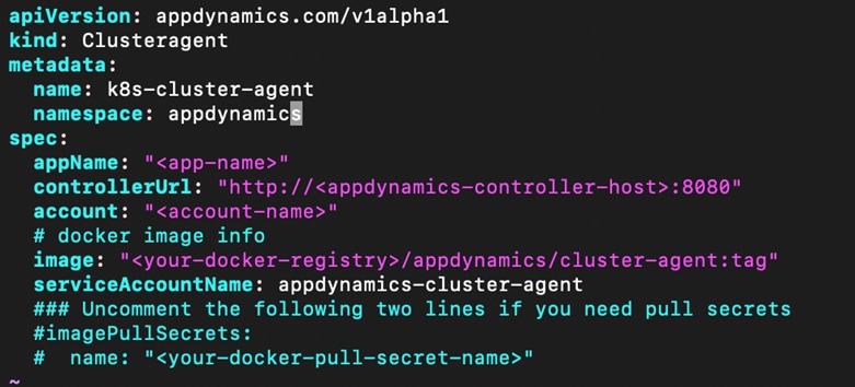
12. If the user’s setup is behind a web proxy, then they need to add the proxy information in the cluster-agent.yaml file. To configure the YAML for proxy environment, see: https://docs.appdynamics.com/display/PRO45/Configure+the+Cluster+Agent#ConfiguretheClusterAgent-ConfigureProxySupport.
13. Create the secret with the AppDynamics controller access key:
kubectl --kubeconfig ~/user-cluster-3-kubeconfig create secret generic cluster-agent-secret --from-literal=controller-key='MY-CONTROLLER-ACCESS-KEY` -n appdynamics
Users can find the “'MY-CONTROLLER-ACCESS-KEY” from the trial controller by navigating as shown in the following screenshots:

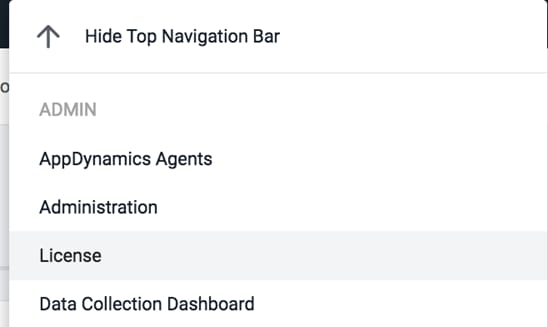
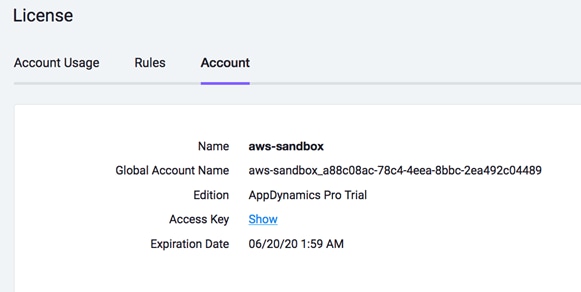
14. Click Show to see and copy the access key to create secret in step 13.
15. Deploy the AppDynamics cluster agent:
ubuntu@admin-workstation:~/AppD$ kubectl --kubeconfig ~/user-cluster-3-kubeconfig create -f cluster-agent.yaml -n appdynamics
16. Check if the cluster agent pod is created:
ubuntu@admin-workstation:~/AppD$ kubectl --kubeconfig ~/user-cluster-3-kubeconfig get pods -n appdynamics

At this stage there has to be two pods running: appdynamics-operator pod and k8s-cluster-agent pod.
Users can see all the metrics related to the cluster and should be able to view the AppDynamics Cluster Agent dashboard.
17. Click Servers, then click Clusters. This screen shows all of the Kubernetes clusters being monitored, along with the Kubernetes version of each cluster.
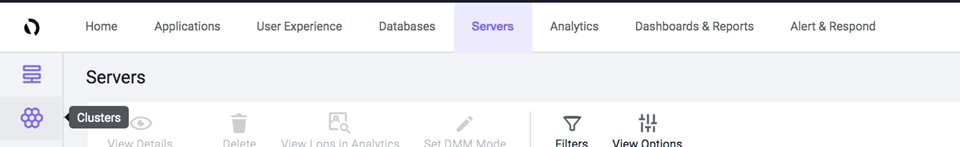
18. Select a cluster and then click Details. This screen presents a high-level view of the health of the Kubernetes cluster, including overall activity and utilization. Additionally, quota information (if quotas are configured) is displayed here.
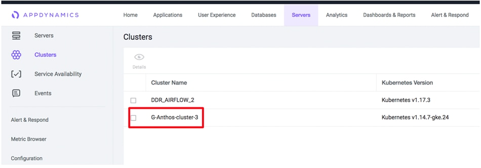
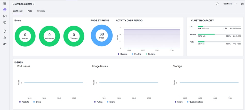
19. Review the details on the screen. Click the Pods tab. This view provides details from an infrastructure perspective. In this screen, users can view the resource utilization and monitor at namespaces level. Any issue related information with the cluster and the state of objects within the cluster can be monitored. Data related to pod status (evicted pods, scaled down pods, resource utilization) can be seen in the pods section as shown in this screenshot:
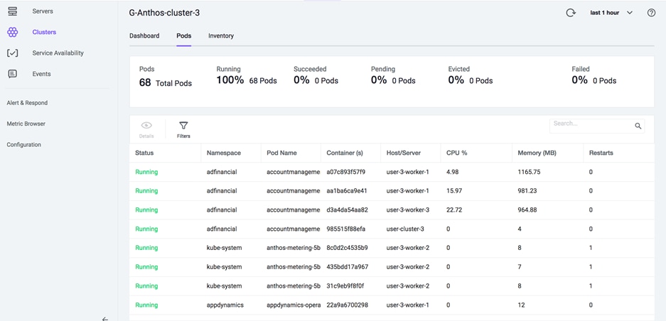
20. Click the Inventory tab to review overall cluster details.
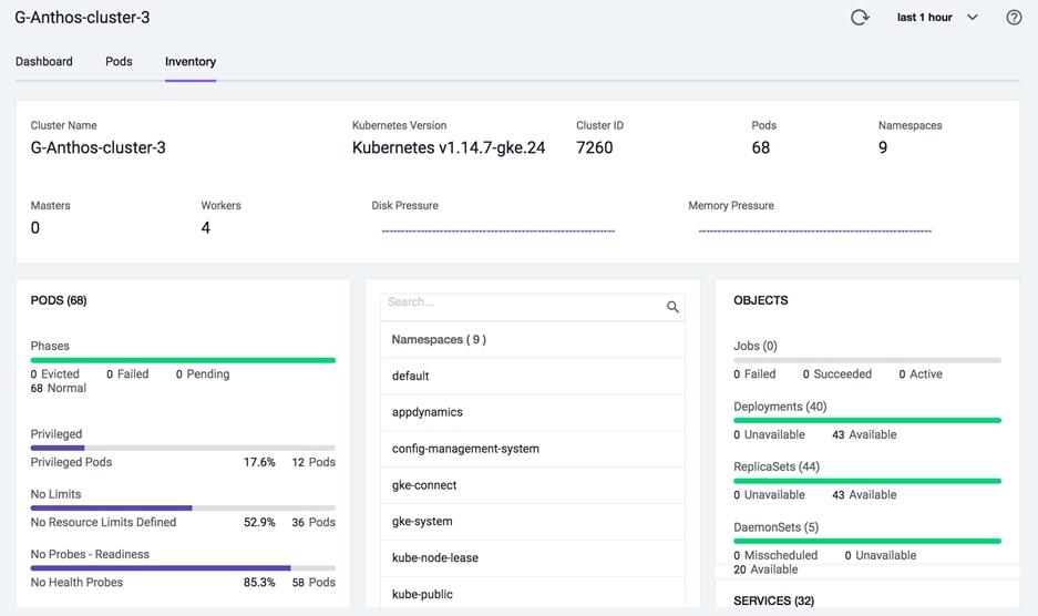
Uninstall Cluster Agent
To uninstall the cluster agent, follow these steps:
1. Delete the ClusterAgent entity.
ubuntu@admin-workstation:~$ kubectl --kubeconfig ~/user-cluster-3-kubeconfig delete -f cluster-agent.yaml -n appdynamics
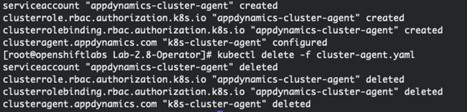
2. Delete the Appdynamics operator.
ubuntu@admin-workstation:~$ kubectl --kubeconfig ~/user-cluster-3-kubeconfig delete -f cluster-agent-operator.yaml -n appdynamics
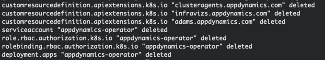
3. Remove the namespace that was used for the AppDynamics resources:
ubuntu@admin-workstation:~$ kubectl --kubeconfig ~/user-cluster-3-kubeconfig delete ns appdynamics
For more information on managing cluster agent (view summary, enable/disable cluster agent, add/delete namespaces and so on), see: https://docs.appdynamics.com/display/PRO45/Use+The+Cluster+Agent
Monitor Demo Application Deployed on Anthos GKE on-prem cluster
As part of this solution, we deployed a demo application on Anthos GKE on-prem cluster. The purpose of this is to showcase a strong value of AppDynamics when it comes to monitoring performance of containerized applications. The application we deployed is packaged with AppDynamics Application Performance Monitoring (APM) agents. Users do not have to perform the installation steps and the agents are also preconfigured. There are many ways in which the AppDynamics microservices agent can be added to a containerized application.
For details about the various approaches, go to: https://www.appdynamics.com/blog/engineering/how-to-instrument-docker-containers-with-appdynamics/.
1. For demonstration purposes, we set the applications under adfinancial namespace in user-cluster-3 deployed. To see all the pods, run:
ubuntu@admin-workstation:~$ kubectl --kubeconfig user-cluster-3-kubeconfig get pods -n adfinancial
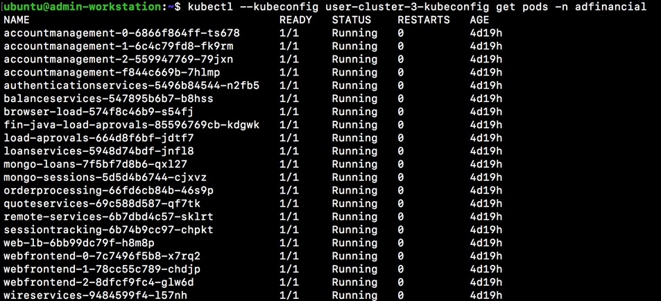
The APM agent is already configured with the application.
2. Log into the AppDynamics controller and find the application AD-Financial-Anthos.
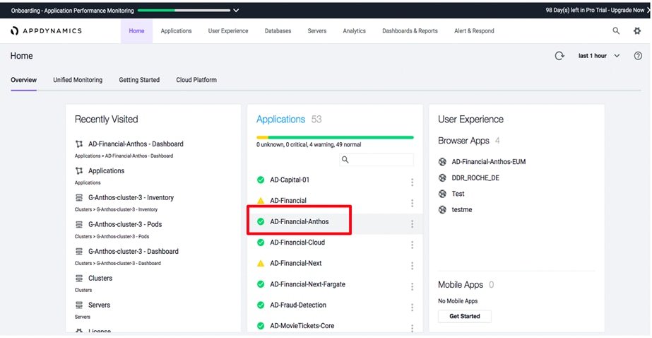
3. Click the application AD-Financial-Anthos as highlighted.
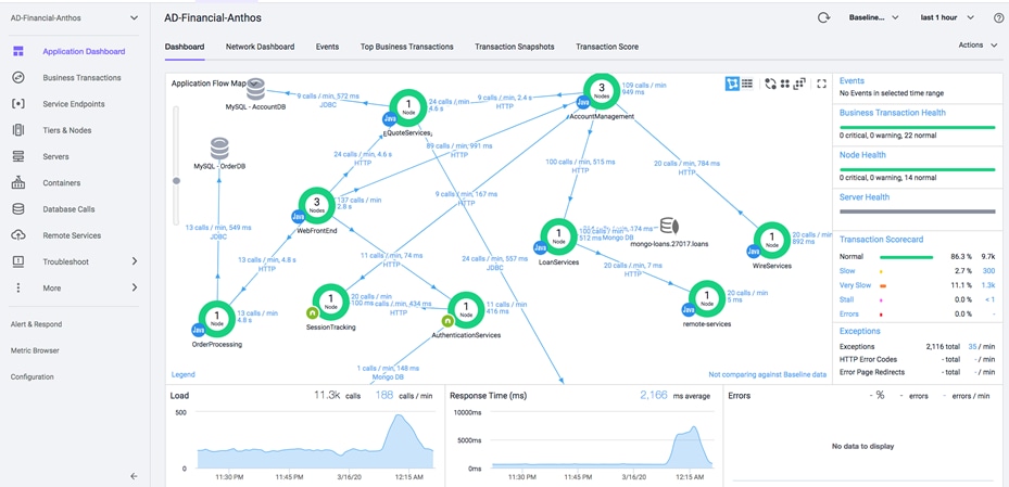
What level of application details can a user drill-down to?
· All the microservices and the dependencies
· Automatically mapped request flow across multiple tier
· Huge fast time to value, maps the application (within 30 minutes)
· Screen can sort by response time, by load, by average response time of all transactions in the application
· Dotted line shows baseline, learned mean of all metrics in the system for every hour of the-day/week/month/year
· Health status based on standard deviations or %age distance from learned baseline can be defined
· Saves difficulty of managing static thresholds (big cost in conventional monitoring, cause of alert storms and false positives)
· Identify anomalies to help users proactively troubleshoot before customers complain about the issues
4. Click the Top Business Transactions as highlighted below:
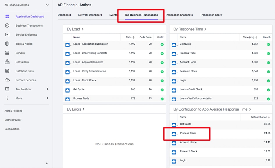
A Business Transaction (BT) is made up of all the required services within the environment that are called upon to fulfill and deliver a response to the user initiated request. These are typically things like login, search, checkout, and so on. Business Transactions reflect the logical way users interact with their applications.
From this view the user can see how BTs can uniquely perform:
1. Click the Process Trade BT as shown in the following screenshot.
![]() By clicking on Process Trade, users can see the details about the Process Trade BT and better understand its performance. The flow described follows the Process Trade transaction. Process Trade follows a different flowmap (though the Process trade flowmap is quite similar to the application flowmap) this helps users in their troubleshooting journey but they need to make sure the prospect is clear about the difference between application and transaction level flowmaps, as this dependency mapping is a valuable AppDynamics feature.
By clicking on Process Trade, users can see the details about the Process Trade BT and better understand its performance. The flow described follows the Process Trade transaction. Process Trade follows a different flowmap (though the Process trade flowmap is quite similar to the application flowmap) this helps users in their troubleshooting journey but they need to make sure the prospect is clear about the difference between application and transaction level flowmaps, as this dependency mapping is a valuable AppDynamics feature.
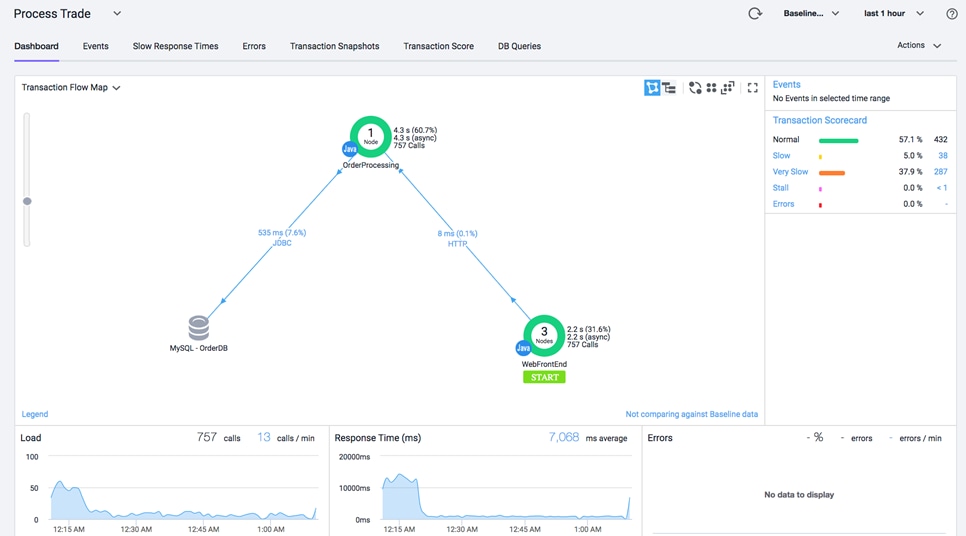
This way users can find all the applications responsible for Process Trade transaction very easily. Also, the transaction scorecard shows that all transactions are classified within normal, slow and very slow categories. Too many transactions classified as slow or very slow automatically enables a “diagnostic session” for the affected transaction and triggers collection of transaction snapshots.
2. For example, users can drill-down on the very slow processes to see the transaction snapshots:
Transaction snapshots provide all the user transactions for Process Trade BT that are being very slow.
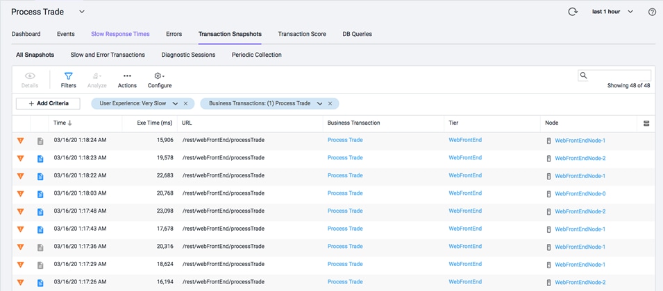
AppDynamics takes transaction snapshots of select instances of a transaction to give the user a cross-tier view of the processing flow for a single invocation of a transaction. AppDynamics monitors every execution of a business transaction in the instrumented environment, and the metrics reflect all such executions. However, for troubleshooting purposes, AppDynamics takes snapshots of specific instances of a transaction. Snapshot mechanism minimizes overhead and maximizes value of data collected, avoiding the cost of collecting lots of “normal” transactions which are of no value for production troubleshooting.
3. Users can choose to see any snapshots based on what they want to troubleshoot.
Transaction snapshots provide information about the transaction and some potential causes of the transaction being slow. To understand and find the root cause, users can further drill-down to view OrderProcessing application.
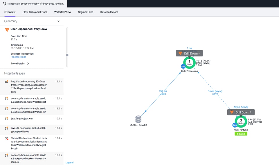
4. Drilling-down to OrderProcessing application provides the view that will help users find the root cause. For example, from the screenshot shown below, users can see that the object is waiting for too long to get the response from the database. This way users can easily and quickly perform root cause analysis on a complex set of applications.
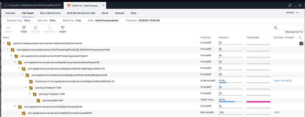
Further database monitoring can also be performed by AppDynamics to monitor queries.
Uninstalling Application
In order to remove the deployed application, the user needs to remove the namespace. All the resources created to this application will be deleted.
ubuntu@admin-workstation:~$ kubectl --kubeconfig user-cluster-3-kubeconfig delete ns adfinancial
This section captures various tests performed on the hardware and software layer of this solution.
Stateful Application Deployment
We chose a combination of applications; Elasticsearch, Kibana and Fluentd to explain the functional testing aspects of application deployment and pvc through the Cisco HX-CSI volume plugin.
Elasticsearch is a real-time, distributed, and scalable search engine. It is commonly used to index and search through large volumes of log data, but can also be used to search many different kinds of documents.
Elasticsearch is commonly deployed alongside Kibana, a powerful data visualization frontend and dashboard for Elasticsearch. Kibana allows user to explore the Elasticsearch log data through a web interface gain insight into deployed Kubernetes applications.
We used Fluentd, a data collector that tails the worker nodes to get container log files, filter and transform the log data, and deliver it to the Elasticsearch cluster, where it will be indexed and stored.
We deployed Elasticsearch, Kibana and Fluentd on Anthos GKE on-prem user-cluster-2. To deploy these applications, follow these steps:
1. Create a namespace on Anthos GKE on-prem user-cluster.
ubuntu@admin-workstation:~$ kubectl --kubeconfig user-cluster-2-kubeconfig create namespace elasticsearch
2. For deploying Elasticsearch application, users need to create a service and the stateful-set. Create elasticsearch_service.yaml and elasticsearch_app.yaml. For Elasticsearch YAML used for the deployment in this solution, see section Appendix – Stateful Application YAML Examples.
3. Deploy the created YAMLs on user-cluster-2 of Anthos GKE on-prem deployment.
ubuntu@admin-workstation:~$ kubectl –-kubeconfig user-cluster-2-kubeconfig create -f elasticsearch_service.yaml
ubuntu@admin-workstation:~$ kubectl –-kubeconfig user-cluster-2-kubeconfig create -f elasticsearch_app.yaml
ubuntu@admin-workstation:~$ kubectl --kubeconfig user-cluster-2-kubeconfig get svc -n elasticsearch
NAME TYPE CLUSTER-IP EXTERNAL-IP PORT(S) AGE
elasticsearch NodePort 10.104.106.167 <none> 9200:30003/TCP,9300:32437/TCP 32d
kibana NodePort 10.98.70.98 <none> 5601:30004/TCP 33d
ubuntu@admin-workstation:~$ kubectl --kubeconfig user-cluster-2-kubeconfig get pods -n elasticsearch
NAME READY STATUS RESTARTS AGE
es-cluster-0 1/1 Running 0 33d
es-cluster-1 1/1 Running 0 33d
es-cluster-2 1/1 Running 0 33d
![]() To create a kibana.yaml to launch Kibana on Kubernetes, we created a Service called kibana and a deployment consisting of one Pod replica. For the Kibana YAML used for the deployment in this solution, see section Appendix – Stateful Application YAML Examples.
To create a kibana.yaml to launch Kibana on Kubernetes, we created a Service called kibana and a deployment consisting of one Pod replica. For the Kibana YAML used for the deployment in this solution, see section Appendix – Stateful Application YAML Examples.
4. Deploy the created YAML on user-cluster-2 of Anthos GKE on-prem deployment.
ubuntu@admin-workstation:~$ kubectl --kubeconfig user-cluster-2-kubeconfig create -f kibana.yaml
ubuntu@admin-workstation:~$ kubectl --kubeconfig user-cluster-2-kubeconfig get pods -n elasticsearch
NAME READY STATUS RESTARTS AGE
es-cluster-0 1/1 Running 0 33d
es-cluster-1 1/1 Running 0 33d
es-cluster-2 1/1 Running 0 33d
kibana-598dc944d9-2jzv6 1/1 Running 0 33d
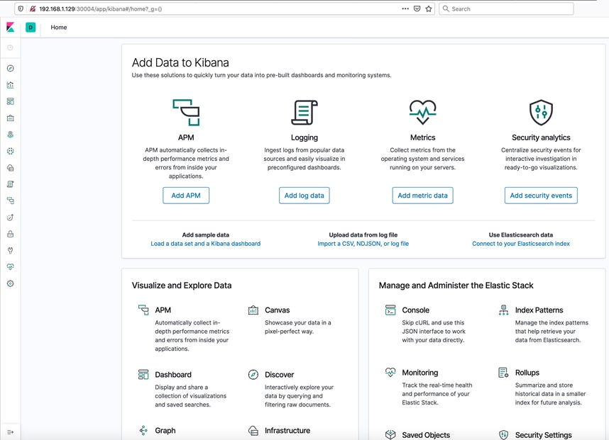
5. Create fluentd.yaml for data collection. For Fluentd YAML used for the deployment in this solution, see section Appendix – Stateful Application YAML Examples.
6. Deploy the created YAML on user-cluster-2 of Anthos GKE on-prem deployment.
ubuntu@admin-workstation:~$ kubectl --kubeconfig user-cluster-2-kubeconfig create -f fluentd.yaml -n elasticsearch
ubuntu@admin-workstation:~$ kubectl --kubeconfig user-cluster-2-kubeconfig get pods -n elasticsearch
NAME READY STATUS RESTARTS AGE
es-cluster-0 1/1 Running 0 33d
es-cluster-1 1/1 Running 0 33d
es-cluster-2 1/1 Running 0 33d
fluentd-9wgpq 1/1 Running 0 33d
fluentd-pphzt 1/1 Running 0 33d
fluentd-sl6n6 1/1 Running 0 33d
kibana-598dc944d9-2jzv6 1/1 Running 0 33d
7. To see if Cisco HX-CSI is the storage class and pv claimed through the application is served by HX-CSI plugin, run:
ubuntu@admin-workstation:~$ kubectl --kubeconfig user-cluster-2-kubeconfig get sc -n elasticsearch
NAME PROVISIONER AGE
csi-hxcsi-default csi-hxcsi 65d
standard (default) kubernetes.io/vsphere-volume 65d
ubuntu@admin-workstation:~$ kubectl --kubeconfig user-cluster-2-kubeconfig get pvc -n elasticsearch
NAME STATUS VOLUME CAPACITY ACCESS MODES STORAGECLASS AGE
data-es-cluster-0 Bound pvc-6e2ee6ba-3cdb-11ea-aebe-4287ca59c224 200Gi RWO csi-hxcsi-default 33d
data-es-cluster-1 Bound pvc-b9890502-3cdb-11ea-aebe-4287ca59c224 200Gi RWO csi-hxcsi-default 33d
data-es-cluster-2 Bound pvc-fef08f67-3cdb-11ea-aebe-4287ca59c224 200Gi RWO csi-hxcsi-default 33d
Users can also view and manage these applications running on user-cluster-2 on GCP as shown in the screenshot below:
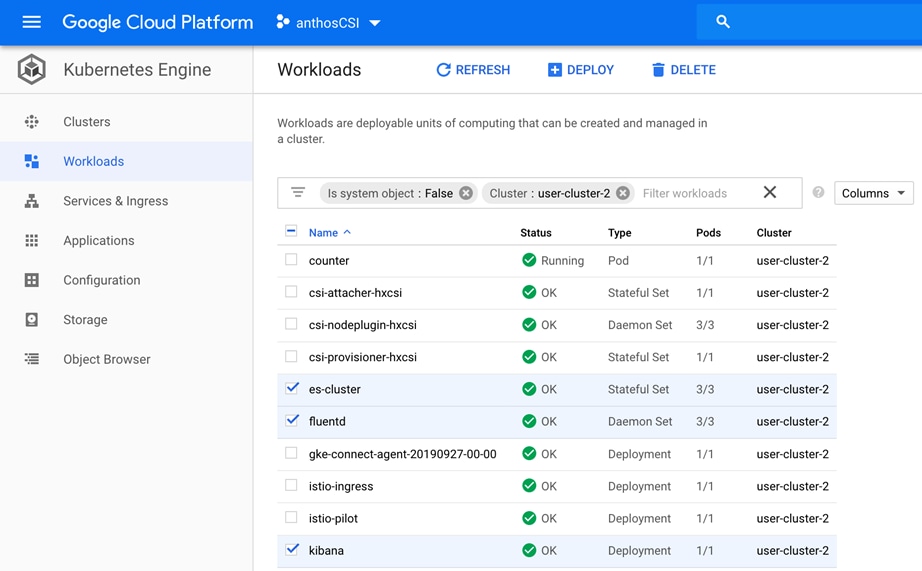
8. Users can monitor the elastic nodes, get logs and different index patterns on Kibana. The following screenshot shows logstash, a wildcard pattern to capture all log data in the elasticsearch cluster.
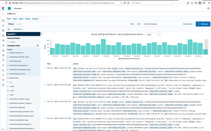
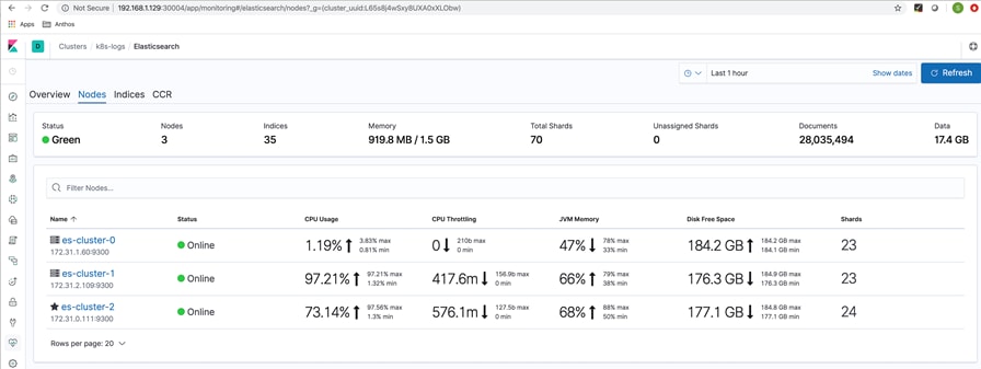
Scale Test
For the application scale test we chose a simple Nginx web application.
We deployed nginx.yaml on Anthos GKE on-prem user-cluster-1. In this YAML, we initially had 10 instances and we scaled the application to 100 (increased the replicas to 100) to test for the smooth PV claim through Cisco HX-CSI volume plugin. We used the following nginx.yaml to run the scale test. For Nginx YAML used for the scale test in this solution, see section Appendix – Stateful Application YAML Examples.
ubuntu@admin-workstation:~$ kubectl --kubeconfig user-cluster-1-kubeconfig create namespace nginx
ubuntu@admin-workstation:~$ kubectl --kubeconfig user-cluster-1-kubeconfig apply -f nginx.yaml -n nginx
Users can view the deployed nginx application from the Google Cloud console. Ten instances of nginx stateful pods running on user-cluster-1 can be seen in the screenshot below:
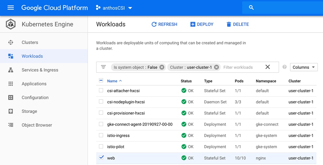
A hundred instances of nginx stateful pods running on user-cluster-1 can be seen in the screenshot below:
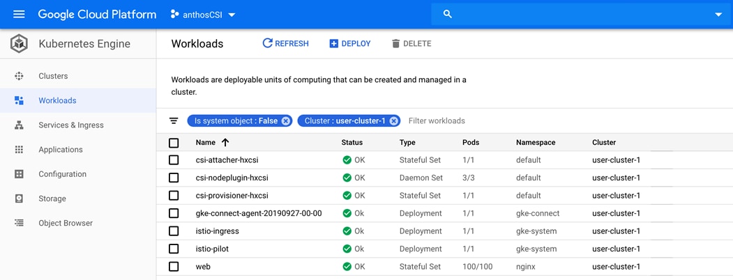
ubuntu@admin-workstation:~$ kubectl --kubeconfig user-cluster-1-kubeconfig get pods -n nginx
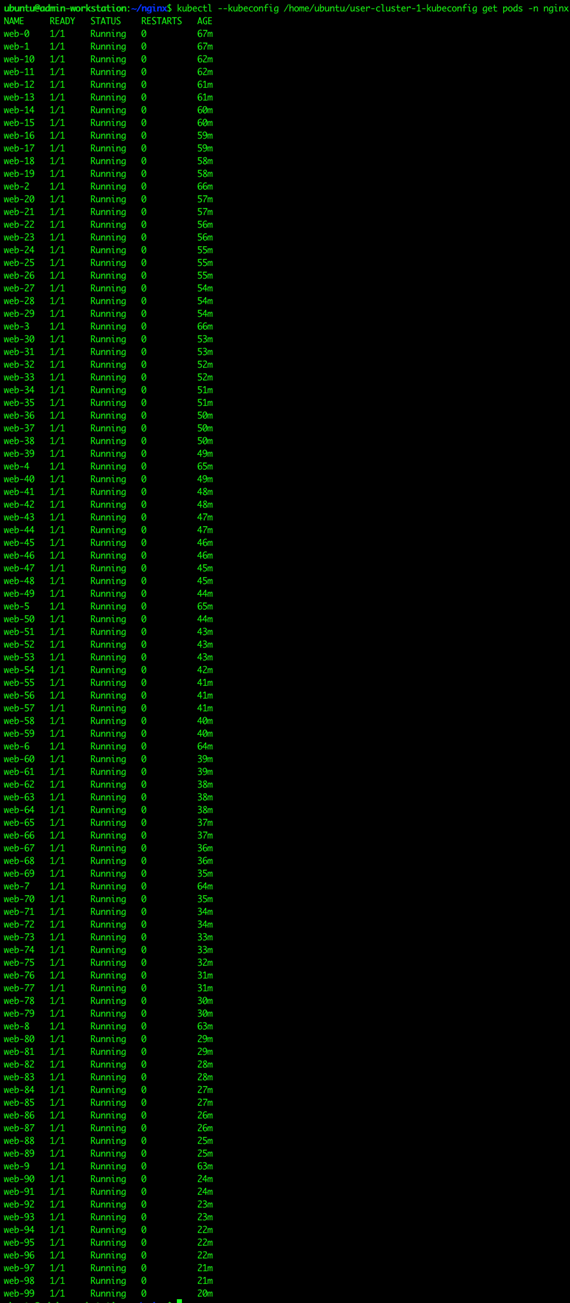
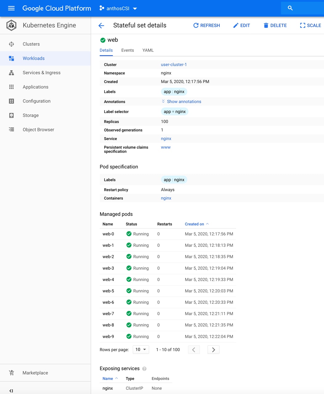
ubuntu@admin-workstation:~$ kubectl --kubeconfig user-cluster-1-kubeconfig get pvc -n nginx
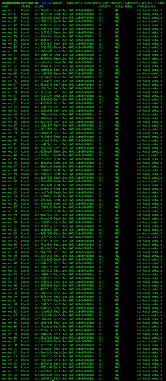
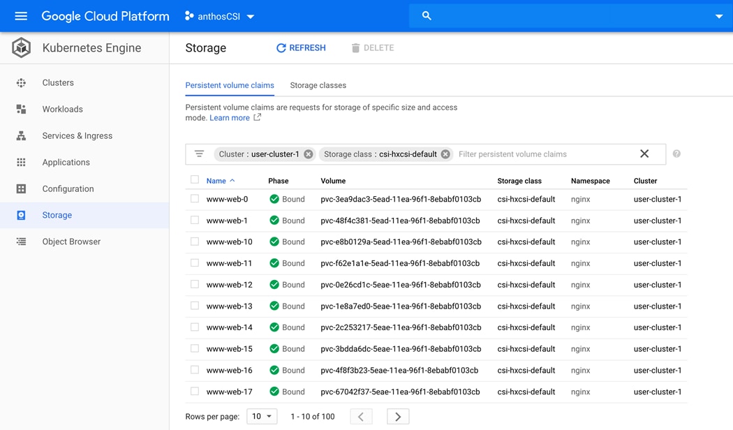
Kubernetes has published the limits for large cluster deployments. Users need to be aware of these limits to plan their large cluster deployments. For the published Kubernetes limits, see: https://kubernetes.io/docs/setup/best-practices/cluster-large/
Also, Kubernetes has certain limitations that users need to be aware of while deploying statefulsets: https://kubernetes.io/docs/concepts/workloads/controllers/statefulset/#deployment-and-scaling-guarantees
High-Availability Test
The hardware and software stack in this solution is highly available. The following hardware and software components were tested for high availability:
· L4 Load Balancer – F5 BIG IP and HAProxy load balancers are configure to work in HA mode.
· Cisco HyperFlex – In Cisco HyperFlex Systems, the data platform spans three or more Cisco HyperFlex HX-Series nodes to create a highly available cluster. Also, the Cisco HX Data Platform provides a highly fault-tolerant distributed storage system that preserves data integrity and optimizes performance for virtual machine (VM) storage workloads. Four Cisco UCS HX240c M5SX servers are used in this solution to create a VMware high availability cluster.
· Cisco UCS Fabric Interconnects – Cisco Fabric interconnects are deployed in pair. They have private static IP address configured. However, they share a virtual IP address and this IP address is always associated with the fabric interconnect running the primary instance of Cisco UCS Manager. The two Cisco UCS Manager instances keep themselves aware of each other by heart-beat message exchanges. When both of the fabric interconnects in cluster are running, the copies of configuration database on them are kept in sync.
· Cisco Nexus 9300 Switches – Cisco Nexus switches are deployed in pair. Cisco NX-OS HA provides physical and software redundancy at every component level, spanning across the physical, environmental, power, and system software aspects of its architecture.
Sizing Considerations for Anthos GKE on Cisco HyperFlex
This section provides resource estimation and sizing perspectives for users to choose the HyperFlex infrastructure that fits for their workloads. As the workload type and user demand vary greatly, these calculations can be used only as a reference for arriving at VM sizing based on the users’ requirements. Appropriate performance testing is suggested before actual implementation to mitigate any resource issues.
![]() Anthos GKE on-prem cluster limits and pod scale limits published by Google: https://cloud.google.com/anthos/gke/docs/on-prem/archive/1.2/quotas.
Anthos GKE on-prem cluster limits and pod scale limits published by Google: https://cloud.google.com/anthos/gke/docs/on-prem/archive/1.2/quotas.
![]() Nodes in the context of Anthos GKE on-prem deployment are vSphere VMs. Follow the VMware performance best practices since VM node properties are not manually modifiable; consider physical NUMA node size when sizing the Kubernetes node.
Nodes in the context of Anthos GKE on-prem deployment are vSphere VMs. Follow the VMware performance best practices since VM node properties are not manually modifiable; consider physical NUMA node size when sizing the Kubernetes node.
Case 1: In this example we show how to estimate the number of pods with pod size of 100 milli cores/1 GB RAM in this sample deployment
We have used Cisco HyperFlex four node HX240c M5SX cluster having mid bin CPU with dual socket (Intel Xeon 6240 CPUs with 18 cores each)/ 192 GB (12 x 16 GB) RAM for Anthos GKE on-prem deployment. When hyperthreading is enabled we get the following:
· Total number of cores: 18 cores x 2 dual socket x 2 hyperthreaded x 4 physical hosts = 288 cores
· Total RAM : 4 x 192 Gb RAM = 768 GB RAM
The compute/memory consumption for each of the control plane entities such as admin workstation, master nodes, and components such as F5 Load balancers and HyperFlex infrastructure controller VMs to be factored in while arriving at available resources for worker nodes where the pods run.
Table 5 provides resource estimation of F5 Load balancer, Anthos and HyperFlex.
| Components |
Resource estimation |
| F5 / HA Proxy load balancer in HA mode |
2x (8 vCPU/16 GB) = 16 vCPU/32 GB RAM
|
| HyperFlex Controller VM (for 4 physical hosts) |
4x (8 vCPU/72 GB RAM) = 32 vCPU/288 GB RAM |
| Anthos admin-workstation |
4 vCPU/8 GB RAM |
| Total vCPU/RAM used for LB + controller VM + admin workstation |
52 vCPU/328 GB RAM |
| Anthos admin master (1 primary + 2 addons) |
3 (4 vCPU/16 GB RAM) = 12 vCPU/48 GB RAM |
| Anthos user masters (assuming two user clusters are deployed) |
2 (4 vCPU/8 GB RAM) = 8 vCPU/16 GB RAM |
| Total CPU/RAM used for LB + controller VM + admin workstation + Total vCPU/RAM including Anthos admin master and 2 user masters |
72 vCPU/392 GB RAM |
Based on the resources allocated to the components in this solution as listed in Table 5, we can assume:
· Worker node VM size as 8 vCPU and 8 GB RAM
· 2 user clusters and
· 20 nodes per user cluster (Anthos 1.2 has a maximum upper limit as 25 worker nodes / user cluster)
Resource requirement for 2 user clusters (20 worker nodes per user cluster): 2 [(20 x 8 vCPU)/ (20 x 8 GB RAM)] = 320 vCPU/320 GB RAM.
The total memory consumed is 392 GB + 320 GB =712 GB, whereas the total available memory is 768 GB.
Total cores consumed by all VMs installed is 320 + 72 = 392 vCPU. Calculating CPU oversubscription results in 392/288 = 1.36, which is reasonable.
There is a max limit of 100 pods per node as mentioned in “Kubernetes for building large clusters” document (https://kubernetes.io/docs/setup/best-practices/cluster-large/) and the same limit applies for Anthos GKE on-prem as well under “Quotas and Limits” (https://cloud.google.com/anthos/gke/docs/on-prem/quotas).
These 2 user clusters will support (20 worker nodes each will allow) 40 x 100 = 4000 pods. If each pod is 100 milli cores and 1GB RAM, it would be restricted to only 320 pods given we do not want to exceed the worker node memory more than 320 GB available.
Case 2: In this example we have arrived at the possible choice of hardware resources for a given number of pods a user wants to run on Anthos GKE on-prem
If a user wants to spin up 500 pods each with 100 milli core CPU and 1 GB RAM, then they would need a total of 50 vCPU and 500 GB RAM. For this requirement we can arrive at the following assumption:
· Consider 20 worker nodes per user cluster (Anthos 1.2 has a maximum user cluster limit of 25 nodes)
· Consider user cluster worker node VM size as 8 vCPU and 8 GB of RAM
With 500 GB RAM (for total possible pods of 500), number of worker nodes required will be 500/8 = 62.5.
62.5 nodes will require 4 user clusters given 20 worker nodes per user cluster limit and since it is a little over 60 nodes for 3 user clusters to accommodate.
For 4 user clusters, resource requirement will be 4 [(20 x 8 vCPU)/(20 x 8 GB RAM)] = 640 vCPU/640 GB RAM. And 4 user masters are required, which will increase the total resources utilized to 80 vCPU and 408 GB RAM refer to Table 5 considering the resource required for other components in the solution.
Total memory requirement will increase to 640 GB + 408 GB = 1048GB RAM (although 500 pods deployment may require only 500 GB + 408 GB = 908 GB RAM). And total vCPU required will increase to 640 + 80 = 720 vCPU.
In order to meet this requirement, a four node HX240c M5SX cluster, Intel Xeon 6258R CPUs (with 28 cores each) and 384 GB (24 x 16 GB) RAM can be considered as this hardware provides:
· Total number of cores: 28 cores x 2 dual socket x 2 hyperthreaded x 4 physical hosts = 448 CPU cores
· Total RAM: 4 x 384 GB RAM = 1536 GB RAM
On the CPU side, there is an oversubscription of 720/448 = 1.6, which is typically considered acceptable; however, it is recommended to run performance tests before deploying the application that the user intends to run.
Powered by Kubernetes and other open-source technologies, Anthos is the only software-based hybrid platform available today that lets users choose and run their applications unmodified on existing on-premises hardware investments or in the public cloud. The Cisco HyperFlex system, a hyperconverged infrastructure, lets users add storage and computing resources in real time, making it the best choice for enterprises to achieve cloud-like scale on-premises with Anthos GKE scale-out capabilities for container runtimes. Anthos simplifies user operations because they can use the same Kubernetes tools on-premises and in the cloud. In addition, users can create their own private registry to maintain application container images between the two environments.
Cisco HyperFlex with Anthos is an enterprise-level hybrid cloud solution that uses best-in-class features of hyperconverged infrastructure with Cisco HX-CSI plugin, and Google Cloud’s Anthos for the deployment of Kubernetes clusters. With Anthos on Cisco HyperFlex, organizations can have access to a simple, high-performing, and scalable architecture to build their hybrid cloud operations, without any of the additional overhead associated with deploying and managing Kubernetes clusters manually. Additionally, Cisco AppDynamics for Anthos on Cisco HyperFlex provides real-time performance monitoring from code level to customer experience to simplify day-to-day operations.
This section provides all the YAML configuration details used for this solution.
Stateful Application Deployment
In the following sections, the YAML examples used for Elastic search, Kibana and Fluentd application deployment are provided.
Elasticsearch YAML Example
ubuntu@admin-workstation:~/stateful-app$ vi elasticsearch_service.yaml
kind: Service
apiVersion: v1
metadata:
name: elasticsearch
namespace: elasticsearch
labels:
app: elasticsearch
spec:
selector:
app: elasticsearch
type: NodePort
ports:
- port: 9200
nodePort: 30003
name: rest
- port: 9300
name: inter-node
ubuntu@admin-workstation:~/stateful-app$ vi elasticsearch_app.yaml
apiVersion: apps/v1
kind: StatefulSet
metadata:
name: es-cluster
namespace: elasticsearch
spec:
serviceName: elasticsearch
replicas: 3
selector:
matchLabels:
app: elasticsearch
template:
metadata:
labels:
app: elasticsearch
spec:
containers:
- name: elasticsearch
image: docker.elastic.co/elasticsearch/elasticsearch:7.2.0
resources:
limits:
cpu: 1000m
requests:
cpu: 100m
ports:
- containerPort: 9200
name: rest
protocol: TCP
- containerPort: 9300
name: inter-node
protocol: TCP
volumeMounts:
- name: data
mountPath: /usr/share/elasticsearch/data
env:
- name: cluster.name
value: k8s-logs
- name: node.name
valueFrom:
fieldRef:
fieldPath: metadata.name
- name: discovery.seed_hosts
value: "es-cluster-0.elasticsearch,es-cluster-1.elasticsearch,es-cluster-2.elasticsearch"
- name: cluster.initial_master_nodes
value: "es-cluster-0,es-cluster-1,es-cluster-2"
- name: ES_JAVA_OPTS
value: "-Xms512m -Xmx512m"
initContainers:
- name: fix-permissions
image: busybox
command: ["sh", "-c", "chown -R 1000:1000 /usr/share/elasticsearch/data"]
securityContext:
privileged: true
volumeMounts:
- name: data
mountPath: /usr/share/elasticsearch/data
- name: increase-vm-max-map
image: busybox
command: ["sysctl", "-w", "vm.max_map_count=262144"]
securityContext:
privileged: true
- name: increase-fd-ulimit
image: busybox
command: ["sh", "-c", "ulimit -n 65536"]
securityContext:
privileged: true
volumeClaimTemplates:
- metadata:
name: data
labels:
app: elasticsearch
spec:
accessModes: [ "ReadWriteOnce" ]
storageClassName: csi-hxcsi-default
resources:
requests:
storage: 200Gi
Kibana YAML Example
ubuntu@admin-workstation:~/stateful-app$ vi kibana.yaml
apiVersion: v1
kind: Service
metadata:
name: kibana
namespace: elasticsearch
labels:
app: kibana
spec:
type: NodePort
ports:
- port: 5601
nodePort: 30004
selector:
app: kibana
---
apiVersion: apps/v1
kind: Deployment
metadata:
name: kibana
namespace: elasticsearch
labels:
app: kibana
spec:
replicas: 1
selector:
matchLabels:
app: kibana
template:
metadata:
labels:
app: kibana
spec:
containers:
- name: kibana
image: docker.elastic.co/kibana/kibana:7.2.0
resources:
limits:
cpu: 1000m
requests:
cpu: 100m
env:
- name: ELASTICSEARCH_URL
value: http://elasticsearch:9200
ports:
- containerPort: 5601
Fluentd YAML Example
ubuntu@admin-workstation:~/stateful-app$ vi fluentd.yaml
apiVersion: v1
kind: ServiceAccount
metadata:
name: fluentd
namespace: elasticsearch
labels:
app: fluentd
---
apiVersion: rbac.authorization.k8s.io/v1
kind: ClusterRole
metadata:
name: fluentd
labels:
app: fluentd
rules:
- apiGroups:
- ""
resources:
- pods
- namespaces
verbs:
- get
- list
- watch
---
kind: ClusterRoleBinding
apiVersion: rbac.authorization.k8s.io/v1
metadata:
name: fluentd
roleRef:
kind: ClusterRole
name: fluentd
apiGroup: rbac.authorization.k8s.io
subjects:
- kind: ServiceAccount
name: fluentd
namespace: elasticsearch
---
apiVersion: apps/v1
kind: DaemonSet
metadata:
name: fluentd
namespace: elasticsearch
labels:
app: fluentd
spec:
selector:
matchLabels:
app: fluentd
template:
metadata:
labels:
app: fluentd
spec:
serviceAccount: fluentd
serviceAccountName: fluentd
tolerations:
- key: node-role.kubernetes.io/master
effect: NoSchedule
containers:
- name: fluentd
image: fluent/fluentd-kubernetes-daemonset:v1.4.2-debian-elasticsearch-1.1
env:
- name: FLUENT_ELASTICSEARCH_HOST
value: "elasticsearch.kube-logging.svc.cluster.local"
- name: FLUENT_ELASTICSEARCH_PORT
value: "9200"
- name: FLUENT_ELASTICSEARCH_SCHEME
value: "http"
- name: FLUENTD_SYSTEMD_CONF
value: disable
resources:
limits:
memory: 512Mi
requests:
cpu: 100m
memory: 200Mi
volumeMounts:
- name: varlog
mountPath: /var/log
- name: varlibdockercontainers
mountPath: /var/lib/docker/containers
readOnly: true
terminationGracePeriodSeconds: 30
volumes:
- name: varlog
hostPath:
path: /var/log
- name: varlibdockercontainers
hostPath:
path: /var/lib/docker/containers
Stateful Application for Scale Test
This section provides the Nginx YAML example used for scaling the application deployment.
Nginx YAML Example
#simple-statefulset.yaml
---
apiVersion: v1
kind: Service
metadata:
name: nginx
labels:
app: nginx
spec:
ports:
- port: 80
name: web
clusterIP: None
selector:
app: nginx
---
apiVersion: apps/v1beta1
kind: StatefulSet
metadata:
name: web
spec:
serviceName: "nginx"
replicas: 10
template:
metadata:
labels:
app: nginx
spec:
containers:
- name: nginx
image: gcr.io/google_containers/nginx-slim:0.8
ports:
- containerPort: 80
name: web
volumeMounts:
- name: www
mountPath: /usr/share/nginx/html
volumeClaimTemplates:
- metadata:
name: www
annotations:
volume.beta.kubernetes.io/storage-class: csi-hxcsi-default
spec:
accessModes: [ "ReadWriteOnce" ]
resources:
requests:
storage: 1Gi
Sindhu Sudhir – TME, Cisco Systems Inc.
Sindhu is a Technical Marketing Engineer working at Cisco in UCS Datacenter Solutions group. She is currently working on software defined architectures with a strong focus on container-based solutions (Docker, Kubernetes, OpenShift, Google Cloud Platform). Her interests include opensource technologies, cloud native solutions and infrastructure automation for Cisco UCS platform.
Paul Mason - Technical Program Manager, Cloud Partner Engineering, Google LLC
Paul has been at Google for two years following four years at Equinix and eight years at Cisco. Paul has focused his career on helping organizations modernize their data centers, first to virtualization and now to hybrid and mutli-cloud. As the data center technologies have evolved, so has Paul’s skillset from Switching and Routing CCIE, to VMware VCP, to Cloud Solution Architect, and now focused on cloud native architectures and Kubernetes.
Subarno Mukherjee – Cloud Solutions Architect, Cisco Systems Inc.
Subarno is an accomplished information technology professional with more than 14 years of incremental experience in consulting, technology evangelism and cloud solution architecture. Subarno Leads the Cloud Solution Architecture team within Cisco's AppDynamics Group. As cloud solutions architect Subarno provides technical leadership, architectural insights and leads pre-sales efforts to grow AppDynamics' cloud business.
Acknowledgements
For their support and contribution to the design, validation, and creation of this Cisco Validated Design, the authors would like to thank:
· Babu Mahadevan, Aniket Patankar, Michael Zimmerman - Cisco Systems Inc.
· Quang Le, Rose Zhu, Matt Tavis - Google LLC