FlashStack for SAP HANA TDI
Available Languages
Bias-Free Language
The documentation set for this product strives to use bias-free language. For the purposes of this documentation set, bias-free is defined as language that does not imply discrimination based on age, disability, gender, racial identity, ethnic identity, sexual orientation, socioeconomic status, and intersectionality. Exceptions may be present in the documentation due to language that is hardcoded in the user interfaces of the product software, language used based on RFP documentation, or language that is used by a referenced third-party product. Learn more about how Cisco is using Inclusive Language.
- US/Canada 800-553-2447
- Worldwide Support Phone Numbers
- All Tools
 Feedback
 Feedback

FlashStack for SAP HANA TDI
Deployment Guide for FlashStack for SAP HANA TDI
Published: November 2020

In partnership with:
![]()
About the Cisco Validated Design Program
The Cisco Validated Design (CVD) program consists of systems and solutions designed, tested, and documented to facilitate faster, more reliable, and more predictable customer deployments. For more information, go to:
http://www.cisco.com/go/designzone.
ALL DESIGNS, SPECIFICATIONS, STATEMENTS, INFORMATION, AND RECOMMENDATIONS (COLLECTIVELY, "DESIGNS") IN THIS MANUAL ARE PRESENTED "AS IS," WITH ALL FAULTS. CISCO AND ITS SUPPLIERS DISCLAIM ALL WARRANTIES, INCLUDING, WITHOUT LIMITATION, THE WARRANTY OF MERCHANTABILITY, FITNESS FOR A PARTICULAR PURPOSE AND NONINFRINGEMENT OR ARISING FROM A COURSE OF DEALING, USAGE, OR TRADE PRACTICE. IN NO EVENT SHALL CISCO OR ITS SUPPLIERS BE LIABLE FOR ANY INDIRECT, SPECIAL, CONSEQUENTIAL, OR INCIDENTAL DAMAGES, INCLUDING, WITHOUT LIMITATION, LOST PROFITS OR LOSS OR DAMAGE TO DATA ARISING OUT OF THE USE OR INABILITY TO USE THE DESIGNS, EVEN IF CISCO OR ITS SUPPLIERS HAVE BEEN ADVISED OF THE POSSIBILITY OF SUCH DAMAGES.
THE DESIGNS ARE SUBJECT TO CHANGE WITHOUT NOTICE. USERS ARE SOLELY RESPONSIBLE FOR THEIR APPLICATION OF THE DESIGNS. THE DESIGNS DO NOT CONSTITUTE THE TECHNICAL OR OTHER PROFESSIONAL ADVICE OF CISCO, ITS SUPPLIERS OR PARTNERS. USERS SHOULD CONSULT THEIR OWN TECHNICAL ADVISORS BEFORE IMPLEMENTING THE DESIGNS. RESULTS MAY VARY DEPENDING ON FACTORS NOT TESTED BY CISCO.
CCDE, CCENT, Cisco Eos, Cisco Lumin, Cisco Nexus, Cisco StadiumVision, Cisco TelePresence, Cisco WebEx, the Cisco logo, DCE, and Welcome to the Human Network are trademarks; Changing the Way We Work, Live, Play, and Learn and Cisco Store are service marks; and Access Registrar, Aironet, AsyncOS, Bringing the Meeting To You, Catalyst, CCDA, CCDP, CCIE, CCIP, CCNA, CCNP, CCSP, CCVP, Cisco, the Cisco Certified Internetwork Expert logo, Cisco IOS, Cisco Press, Cisco Systems, Cisco Systems Capital, the Cisco Systems logo, Cisco Unified Computing System (Cisco UCS), Cisco UCS B-Series Blade Servers, Cisco UCS C-Series Rack Servers, Cisco UCS S-Series Storage Servers, Cisco UCS Manager, Cisco UCS Management Software, Cisco Unified Fabric, Cisco Application Centric Infrastructure, Cisco Nexus 9000 Series, Cisco Nexus 7000 Series. Cisco Prime Data Center Network Manager, Cisco NX-OS Software, Cisco MDS Series, Cisco Unity, Collaboration Without Limitation, EtherFast, EtherSwitch, Event Center, Fast Step, Follow Me Browsing, FormShare, GigaDrive, HomeLink, Internet Quotient, IOS, iPhone, iQuick Study, LightStream, Linksys, MediaTone, MeetingPlace, MeetingPlace Chime Sound, MGX, Networkers, Networking Academy, Network Registrar, PCNow, PIX, PowerPanels, ProConnect, ScriptShare, SenderBase, SMARTnet, Spectrum Expert, StackWise, The Fastest Way to Increase Your Internet Quotient, TransPath, WebEx, and the WebEx logo are registered trademarks of Cisco Systems, Inc. and/or its affiliates in the United States and certain other countries. LDR1.
All other trademarks mentioned in this document or website are the property of their respective owners. The use of the word partner does not imply a partnership relationship between Cisco and any other company. (0809R)
© 2020 Cisco Systems, Inc. All rights reserved.
Contents
Pure Storage FlashArray//X Configuration
Cisco® Validated Designs (CVDs) consists of systems and solutions that are designed, tested, and documented to facilitate and improve customer deployments. These designs incorporate a wide range of technologies and products into a portfolio of solutions that have been developed to address the business needs of customers and to guide them from design to deployment.
This document discusses the deployment requirements and procedures to install and operate SAP HANA Tailored Data Center Integration (TDI) deployments on FlashStack, a converged infrastructure jointly developed by Cisco and Pure Storage. The predesigned FlashStack solution serves as foundation for a variety of workloads and enables efficient architectural designs based on customer requirements.
FlashStack for SAP HANA is a validated approach to deploy Cisco and Pure Storage technologies in an appliance like infrastructure. The reference architecture builds on the Cisco® Unified Computing System™ (Cisco UCS®) platform based on 2nd Generation Intel Xeon Scalable Processors optionally with DDR4 memory modules only or in a mixed memory configuration of DDR4 modules and Intel® Optane™ DC Persistent Memory Modules (DC PMM). The Cisco UCS Servers connect through Cisco switching products to the Pure Storage® FlashArray//X.
This document details the required configuration steps for SAP HANA TDI deployments whether in SAP HANA Scale-Up or Scale-Out configuration running on either Red Hat Enterprise Linux for SAP Solutions or SUSE Linux Enterprise Server for SAP Applications.
Industry trends indicate a vast data center transformation toward shared infrastructure, multi-tenant workload and cloud computing. Business agility requires application agility, so IT teams must provision applications quickly and resources must scale up (and out) as needed.
Cisco and Pure Storage jointly developed FlashStack, which uses best-in-class storage, server, and network components to serve as the foundation for a variety of workloads, enabling efficient architectural designs that can be quickly and confidently deployed. FlashStack converged infrastructure provides the advantage of having the compute, storage, and network stack integrated with the programmability of Cisco UCS and the on-demand growth and expandability of Evergreen storage from Pure Storage. Users experience appliance-level simplicity with cloud-like efficiencies and economics while maintaining their SAP HANA TDI-based re-deployment/re-use options as their landscape evolves.
SAP HANA is SAP SE’s implementation of in-memory database technology. The SAP HANA database combines transactional and analytical SAP workloads and hereby takes advantage of the low-cost main memory (RAM), data-processing capabilities of multicore processors, and faster data access. Cisco UCS servers equipped with the second-generation Intel® Xeon® Scalable processors support mixed Intel® Optane™ DC PM and DDR4 memory configurations which not only significantly increases the maximum supported memory size but the SAP HANA startup time as well.
The Pure Storage FlashArray//X provides out-of-the-box file sharing capabilities without compromise, thus enabling distributed SAP HANA Scale-Out deployments. It enables organizations to consolidate their SAP landscape and run SAP application servers as well as multiple SAP HANA databases hosted on the same infrastructure.
The target audience for this document includes, but is not limited to field consultants, professional services, IT managers, partner engineers, and customers who want to take advantage of an infrastructure built to deliver IT efficiency and enable IT innovation.
This deployment guide provides step by step configuration and implementation guidelines for the FlashStack data center solution for SAP HANA TDI and show case the scalability, manageability, and simplicity of the FlashStack converged infrastructure solution when deploying SAP HANA mission critical applications.
The previous FlashStack reference architecture has been updated with the up-to-date Cisco and Pure Storage hardware and software components:
● Support for the Cisco UCS 4.1(1) unified software release.
● Cisco UCS B-Series M5 Blade Servers with the second-generation Intel® Xeon® Scalable processors and Cisco 1400 Series Virtual Interface Cards (VICs). Holds true for UCSM managed Cisco UCS C220, C240 and C480 M5 Rack Servers as well.
● Validation with Intel® Optane™ Data Center persistent memory modules (DC PMM)
● Cisco UCS 6454 Fabric Interconnects and Cisco UCS 2408 Fabric Extender
● Validation with Nexus® 9300-FX Switches
● Pure Storage FlashArray//X R3 with DirectFlash Modules
● Cisco Intersight Management and Monitoring
![]() Software versions used in this validation reflect the current version at the time of the publication. Review and implement the Cisco suggested release mentioned on the corresponding Cisco UCS Hardware and Software compatibility list at the time of actual implementation.
Software versions used in this validation reflect the current version at the time of the publication. Review and implement the Cisco suggested release mentioned on the corresponding Cisco UCS Hardware and Software compatibility list at the time of actual implementation.
The FlashStack platform, is a flexible and highly modular converged infrastructure solution. It delivers pre-validated storage, networking, and server technologies and scales easily as requirements and demand change. FlashStack is a defined set of hardware and software that serves as an integrated foundation for both virtualized and non-virtualized workloads. Cisco and Pure Storage carefully validated and verified the FlashStack architecture and its many use cases while creating a portfolio of detailed documentation, information, and references to assist customers in transforming their data centers to this shared infrastructure model.
This portfolio includes, but is not limited to, the following items:
● Best practice architectural design
● Implementation and deployment guidelines
● SAP application sizing recommendations
All components are connected and configured according to best practices of both Cisco and Pure Storage and provide the ideal platform to run a variety of enterprise workloads with confidence. FlashStack can scale up for greater performance and capacity (adding compute, network, or storage resources individually as required), or it can scale out for environments that require multiple consistent deployments.
The validated reference architecture follows the FlashStack for SAP HANA TDI design guide and leverages the Pure Storage FlashArray//X, Cisco Nexus 9300 series and Cisco MDS 9100 series as switching elements as well as Cisco 6400 Series Fabric Interconnects for system management. Each of the Cisco or Pure Storage component families shown offer platform and resource options to scale the infrastructure up or down, while supporting the same features and functionality that are required under the configuration and connectivity best practices of FlashStack.
Validation tests confirm the functionality and resilience of the whole solution.
Solution Architecture
FlashStack for SAP HANA TDI provides an end-to-end architecture that demonstrates support for multiple SAP HANA workloads including high availability and secure multi-tenancy. The architecture builds around the Cisco UCS compute and Pure Storage FlashArray//X connected by Cisco MDS Multilayer SAN Switches and is further enabled by Cisco Nexus Switches.
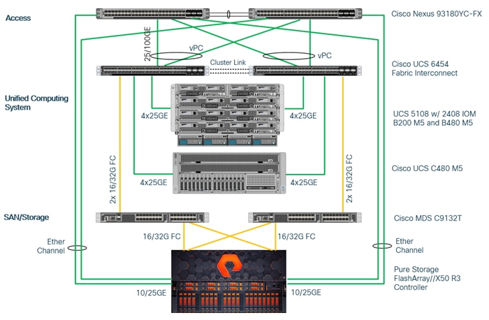
These components form a powerful and scalable design, built on the best practices of Cisco and Pure Storage to create an ideal platform for running a variety of enterprise application workloads. Figure 1 illustrates the topology of the FlashStack solution for SAP HANA TDI.
The Cisco Nexus Switches handle the Ethernet traffic and uplink to the customer network. The chassis with Cisco UCS 2408 FEX leverages 25GE connections to the Fabric Interconnects. The validated design uses 25GE connections from the Fabric Interconnect (FI) to the Cisco Nexus switches and 16 Gb Fibre Channel connections towards the MDS switches and the FlashArray//X.
The FlashStack environment scales easily when requirements and demand change. It is recommended to add additional 4 connections between the Fabric Interconnects and the Cisco Nexus switches and to define a dedicated port channel to handle the SAP HANA backup network traffic explicitly.
Figure 1. High- level Physical Topology of the Validated FlashStack Solution
The information in the deployment guide follows a complete configuration of a customer environment. The installation steps outlined below require various configuration variables which are customer environment and naming convention specific, like host names, IP addresses, VLAN schemes or appropriate MAC addresses. Appendix 1: Configuration Variables, lists the configuration variables used throughout this deployment guide. When completed with the customer-specific site variables it can be used as a reference during the deployment.
The following non-FlashStack system configuration needs to be in place before you start:
● Internal and external DNS records
● Firewall & Proxy configuration
● Active Directory Domain (required for an SAP HANA Scale-Out scenario only)
The lab infrastructure uses a management pod which includes a pair of Cisco Nexus 9000 Switches in standalone mode for out-of-band management network and a pair of Cisco UCS C220 M5 Rack Servers running VMware ESXi. The hypervisor runs a vCenter Server Appliance and VMware hosts provide the Active Domain Service (ADS), Domain Name Service (DNS) and the Network Time Protocol (NTP) Service. Installation and configuration of the management pod and its VMWare hosts are not further detailed in this document but remain pre-requisite to finish the FlashStack installation successfully.
The management pod hosts the Cisco Intersight Virtual Assist Appliance which helps to connect the Pure Storage FlashArray//X to Cisco Intersight.
Cisco UCS Manager
FlashStack configuration with Cisco UCS 6454 Fabric Interconnects, Intel Cascade Lake processors and Intel Optane DC PM modules require Cisco UCS Manager release 4.0(4) or later. Cisco UCS Manager provides unified, embedded management of all Cisco software and hardware components.
The Cisco suggested release based on software quality, stability and longevity is release 4.1(1c). Beginning with Cisco UCS Manager Release 4.1(1), the KVM Console GUI is available as an HTML5-based application only and Java is no longer required to manage and install the environment.
Infrastructure Requirements
SAP defines hardware and software requirements to run SAP HANA TDI systems. This Cisco Validated Design uses guidelines provided by SAP and best practices provided by Cisco and Pure Storage.
SAP HANA 2.0 (TDI) supports servers equipped with Intel Xeon processor E7-8880v3, E7-8890v3, E7-8880v4, E7-8890v4 and all Skylake CPU’s > 8 cores. In addition, the Intel Xeon processor E5-26xx v4 is supported for SAP HANA Scale up deployments.
Appropriate SAP HANA memory sizing must be performed before considering an Intel Optane DC PM based configuration. More detailed information on the configuration and management is available in the whitepaper Cisco UCS for SAP HANA with Intel Optane DC PMM.
SAP HANA supports the following DDR4 only memory configurations:
● Homogenous symmetric assembly of dual in-line memory modules (DIMMs) for example, DIMM size or speed should not be mixed
● Maximum use of all available memory channels
● SAP HANA 2.0 memory per socket ratio is up to 768 GB for SAP NetWeaver Business Warehouse (BW) and DataMart
● SAP HANA 2.0 memory per socket ratio is up to 1536 GB for SAP Business Suite on SAP HANA (SoH) on two or four-socket servers.
Mixed DC PM/DDR4 memory module configurations are supported with SAP HANA 2.0 SPS03 rev 35 and higher:
● Same size of all installed DDR4 memory modules
● Same size of all installed DC PM memory modules
● Homogenous symmetric assembly of all memory modules for example, each memory channel consists of DC PM and DDR4 memory modules.
● Maximum use of all available memory channel.
SAP HANA supports a specific set of CPU and memory combinations only. Table 1 lists the certified Cisco UCS servers for SAP HANA with supported Memory and CPU configuration for different use cases. Mixed memory configurations with DRAM and DC PM modules are available with different memory ratios between (1:1) to (4:1). Table 2 lists the maximum possible memory configuration using Intel Optane DC PMM.
Table 1. Supported DRAM Memory Configuration for FlashStack for SAP HANA TDI
| Cisco UCS Server |
Intel Xeon CPU Socket |
Supported Memory |
Scale-Up / Suite on HANA |
Scale-Out |
| Cisco UCS B200 M5 Cisco UCS C220 M5 Cisco UCS C240 M5 |
2 |
BW: 128 GB to 1.5 TB SoH: 128 GB to 3 TB |
Supported |
Not supported |
| Cisco UCS B480 M5 Cisco UCS C480 M5 |
4 |
BW: 256 GB to 3 TB for BW SoH: 256 GB to 6 TB for SoH |
Supported |
Supported (BW only) |
Table 2. Maximum DRAM/DC PM Memory Configuration for FlashStack for SAP HANA TDI
| Cisco UCS Server |
Intel Xeon CPU Socket |
Max. (4:1) Supported Memory |
Cisco UCS Server |
Intel Xeon CPU Socket |
| Cisco UCS B200 M5 Cisco UCS C220 M5 Cisco UCS C240 M5 |
2 |
BW: 1.5 TB DRAM + 6 TB DC PMM = 7.5 TB SoH: 3 TB DRAM + 12 TB DC PMM = 15 TB |
Supported |
Not supported |
| Cisco UCS B480 M5 Cisco UCS C480 M5 |
4 |
BW: 3 TB DRAM + 12 TB DC PMM = 15 TB SoH: 6 TB DRAM + 24 TB DC PMM = 30 TB |
Supported |
Supported (BW only) |
Network
SAP HANA data center deployments can range from databases running on single hosts (Scale Up), distributed systems (Scale Out) to complex Scale Out systems with multiple hosts located at a primary site having one or more secondary sites to operate SAP HANA with full fault tolerance and disaster recovery.
The different components of the SAP HANA platform communicate via different network channels. To apply the appropriate security and performance measures it is recommended to:
● Separate network communication into logical network zones.
● Enable redundancy for the internal and storage networks, but important too for high availability requirements.
● Separate the Backup network from other HANA related network communication and to configure an additional, exclusive port channel for the Backup network traffic.
Make sure to use the named VLANs to isolate traffic to the external LAN, including broadcast traffic.
Table 3. SAP HANA Network Requirements
| Client Zone |
||||
| Application Server Network |
SAP Application Server to database communication |
All |
Application Server Network |
SAP Application Server to database communication |
| Client Network |
User / Client Application to database communication |
All |
Client Network |
User / Client Application to database communication |
| Data Source Network |
Data import and external data integration |
Optional |
Data Source Network |
Data import and external data integration |
| Internal Zone |
||||
| Inter-Node Network |
Node to node communication |
Scale-Out |
Inter-Node Network |
Node to node communication |
| System Replication Network |
SAP HANA System Replication |
SAP HANA System Replication and Disaster Tolerance |
System Replication Network |
SAP HANA System Replication |
| Storage Zone |
||||
| NFS Shared Network |
Shared SAP HANA binaries |
Scale-Out |
NFS Shared Network |
Shared SAP HANA binaries |
| Backup Network |
Data Backup |
Optional |
Backup Network |
Data Backup |
| Storage Network |
Node to Storage communication |
All |
Storage Network |
Node to Storage communication |
| Infrastructure Related |
||||
| Administration Network |
Infrastructure and SAP HANA administration |
Optional |
Administration Network |
Infrastructure and SAP HANA administration |
| Boot Network |
Boot the Operating Systems via PXE/NFS or iSCSI |
Optional |
Boot Network |
Boot the Operating Systems via PXE/NFS or iSCSI |
The SAP HANA TDI network requirement whitepaper (http://scn.sap.com/docs/DOC-63221) describes more detailed network requirements and recommendations.
Storage
FlashStack provides consolidated access to both SAN storage and Network Attached Storage (NAS) over unified fabric. For SAP HANA Scale Out scenarios the Pure Storage FlashArray//X provides out of the box NFS capabilities to share SAP HANA binaries and maps the Fibre Channel storage LUNs to the SAP HANA server hosts with a point-to-point connection. The SAP HANA Storage Connector (see SAP Note 190823 - SAP HANA Storage Connector API) manages the remapping of the SAP HANA data and log volumes in the event of a failover to the standby host.
The recommended file system sizes (Table 4) for SAP HANA worker nodes depend on the total amount of physical server memory and the given SAP HANA scenario.
Table 4. File System Size Requirements
| Mount Point |
Scale-Up |
Scale-Out |
| / (incl. swap) |
62 GB |
|
| /usr/sap |
50 GB |
|
| /hana/shared |
1 x RAM or 1 TB (whichever is less) |
1 x RAM of a single worker node for each 4 nodes |
| /hana/data/<SID> |
1 x RAM |
|
| /hana/log/<SID> |
If the server memory is <= 512 GB then ½ x RAM If the server memory is > 512 GB then 512 GB |
|
All relevant information about storage requirements is documented in this white paper: https://www.sap.com/documents/2015/03/74cdb554-5a7c-0010-82c7-eda71af511fa.html.
Operating System
The operating systems to operate SAP HANA compatible with Intel Optane DC PM are:
● SUSE Linux Enterprise Server for SAP Applications 12 SP4 or later and 15 or later
● Red Hat Enterprise Linux for SAP Solutions 7.6 or later and 8.0 or later
Review SAP note 2235581 - SAP HANA: Supported Operating Systems to evaluate compatibility information between Linux operating system release and SAP HANA platform releases.
Figure 2 shows the cabling topology for IP network configuration of FlashStack for SAP HANA.
Figure 2. FlashStack Network Device Cabling Topology
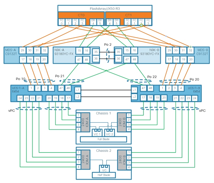
The following tables include both, local and remote device port locations for easier reference. The tables capture the out-of-band management port connectivity into a pre-existing management infrastructure too.
Table 5. Cisco Nexus-A 93180YC-FX Device Cabling
| Local Device |
Local Port |
Connection |
Remote Device |
Remote Port |
| Nexus 93180YC-FX-A |
Eth 1/47 |
25GbE |
Cisco UCS FI-A |
Eth 1/47 |
| Eth 1/48 |
25GbE |
Cisco UCS FI-B |
Eth 1/47 |
|
| Eth 1/53 |
40GbE |
Cisco N9K-Mgmt-A |
Eth 1/49 |
|
| Eth 1/54 |
40GbE |
Cisco N9K-Mgmt-B |
Eth 1/49 |
|
| Eth 1/15 |
10/25GbE |
Pure Storage FlashArray//X CT0 |
Eth 4 |
|
| Eth 1/16 |
10/25GbE |
Pure Storage FlashArray//X CT1 |
Eth 4 |
|
| Eth 1/35 |
10GbE |
Cisco N9K-B (peer-link) |
Eth 1/35 |
|
| Eth 1/36 |
10GbE |
Cisco N9K-B (peer-link) |
Eth 1/36 |
|
| MGMT |
1GbE |
Customer’s Management Switch |
Eth 1/23 |
Table 6. Cisco Nexus-B 93180YC-FX Device Cabling
| Local Device |
Local Port |
Connection |
Remote Device |
Remote Port |
| Nexus 93180YC-FX-B |
Eth 1/47 |
25GbE |
Cisco UCS FI-A |
Eth 1/48 |
| Eth 1/48 |
25GbE |
Cisco UCS FI-B |
Eth 1/48 |
|
| Eth 1/9 |
40GbE |
Cisco N9K-Mgmt-A |
Eth 1/50 |
|
| Eth 1/11 |
40GbE |
Cisco N9K-Mgmt-B |
Eth 1/50 |
|
| Eth 1/15 |
10/25GbE |
Pure Storage FlashArray//X CT0 |
Eth 5 |
|
| Eth 1/16 |
10/25GbE |
Pure Storage FlashArray//X CT1 |
Eth 5 |
|
| Eth 1/35 |
10GbE |
Cisco N9K-B (peer-link) |
Eth 1/35 |
|
| Eth 1/36 |
10GbE |
Cisco N9K-B (peer-link) |
Eth 1/36 |
|
| MGMT |
1GbE |
Customer’s Management Switch |
Any |
![]() Use Twinax cables for the iSCSI port ethernet connectivity from the FlashArray//X to the Nx93180YC-FX to provide the HANA shared filesystem access.
Use Twinax cables for the iSCSI port ethernet connectivity from the FlashArray//X to the Nx93180YC-FX to provide the HANA shared filesystem access.
Table 7. Cisco UCS Fabric Interconnect A Device Cabling
| Local Device |
Local Port |
Connection |
Remote Device |
Remote Port |
| Cisco 6454 Fabric Inter-connect A |
fc 1/1 |
FC uplink |
Cisco MDS-A 9148T |
fc 1/17 |
| fc 1/2 |
FC uplink |
fc 1/18 |
||
| fc 1/3 |
FC uplink |
fc 1/19 |
||
| fc 1/4 |
FC uplink |
fc 1/20 |
||
| Eth 1/17 |
25GbE |
Cisco UCS 5108 - IOM-A 2408 |
1/1 |
|
| Eth 1/18 |
25GbE |
1/2 |
||
| Eth 1/19 |
25GbE |
1/3 |
||
| Eth 1/20 |
25GbE |
1/4 |
||
| Eth 1/47 |
25GbE |
Cisco Nexus 93180YC-FX-A |
Eth 1/47 |
|
| Eth 1/48 |
25GbE |
Cisco Nexus 93180YC-FX-B |
Eth 1/47 |
|
| L1 |
GbE |
Cisco UCS FI-B |
L1 |
|
| L2 |
GbE |
Cisco UCS FI-B |
L2 |
|
| MGMT |
1GbE |
Customer’s Management Switch |
Any |
Table 8. Cisco UCS Fabric Interconnect B Device Cabling
| Local Device |
Local Port |
Connection |
Remote Device |
Remote Port |
| Cisco Fabric Interconnect B |
fc 1/1 |
FC uplink |
Cisco MDS-B 9148T
|
fc 1/17 |
| fc 1/2 |
FC uplink |
fc 1/18 |
||
| fc 1/3 |
FC uplink |
fc 1/19 |
||
| fc 1/4 |
FC uplink |
fc 1/20 |
||
| Eth 1/17 |
40GbE |
Cisco UCS 5108 - IOM-B 2408 |
2/1 |
|
| Eth 1/18 |
40GbE |
2/2 |
||
| Eth 1/19 |
10GbE |
2/3 |
||
| Eth 1/20 |
10GbE |
2/4 |
||
| Eth 1/47 |
25GbE |
Cisco Nexus 93180YC-FX-A |
Eth 1/48 |
|
| Eth 1/48 |
25GbE |
Cisco Nexus 93180YC-FX-B |
Eth 1/48 |
|
| L1 |
GbE |
Cisco UCS FI-A |
L1 |
|
| L2 |
GbE |
Cisco UCS FI-A |
L2 |
|
| MGMT |
1GbE |
Customer’s Management Switch |
Any |
Table 9. Cisco MDS-A 9148T Device Cabling
| Local Device |
Local Port |
Connection |
Remote Device |
Remote Port |
| MDS-A 9148T |
fc 1/17 |
32GbE |
Cisco UCS FI-A |
fc 1/1 |
| fc 1/18 |
32GbE |
fc 1/2 |
||
| fc 1/19 |
32GbE |
fc 1/3 |
||
| fc 1/20 |
32GbE |
fc 1/4 |
||
| fc 1/29 |
16/32GbE |
Pure Storage FlashArray//X CT0 |
CT0.FC0 |
|
| fc 1/30 |
16/32GbE |
Pure Storage FlashArray//X CT1 |
CT1.FC0 |
|
| fc 1/31 |
16/32GbE |
Pure Storage FlashArray//X CT0 |
CT0.FC2 |
|
| fc 1/32 |
16/32GbE |
Pure Storage FlashArray//X CT1 |
CT1.FC2 |
|
| MGMT |
1GbE |
Customer’s Management Switch |
Any |
Table 10. Cisco MDS-B 9148T Device Cabling
| Local Device |
Local Port |
Connection |
Remote Device |
Remote Port |
| MDS-B 9148T |
fc 1/17 |
32GbE |
Cisco UCS FI-A |
fc 1/1 |
| fc 1/18 |
32GbE |
fc 1/2 |
||
| fc 1/19 |
32GbE |
fc 1/3 |
||
| fc 1/20 |
32GbE |
fc 1/4 |
||
| fc 1/29 |
16/32GbE |
Pure Storage FlashArray//X CT0 |
CT0.FC0 |
|
| fc 1/30 |
16/32GbE |
Pure Storage FlashArray//X CT1 |
CT1.FC0 |
|
| fc 1/31 |
16/32GbE |
Pure Storage FlashArray//X CT0 |
CT0.FC2 |
|
| fc 1/32 |
16/32GbE |
Pure Storage FlashArray//X CT1 |
CT1.FC2 |
|
| MGMT |
1GbE |
Customer’s Management Switch |
Any |
Table 11. Pure Storage FlashArray//X 50 R3 Device Cabling
| Local Device |
Local Port |
Connection |
Remote Device |
Remote Port |
| FlashArray//X 50 R3 |
CT0.FC0 |
16/32GbE |
Cisco MDS-A 9148T
|
fc 1/29 |
| CT1.FC0 |
16/32GbE |
fc 1/30 |
||
| CT0.FC2 |
16/32GbE |
fc 1/31 |
||
| CT1.FC2 |
16/32GbE |
fc 1/32 |
||
| CT0.FC1 |
16/32GbE |
Cisco MDS-B 9148T
|
fc 1/29 |
|
| CT1.FC1 |
16/32GbE |
fc 1/30 |
||
| CT0.FC3 |
16/32GbE |
fc 1/31 |
||
| CT1.FC3 |
16/32GbE |
fc 1/32 |
||
| CT0 eth4 |
10/25GbE |
Nexus 93180YC-FX-A |
Eth 1/15 |
|
| CT0 eth5 |
10/25GbE |
Nexus 93180YC-FX-B |
Eth 1/15 |
|
| CT1 eth4 |
10/25GbE |
Nexus 93180YC-FX-A |
Eth 1/16 |
|
| CT1 eth5 |
10/25GbE |
Nexus 93180YC-FX-B |
Eth 1/16 |
Solution components and Software Revisions
The following tables list the components and software revisions validated for the FlashStack for SAP HANA TDI deployment.
Table 12. Inventory and Bill of Material of the Validation Setup
| Vendor |
Name |
Version/Model |
Description |
Quantity |
| Cisco |
Cisco Nexus 93180YC Switch |
N9K-C93180YC-FX |
Cisco Nexus 9300 Series Switches |
2 |
| Cisco |
Cisco MDS 9148T 32GB Multilayer Switch |
DS-C9148T-K9 |
Cisco MDS 9100 Series Multilayer Fabric Switches |
2 |
| Cisco |
Cisco UCS 6454 Fabric Interconnect |
UCS-FI-6454 |
Cisco 6400 Series Fabric Interconnects |
2 |
| Cisco |
Cisco UCS Fabric Extender |
UCS-IOM-2408 |
Cisco UCS 2408 I/O Module (8x 25GB External, 32x 10GB Internal) |
4 |
| Cisco |
Cisco UCS B480 M5 blade servers |
UCSB-B480-M5 |
Cisco UCS B-Series Blade Servers |
4 |
| Cisco |
Cisco UCS VIC 1440 mLom |
UCSB-MLOM-40G-04 |
Cisco UCS VIC 1400 PCIE adapters for blade servers |
4 |
| Cisco |
Cisco UCS VIC 1480 |
UCSB-VIC-M84-4P |
Cisco UCS VIC 1400 PCIE adapters for blade servers |
4 |
| Pure Storage |
FlashArray//X |
FlashArray//X50 R3 |
Pure Storage FlashArray//X |
1 |
Table 13. Hardware and Software Component Versions of the Validated Setup
| Vendor |
Product |
Version |
| Cisco |
Cisco UCSM |
4.1(1c) |
| Cisco |
Cisco UCS 6454 |
7.0(3)N2(4.11b) |
| Cisco |
Cisco UCS B-Series M5 Servers |
4.1(1c) |
| Cisco |
Cisco Nexus 93180YC Switches |
9.2(1) |
| Cisco |
Cisco MDS 9148T 32GB |
8.3(1) |
| Pure Storage |
Purity//FA |
5.3.8 |
| SUSE |
SUSE Linux Enterprise Server for SAP Applications |
15 SP1 |
| RHEL |
Red Hat Enterprise Linux for SAP Solutions |
8.1 |
Performance
The solution is designed to meet SAP HANA TDI performance requirements defined by SAP SE. All data traffic between SAP HANA nodes is handled by the UCS Fabric Interconnect. Each HANA Server is equipped with a minimum of 4 x 10GbE capable Cisco Virtual Interface Card, the storage network provides dedicated bandwidth between SAP HANA servers and the FlashArray//X. For HANA node-to-node network, 10 GB dedicated network bandwidth is provided with non-blocking mode.
All FlashStack components are capable to operate end-to-end with 32GB Fibre channel and meet the SAP HANA TDI performance requirements already with 16GB Fibre channel connectivity.
Cisco Hardware Configuration
Some hardware components like the Cisco UCS Fabric Interconnects or Cisco UCS B-Series blade servers are configured similarly. This document details steps for provisioning multiple Cisco UCS hosts which are identified sequentially, like:
HANA-Server0{1 | 2}.
Angle brackets (<>) indicate a character string that the user needs to enter like a variable pertinent to the customer environment or a password.
Cisco Nexus 9000 Series Switch Network Configuration
This section provides a detailed procedure to configure the Cisco Nexus 9000 Switches part of the FlashStack environment. The configuration steps are based on above cabling plan. If systems are connected on different ports, configure the switches accordingly following the guidelines described in this section.
Ensure the physical hardware installation and cabling is complete before you continue. First create a local management connection through a console terminal to perform the initial configuration and to configure a switch IP address. Second configure the required features and virtual local area networks (VLANs) according to the device cabling documentation.
![]() Connect to the serial or console port of the Nexus switch. The NX-OS setup will automatically start and attempt to enter power on auto provisioning after initial boot.
Connect to the serial or console port of the Nexus switch. The NX-OS setup will automatically start and attempt to enter power on auto provisioning after initial boot.
Cisco Nexus Initial Configuration
To perform the initial Cisco Nexus switch configuration, follow these steps. Keep all settings on default if not listed otherwise.
1. Connect to the Nexus A console port and press the spacebar:
● Would you like to enter the basic configuration dialog (yes/no): yes
● Enter the switch name : <var_nexus_A_hostname>
● Continue with Out-of-band (mgmt0) management configuration? (yes/no) [y]:
● Mgmt0 IPv4 address : <var_nexus_A_mgmt0_ip>
● Out of Band Mgmt0 IPv4 netmask : <var_oob_vlan_net>
● Configure the default gateway? (yes/no) [y]:
● IPv4 address of the default gateway : <var_oob_vlan_gw>
● Number of rsa key bits <1024-2048> [2048]: 1024
● Configure the ntp server? (yes/no) [n]: y
● NTP server IPv4 address : <var_global_ntp_server_ip>
2. The configuration wizard lists a configuration summary at the end. Review the summary and save it.
3. Connect to the Nexus B console port and press the spacebar:
● Would you like to enter the basic configuration dialog (yes/no): yes
● Enter the switch name : <var_nexus_B_hostname>
● Continue with Out-of-band (mgmt0) management configuration? (yes/no) [y]:
● Mgmt0 IPv4 address : <var_nexus_B_mgmt0_ip>
● Out of Band Mgmt0 IPv4 netmask : <var_oob_vlan_net>
● Configure the default gateway? (yes/no) [y]:
● IPv4 address of the default gateway : <var_oob_vlan_gw>
● Number of rsa key bits <1024-2048> [2048]: 1024
● Configure the ntp server? (yes/no) [n]: y
● NTP server IPv4 address : <var_global_ntp_server_ip>
4. The configuration wizard lists a configuration summary at the end. Review the summary and save it.
Enable Cisco Nexus 9000 Series Switch Features and Spanning-Tree
To enable the required features and set the default spanning tree behavior on both Nexus switches, run the following commands:
1. Run the following:
N9K-A|B# config terminal
2. Enable features:
N9K-A|B(config)# feature udld
N9K-A|B(config)# feature lacp
N9K-A|B(config)# feature vpc
N9K-A|B(config)# feature interface-vlan
N9K-A|B(config)# feature lldp
3. Set Spanning-Tree:
N9K-A|B(config)# spanning-tree port type network default
N9K-A|B(config)# spanning-tree port type edge bpduguard default
N9K-A|B(config)# spanning-tree port type edge bpdufilter default
4. Persist the configuration:
N9K-A|B(config)# copy run start
Create VLANs for SAP HANA Traffic
Separate network traffic using multiple VLANs for SAP Hana traffic. In Nexus configuration mode create VLANs depending on customer and HANA scenario requirements:
5. Use multiple VLANs for network traffic separation. Run the following commands in the Nexus configuration mode to create the VLANs:
N9K-A|B(config)# vlan <var_oob_vlan_id>
N9K-A|B(config-vlan)# name HANA-Node-Mgmt
N9K-A|B(config-vlan)# exit
6. Create additional VLANs using the same command syntax as shown above:
vlan <var_client_vlan_id> name HANA-Client
vlan <var_AppServer_vlan_id> name HANA-AppServer
vlan <var_datasource_vlan_id> name HANA-DataSource
vlan <var_backup_vlan_id> name HANA-Node-Backup>
7. Other SAP HANA scenarios like Scale-Out or SAP HANA System Replication can require additional VLANs:
vlan <var_nfs-shared_vlan_id> name HANA-NFSshared
vlan <var_internal_vlan_id> name HANA-Internode
vlan <var_replication_vlan_id> name HANA-System-Replication
![]() Define the same VLAN ID for HANA-NFSshared and the management services network, that provides the Active Directory Services and DNS within the SAP landscape.
Define the same VLAN ID for HANA-NFSshared and the management services network, that provides the Active Directory Services and DNS within the SAP landscape.
Virtual Port-Channel Domain Configuration
To configure the virtual port channel domain, follow these steps:
1. Run the following commands in the Nexus configuration mode to create the vPCs:
N9K-A(config)# vpc domain <var_nexus_vpc_domain_id>
2. Define a lower priority value to promote this Nexus as primary vPC peer:
N9K-A(config-vpc-domain)# role priority 10
3. Use the management interfaces on the supervisors to establish a keepalive link:
N9K-A(config-vpc-domain)# peer-keepalive destination <var_nexus_B_mgmt0_ip> source <var_nexus_A_mgmt0_ip>
4. Enable the following features for this vPC domain:
N9K-A(config-vpc-domain)# peer-switch
N9K-A(config-vpc-domain)# delay restore 150
N9K-A(config-vpc-domain)# peer-gateway
N9K-A(config-vpc-domain)# auto-recovery
5. Complete the vPC configuration on the other Nexus switch:
N9K-B(config)# vpc domain <var_nexus_vpc_domain_id>
6. Define a higher priority value than on the other Nexus switch to promote this Nexus as secondary vPC peer:
N9K-B(config-vpc-domain)# role priority 20
7. Use the management interfaces on the supervisors to establish a keepalive link:
N9K-B(config-vpc-domain)# peer-keepalive destination <var_nexus_A_mgmt0_ip> source <var_nexus_B_mgmt0_ip>
8. Enable the following features for this vPC domain:
N9K-B(config-vpc-domain)# peer-switch
N9K-B(config-vpc-domain)# delay restore 150
N9K-B(config-vpc-domain)# peer-gateway
N9K-B(config-vpc-domain)# auto-recovery
Network Interface Configuration for the vPC Peer Links
To configure the network interface for the vPC peer links, follow these steps:
1. Define a port description for the vPC peer interface:
N9K-A(config)# interface eth1/35
N9K-A(config)# description vPC peer <var_nexus_B_hostname>:1/35
N9K-A(config)# interface eth1/36
N9K-A(config)# description vPC peer <var_nexus_B_hostname>:1/36
2. Define a port description for the vPC peer links on the secondary Nexus:
N9K-B(config)# interface eth1/35
N9K-B(config)# description vPC peer <var_nexus_A_hostname>:1/35
N9K-B(config)# interface eth1/36
N9K-B(config)# description vPC peer <var_nexus_A_hostname>:1/36
![]() Perform the following configuration steps on both Nexus switches.
Perform the following configuration steps on both Nexus switches.
3. Apply a port channel to both vPC peer links and bring the interfaces up:
N9K-A|B (config)# interface eth1/35-36
N9K-A|B (config-if-range)# channel-group 2 mode active
N9K-A|B (config-if-range)# no shutdown
4. Define a description for the port channel connecting to the other Nexus:
N9K-A|B (config)# interface Po2
N9K-A|B (config-if)# vPC peer-link
5. Make the port channel a switchport and configure a trunk to allow the HANA VLANs:
N9K-A|B (config-if)# switchport
N9K-A|B (config-if)# switchport mode trunk
N9K-A|B (config-if)# switchport trunk allowed vlan <var_oob_vlan_id>, <var_client_vlan_id>, <var_appserver_vlan_id>, <var_datasource_vlan_id>, <var_backup_vlan_id>, <var_nfs-shared_vlan_id>, <var_internal_vlan_id>, <var_replication_vlan_id>
6. Make the port channel the vPC peer link and bring it up:
N9K-A|B(config-if)# spanning-tree port type network
N9K-A|B(config-if)# vpc peer-link
N9K-A|B(config-if)# no shutdown
Configure vPC with the Cisco UCS Fabric Interconnects
To configure vPC with the Cisco UCS FIs, follow these steps:
1. The different SAP HANA network zones will use the vPC for the admin, client, and internal network traffic. Verify the neighbors with the following command:
N9K-A|B# show cdp neighbors
2. Define a port description for the interfaces connecting to the fabric interconnect:
N9K-A(config)# interface eth1/47
N9K-A(config-if)# description <var_ucs_clustername>-A:1/47
N9K-A(config)# interface eth1/48
N9K-A(config-if)# description <var_ucs_clustername>-B:1/47
N9K-B(config)# interface eth1/47
N9K-B(config-if)# description <var_ucs_clustername>-A:1/48
N9K-B(config)# interface eth1/48
N9K-B(config-if)# description <var_ucs_clustername>-B:1/48
3. Apply the interfaces to a port channel and bring them up:
N9K-A|B(config)# interface eth1/47
N9K-A|B(config-if)# channel-group 21 mode active
N9K-A|B(config-if)# no shutdown
N9K-A|B(config)# interface eth1/48
N9K-A|B(config-if)# channel-group 22 mode active
N9K-A|B(config-if)# no shutdown
4. Define a port channel description for port channel 21 and configure it:
N9K-A|B(config)# interface Po21
N9K-A|B(config-if)# description <var_ucs_clustername>-A
5. Make the port channel a switchport and configure a trunk to allow the HANA VLANs:
N9K-A|B(config-if)# switchport
N9K-A|B(config-if)# switchport mode trunk
N9K-A|B(config-if)# switchport trunk allowed vlan <var_oob_vlan_id>, <var_client_vlan_id>, <var_appserver_vlan_id>, <var_datasource_vlan_id>, <var_internal_vlan_id>, <var_replication_vlan_id>
6. Associate interface spanning tree edge ports:
N9K-A|B(config-if)# spanning-tree port type edge trunk
7. Set MTU to support jumbo frames:
N9K-A|B(config-if)# mtu 9216
8. Make this a vPC port channel and bring it up:
N9K-A|B(config-if)# vpc 21
N9K-A|B(config-if)# no shutdown
9. Define a port channel description for port channel 22 and configure it:
N9K-A|B(config)# interface Po22
N9K-A|B(config-if)# description <var_ucs_clustername>-B
10. Make the port channel a switchport and configure a trunk to allow the HANA VLANs:
N9K-A|B(config-if)# switchport
N9K-A|B(config-if)# switchport mode trunk
N9K-A|B(config-if)# switchport trunk allowed vlan <var_oob_vlan_id>, <var_client_vlan_id>, <var_appserver_vlan_id>, <var_datasource_vlan_id>, <var_internal_vlan_id>, <var_replication_vlan_id>
11. Associate interface spanning tree edge ports:
N9K-A|B(config-if)# spanning-tree port type edge trunk
12. Set MTU to support jumbo frames:
N9K-A|B(config-if)# mtu 9216
13. Make this a vPC port channel and bring it up:
N9K-A|B(config-if)# vpc 22
N9K-A|B(config-if)# no shutdown
![]() (Optional) Configure additional vPCs for exclusive usage by the storage zone network, SAP HANA node backup network, or the NFS network if this is used for backup purposes.
(Optional) Configure additional vPCs for exclusive usage by the storage zone network, SAP HANA node backup network, or the NFS network if this is used for backup purposes.
Configure Pure Storage FlashArray//X Connectivity
Purity//FAs run platform-based WFS configuration and enables NFS filesystem provisioning. It uses iSCSI ports on the array controllers for southbound connectivity to consumer nodes via the Nexus switches. The iSCSI ports work as uplink ports for the controller hosted Windows 2016 Server VMs configured as failover cluster. The iSCSI ports on the array side do not support LACP; they are configured as access ports with spanning-tree type edge.
To configure the ports that connect to Pure Storage FlashArray//X’s iSCSI ports to provide IP connectivity to the NFS share for the SAP HANA Scale Out scenario, follow these steps:
1. Define a port description for the interface connecting to the iSCSI port eth 2 on array controller CT0.
N9K-A(config)# interface eth1/15
N9K-A(config-if)# description FlashArray-CT0-iscsi-eth2
2. Configure the access port and assign the NFS network VLAN ID.
N9K-A(config-if)# switchport access vlan <var_nfs-shared_vlan_id>
N9K-A(config-if)# spanning-tree port type edge
N9K-A(config-if)# no shutdown
3. Define a port description for the interface connecting to the iSCSI port eth 2 on array controller CT1.
N9K-A(config)# interface eth1/16
N9K-A(config-if)# description FlashArray-CT1-iscsi-eth2
4. Configure the access port and assign the NFS network VLAN ID.
N9K-A(config-if)# switchport access vlan <var_nfs-shared_vlan_id>
N9K-A(config-if)# spanning-tree port type edge
N9K-A(config-if)# no shutdown
5. Optionally, connect eth1/17 and eth1/18 to FlashArray interface eth 4 (PCI Port 2).
![]() Perform the same configuration as above for N9K-B replacing the iSCSI port with eth 3, optionally eth 5.
Perform the same configuration as above for N9K-B replacing the iSCSI port with eth 3, optionally eth 5.
6. Persist the configuration on both Nexus devices.
N9K-A|B# copy run start
Cisco MDS 9148T Switch Configuration
This section provides the configure procedure for the Cisco MDS 9100 Switches part of the FlashStack SAN environment. Figure 1 illustrates the connected MDS Switches to Fabric Interconnects and Pure Storage FlashArray//X and Table 13 and Table 14 provide the port information required for the configuration.
If systems are connected on different ports, configure the switches accordingly following the guidelines described in this section. Ensure the physical hardware installation and cabling is complete before you continue. First create a local management connection through a console terminal to perform the initial configuration and to configure a switch IP address. Second configure the required features and VLANs according to the device cabling documentation.
![]() Cisco UCS needs to be configured for the FC ports connected to the Cisco UCS Fabric Interconnects to come up.
Cisco UCS needs to be configured for the FC ports connected to the Cisco UCS Fabric Interconnects to come up.
Cisco MDS Initial Configuration
To perform the initial Cisco MDS switch configuration, follow these steps. Keep all settings on default if not listed otherwise.
1. Connect to the MDS A console port and press the spacebar:
● Enter the password for "admin": <var_mgmt_passwd>
● Confirm the password for "admin": <var_mgmt_passwd>
● Would you like to enter the basic configuration dialog (yes/no): yes
● Configure read-only SNMP community string (yes/no) [n]: yes
● SNMP community string :
● Enter the switch name : <var_mds-A_hostname>
● Mgmt0 IPv4 address : <var_mds-A_mgmt0_ip>
● Out of Band Mgmt0 IPv4 netmask : <var_oob_vlan_net>
● IPv4 address of the default gateway : <var_oob_vlan_gw>
● Number of rsa key bits <768-2048> [1024]: 2048
● Configure the ntp server? (yes/no) [n]: y
● NTP server IPv4 address : <var_global_ntp_server_ip>
● Configure default switchport interface state (shut/noshut) [shut]: noshut
● Configure default switchport trunk mode (on/off/auto) [on]: auto
● Configure default switchport port mode F (yes/no) [n]: y
a. The configuration wizard lists a configuration summary at the end. Review the summary and save it.
2. Connect to the MDS B console port and press the spacebar:
● Enter the password for "admin": <var_mgmt_passwd>
● Confirm the password for "admin": <var_mgmt_passwd>
● Would you like to enter the basic configuration dialog (yes/no): yes
● Configure read-only SNMP community string (yes/no) [n]: yes
● SNMP community string :
● Enter the switch name : <var_mds-B_hostname>
● Mgmt0 IPv4 address : <var_mds-B_mgmt0_ip>
● Out of Band Mgmt0 IPv4 netmask : <var_oob_vlan_net>
● IPv4 address of the default gateway : <var_oob_vlan_gw>
● Number of rsa key bits <768-2048> [1024]: 2048
● Configure the ntp server? (yes/no) [n]: y
● NTP server IPv4 address : <var_global_ntp_server_ip>
● Configure default switchport interface state (shut/noshut) [shut]: noshut
● Configure default switchport trunk mode (on/off/auto) [on]: auto
● Configure default switchport port mode F (yes/no) [n]: y
3. The configuration wizard lists a configuration summary at the end. Review the summary and save it.
Configure the Management Port and Enable Essential Features
To configure the management port and enable feature, follow these steps:
1. Enter the configuration mode and configure both MDS switches:
MDS-A|B# config terminal
2. Configure the management port:
MDS-A|B(config)# interface mgmt 0
MDS-A|B(config-if)# switchport speed 1000
MDS-A|B(config-if)# no shutdown
3. Enable features:
MDS-A|B(config)# feature fport-channel-trunk
MDS-A|B(config)# feature npiv
Create Port Channels and VSANs
To configure the fibre channel ports, follow these steps:
1. Create a Port Channel that will uplink to the Cisco UCS Fabric Interconnect on both 9148T MDS switches:
MDS-A(config)# interface port-channel <var_fc-pc_A_id>
MDS-B(config)# interface port-channel <var_fs-pc-B_id>
2. Create the VSAN to connect the Cisco UCS Fabric Interconnect and the Pure Storage FlashArray//X. Assign this VSAN to the interface which connects to the Pure Storage FlashArray//X, as well as the interfaces and the port channels connected to the Cisco Fabric Interconnect:
MDS-A(config)# vsan database
MDS-A(config-vsan-db)# vsan <var_san_A_id>
MDS-A(config-vsan-db)# vsan <var_san_A_id> int port-channel <var_fc-pc_A_id>
MDS-A(config-vsan-db)# vsan <var_san_A_id> int fc 1/29
MDS-A(config-vsan-db)# vsan <var_san_A_id> int fc 1/30
MDS-A(config-vsan-db)# vsan <var_san_A_id> int fc 1/31
MDS-A(config-vsan-db)# vsan <var_san_A_id> int fc 1/32
MDS-A(config-vsan-db)# interface fc 1/29-32
MDS-A(config-if)# no shut
3. Repeat the command on the Cisco 9148T MDS-B switch and use the fabric B appropriate VSAN ID:
MDS-B(config)# vsan database
MDS-B(config-vsan-db)# vsan <var_san_B_id>
MDS-B(config-vsan-db)# vsan <var_san_B_id> int port-channel <var_fc-pc_B_id>
MDS-B(config-vsan-db)# vsan <var_san_B_id> int fc 1/29
MDS-B(config-vsan-db)# vsan <var_san_B_id> int fc 1/30
MDS-B(config-vsan-db)# vsan <var_san_B_id> int fc 1/31
MDS-B(config-vsan-db)# vsan <var_san_B_id> int fc 1/32
MDS-B(config-vsan-db)# interface fc 1/29-32
MDS-B(config-if)# no shut
4. Configure the port channel and add the interfaces connecting to the Cisco Fabric Interconnect:
MDS-A(config)# interface port-channel <var_fc-pc-_A_id>
MDS-A(config-if)# channel mode active
MDS-A(config-if)# switchport mode F
MDS-A(config-if)# switchport trunk mode off
MDS-A(config-if)# switchport trunk allowed vsan <var_san_A_id>
MDS-A(config-if)# int fc1/17-20
MDS-A(config-if)# port-license acquire
MDS-A(config-if)# channel-group <var_fc-pc_A_id> force
MDS-A(config-if)# no shut
5. Repeat the commands on the Cisco 9148T MDS-B switch and use the fabric appropriate port channel:
MDS-B(config)# interface port-channel <var_fc-pc-_B_id>
MDS-B(config-if)# channel mode active
MDS-B(config-if)# switchport mode F
MDS-B(config-if)# switchport trunk mode off
MDS-B(config-if)# switchport trunk allowed vsan <var_san_B_id>
MDS-B(config-if)# int fc1/17-20
MDS-B(config-if)# port-license acquire
MDS-B(config-if)# channel-group <var_fc-pc_B_id> force
MDS-B(config-if)# no shut
Persist the Configuration
To persist the configuration, follow this step:
1. Save the configuration changes on both MDS switches:
MDS-A|B# copy run start
Cisco UCS Configuration Overview
It is beyond the scope of this document to explain the Cisco UCS infrastructure installation and connectivity. If you require additional information on specific configuration steps or options you might have review the Cisco UCS Manager Installation and Upgrade Guides.
High-Level Steps to Configure Cisco Unified Computing System
From a high-level perspective, the following steps are required to configure the Cisco UCS infrastructure and service profile templates:
1. Initial Fabric Interconnect configuration for a cluster setup.
2. Configure Fabric Interconnects for Chassis and Blade discovery.
3. Configure LAN and SAN in Cisco UCS Manager.
4. Configure UUDI, IP, MAC, WWNN and WWPN pools.
5. Configure vNIC and vHBA templates.
6. Configure ethernet uplink port-channels.
7. Create Service Profile templates.
Cisco Fabric Interconnect Initial Configuration
The first time you access a fabric interconnect in a Cisco UCS instance, a setup wizard prompts you for the following information required to configure the system.
To configure the initial Cisco Fabric Interconnect, follow these steps:
1. Perform the initial Cisco FI configuration. Keep all settings on default if not listed otherwise.
2. Connect to the FI-A console port and press space:
● Enter the setup mode; setup newly or restore from backup.(setup/restore)? setup
● You have chosen to setup a new fabric interconnect? Continue? (y/n): y
● Enter the password for "admin": <var_password>
● Enter the same password for "admin": <var_password>
● Is this fabric interconnect part of a cluster (select 'no' for standalone)? (yes/no) [n]: y
● Which switch fabric (A|B): A
● Enter the system name: <var_ucs_clustername>
● Physical switch Mgmt0 IPv4 address: <var_ucsa_mgmt_ip>
● Physical switch Mgmt0 IPv4 netmask: <var_oob_vlan_net>
● IPv4 address of the default gateway: <var_oob_vlan_gw>
● Cluster IPv4 address: <var_ucs_cluster_ip>
● Configure DNS Server IPv4 address? (yes/no) [no]: y
● DNS IPv4 address: <var_nameserver_ip>
● Configure the default domain name? y
● Default domain name: <var_dns_domain_name>
3. The configuration wizard lists a configuration summary at the end. Review the summary and save it.
4. Connect to the FI-B console port and press the spacebar:
Enter the configuration method: console
Installer had detected the presence of a peer Fabric interconnect. This Fabric interconnect will be added to the cluster. Do you want to continue {y|n} y
Enter the admin password for the peer fabric interconnect: <var_password>
Physical switch Mgmt0 IPv4 address: <var_ucsb_mgmt_ip>
Apply and save the configuration (select ‘no’ if you want to re-enter)? (yes/no): y
5. Wait for the login prompt to make sure that the configuration has been saved.
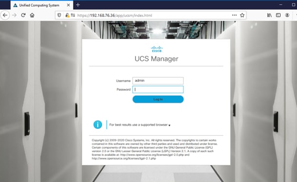
With the Fabric Interconnects configured continue the configuration from the web frontend of the Cisco UCS Manager. To access the frontend, follow these steps:
1. Open a web browser and navigate to the FI cluster address https://<var_ucs_cluster_ip>
2. Click Launch UCS Manager (accept the security certificate warning if prompted)
3. Enter the username “admin” and the Cisco UCS admin password <var_password> before you click Log In.
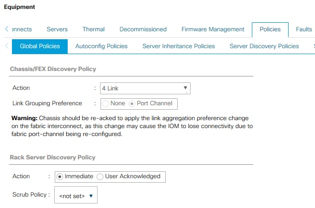
To modify the discovery policy to enable discovery of the Cisco UCS B-Series chassis and the Cisco UCS C-Series server connectivity, follow these steps:
1. In Cisco UCS Manager, click the Equipment tab in the navigation pane and select Equipment in the list on the left.
2. In the right pane, click the Policies tab.
3. Under Global Policies, set the Chassis/FEX Discovery Policy to match the number of uplink ports that are cabled between the chassis or fabric extenders (FEXes) and the fabric interconnects. Keep the port channel default for Link Grouping Preference.
4. Under Rack Server Discovery Policy change the action to Immediate.
5. Click Save Changes.
6. Click OK.
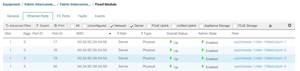
To enable server and uplink ports, follow these steps on both Fabric Interconnects:
1. In Cisco UCS Manager, click the Equipment tab in the navigation pane.
2. Select Equipment > Fabric Interconnects > Fabric Interconnect A|B (primary | subordinate) > Fixed Module.
3. Go to the Ethernet Ports tabulator.
4. Select the ports that are connected to the chassis and / or to the Cisco C-Series Server (two per FI), right-click them, and select Configure as Server Port.
5. Click Yes to confirm server ports and click OK.
6. Verify that the ports connected to the chassis and / or to the Cisco C-Series Server are now configured as server ports.
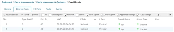
Configure Ethernet Uplink Ports
To configure the ethernet uplink ports, follow these steps on both Fabric Interconnects:
![]() Select ports in the range 49-54 for 40/100GE Uplink Port connectivity.
Select ports in the range 49-54 for 40/100GE Uplink Port connectivity.
1. Configure the ports connected to the N9Ks Ethernet Uplink Ports. The port range 17-48 provides 10/25GE uplink connectivity.
2. In Cisco UCS Manager, click the Equipment tab in the navigation pane.
3. Select Equipment > Fabric Interconnects > Fabric Interconnect A|B (primary | subordinate) > Fixed Module.
4. Go to the Ethernet Ports tabulator.
5. Select ports that are connected to the Cisco Nexus switches, right-click them, and select Configure as Uplink Port.
6. Click Yes to confirm uplink ports and click OK.
Enable FlashStack for volume provisioning used by the FlashStack UCS hosts to boot from Fibre Channel LUNs and used as application data volumes.
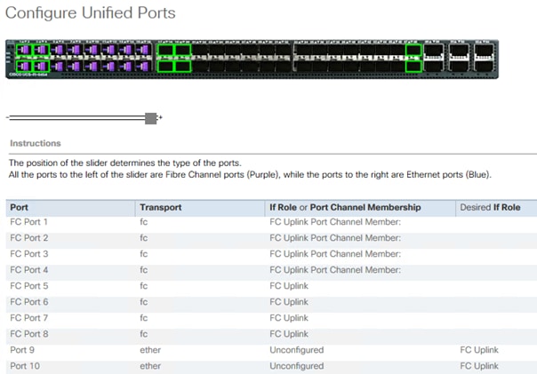
Configure Unified Ports
The Configure Unified Ports wizard allows you to change the port mode from Ethernet to Fibre Channel. Create the first set of ports from the left, for example ports 1-4 of the fixed module for Fibre Channel. Each of the other ports can be an Ethernet Uplink Port to the Nexus switches.
![]() While configuring the Fixed Module Ports, the slider bar movement enables sets of ports from the left of the module as FC ports. The remainder is available for Ethernet Uplinks. This step used 4 ports for uplink to MDS, it is sufficient to configure first set of 8 ports as FC ports.
While configuring the Fixed Module Ports, the slider bar movement enables sets of ports from the left of the module as FC ports. The remainder is available for Ethernet Uplinks. This step used 4 ports for uplink to MDS, it is sufficient to configure first set of 8 ports as FC ports.
Follow these steps on both Fabric Interconnects:
1. In Cisco UCS Manager, click the Equipment tab in the navigation pane.
2. Select Equipment > Fabric Interconnects > Fabric Interconnect A|B (primary | subordinate)
3. In the right pane General tab scroll to Actions and select Configure Unified Ports. Confirm the warning,
4. Move the slider bar to right to enable the first set of 8 ports for FC Uplink Role. Click OK.
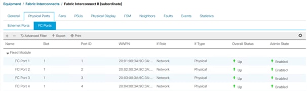
A change to the fixed module requires a reboot of the Fabric Interconnects. To reboot the FIs, follow these steps:
1. In Cisco UCS Manager, click the Equipment tab in the navigation pane.
2. Select Equipment > Fabric Interconnects > Fabric Interconnect A|B (primary | subordinate)
3. Expand the FC ports.
4. Select the ports connected to the Cisco MDS switch, right-click them and select Enable
5. Click Yes to confirm to enable the ports and click OK.
VSAN is a security mechanism for storage which can be compared to VLANs for the networks.
The storage connectivity is achieved through northbound Cisco MDS Fabric Switches. It is important to note that physical northbound storage connectivity does not support vPCs like LAN connectivity does and it is required to connect FI-A via MDS-A and FI-B via MDS-B towards the FlashArray//X. Fabric Interconnects do not cross connect with MDS switches.
Port channel configuration to combine multiple storage FC uplink ports to provide physical link redundancy is possible.
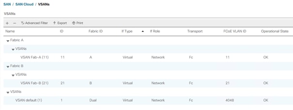
To configure VSAN, follow these steps:
1. In Cisco UCS Manager, click the SAN tab in the navigation pane.
2. Select SAN > SAN Cloud > VSANs.
3. Right-click VSANs and select Create VSAN.
4. Enter Fab-A as the name of the VSAN to be used for Fabric-A.
5. Retain ‘Disabled’ for FC Zoning option and select Fabric A. Enter VSAN ID <var_san_A_id> which maps to the VSAN on MDS-A. Use the same value for FCOE VLAN ID.
6. Click OK and then click OK again.
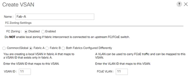
7. Repeat steps 1 - 6 to create VSAN Fab-B and use VSAN ID <var_san_B_id> which maps to the VSAN on MDS-B.
Configure the FC uplinks from the Fabric Interconnects towards the Cisco MDS fabric switches. A port channel bundles the interfaces into a group to provide increased bandwidth and redundancy and load balance the VSAN traffic. The port channel pair has corresponding F-port-channel-trunks defined on the MDS switches to allow the fabric logins from N Port Virtualization (NPV) enabled Fabric Interconnects. This provides non-disruptive redundancy should individual member links fail.
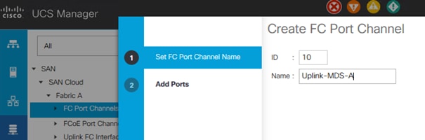
To configure the necessary port channels out of the Cisco UCS environment, follow these steps:
1. In Cisco UCS Manager, click the SAN tab in the navigation pane.
2. Under SAN > SAN Cloud, expand the Fabric A tree.
3. Right-click FC Port Channels.
4. Select Create FC Port Channel.
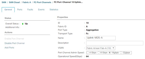
5. Enter the unique ID 10 and FC port channel name Uplink-MDS-A. Click Next.
6. Set Port Channel Admin Speed to 16gbps. Select the following ports to be added to the port channel:
◦ Slot ID 1 and port 1
◦ Slot ID 1 and port 2
◦ Slot ID 1 and port 3
◦ Slot ID 1 and port 4
![]() The selected port channel admin speed and ports is based on Uplink Port connectivity and device cabling in this lab setup and might deviate in your data center configuration.
The selected port channel admin speed and ports is based on Uplink Port connectivity and device cabling in this lab setup and might deviate in your data center configuration.
7. Click the >> symbol to add the ports to the FC port channel.
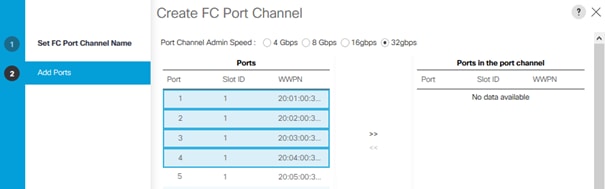
8. To create the port channel, click Finish.
9. Click OK
10. Under SAN > SAN Cloud, expand the Fabric B tree.
11. Right-click FC Port Channels.
12. Select Create FC Port Channel.
13. Enter the unique ID 20 and FC port channel name Uplink-MDS-B. Click Next.
14. Set Port Channel Admin Speed to 16gbps. Select the following ports to be added to the port channel:
◦ Slot ID 1 and port 1
◦ Slot ID 1 and port 2
◦ Slot ID 1 and port 3
◦ Slot ID 1 and port 4
![]() The selected port channel admin speed and ports is based on Uplink Port connectivity and device cabling in this lab setup and might deviate in your data center configuration.
The selected port channel admin speed and ports is based on Uplink Port connectivity and device cabling in this lab setup and might deviate in your data center configuration.
15. Click the >> symbol to add the ports to the FC port channel
16. To create the port channel, click Finish.
17. Click OK.
Assign Respective Fabric FC Channels to the VSANs
To assign the fc port channels to respective fabric VSAN just created, follow these steps:
1. In Cisco UCS Manager, click the SAN tab > SAN Cloud > Fabric A > FC Port Channels.
2. Select FC Port-Channel 10 Uplink-MDS-A
3. On the right pane, change the VSAN information from default (1) to Fab-A VSAN 10 created for Fabric-A.
4. Click the SAN tab > SAN Cloud > Fabric B > FC Port Channels.
5. Select FC Port-Channel 20 Uplink-MDS-B.
6. On the right pane, change the VSAN information from default (1) to Fab-B VSAN 20 created for Fabric-B.

Create LAN Uplink Port Channels
Configure the LAN uplinks from the Fabric Interconnects towards the northbound Nexus Switches. A port channel bundles the interfaces into a group to provide increased bandwidth and redundancy and load balance the SAP network zone traffic across these physical interfaces.
For example, create port channel 21 on FI-A and port channel 22 on FI-B. This port channel pairs have corresponding vPCs defined on N9Ks to ensure seamless redundancy and failover for the north-south network traffic in the rare case of an IOM or VIC port failure situation.
In this example configuration we use two pairs of 2 x 25GE ports for the connectivity between the FI and Nexus switch to handle the network traffic of all network zones except the internal node to node traffic. While this is sufficient for most of the use cases it is possible to extend the configuration and add additional port channel pairs if required to separate network intensive traffic like backup for example.
![]() The ports selection is based on Uplink Port connectivity and device cabling in this lab setup and might deviate in your data center configuration.
The ports selection is based on Uplink Port connectivity and device cabling in this lab setup and might deviate in your data center configuration.
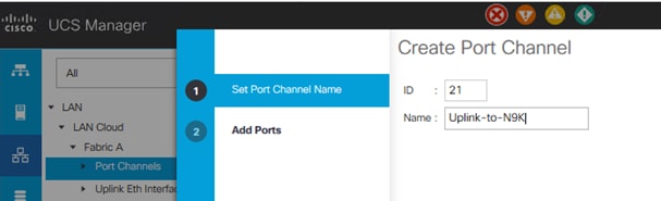
To configure the necessary port channels from FI-A and FI-B to the uplink Cisco Nexus switches follow these steps:
1. In Cisco UCS Manager, click the LAN tab in the navigation pane
2. Under LAN > LAN Cloud, expand the Fabric A tree.
3. Right-click Port Channels.
4. Select Create Port Channel.
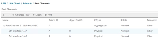
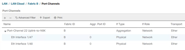
5. Enter the unique ID 21 and port channel name Uplink-to-N9K, then click Next.
6. Select the following ports and add them to the port channel:
◦ Slot ID 1 and port 47
◦ Slot ID 2 and port 48
7. Click the >> symbol to add the ports to the port channel.
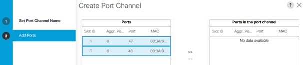
8. Click Finish to create the port-channel.
9. Click Ok.
10. Under LAN > LAN Cloud, expand the Fabric B tree.
11. Right-click Port Channels.
12. Select Create Port Channel.
13. Enter the unique ID 22 and port channel name Uplink-to-N9K, then click Next.
14. Select the following ports and add them to the port channel:
◦ Slot ID 1 and port 47
◦ Slot ID 2 and port 48
15. Click the >> symbol to add the ports to the port channel
16. To create the port channel, click Finish.
17. Click OK.
![]() A second uplink port channel set can be configured and exclusively used for backup network traffic.
A second uplink port channel set can be configured and exclusively used for backup network traffic.
Add Block of IP Addresses for KVM Access
To create a block of IP addresses for server Keyboard, Video, Mouse (KVM) access in the Cisco UCS environment, follow these steps:
![]() This block of IP addresses should be in the same subnet as the management IP addresses for the Cisco UCS Manager.
This block of IP addresses should be in the same subnet as the management IP addresses for the Cisco UCS Manager.
1. In Cisco UCS Manager, click the LAN tab in the navigation pane.
2. Select Pools > root > IP Pools > IP Pool ext-mgmt.
3. In the Actions pane, select Create Block of IPv4 Addresses.
4. Enter the starting IP address of the block and the number of IP addresses required, and the subnet and gateway information.
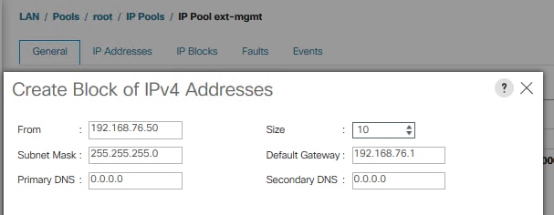
5. Click OK to create the IP block.
6. Click OK in the confirmation notification.
To run Cisco UCS with two independent power distribution units, the redundancy must be configured as Grid. Follow these steps:
1. In Cisco UCS Manager, click the Equipment tab in the navigation pane.
2. Select Equipment > Policies.
3. Select Global Policies in the work pane.
4. Set the Power Policy Redundancy to Grid.
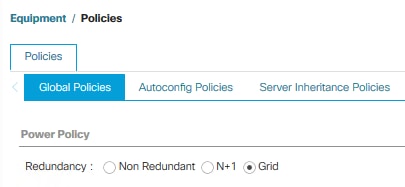
5. Click Save Changes.
6. Click OK.
Power Control Policy
The Power Capping feature in Cisco UCS is designed to save power in the data center. This feature conflicts with the high-performance behavior of SAP HANA. Choose the “No Cap” option for the power control policy to not restrict the power supply for the SAP HANA server nodes.
![]() A power control policy is recommended to ensure sufficient power supply for high-performance and critical workload applications like SAP HANA.
A power control policy is recommended to ensure sufficient power supply for high-performance and critical workload applications like SAP HANA.
To create a power control policy for the Cisco UCS environment, follow these steps:
1. In Cisco UCS Manager, click the Servers tab in the navigation pane.
2. Select Policies > root > Power Control Policies.
3. Right-click Power Control Policies and select Create Power Control Policy.
4. Enter HANA as the Power Control Policy name.
5. (Optional) Provide a description.
6. Set Fan Speed Policy to Performance from the drop-down list.
7. Enable the Power Capping radio button No Cap.
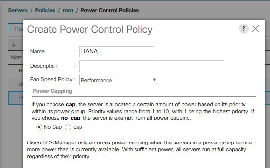
8. Click OK to create the power control policy.
9. Click OK.
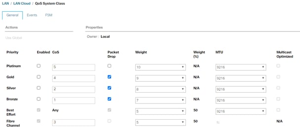
Set Jumbo Frames in Cisco UCS Fabric
The core network requirements for SAP HANA are covered by Cisco UCS defaults. The Service Profile is configured to distribute the traffic across Fabric Interconnect A and B.
To configure jumbo frames and enable quality of service in the Cisco UCS fabric, follow these steps:
1. In Cisco UCS Manager, click the LAN tab in the navigation pane.
2. Select LAN > LAN Cloud > QoS System Class.
3. In the right pane, click the General tab.
4. On the MTU Column, enter 9216 in the box.
5. Click Save Changes in the bottom of the window.
6. Click OK.
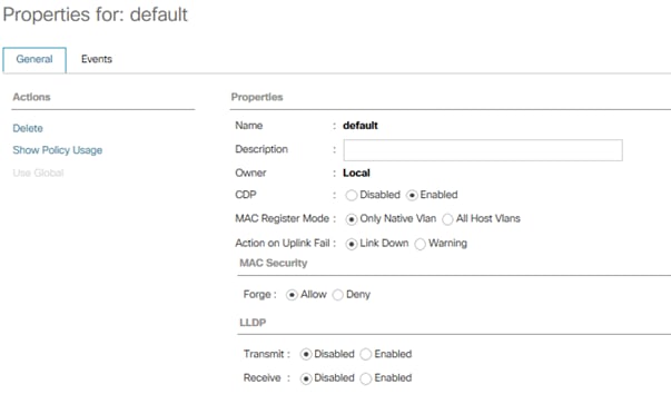
Enable CDP in the Default Network Control Policy
To enable the Cisco Discovery Protocol (CDP) to learn the MAC address of the End Point and to update the default Network Control Policy, follow these steps:
1. In Cisco UCS Manager, click the LAN tab in the navigation pane.
2. Select LAN > Policies > root > Network Control Policies.
3. Double-click Default in the work pane.
4. Select the Enabled button for CDP.
5. Click Save Changes in the bottom of the window.
6. Click OK.
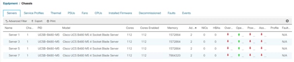
Acknowledge Cisco UCS Chassis and Rack-Mount Servers
To acknowledge all Cisco UCS chassis and/or Rack Mount Servers, follow these steps:
1. In Cisco UCS Manager, click the Equipment tab in the navigation pane.
2. Expand Chassis and select each chassis that is listed. Right-click each chassis and select Acknowledge Chassis.
3. Expand Rack-Mounts to the list the discovered servers. The servers automatically go into “Discovery” phase.
4. Ensure the Discovery completes successfully and there are no major or critical faults reported for any of the servers.
Firmware Update
Obtain the Cisco UCSM Release software bundles and transfer the Cisco UCS infrastructure software bundle, the related Cisco UCS B-Series and C-Series software bundle as well as the Capability Catalog file towards the Cisco Fabric Interconnect.
To update the firmware to the Cisco recommended release, review the Cisco UCS Manager Firmware Management Guide (https://www.cisco.com/c/en/us/td/docs/unified_computing/ucs/ucs-manager/GUI-User-Guides/Firmware-Mgmt/4-1/b_UCSM_GUI_Firmware_Management_Guide_4-1/b_UCSM_GUI_Firmware_Management_Guide_4-1_chapter_011.html).
![]() At the time of this validation the recommended firmware package release is 4.1(1c).
At the time of this validation the recommended firmware package release is 4.1(1c).
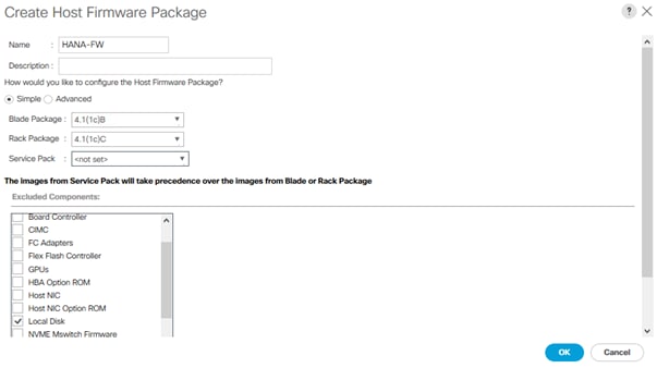
Firmware management policies allow the administrator to select the corresponding packages for a given server configuration. These policies often include packages for adapter, BIOS, board controller, FC adapters, host bus adapter (HBA) option ROM, and storage controller properties.
To create a firmware management policy for a given server configuration in the Cisco UCS environment, follow these steps:
1. In Cisco UCS Manager, click the Servers tab in the navigation pane.
2. Select Policies > root > Firmware Packages.
3. Right-click Host Firmware Packages and select Create Host Firmware Package.
4. Enter HANA-FW as the name of the host firmware package.
5. Leave Simple selected.
6. Select the version 4.1(1c) for both the Blade and Rack Packages.
7. Click OK to create the host firmware package.
8. Click OK.
Update Default Maintenance Policy
To update the default Maintenance Policy with the Reboot Policy “User Ack” for SAP HANA servers, follow these steps. This policy will wait for the administrator to acknowledge the server reboot for the configuration changes to take effect.
1. In Cisco UCS Manager, click the Servers tab in the navigation pane.
2. Select Policies > root.
3. Select Maintenance Policies > default.
4. Change the Reboot Policy to User Ack.
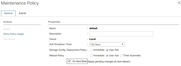
5. Click Save Changes.
6. Click OK to accept the change
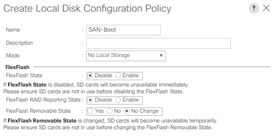
Create Local Disk Configuration Policy
All nodes are set to boot from SAN for this Cisco Validated Design as part of the Service Profile template. The benefits of booting from SAN are numerous; disaster recovery, lower cooling, and power requirements for each server since local drives are not required, as well as better performance, to name just a few.
![]() A local disk configuration is required only if the servers in the environment do have local disks.
A local disk configuration is required only if the servers in the environment do have local disks.
To configure local disk policy, follow these steps:
1. In Cisco UCS Manager, click the Servers tab in the navigation pane.
2. Select Policies > root > Local Disk Config Policies
3. Right-click Local Disk Config Policies and select create local disk configuration policy
4. Provide SAN-Boot as policy name
5. Change the mode drop down box to No Local Storage
6. Keep the other defaults and confirm with OK.
Within Cisco UCS, all the network types for an SAP HANA system are manifested by defined VLANs. Network design guideline from SAP recommends seven SAP HANA related networks and two infrastructure related networks.
The total number of VLANs depends on the SAP HANA installation scenario and might differ in a customer environment. If there is no SAP HANA System Replication configured the replication network is needless. The same applies for the internal host communication network when there is no Scale Out scenario required.
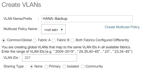
The VLAN IDs can be changed if required to match the VLAN IDs in the customer’s network – for example, ID 221 for backup should match the configured VLAN ID at the customer uplink network switches.
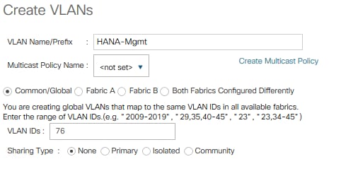
To configure the necessary VLANs for the Cisco UCS environment, follow these steps:
1. In Cisco UCS Manager, click the LAN tab in the navigation pane.
2. Select LAN > LAN Cloud > VLANs.
3. Right-click VLANs and select Create VLANs.
4. Enter HANA-Mgmt as VLAN name of the HANA Management network.
5. Keep the Common/Global option selected for the scope of the VLAN.
6. Enter <var_oob_vlan_id> as the ID of the HANA Node to Node network.
7. Keep the Sharing Type as None.
8. Click OK and confirm with OK.
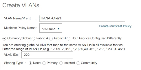
9. Repeat steps 1-8 to create all required VLANs.
10. Create VLAN HANA-Client using <var_client_vlan_id>
11. Create VLAN HANA-AppServer using <var_appserver_vlan_id>
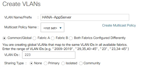
12. Create VLAN HANA-DataSource using <var_datasource_vlan_id>
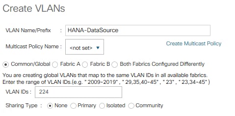
13. Create VLAN HANA-Backup using <var_backup_vlan_id>
14. Create VLAN HANA-Replication using <var_replication_vlan_id>
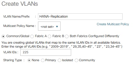
15. Create VLAN HANA-Internal Node to Node traffic using <var_internal_vlan_id>
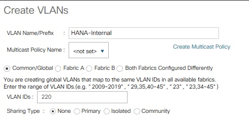
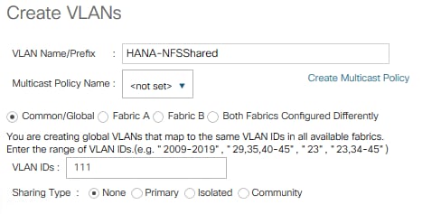
16. Create VLAN HANA-NFSshared for /hana/shared NFS network.
The summary of all previous created VLANs is shown below:

Create VLAN Groups to simplify the management and bandwidth allocation to a dedicated uplink on the Fabric Interconnect. SAP groups recommended SAP HANA networks into zones which translates to VLAN Groups in the Cisco UCS configuration:
● Client Zone – including AppServer, Client and DataSource networks
● Internal Zone – including Inter-node and System Replication networks
● Storage Zone – including Backup and IP storage networks
● (optional) Admin zone – including Management or Linux cluster network if any
![]() For this deployment guide we create four VLAN Groups. Depending on customer requirements and SAP HANA scenario the number of VLAN Groups might differ in a customer environment.
For this deployment guide we create four VLAN Groups. Depending on customer requirements and SAP HANA scenario the number of VLAN Groups might differ in a customer environment.
To configure the recommended VLAN Groups for the Cisco UCS environment, follow these steps:
1. In Cisco UCS Manager, click the LAN tab in the navigation pane.
2. Select LAN > LAN Cloud > VLAN Groups.
3. Right-click VLAN Groups and select Create VLAN Groups.
4. Enter Admin-Zone as the name of the VLAN Group used for Infrastructure network.
5. Select VLAN HANA-Mgmt.
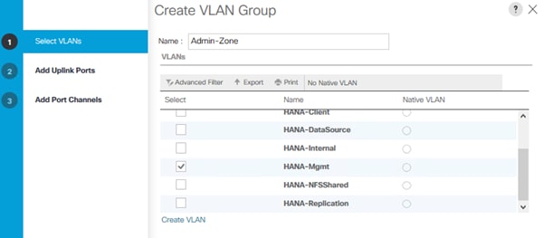
6. Click Next.
7. Click Next on Add Uplink Ports.
8. Select the uplink network port channels previously created and add them.
9. Click Finish.
10. Repeat steps 1-9 to create VLAN Group Client-Zone and add VLANs HANA-AppServer, HANA-Client and HANA-DataSource.
11. Repeat steps 1-9 to create VLAN Group Internal-Zone and add VLANs HANA-Internal and HANA-Replication
12. Repeat steps 1-9 to create VLAN Group Storage-Zone and add VLANs HANA-Backup and HANA-NFSShared
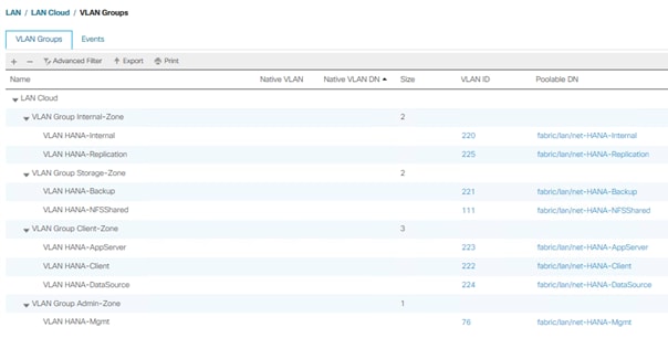
Create LAN Connectivity Policy
A LAN Connectivity Policy in the target organization (HANA) forces the device ordering through Consistent Device Naming (CDN). The policy avoids manual reordering of ethernet devices during the Linux installation. An alternative configuration is to specify the vNIC and vHBA placement manually in the process of creating the service profile template.
To create the LAN connectivity policy, follow these steps:
1. In the Navigation pane, click LAN.
2. Select LAN > Policies > root > Sub-Organizations > HANA > LAN Connectivity Policies.
3. Right-click LAN Connectivity Policies and select Create LAN Connectivity Policy.
4. Use LAN-HANA as policy name.
5. (Optional) provide a policy description.
6. Click the Add button to add a vNIC.
7. In the Create vNIC dialog box, use HANA-Mgmt as vNIC name.
8. Check mark the use vNIC Template box.
9. In the vNIC Template drop-down menu, select HANA-Mgmt.
10. Set the Adapter Policy to Linux.
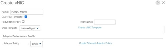
11. Click OK to add this vNIC to the policy.
12. Click Add to add all other vNIC.
13. Click OK to create the LAN Connectivity Policy and click OK again.
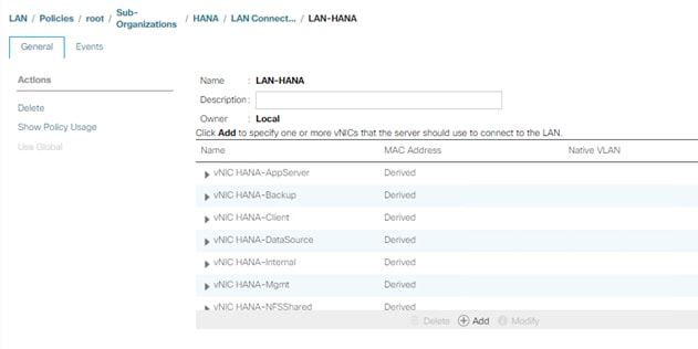
Multi-Tenancy Environment
Multi-tenancy allows to divide up the large physical infrastructure of an instance into logical entities known as organizations. As a result, you can achieve a logical isolation between organizations without providing a dedicated physical infrastructure for each organization.
Assign unique resources to each tenant through the related organization, in the multi-tenant environment these resources can include different policies, pools, and quality of service definitions. In a multi-tenant environment, all organizations are hierarchical. The top-level organization is always root. The policies and pools created in root are system-wide and are available to all organizations in the system. However, any policies and pools created in other organizations are only available to organizations that are above it in the same hierarchy.
For secure multi-tenancy within the Cisco UCS domain create an organization for the SAP HANA deployment.
Create New Organization
To create a new organization, follow these steps:
1. In Cisco UCS Manager, click Quick Actions.
2. From the drop-down list select Create Organization.
3. Enter the Name as HANA.
![]() Optionally use a different naming convention to divide SAP production, test, sandbox, training, and development environments
Optionally use a different naming convention to divide SAP production, test, sandbox, training, and development environments
4. (Optional) Enter the Description as Org for HANA.
5. Click OK to create the Organization.
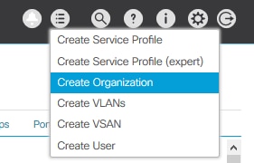
Create UUID Suffix Pool
To configure the universal unique identifier (UUID) suffix pool for the Cisco UCS environment, follow these steps:
1. In Cisco UCS Manager, click the Servers tab in the navigation pane.
2. Select Pools > root > Sub-Organization > HANA > UUUID Suffix Pools
3. Right-click UUID Suffix Pools and select Create UUID Suffix Pool.
4. Enter UUID-Pool as name of the UUID suffix pool.
5. (Optional) Enter a description for the UUID suffix pool.
6. Keep the Prefix as the Derived option.
7. Select Sequential for Assignment Order
8. Click Next.
9. Click Add to add a block of UUIDs.
10. Keep the ‘From’ field at the default setting.
11. Specify the UUID block size sufficient to support the available blade or server resources.
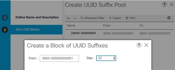
12. Click OK.
13. Click Finish and then click OK.
To achieve the best performance, the SAP HANA environment needs to configure the Server BIOS accurately. To create a server BIOS policy for the Cisco UCS environment, follow these steps:
1. In Cisco UCS Manager, click the Servers tab in the navigation pane.
2. Select Policies > root > Sub-Organization > HANA > BIOS Policies.
3. Right-click BIOS Policies and select Create BIOS Policy.
4. Enter HANA-BIOS as BIOS policy name.
5. Select Reboot on BIOS Settings Change.
6. Click OK and confirm the new BIOS Policy with OK.
7. Select the HANA-BIOS policy in the navigation pane.
8. On the Main sub tab, change the Quiet Boot setting from Platform Default to Disabled.
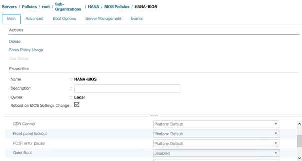
9. Change to the Advanced sub tab.
10. In the processor sub-tab, change CPU Performance from Platform Default to Enterprise.
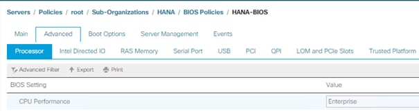
11. Keep processor C State on platform default
12. Keep Processor C1E on Platform Default
13. Change Processor C3, C6 and C7 Report to disabled.
14. Change Power Technology from Platform Default to Performance.
15. Change Energy Performance from Platform Default to Performance.
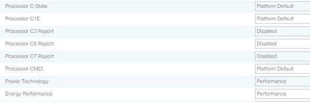
16. In the RAS Memory tab change the LV DDR Mode to performance mode and enable NUMA. Keep the memory RAS configuration on platform default.
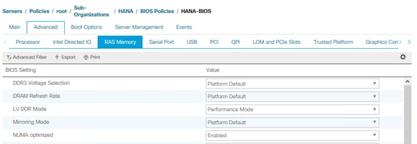
17. Enable Serial Port A in the Serial Port tab.
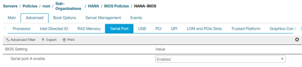
18. In the Server Management tab, configure the Console Redirection to serial-port-a with the BAUD Rate 115200 and enable the feature Lega-cy OS redirect. This is used for Serial Console Access over LAN to all SAP HANA servers.
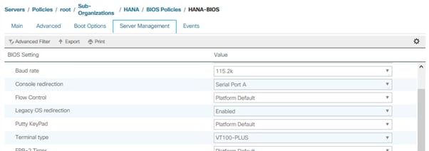
19. Click Save Changes to update the BIOS Policy.
20. Click OK.
Create Boot Policy for SAN Boot
Use “Boot from SAN” to realize full benefits of Cisco UCS stateless computing features such as service profile mobility such as service profile mobility.
The Pure Storage FlashArray//X controller ports are cross connected with the MDS switches to provide alternate paths to the LUNs, in addition to the built-in redundancy and path management features of the FlashArray//X itself.
The Cisco MDS-A switch connects to FlashArray//X controller 0 and SAN port CT0.FC1 and to FlashArray//X Controller 1 and SAN port CT1.FC1 as well as the SAN ports CT0.FC3 and CT1.FC3. The Cisco MDS-B switch connects to both controllers and ports FC0 and FC2 accordingly.
Determine the WWPN information of these storage array target ports from the Purity//FA GUI.
Figure 3. Pure Storage FlashArray//X - FC Target Ports
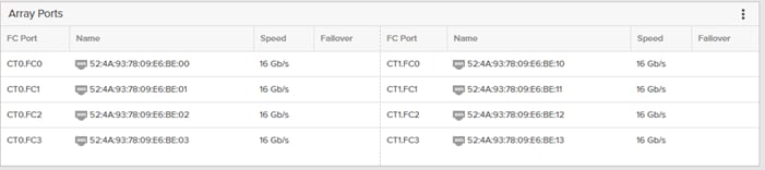
The SAN Boot policy requires a primary (vhba-a) and secondary (vhba-b) path, both with a primary and secondary boot target each. For the primary path configure SAN port CT0.FC1 as primary target and SAN port CT1.FC1 as secondary target. For the secondary path configure SAN port CT1.FC0 as primary target and SAN port CT0.FC1 as secondary target.
To create a SAN boot policy for the HANA organization, follow these steps:
1. In Cisco UCS Manager, click the Servers tab in the navigation pane.
2. Select Servers > Policies > root > Sub-Organizations > HANA > Boot Policies.
3. Right-click and select Create Boot Policy.
4. Enter HANA-SANboot as boot policy name.
5. Checkmark Enforce vNIC/vHBA/iSCSI Name
6. Select the Boot Mode radio button UEFI.
7. Ensure there is no checkmark for Boot Security.
8. Expand the Local Devices menu and select Add CD/DVD.
9. Expand the vHBAs menu and select Add SAN Boot.
10. Select type Primary.
11. Enter vhba-a in the vHBA field and click OK.
12. Select Add SAN Boot Target.
13. Change Boot Target LUN to 1.
![]() Pure Storage FlashArray//X reserves LUN ID 0 for internal purpose.
Pure Storage FlashArray//X reserves LUN ID 0 for internal purpose.
14. Enter the WWPN of SAN port CT0.FC1.
15. Select Type Primary and click OK.
16. Add a secondary SAN Boot target to the same vhba-a. Select Add SAN Boot Target
17. Change Boot Target LUN to 1.
18. Enter the WWPN of SAN port CT1.FC0 and click OK.
19. Add the secondary SAN boot target. Select Add SAN Boot.
20. Enter vhba-b in the vHBA field and click OK.
21. Select Add SAN Boot Target
22. Change Boot Target LUN to 1.
23. Enter the WWPN of SAN port CT1.FC0.
24. Select Type Primary and click OK.
25. Add a secondary SAN Boot target to the same vhba-b. Select Add SAN Boot Target
26. Change Boot Target LUN to 1
27. Enter the WWPN of SAN port CT0.FC1 and click OK.
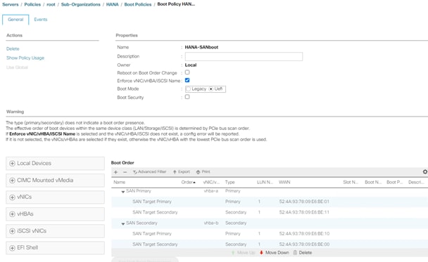
28. Click OK and confirm with OK.
Create an IPMI/Redfish Access Profile
In the SAP HANA Scale-Out scenario, IPMI enables the HANA internal high availability functionality. To create an IPMI/Redfish access profile, follow these steps:
1. In Cisco UCS Manager, click the Servers tab in the navigation pane.
2. Select Servers > Policies > root > Sub-Organizations > HANA > IPMI/Redfish Access Profiles.
3. Right-click IPMI/Redfish Access Profile and select Create IPMI/Redfish Access Profile.
4. Provide the profile name HANA-IPMI
5. (Optional) Add a description
6. Keep IPMI/Redfish Over LAN enabled.
7. Click add to add an IPMI/Redfish user
8. Provide a username <var_ipmi_username>
9. Provide an IPMI password: <var_ipmi_password> and confirm the password.
10. Change the role to Admin and click OK.
The Serial over LAN policy is required to enable SSH console access to all SAP HANA servers from the management network. This is useful if the server hangs or in the event of a Linux kernel crash when a dump file is required.
To create a Serial over LAN policy, follow these steps:
1. In Cisco UCS Manager, click the Servers tab in the navigation pane.
2. Select Policies > root > Sub-Organization > HANA > Serial over LAN Policies.
3. Right-click Serial over LAN Policies and select Create Serial over LAN Policy.
4. Enter SoL-Console as the Policy name.
5. Enable Serial over LAN.
6. Change the Speed to 115200.
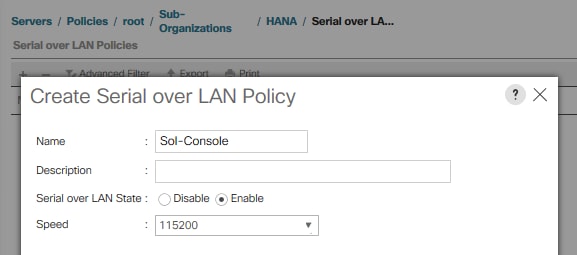
7. Click OK.
Create MAC Address Pools
To configure the necessary MAC address pool in the Cisco UCS environment for each Fabric Interconnect, follow these steps:
1. In Cisco UCS Manager, click the LAN tab in the navigation pane.
2. Select Pools > root > Sub-Organization > HANA > MAC Pools.
3. Right-click and select Create MAC Pool to create the MAC address pool.
4. Enter FI-A as the name of the MAC pool.
5. (Optional) Enter a description for the MAC pool.
6. Choose Assignment Order Sequential.
7. Click Next.
8. Click Add.
9. Specify a starting MAC address.
10. Specify a size for the MAC address pool that is sufficient to support the available blade or server resources.
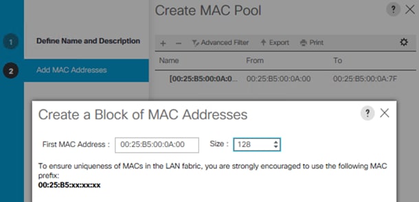 .
.
11. Click OK.
12. Click Finish.
13. In the confirmation notification, click OK.
14. Right-click MAC Pools under the HANA organization.
15. Select Create MAC Pool to create the MAC address pool.
16. Enter FI-B as the name of the MAC pool.
17. (Optional) Enter a description for the MAC pool. Select ‘Sequential’ for Assignment order.
18. Click Next.
19. Click Add.
20. Specify a starting MAC address.
21. Specify a size for the MAC address pool that is sufficient to support the available blade or server resources.
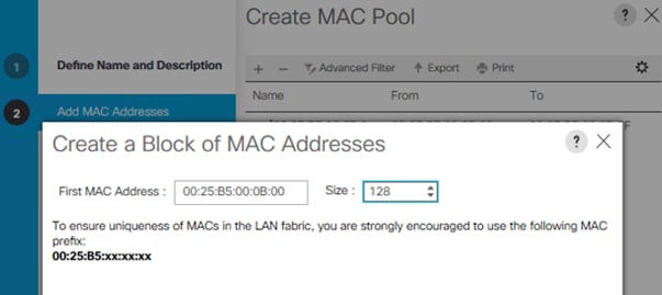
22. Click OK.
23. Click Finish and then click OK.
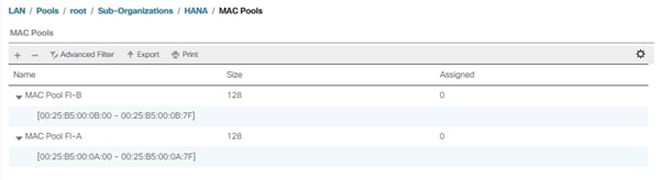
Each VLAN is mapped to a vNIC template to specify the characteristic of a specific network. The vNIC template configuration settings include MTU size, Failover capabilities and MAC-Address pools.
To create vNIC templates for the Cisco UCS environment, follow these steps:
1. In Cisco UCS Manager, click the LAN tab in the navigation pane.
2. Select Policies > root > Sub-Organization > HANA > vNIC Templates.
3. Right-click vNIC Templates and select Create vNIC Template.
4. Enter HANA-Internal as the vNIC template name.
5. (Optional) Provide a vNIC Template description
6. Keep Fabric A selected (alter to Fabric B for the next vNIC Template)
7. Check the Enable Failover checkbox.
8. Under Target, ensure the VM checkbox is unchecked.
9. Select Template Type Updating Template.
10. Select the HANA-Internal VLAN.
11. Enable the native VLAN radio button for the VLAN HANA-Internal.
12. Change the MTU to the maximum value 9000.
13. Select the MAC Pool list for FI-A (Select FI-B for the next vNIC Template)
14. Select Default from the drop-down list of Network Control Policy.
15. Keep all other settings default
16. Click OK to create the vNIC template.
17. Confirm the new vNIC template with OK.
![]() For optimal performance a MTU size of 9000 is recommended for all vNICs. For the management vNIC the MTU size of 1500 or 9000 is optional.
For optimal performance a MTU size of 9000 is recommended for all vNICs. For the management vNIC the MTU size of 1500 or 9000 is optional.
18. Continue to create a vNIC template for each VLAN altering the FI-A and FI-B assignments.
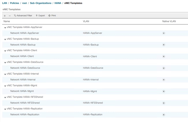
Create WWNN Pool
To configure the WWNN pool for the HANA organization in the Cisco UCS environment, follow these steps:
1. In Cisco UCS Manager, click the SAN tab in the navigation pane.
2. Select Pools > root > Sub-Organization > HANA > WWNN Pools.
3. Right-click WWNN Pools and select Create WWNN Pool.
4. Enter HANA-Nodes as the name of the WWNN pool.
5. (Optional) Enter a description for the WWNN pool.
6. Choose Assignment Order Sequential.
7. Click Next.
8. Click Add.
9. Specify a starting WWNN address.
10. Specify a size for the WWNN pool that is sufficient to support the available blade or server resources.
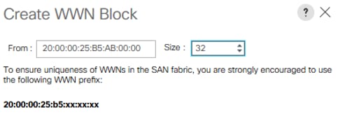
11. Click OK.
12. Click Finish and confirm with OK.
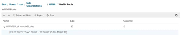
To configure each Fabric Interconnect with the WWPN pool in the Cisco UCS environment, follow these steps:
1. In Cisco UCS Manager, click the SAN tab in the navigation pane.
2. Select Pools > root > Sub-Organization > HANA > WWPN Pools.
3. Right-click WWPN Pools and select Create WWPN Pool.
4. Enter FI-A as WWPN pool name.
5. (Optional) Enter a description for the WWPN pool.
6. Choose Assignment Order Sequential.
7. Click Next.
8. Click Add.
9. Specify a starting WWN address.
10. Specify a size for the WWPN address pool that is sufficient to support the available blade or server resources.
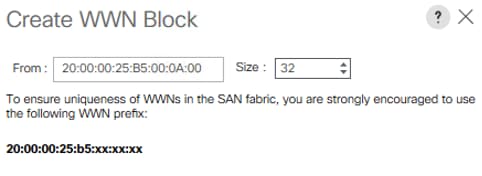
11. Click OK.
12. Click Finish and OK to confirm the confirmation notification.
13. Right-click WWPN Pools under the HANA organization again.
14. Select Create WWPN Pool to create another WWNN address pool.
15. Enter FI-B as the name of the WWPN pool.
16. (Optional) Enter a description for the WWPN pool. Select ‘Sequential’ for Assignment order.
17. Click Next.
18. Click Add.
19. Specify a starting WWPN address.
20. Specify a size for the WWPN address pool that is sufficient to support the available blade or server resources.
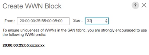
21. Click OK.
22. Click Finish and then click OK.
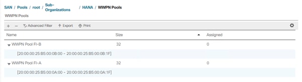
Create vHBA Template
To create one dedicated vHBA template for each Fabric Interconnect, follow these steps:
1. In Cisco UCS Manager, click the SAN tab in the navigation pane.
2. Select SAN > Policies > root > Sub-Organizations > HANA > vHBA Templates.
3. Right-click vHBA Templates and select Create vHBA Template.
4. Choose vHBA-A as template name.
5. (Optional) Provide a description.
6. Select Fabric ID A
7. Select VSAN Fab-A and Template Type Updating template.
8. Select WWPN Pool FI-A.
9. Click OK and then click OK again.
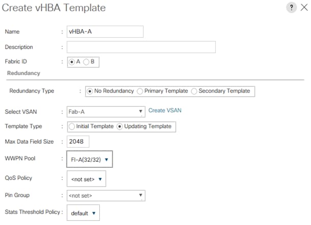
10. Right-click vHBA Templates and select Create vHBA Template.
11. Choose vHBA-B as template name.
12. (Optional) Provide a description.
13. Select Fabric ID B
14. Select VSAN Fab-B and Template Type Updating template.
15. Select WWPN Pool FI-B.
16. Click OK and then click OK again.
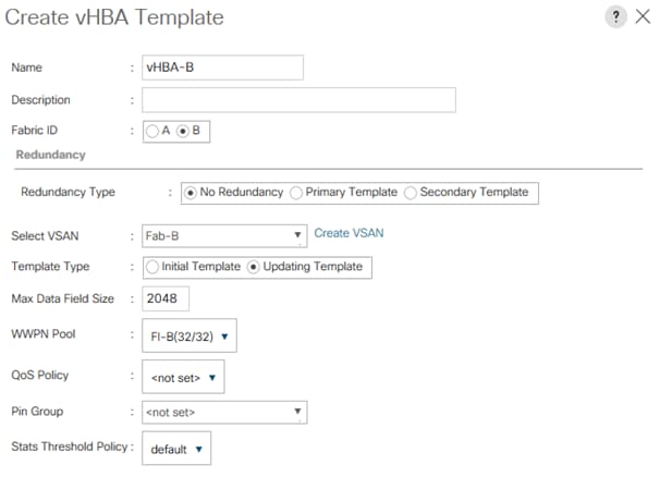
Create SAN Connectivity Policy
After establishing the physical connectivity, configure the zoning for the servers and the SAN:
● Storage connection policies: This configures the storage connectivity considering the WWPN Target numbers. Since Zoning is handled by the MDS switches and the FIs aren’t direct attached to the Storage, a storage connection policy is not required.
● SAN connectivity policies: This configures vHBAs for the servers which will provide WWPN Initiator numbers for the servers. This server-side configuration is necessary to prepare the server connection towards the storage.
To configure the storage connection policy, follow these steps:
1. In Cisco UCS Manager, click the SAN tab in the navigation pane.
2. Select SAN > Policies > root > Sub-Organizations > HANA > SAN Connectivity Policies.
3. Right-click SAN Connectivity Policies and select Create SAN Connectivity Policy.
4. Enter the SAP Connectivity policy name HANA-SAN.
5. (Optional) Add a description.
6. Select HANA-Nodes from the WWNN Assignment drop-down list.
7. Click Add to add the vHBAs from the vHBA templates previously created.
8. In the Create vHBA window, provide a name as vhba-a.
9. Checkmark the “Use vHBA Template” option.
10. Select vHBA-A from the vHBA Template drop-down list and Linux from the Adapter Policy drop-down list.
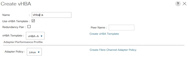
11. Click OK
12. Click Add in the Create SAN Connectivity Policy window to add another vHBA
13. In the Create vHBA window, provide name as vhba-b.
14. Checkmark the “Use vHBA Template” option.
15. Select vHBA-B from the vHBA Template drop-down list and Linux from the Adapter Policy drop-down list.
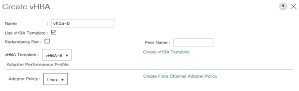
16. Click OK.
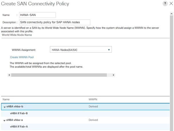
17. Click OK and then click with OK again.
Create SAP HANA Service Profile Template
To create SAP HANA Service Profile template, follow these steps:
1. In Cisco UCS Manager, click the Servers tab in the navigation pane.
2. Select Service Profile Templates > root > Sub-Organization > HANA.
3. Right-click HANA and select Create Service Profile Template.
4. In the Create Service Profile Template wizard enter a service profile template name.
5. Select the radio button Updating Template.
6. Change the UUID assignment and select the UUID pool from the drop-down list.
7. (Optional) Add a description.
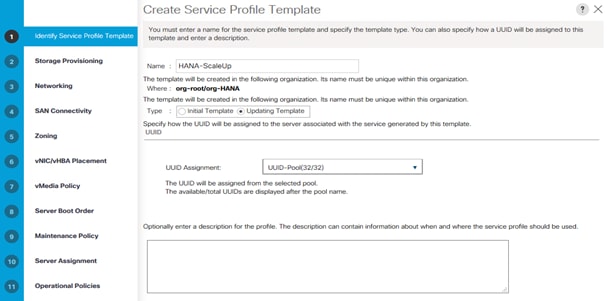
8. Click Next.
9. Skip Storage Provisioning and click Next.
10. Select the Use Connectivity Policy radio button on the question how to configure the LAN connectivity.
11. Select FC-LAN-HANA from the LAN Connectivity Policy drop-down list and click Next.
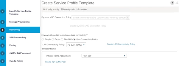
12. Select HANA-Nodes from the WWNN Assignment drop-down list.
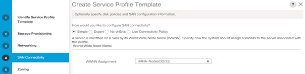
13. Enable the radio button Use Connectivity Policy on the top.
14. Select HANA-SAN from the SAN Connectivity Policy drop-down list.
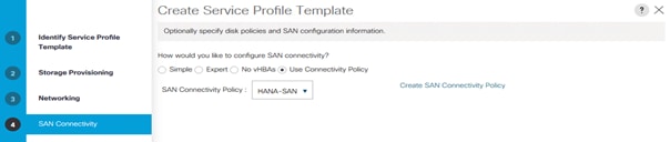
15. Click Next.
16. Skip Zoning and click Next.
17. Keep Let System Perform Placement in the drop-down list.
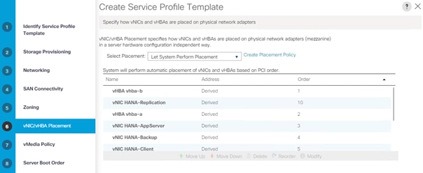
18. Click Next.
19. Skip vMedia Policy and click Next.
20. Select HANA-SANboot from the Boot Policy drop-down list.
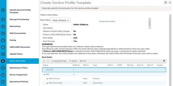
21. Click Next.
22. Select default from the Maintenance Policy drop-down list and click Next.
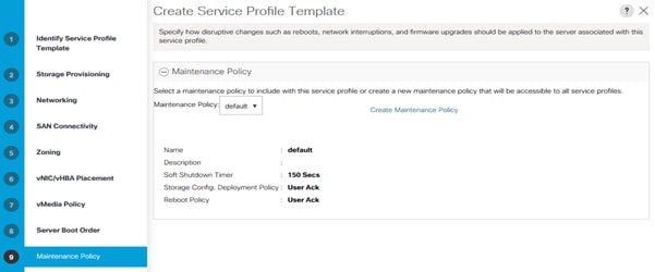
23. Enable the Power State Down radio button.
24. Expand Firmware Management and select HANA-FW from the Host Firmware Package drop-down list.
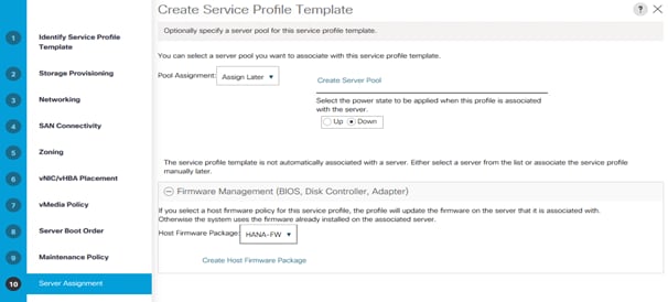
25. Click Next.
26. In BIOS Configuration select HANA-BIOS from the BIOS Policy drop-down list.
27. Select the HANA-IPMI profile from the IPMI/Redfish Access Profile drop-down list.
28. Select Sol-Console from the SoL Configuration Profile drop-down list.
29. In Management IP Address select ext-mgmt from the Management IP Address Policy drop-down list in the Outband IPv4 tab.
30. In Power Control Policy Configuration select HANA from the Power Control Policy drop-down list.
31. In the Scrub Policy select default from the Scrub Policy drop-down list.
32. In KVM Management Policy select default from the KVM Management Policy drop-down list.
33. In Graphics Card Policy select default from the Graphics Card Policy drop-down list.
34. Click Finish to create the service profile template and then click OK.
Create Service Profile from the Template
To create service profiles using the service profile template, follow these steps:
1. In Cisco UCSM, click the Servers tab in the navigation pane.
2. Select Servers > Service Profile Templates > root > Sub-Organization > HANA.
3. Right-click HANA and select Create Service Profiles from Template.
4. Enter HANA-Server0 as the service profile prefix.
5. Enter 4 as Name Suffix Starting Number.
6. Enter 1 as the Number of Instances
7. Select the HANA Service Profile Template from the drop-down list.
8. Click OK to create the Service Profile from the Template.
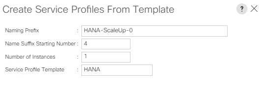
9. Select Servers > Service Profiles > root > Sub-Organizations > HANA > HANA-Server04.
10. Right-click HANA-Server04 and select Change Service Profile Association.
11. Choose Select existing Server from the Server Assignment drop-down list.
12. Enable the radio button Available Servers and select the server to assign.
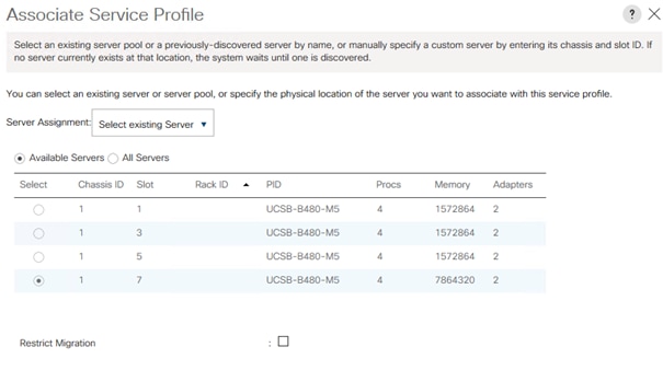
13. Click OK, confirm the warning by clicking Yes and then click OK.
The traditional zoning method allows each device in a zone to communicate with every other device in the zone. Smart zoning allows the configuration of initiator-target pairs using fewer hardware resources than previously required. The device type information of each device in a smart zone is automatically populated from the Fibre Channel Name Server (FCNS) database.
To collect the WWPN information from UCSM and to enable the Pure Storage Administration UI to prepare the zoning configuration of the MDS switch, follow these steps:
1. In Cisco UCS Manager, click the Servers tab in the navigation pane.
2. Select Servers > Service Profiles > root > Sub-Organization > HANA > HANA-Server04
3. In the working pane, click the storage tab and the vHBAs sub tab to receive the WWPN of the HBA’s.
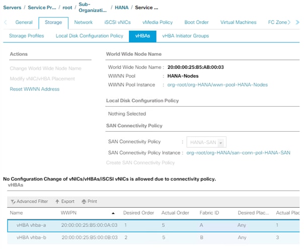
4. Note down the WWPN of all configured servers from the service profiles.
5. Connect to the Pure Storage Administration UI to collect the WWPN of the FC ports connected to the Cisco MDS switches. Each of the two FlashArray//X controller CT0 and CT1 connects with 4 FC ports to the Cisco MDS switches.
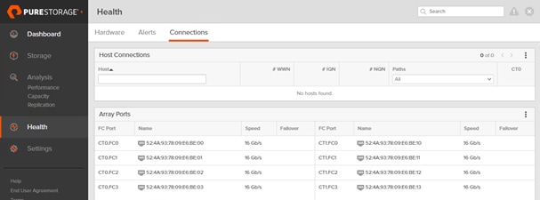
Create Device Aliases for the Fiber Channel Zoning
To configure device aliases and zones for the primary boot paths, follow these steps:
1. SSH to MDS-A and run the following commands:
MDS-A # conf t
MDS-A(config)# device-alias database
MDS-A(config-device-alias-db)#
device-alias name HANA-node01-hba-a pwwn 20:00:00:25:b5:00:0A:03
device-alias name HANA-node02-hba-a pwwn 20:00:00:25:b5:00:0A:02
device-alias name HANA-node03-hba-a pwwn 20:00:00:25:b5:00:0A:01
device-alias name HANA-node04-hba-a pwwn 20:00:00:25:b5:00:0A:00
device-alias name Pure-CT0.FC1 pwwn 52:4A:93:78:09:E6:BE:01
device-alias name Pure-CT1.FC1 pwwn 52:4A:93:78:09:E6:BE:11
device-alias name Pure-CT0.FC3 pwwn 52:4A:93:78:09:E6:BE:03
device-alias name Pure-CT1.FC3 pwwn 52:4A:93:78:09:E6:BE:13
MDS-A(config-device-alias-db)# exit
MDS-A(config)# device-alias commit
2. SSH login to MDS-B and run the following commands:
MDS-B # conf t
MDS-B(config)# device-alias database
MDS-B(config-device-alias-db)#
device-alias name HANA-node01-hba-b pwwn 20:00:00:25:b5:00:0B:03
device-alias name HANA-node02-hba-b pwwn 20:00:00:25:b5:00:0B:02
device-alias name HANA-node03-hba-b pwwn 20:00:00:25:b5:00:0B:01
device-alias name HANA-node04-hba-b pwwn 20:00:00:25:b5:00:0B:00
device-alias name Pure-CT0.FC0 pwwn 52:4A:93:78:09:E6:BE:00
device-alias name Pure-CT0.FC2 pwwn 52:4A:93:78:09:E6:BE:02
device-alias name Pure-CT1.FC0 pwwn 52:4A:93:78:09:E6:BE:10
device-alias name Pure-CT1.FC2 pwwn 52:4A:93:78:09:E6:BE:12
MDS-B(config-device-alias-db)# exit
MDS-B # device-alias commit
Create Zoning
This section details how to configure zones on both MDS switches for each service profile.
![]() To enable SAP HANA failover capabilities, add all SAP HANA nodes as member of the same zone.
To enable SAP HANA failover capabilities, add all SAP HANA nodes as member of the same zone.
To SSH login to MDS-A. This example creates two zones, one for a Scale-Out and another for a Scale-Up deployment, run the following commands:
1. Create zones:
MDS-A(config)# zone name HANA-ScaleOut-a vsan 10
MDS-A(config-zone)# member device-alias Pure-CT0.FC1
MDS-A(config-zone)# member device-alias Pure-CT1.FC1
MDS-A(config-zone)# member device-alias Pure-CT0.FC3
MDS-A(config-zone)# member device-alias Pure-CT1.FC3
MDS-A(config-zone)# member device-alias HANA-node01-hba-a
MDS-A(config-zone)# member device-alias HANA-node02-hba-a
MDS-A(config-zone)# member device-alias HANA-node03-hba-a
MDS-A(config-zone)# exit
MDS-A(config)# zone name HANA-node04-a vsan 10
MDS-A(config-zone)# member device-alias Pure-CT0.FC1
MDS-A(config-zone)# member device-alias Pure-CT1.FC1
MDS-A(config-zone)# member device-alias Pure-CT0.FC3
MDS-A(config-zone)# member device-alias Pure-CT1.FC3
MDS-A(config-zone)# member device-alias HANA-node04-hba-a
MDS-A(config-zone)# exit
2. Create zone set and add members:
MDS-A(config)# zoneset name HANA-Nodes-A vsan 10
MDS-A(config-zoneset)# member HANA-ScaleOut-a
MDS-A(config-zoneset)# member HANA-node04-a
MDS-A(config-zoneset)# exit
3. Activate the zone set:
MDS-A(config)# zoneset activate name HANA-Nodes-A vsan 10
MDS-A(config)# exit
4. Persist the configuration:
MDS-A # copy run start
To SSH login to MDS-B and run the following commands:
1. Create zones:
MDS-B(config)# zone name HANA-ScaleOut-b vsan 20
MDS-B(config-zone)# member device-alias Pure-CT0.FC0
MDS-B(config-zone)# member device-alias Pure-CT1.FC0
MDS-B(config-zone)# member device-alias Pure-CT0.FC2
MDS-B(config-zone)# member device-alias Pure-CT1.FC2
MDS-B(config-zone)# member device-alias HANA-node01-hba-b
MDS-B(config-zone)# member device-alias HANA-node02-hba-b
MDS-B(config-zone)# member device-alias HANA-node03-hba-b
MDS-B(config-zone)# exit
MDS-B(config)# zone name HANA-node04-b vsan 20
MDS-B(config-zone)# member device-alias Pure-CT0.FC0
MDS-B(config-zone)# member device-alias Pure-CT1.FC0
MDS-B(config-zone)# member device-alias Pure-CT0.FC2
MDS-B(config-zone)# member device-alias Pure-CT1.FC2
MDS-B(config-zone)# member device-alias HANA-node04-hba-b
MDS-B(config-zone)# exit
2. Create zone set and add members:
MDS-B(config)# zoneset name HANA-Nodes-B vsan 20
MDS-B(config-zoneset)# member HANA-ScaleOut-b
MDS-B(config-zoneset)# member HANA-node04-b
MDS-B(config-zoneset)# exit
3. Activate the zone set:
MDS-B(config)# zoneset activate name HANA-Nodes-B vsan 20
MDS-B(config)# exit
4. Persist the configuration:
MDS-B # copy run start
Verify Fiber Channel Connectivity
To verify the fibre channel connectivity, follow these steps:
1. Power-On the Cisco UCS Servers for the first time to verify the WWPN ports connect properly.
2. In Cisco UCS Manager, click the Equipment tab in the navigation pane.
3. Select Equipment > Chassis > Servers > Server 1
4. In the General work pane select the action KVM console
5. Follow the onscreen notifications and open the console to confirm the boot progress.
6. In the General work pane select the action Boot Server.
7. Confirm the popup windows with OK.
8. On both MDS switches verify the connectivity:
MDS-[A] # show flogi database
--------------------------------------------------------------------------------
INTERFACE VSAN FCID PORT NAME NODE NAME
--------------------------------------------------------------------------------
fc1/29 10 0x880060 52:4a:93:78:09:e6:be:01 52:4a:93:78:09:e6:be:01
[Pure-CT0.FC1]
fc1/30 10 0x880020 52:4a:93:78:09:e6:be:11 52:4a:93:78:09:e6:be:11
[Pure-CT1.FC1]
fc1/31 10 0x880040 52:4a:93:78:09:e6:be:03 52:4a:93:78:09:e6:be:03
[Pure-CT0.FC3]
fc1/32 10 0x880000 52:4a:93:78:09:e6:be:13 52:4a:93:78:09:e6:be:13
[Pure-CT1.FC3]
port-channel10 10 0x880080 24:0a:00:3a:9c:3a:54:40 20:0a:00:3a:9c:3a:54:41
port-channel10 10 0x880081 20:00:00:25:b5:00:0a:03 20:00:00:25:b5:ab:00:03
[HANA-node01-hba-a]
port-channel10 10 0x880082 20:00:00:25:b5:00:0a:00 20:00:00:25:b5:ab:00:00
[HANA-node04-hba-a]
port-channel10 10 0x880083 20:00:00:25:b5:00:0a:02 20:00:00:25:b5:ab:00:02
[HANA-node02-hba-a]
port-channel10 10 0x880084 20:00:00:25:b5:00:0a:01 20:00:00:25:b5:ab:00:01
[HANA-node03-hba-a]
Total number of flogi = 9.
MDS-A # show zoneset active
zoneset name HANA-Nodes-A vsan 10
zone name HANA-ScaleOut-a vsan 10
* fcid 0x880060 [pwwn 52:4a:93:78:09:e6:be:01] [Pure-CT0.FC1]
* fcid 0x880040 [pwwn 52:4a:93:78:09:e6:be:03] [Pure-CT0.FC3]
* fcid 0x880020 [pwwn 52:4a:93:78:09:e6:be:11] [Pure-CT1.FC1]
* fcid 0x880000 [pwwn 52:4a:93:78:09:e6:be:13] [Pure-CT1.FC3]
* fcid 0x880081 [pwwn 20:00:00:25:b5:00:0a:03] [HANA-node01-hba-a]
* fcid 0x880083 [pwwn 20:00:00:25:b5:00:0a:02] [HANA-node02-hba-a]
* fcid 0x880084 [pwwn 20:00:00:25:b5:00:0a:01] [HANA-node03-hba-a]
Pure Storage FlashArray//X Configuration
Host Configuration
To set up a host, follow these steps in the Purity//FA GUI:
![]() All hosts need to be powered on to make use of the host auto discovery feature of the FlashArray//X. Alternatively it is possible to add the host WWN manually.
All hosts need to be powered on to make use of the host auto discovery feature of the FlashArray//X. Alternatively it is possible to add the host WWN manually.
1. Login to the Purity//FA dashboard at http://<var_purecluster_ip>
2. Select Storage in the navigation pane.
3. Select Hosts in the work pane. To create a host, click the + sign on the right.
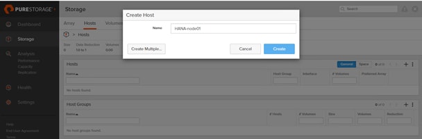
4. Enter the host name and click Create.
5. Update the host with the connectivity information and provide the Fibre Channel WWNs. Select the HANA-node01 host in the hosts work pane.
6. In the Host Ports pane click the settings button and select “Configure WWNs.”
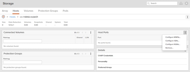
7. Select the vhba-a and vhba-b PWWNs from the listed WWNs.
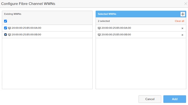
8. Click Add.
Configure SAN Boot Volume
To configure a single SAN boot volume that will become the master template for additional boot volume clones, follow these steps:
1. Select the Storage - Volumes tab in the navigation pane.
2. In the Volumes work pane click the + sign to create a new volume.
3. Provide a volume name and choose the appropriate volume size.
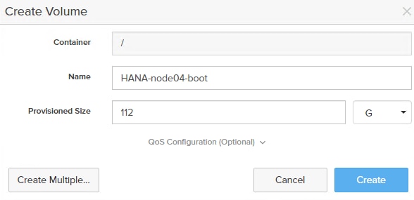
4. Click Create.
5. Select the new volume in the volumes work pane.
6. In the Connected Hosts work pane click Connect to connect the new volume.
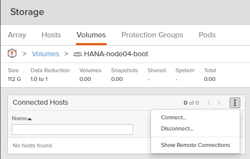
7. Change the LUN ID to 1 for the boot LUN.
8. Checkmark the new volume and click Connect.
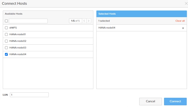
9. Repeat steps 1-8 to create and connect new boot volumes for each new SAP HANA worker node in the FlashStack environment.
SAP HANA Data and Log Volumes
Create the SAP HANA data and log volumes for each SAP HANA worker node and connect them to the appropriate host. Follow the sizing recommendations provided in section Pure Storage FlashArray//X Configuration.
The sizing recommendations deviate for SAP HANA Scale-Up and Scale-Out scenarios and so the host group configuration described below. To enable the SAP HANA failover capabilities and to add the shared volume to a host group which is shared with all hosts to ensure it receives the same LUN ID regardless of which host mounts the data or log volume, follow these steps:
1. In the navigation pane select Storage and Volumes in the work pane.
2. In the Volumes pane click the + sign to create an SAP HANA data volume.
3. Provide an SAP HANA data volume name and choose the appropriate volume size.
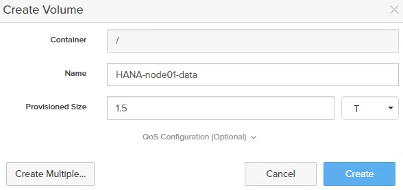
4. Select Create.
5. In the Volumes work pane click the + sign to create an SAP HANA log volume.
6. Provide an SAP HANA log volume name and choose the appropriate volume size.
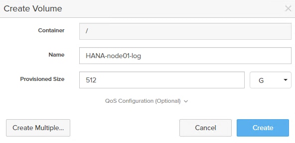
7. Select Create.
8. In the Volumes pane select the HANA-node01-data volume link.
9. In the connected Hosts pane select Connect from the menu bar.
10. In the Connect Host dialog, select the host and keep the LUN ID on automatic.
11. Select Connect.
12. In the Volumes pane select the HANA-node01-log volume link.
13. In the connected Hosts pane select Connect from the menu bar.
14. In the Connect Host dialog, select the host and keep the LUN ID on automatic.
15. Select Connect.
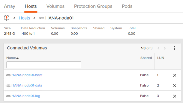
SAP HANA Shared Volume
In addition to the SAP HANA data and log volumes, the SAP HANA installation requires an SAP HANA shared volume as well. The configuration itself depends on the SAP HANA scenario.
SAP HANA Scale-Up
The SAP HANA Scale-Up deployment requires a locally mounted SAP HANA shared volume. Recommended volume size is 1TB. To configure the SAP HANA Scale-Up, follow these steps:
1. In the navigation pane select Storage and Volumes in the work pane.
2. In the Volumes work pane click the + sign to create an SAP HANA shared volume.
3. Provide an SAP HANA shared volume name and choose 1 TB volume size.
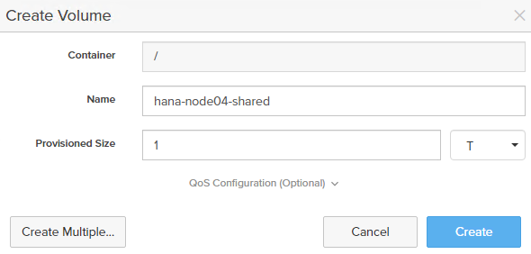
4. Click Create.
5. In the Volumes pane select the HANA-node04-shared volume link.
6. In the connected Hosts pane select Connect from the menu bar.
7. In the Connect Host dialog, select the host and keep the LUN ID on automatic.
8. Select Connect.
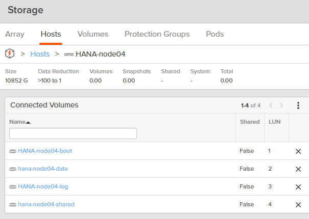
SAP HANA Scale-Out
Other than for SAP HANA Scale-Up the SAP HANA shared volume needs to be accessible from all nodes through NFS at the same time. This requires additional configuration effort compared to the Scale Up deployments.
Starting from Pure's Purity//FA 4.10.9, each controller can host a VM instance of Microsoft Windows Server 2016 which form a Windows Failover Cluster (WFS). File Servers within this cluster serve as NFS shares.
Each WFS VM resides on its own boot volume. For Windows clustering purposes, a default quorum witness volume is available to both WFS VMs. In addition, a default data volume hosts file services data. Subsequent data volumes can be created if additional capacity is required. Data volumes are exported to both WFS VMs to ensure persistent data across a WFS VM failover.
More information about the best practices for WFS on the Purity RUN platform is available in the Pure Technical Services documentation.
WFS requirements for the FlashArray//X:
● FlashArray Support: Two 10G iSCSI services ports on each controller for cluster and file services client traffic
● Domain Controller: Microsoft Failover Cluster requires a domain controller; therefore, a working domain controller must exist to run WFS.
● Domain Administrator Privileges: Customers must have appropriately elevated Domain Administrator privileges to perform many of the required setup steps like the following:
◦ Configuring WFS VM IP addresses
◦ Creating Microsoft Failover Clusters
◦ Creating File Servers
● DNS Server: There must be a functional DNS server in the environment to run file services with WFS. The two WFS VMs, Failover Cluster, and File Servers will be given a default hostname as shown in Table A. Customers have the option of using the given default hostnames or to specify their own hostnames.
● IP Addresses: A minimum of six IP addresses are required to run WFS.
![]() Pure Support performs the WFS cluster setup and configuration based on the provided user account and IP information.
Pure Support performs the WFS cluster setup and configuration based on the provided user account and IP information.
To configure the SAP HANA Scale-Out, follow these steps:
1. Verify the WFS storage configuration from the navigation pane Storage and Hosts work pane by selecting the @WFS host link.
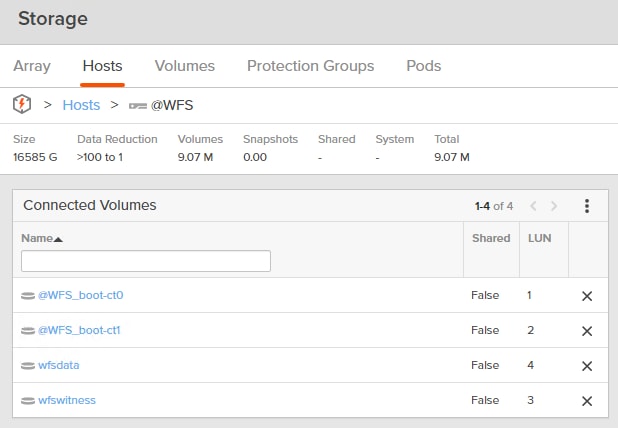
2. Like adding new volumes to an external host connected to the FlashArray//X, use the same steps to add a new volume and connect it to the WFS host. Create a new volume with a size of 1.5TB.
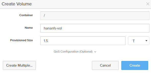
3. Connect the Volume to the @WFS host.
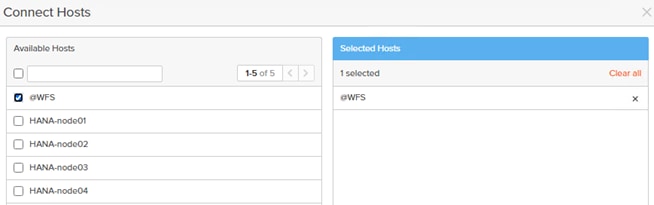
4. Use a VNC viewer to connect to one side of the WFS cluster. Start Computer Management > Disk Management and rescan the disks from the menu selection.
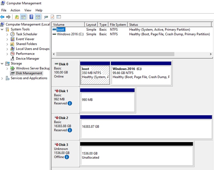
In this lab configuration disk 3 with 1536GB space shows up as new disk. Using the Disk Management menu change the disk from offline to online, initialize the disk and create an NTFS file system for the complete volume. Ensure both WFS VMs can see the disk. In the validation setup, a 1.5TB drive appears as disk 3 in both VMs.
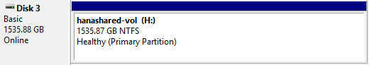
To configure a new file server role on the WFS VM, follow these steps:
1. In the Failover Cluster Manager, expand the cluster tree, highlight Disks, and select Add Disk.
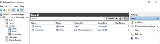
2. Select the newly created volume and click OK. The new volume appears on the list of available disks.
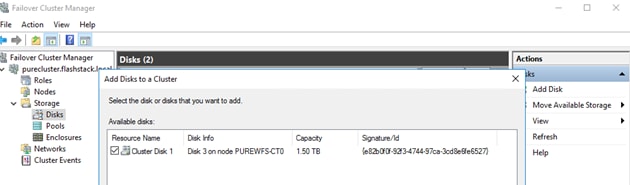
3. In the Failover Cluster Manager select the cluster tree, highlight Roles, and right-click Configure Role. In the select role dialog, select the option File Server, click Next.
4. Select the default “File Server for general use” option as File Server Type; click Next.
5. In the Client Access Point tab, provide the Share name hananfs and ensure the right IP network is selected. Specify the IP address and click Next.
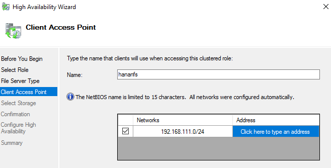
6. In the Select Storage dialog screen, select the available Cluster Disk and click Next.
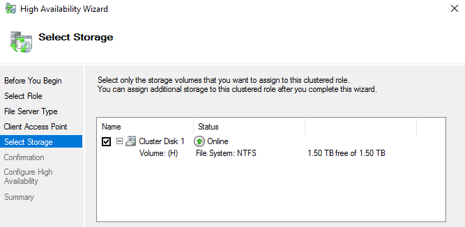
7. Click Next in the following dialog screens and the click Finish in the Summary dialog screen.
The SAP HANA File Server role configuration is done ready to support NFS shares.
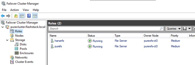
SAP HANA installations require additional configuration steps for the NFS share exported from a Microsoft Windows Server to function correctly. Correct permissions regarding a group identifier (GID) and user identifier(UID) need to be in place which link two active directory users with full access to the windows share.
![]() LDAP authentication capabilities in Red Hat Enterprise Linux or SUSE Enterprise Linux are not required.
LDAP authentication capabilities in Red Hat Enterprise Linux or SUSE Enterprise Linux are not required.
Create a group in Active Directory
During the SAP software installation, the user group sapsys will be created typically with the default GID of 79. While it is possible to change the GID to a different number it is key to have the GID information available prior of the SAP softer installation.
To create a group in Active Directory, follow these steps:
1. Open the Active Directory Users and Computers management console.
2. Right-click Users in the Domain tree and select New and then Group.
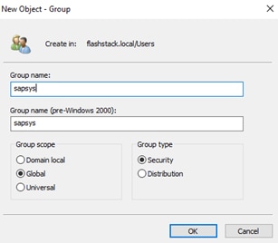
3. Create a <sid>adm user which fits name and GID wise to the SAP instance being installed.
4. Right-click on Users in the Domain tree and select New and then User.
5. Provide the username and logon name. In the validation setup the SAP SID is ANA; hence anaadm in this example.
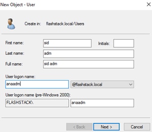
6. Provide a user password and set the password to never expire.
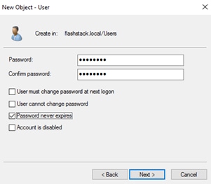
![]() Do not add the <sid>adm user to the sapsys group. This will be done automatically during the share creation process later.
Do not add the <sid>adm user to the sapsys group. This will be done automatically during the share creation process later.
7. Right-click on Users in the Domain tree and select New and then Group.
8. Provide the username and logon name.
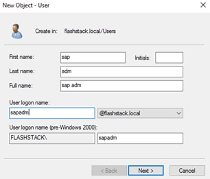
9. Provide a user password and set the password to never expire.
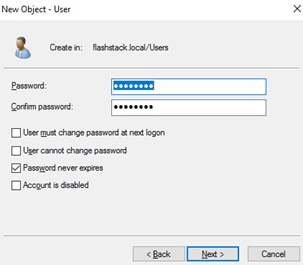
To connect to the Windows File Services VM, follow these steps:
1. Open the Server Manager.
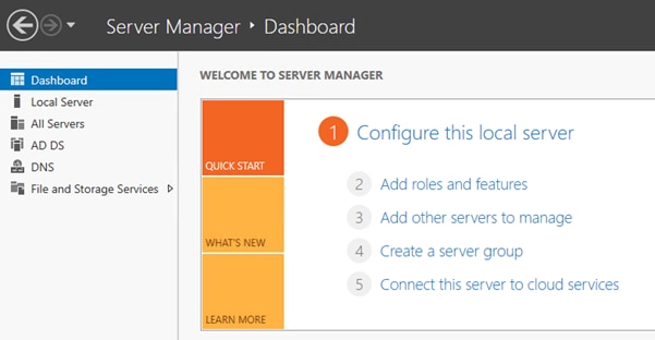
2. Navigate to the File and Storage Services.
3. Select the hananfs File Server and right-click to select NFS Settings from the menu.
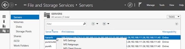
4. In the dialog screen set the relevant protocol versions (version 3 and 4.1 are recommended). Set the lease period to 90 seconds and the NFS v4.1 grace period to 180 seconds.
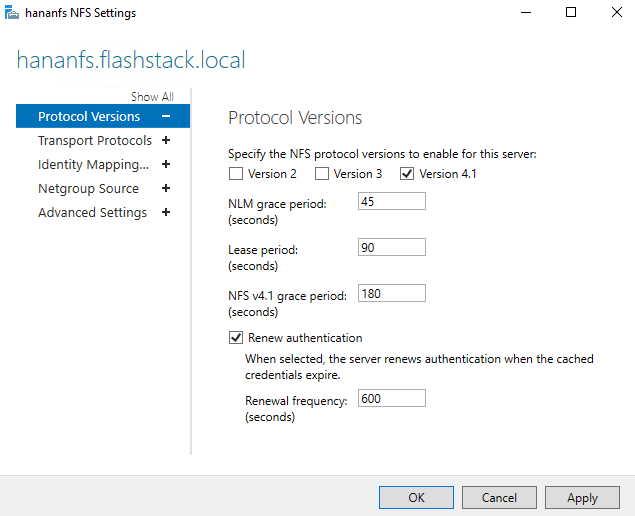
5. Change to Identity Mapping and set the identity mapping source which is the Active Directory Domain Service. Click OK.
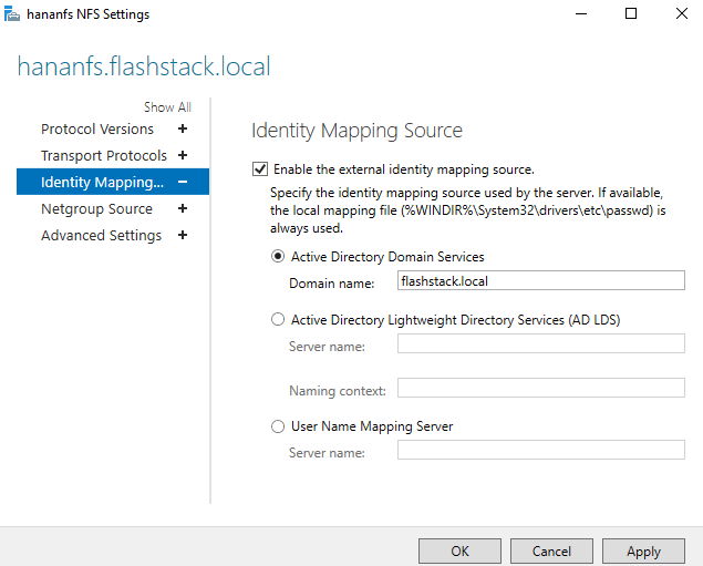
6. Return to File and Storage Services.
7. Select the hananfs File Server and right-click to select NFS Identity Mapping from the menu.
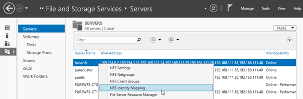
8. In the NFS Identity dialog screen, select New in the mapped groups work pane.
9. Provide the sapsys group with the same GID expected to be used for the SAP HANA installation.
10. Browse the domain for the sapsys group and confirm the dialogs to add the group.
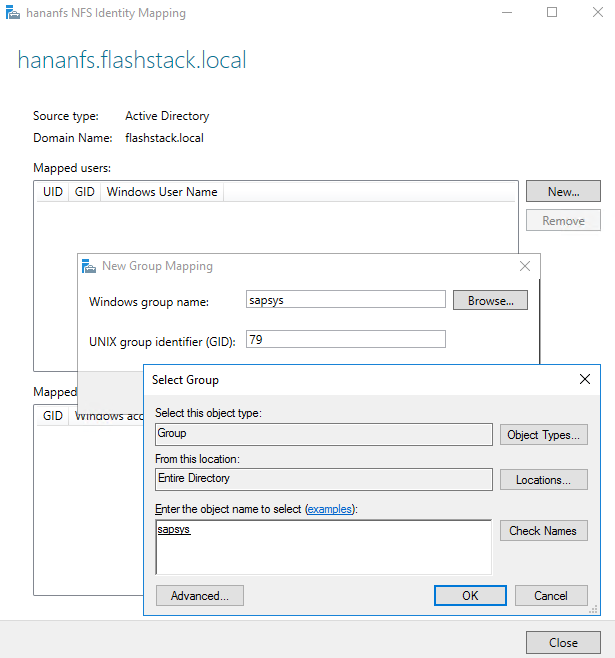
11. In the NFS Identity dialog screen, select New in the mapped users work pane.
12. Provide the <sid>adm user with the same UID expected to be used for the SAP HANA installation.
13. Browse the domain for the <sid>adm user and confirm the dialogs to add the user.
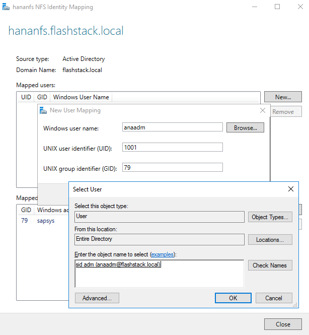
14. In the NFS Identity dialog screen, select New in the mapped users work pane.
15. Provide the sapadm user with the same UID expected to be used for the SAP HANA installation.
16. Browse the domain for the sapadm user and confirm the dialogs to add the user.
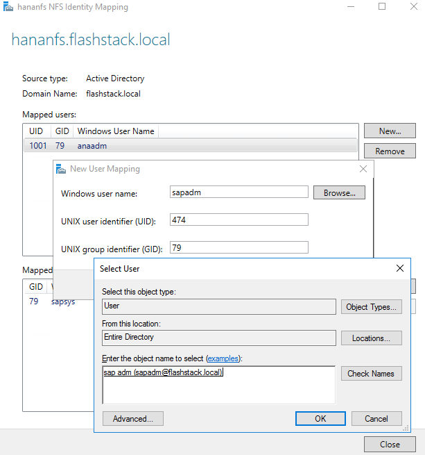
17. Confirm and close the dialog screen.
The NFS service in Windows File Services can map credentials in the domain to an NFS GID and UID.
Set up NFS Share and Configure Permissions
A single volume and drive should be presented for the NFS share. The use of drive letters is recommended but mount points are possible too.
To connect to the Windows File Services VM, follow these steps:
1. In Server Manager, navigate to Files and Storage Service and the sub menu Shares.
2. Click TASKS and select New Share.
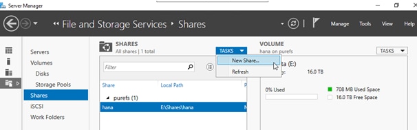
3. Select NFS Share - Quick and click Next.
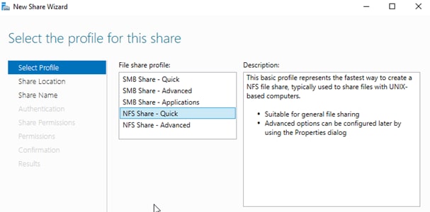
4. Select the hananfs server name and its volume. Click Next.
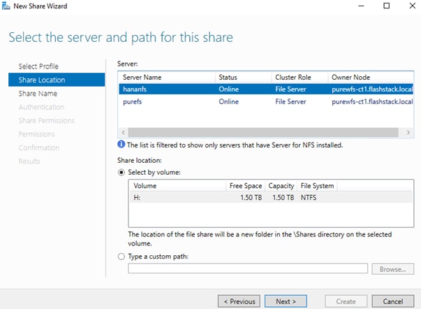
5. Provide a share name and click Next.
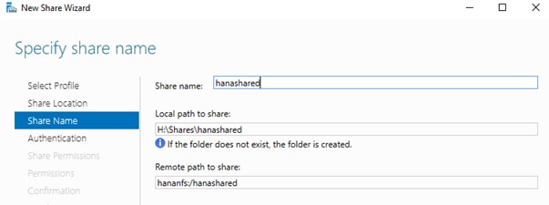
6. Select the Authentication method: No server authentication (AUTH_SYS).
7. Select Enable unmapped user access and Allow unmapped user access by UID/GID.
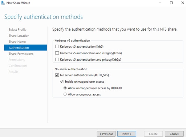
8. Click Next.
9. Select either individual hosts names (or IP addresses), groups or all host machines to allow access to the NFS share. In the lab environment we select All Machines.
10. Set the share permission to Read/Write and select Allow root access.
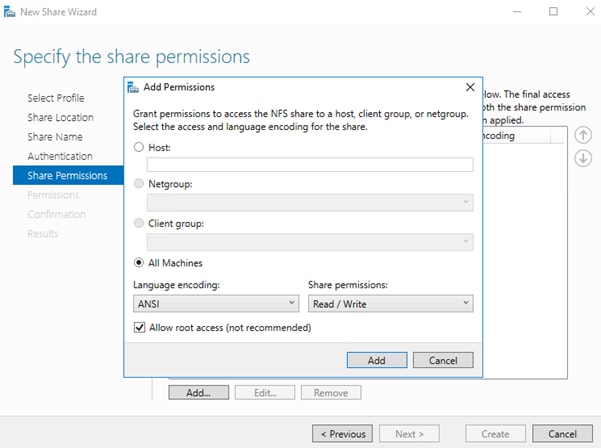
11. Click Add.
12. Verify the selected hosts, groups or all machines appear and click Next.
13. In the permission work pane, click Customized permissions.
14. In the Advanced Security Settings for hanashared click Add.
15. Click Select a Principal
16. In the empty boy, type sapsys and Click Check Names.
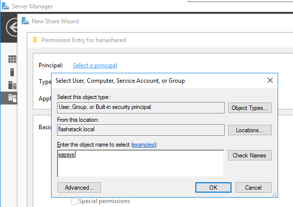
17. Click OK.
18. Select the Full Control checkmark.
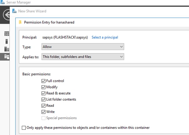
19. Add everyone as new principal and select the Full Control checkmark as well.
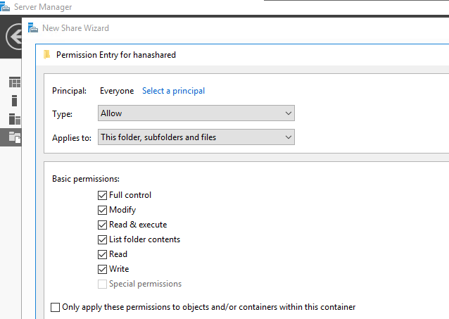
20. Confirm the selections and click Create. Click Close the confirmation dialog.
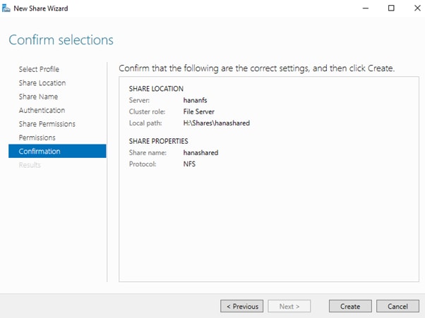
The new share is now visible from Server Manager and will be used as /hana/shared file system during the SAP HANA Scale-Out installation.
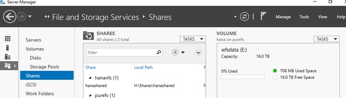
21. Use the default NFS mount options when mounting this HANA NFS share:
# cat /etc/fstab
192.168.111.26:/hanashared /hana/shared nfs defaults 0 0
This section provides the Linux Operating System installation procedure using SAN Boot and includes operating system customization to fulfill all SAP HANA requirements. If you plan to install Red Hat Enterprise Linux for SAP Solutions skip the first SUSE Linux Enterprise Server for SAP Applications installation section.
SLES for SAP Applications 15 SP1
SLES for SAP 15 Installation
SUSE® Linux Enterprise Server for SAP Applications is the reference platform for the software development of SAP. It is optimized for SAP applications like SAP HANA. The installation follows the installation workflow documented in chapter 3.1 of https://documentation.suse.com/sles-sap/15-SP1/html/SLES4SAP-guide/index.html and this section lists where the lab installation deviates from the installation workflow.
The following supplement SUSE information is available from the SAP notes system:
● SAP Note 2578899 - SUSE Linux Enterprise Server 15: Installation Note
● SAP Note 2684254 - SAP HANA DB: Recommended OS settings for SLES 15 for SAP Applications 15
● SAP Note 1275776 - Linux: Preparing SLES for SAP environments
To download the ISO image from https://download.suse.com and map the installation ISO image in the KVM console, follow these step:
1. In the Navigation pane of the Cisco UCS Manager, click Servers.
2. Select Service Profile > root > Sub-Organization > HANA > HANA-Server01.
3. In the Actions section click KVM Console.
4. Choose Virtual Media > Activate Virtual Devices.
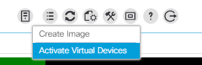
5. For Unencrypted Virtual Media Session, select Accept this Session and then click Apply.
6. Click Virtual Media and choose Map CD/DVD.
7. Click Browse to navigate to the ISO media location. Select SLE-15-SP1-Installer-DVD-x86_64-GM-DVD1.ISO Click Open.
8. Click Map Device.
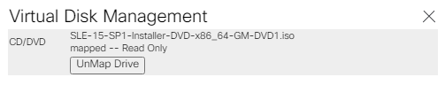
9. In the KVM Console menu, click Boot Server.
10. During the VIC FC boot driver verification at the server boot time the Pure Storage FlashArray//X target WWPN numbers are listed during the connection verification.
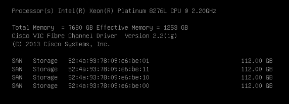
11. The System will automatically boot from the ISO image into the installation wizard.
![]() Follow the SUSE Linux Enterprise installation workflow and choose SUSE Linux Enterprise Server for SAP Applications 15 SP1.
Follow the SUSE Linux Enterprise installation workflow and choose SUSE Linux Enterprise Server for SAP Applications 15 SP1.
12. On the network settings screen configure the management network interface.
13. Identify the Ethernet device to vNIC interface mapping first from the Cisco UCS Manager:
a. In the Navigation pane of UCSM, click Servers
b. Select Service Profile > root > Sub-Organizations > HANA > HANA-Server01
c. In the network tab, scroll down to the vNIC section and list the vNICs with their MAC addresses
d. Note down the MAC address of the HANA-Mgmt vNIC, in this lab installation “00:25:B5:00:0B:02”
14. In the SUSE network settings screen, find the network interface with the same MAC address, in this lab installation eth5 and click edit.
15. Provide the IP address <var_server01_mgmt_ip>, the subnet mask <var_oob_vlan_net> and the fully qualified host name <var_server01_mgmt_hostname> in the General tab.
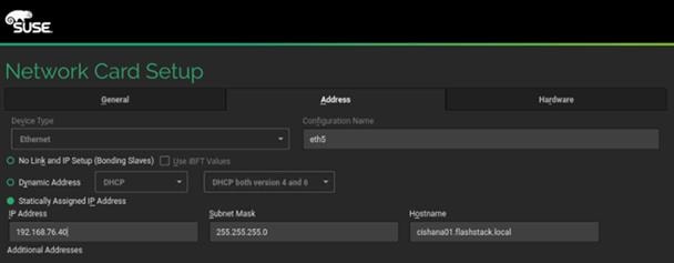
16. Select the Hostname/DNS tab.
17. Provide the server hostname: <var_server01_hostname>
18. Change the Set Hostname via DHCP drop down menu to no.
19. Enter the name server IP: <var_nameserver_ip>
20. Enter the domain name in the domain search field: <var_dns_domain_name>
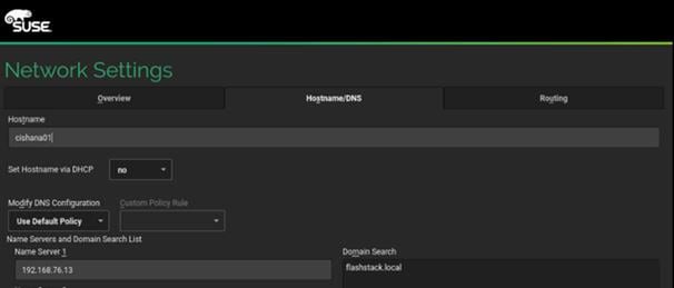
21. Select the Routing tab.
22. Enter the default IPv4 Gateway IP address: <var_os_default_IPv4_gateway> and change the device field to -
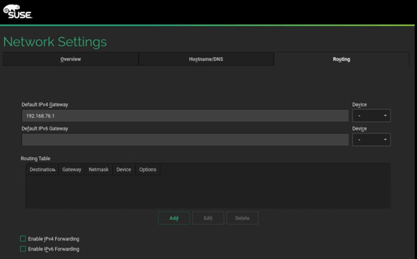
23. Select Next and continue with the SUSE Linux Enterprise installation workflow.
24. When the Add-On Product dialog appears select to install an additional Add-On Product.
25. In the UCS KVM click the virtual media button to UnMap the current ISO image and map the SLE-15-SP1-Packages-x86_64-GM-DVD1.ISO image instead.
26. Select DVD in the Add-On Product dialog and click Next.
27. Choose the Cisco vKCM-Mapped vDVD drive and click Continue.
28. Adapt the module and extension selection to your needs. Recommended modules are:
◦ Basesystem-Module 15.1-0
◦ Desktop-Applications-Module 15.1-0
◦ Legacy-Module 15.1-0
◦ SAP-Applications-Module 15.1-0
◦ SLE-15-SP1-SAP 15.1-0 (Installation medium packages)
◦ SLEHA15SP1 15.1-0 (SUSE Linux Enterprise High Availability Extension)
◦ Server-Applications-Module 15.1-0
29. Continue with the SUSE Linux Enterprise installation workflow.
30. On the Suggested Partitioning dialog select Expert Partitioner and start with the current proposal.
31. Under Hostname > Volume Management delete all volumes
32. Under Hostname > Hard Disks search for the 112G boot LUN.
33. Under Partition Table select Create new partition table.
34. Select GPT as new Partition Table Type and click Next.
35. Change to the Partitions tab and click Add Partition.
36. Select 0.5 GiB as new partition custom size and click Next.
37. Select the Role EFI Boot Partition and click Next.
38. Format the device file system in format type FAT and mount the device at mount point /boot/efi. Click Next.
39. Create another partition and click Add Partition.
40. Select maximum size (111.49 GiB) and click Next.
41. Select the role Raw Volume (unformatted) and click Next.
42. Do not format the device. Keep partition ID Linux LVM and click Next.
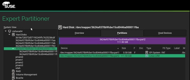
43. Change to Hostname > Volume Management.
44. Add a volume group.
45. Provide the volume group name system. Click Add and then click Next.
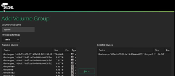
46. Select the system volume group and click Add Logical Volume.
47. Provide the logical volume name swap and keep the normal type selected. Click Next.
48. Select 2 GiB as new logical volume custom size and click Next.
49. Select the swap role and click Next.
50. Select swap for format device filesystem and select the mount point swap. Click Next.
51. Select the system volume group again and click Add Logical Volume.
52. Provide the logical volume name root and keep the normal type selected. Click Next.
53. Select custom size (60 GiB) as new logical volume custom size and click Next.
54. Select the Operating System role and click Next.
55. Select BtrFS for format device filesystem and select the root mount point /. Click Next.
56. Select the system volume group again and click Add Logical Volume.
57. Provide the logical volume name sap and keep the normal type selected. Click Next.
58. Select maximum size (49.48 GiB) as new logical volume custom size and click Next.
59. Select Data and ISV Applications and click Next.
60. Keep the XFS filesystem and mount as /home. Click Next.
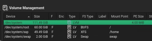
61. Accept the changes and leave the expert partitioner.
62. Click Next to accept the suggested partitioning.
63. Continue with the SUSE Linux Enterprise installation workflow.
64. Provide the system administrator root password <var_os_root_pw> and click Next.
65. Several customization steps are recommended from the Installation Settings screen.
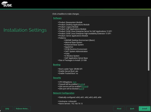
66. Click Software to apply the following changes:
◦ Deselect GNOME Desktop Environment
◦ Select Fonts
◦ Select X Window System.
◦ Select SAP HANA Server Base.
◦ Deselect primary function SAP Application Sever Base.
◦ (Optional) Select primary function high availability
67. Under Security > Firewall will be enabled click Disable.
68. Click Kdump to disable kdump.
69. Set Default system target to text mode.
70. Click Install and follow the SUSE Linux Enterprise installation workflow.
71. Change the ISO image mapping in KVM on installation workflow request.
The server will reboot automatically to finish the installation.
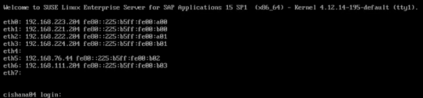
SLES for SAP 15 Post Installation
Apply the post installation steps to prepare the operating system for SAP HANA workload and connect to the SSH server terminal.
Proxy Configuration
Enter and test your proxy configuration:
# yast proxy
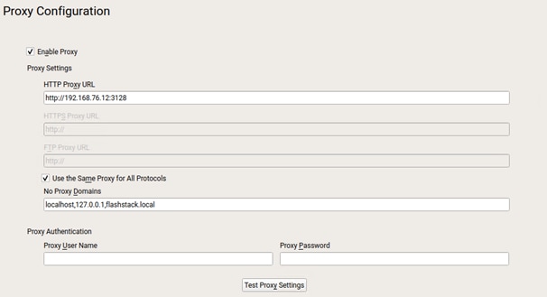
Replace File System Mount Point
1. Create a new mount point /usr/sap:
# mkdir -p /usr/sap
# umount /home
2. Replace the mount point /home with /usr/sap in /etc/fstab and re-mount:
# vi /etc/fstab
/dev/system/sap /usr/sap/ xfs defaults 0 0
# mount -a
Enable System Monitoring
1. Enable system utilization monitoring:
# systemctl enable sysstat
# systemctl start sysstat
2. (Optional) Install rsyslog to bring the /var/log/messages file back:
# zypper in rsyslog
# systemctl enable rsyslog
# systemctl start rsyslog
Additional Software Packages
1. (Optional) Install IPv4 and IPv6 Networking Utilities:
# zypper in iputils
2. Install the NFS client software if required. Mandatory for SAP HANA Scale Out deployments:
# zypper in nfs-utils
3. Install the supportutils and the latest supportconfig:
# zypper in supportutils
Network Configuration
Complete the network interface configuration. If not used, disable IPv6 in the global options tab.
# yast lan
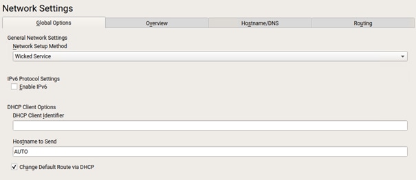
Network Time Configuration
1. Enable NTP and provide one or multiple synchronization server:
# yast ntp-client
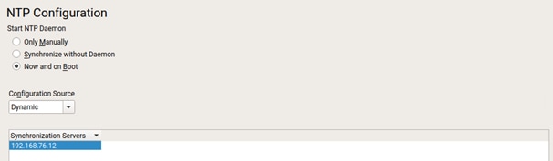
2. Configure the domain name and start the idmap daemon for NFSv4 file system mapping:
# vi /etc/idmapd.conf
[General]
Verbosity = 0
Pipefs-Directory = /var/lib/nfs/rpc_pipe
Domain = flashstack.local
[Mapping]
Nobody-User = nobody
Nobody-Group = nobody
# systemctl start nfs-idmapd
3. Register the product and follow the workflow. Click select extension and review the extension selection still fits to the selection in step 29 of the OS installation. Select missing extensions and click Next.
# yast register
4. From the command line apply the current software patches:
# zypper update
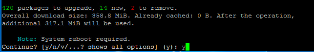
5. Reboot the system.
Disable OS-based Memory Error Monitoring
Linux supports two features related to error monitoring and logging. EDAC (Error Detection and Correction) and mcelog. Both are common in most recent Linux distributions. Cisco recommends disabling EDAC-based error collection, to allow all error reporting to be handled in firmware.
EDAC can be disabled by adding the option “edac_report=off” to the kernel command line. Mcelog is enabled by default in most recent Linux distributions.
For customers who prefer to collect all diagnostic and fault information from OS resident tools mcelog is recommended. In this case Cisco recommends disabling CMCI to prevent performance impact. Firmware logs may be incomplete when OS logging is enabled.
Update Cisco fnic/enic Drivers
Based on the serer type/model, processor version, OS release and version information download the firmware bundle corresponding to the UCS Server firmware installed from the Cisco UCS Hardware and Software Compatibility site.
To update the Cisco fnic/enic drivers, follow these steps:
1. Extract the rpm files of the fnic and enic driver from the driver bundle and copy them to the server.
2. Verify the current driver:
# cat /sys/module/enic/version
2.3.0.53
# cat /sys/module/fnic/version
1.6.0.34
3. RPM install the drivers:
rpm -ivh cisco-enic-usnic-kmp-default-4.0.0.8_k4.12.14_195-802.24.x86_64.rpm
rpm -ivh cisco-fnic-kmp-default-2.0.0.60-141.0.x86_64.rpm
4. Reboot the server:
5. Verify the driver installation after the reboot:
# cat /sys/module/enic/version
4.0.0.8-802.24
# cat /sys/module/fnic/version
2.0.0.60-141.0
Pure Storage UDEV Rule Configuration
Configure the kernel device manager. The most important parameters to be changed are nr_requests and scheduler. Create a rule set for the Pure Storage FlashArray//X:
# vi /etc/udev/rules.d/99-pure-storage.rules
# Recommended settings for Pure Storage FlashArray.
# Use none scheduler for high-performance solid-state storage
ACTION=="add|change", KERNEL=="sd*[!0-9]", SUBSYSTEM=="block", ENV{ID_VENDOR}=="PURE", ATTR{queue/scheduler}="none"
ACTION=="add|change", KERNEL=="dm-[0-9]*", SUBSYSTEM=="block", ENV{DM_NAME}=="3624a937*", ATTR{queue/scheduler}="none"
# Reduce CPU overhead due to entropy collection
ACTION=="add|change", KERNEL=="sd*[!0-9]", SUBSYSTEM=="block", ENV{ID_VENDOR}=="PURE", ATTR{queue/add_random}="0"
ACTION=="add|change", KERNEL=="dm*[!0-9]", SUBSYSTEM=="block", ENV{DM_NAME}=="3624a937*", ATTR{queue/add_random}="0"
# Spread CPU load by redirecting completions to originating CPU
ACTION=="add|change", KERNEL=="sd*[!0-9]", SUBSYSTEM=="block", ENV{ID_VENDOR}=="PURE", ATTR{queue/rq_affinity}="2"
ACTION=="add|change", KERNEL=="dm*[!0-9]", SUBSYSTEM=="block", ENV{DM_NAME}=="3624a937*", ATTR{queue/rq_affinity}="2"
# set HANA devices to be 512kB rather than 4MB max size
ACTION=="add|change", KERNEL=="sd*[!0-9]", SUBSYSTEM=="block", ENV{ID_VENDOR}=="PURE", ATTR{queue/max_sectors_kb}="512"
ACTION=="add|change", KERNEL=="dm-[0-9]*", SUBSYSTEM=="block", ENV{DM_NAME}=="3624a937*", ATTR{queue/max_sectors_kb}="512"
# Set the HBA timeout to 60 seconds
ACTION=="add|change", KERNEL=="sd*[!0-9]", SUBSYSTEM=="block", ENV{ID_VENDOR}=="PURE", ATTR{device/timeout}="60"
Set DM devices number of requests to 1024
ACTION=="add|change", KERNEL=="dm-[0-9]*", SUBSYSTEM=="block", ENV{DM_NAME}=="3624a937*", ATTR{queue/nr_requests}="1024"
DM-Multipath Configuration
Multipathing needs to be setup to do group_by_prio to separate traffic into ALUA priority groups for all PURE LUNs. Create a /etc/multipath.conf configuration file:
# vi /etc/multipath.conf
defaults {
polling_interval 10
}
blacklist {
devnode "^(pmem)[0-9]*"
}
devices {
device {
vendor "PURE"
product "FlashArray"
path_grouping_policy group_by_prio
path_selector "queue-length 0"
path_checker "tur"
features "0"
hardware_handler "1 alua"
prio "const"
failback "immediate"
fast_io_fail_tmo 10
dev_loss_tmo 60
}
}
Setting the Disk Scheduler
The recommended IO scheduler starting with RHEL 8.1 is “none” instead of “noop”.
# yast bootloader and add the kernel parameters “scsi_mod.use_blk_mq=1 dm_mod.use_blk_mq=y”
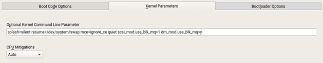
# grub2-mkconfig -o /boot/efi/EFI/sles/grub.cfg
# reboot
Verify the scheduler is set to none:
# cat /sys/block/sda/queue/scheduler
[none] mq-deadline kyber bfq
System Tuning for SAP
List all available solutions to tune the SAP system and apply the one that is appropriate:
# saptune solution list
All solutions (* denotes enabled solution, O denotes override file exists for solution, D denotes deprecated solutions):
BOBJ - 941735 1771258 2578899 SAP_BOBJ
HANA - 941735 1771258 1980196 2578899 2684254 2382421 2534844
D MAXDB - 941735 1771258 2578899
NETWEAVER - 941735 1771258 2578899
NETWEAVER+HANA - 941735 1771258 1980196 2578899 2684254 2382421 2534844
S4HANA-APP+DB - 941735 1771258 1980196 2578899 2684254 2382421 2534844
S4HANA-APPSERVER - 941735 1771258 2578899
S4HANA-DBSERVER - 941735 1771258 1980196 2578899 2684254 2382421 2534844
SAP-ASE - 941735 1410736 1680803 1771258 2578899
Simulate the solution to apply and verify the output regarding any errors:
# saptune solution simulate HANA
Apply the solution and reboot the server:
# saptune solution apply HANA
# saptune daemon start
# reboot
Network Interface Configuration
To complete the network interface configuration, follow these steps:
1. Identify the Ethernet device to vNIC interface mapping first from the Cisco UCS Manager:
a. In the Navigation pane of UCSM, click Servers
b. Select Service Profile > root > Sub-Organizations > HANA > HANA-Server01
c. In the network tab, scroll down to the vNIC section and list the vNICs with their MAC addresses
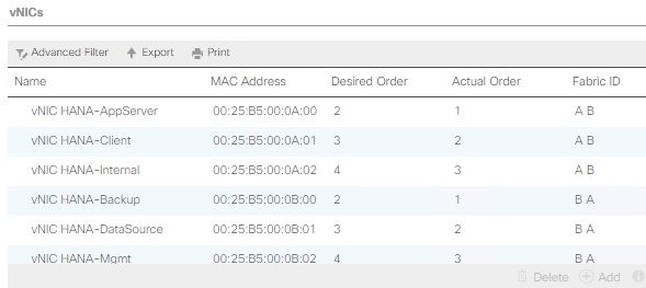
2. Configure the network interfaces:
# yast lan
3. In the SUSE network settings screen, find the network interface with the same MAC address and click edit to provide the appropriate IP address matching to the correct VLAN and provide a fully qualified hostname.
4. Verify all interfaces come up successfully:
# ip link show | egrep 'state|eth[:digit]' | tail -n +2
2: eth0: <BROADCAST,MULTICAST,UP,LOWER_UP> mtu 9000 qdisc mq state UP mode DEFAULT group default qlen 1000
3: eth1: <BROADCAST,MULTICAST,UP,LOWER_UP> mtu 9000 qdisc mq state UP mode DEFAULT group default qlen 1000
4: eth2: <BROADCAST,MULTICAST,UP,LOWER_UP> mtu 9000 qdisc mq state UP mode DEFAULT group default qlen 1000
5: eth3: <BROADCAST,MULTICAST,UP,LOWER_UP> mtu 9000 qdisc mq state UP mode DEFAULT group default qlen 1000
6: eth4: <BROADCAST,MULTICAST,UP,LOWER_UP> mtu 9000 qdisc mq state UP mode DEFAULT group default qlen 1000
7: eth5: <BROADCAST,MULTICAST,UP,LOWER_UP> mtu 1500 qdisc mq state UP mode DEFAULT group default qlen 1000
SAP HANA Persistent Storage Configuration
To verify the multipath devices are listed, follow these steps. Eventually you will be required to rescan the bus.
1. (optional) # rescan-scsi-bus.sh:
# multipath -ll
3624a9370b9fcbe15cd0446a000011fa5 dm-3 PURE,FlashArray
size=512G features='0' hwhandler='1 alua' wp=rw
`-+- policy='round-robin 0' prio=50 status=active
|- 7:0:0:3 sdd 8:48 active ready running
|- 8:0:0:3 sdp 8:240 active ready running
|- 7:0:1:3 sdg 8:96 active ready running
|- 8:0:1:3 sds 65:32 active ready running
|- 7:0:2:3 sdj 8:144 active ready running
|- 8:0:2:3 sdv 65:80 active ready running
|- 7:0:3:3 sdm 8:192 active ready running
`- 8:0:3:3 sdy 65:128 active ready running
3624a9370b9fcbe15cd0446a000011fa4 dm-2 PURE,FlashArray
size=1.5T features='0' hwhandler='1 alua' wp=rw
`-+- policy='round-robin 0' prio=50 status=active
|- 7:0:0:2 sdc 8:32 active ready running
|- 8:0:0:2 sdo 8:224 active ready running
|- 7:0:1:2 sdf 8:80 active ready running
|- 8:0:1:2 sdr 65:16 active ready running
|- 7:0:2:2 sdi 8:128 active ready running
|- 8:0:2:2 sdu 65:64 active ready running
|- 7:0:3:2 sdl 8:176 active ready running
`- 8:0:3:2 sdx 65:112 active ready running
2. Construct and an XFS file system on both multipath devices:
# mkfs.xfs -f /dev/mapper/3624a9370b9fcbe15cd0446a000011fa5
# mkfs.xfs -f /dev/mapper/3624a9370b9fcbe15cd0446a000011fa4
![]() If applicable, construct an XFS file system on the local HANA shared volume.
If applicable, construct an XFS file system on the local HANA shared volume.
3. Create directories for the SAP HANA data, log, and shared file systems:
# mkdir -p /hana/data
# mkdir -p /hana/log
# mkdir -p /hana/shared
4. Persist all mount points and add them to the /etc/fstab file. Mount the volumes afterwards:
# cat /etc/fstab
…
/dev/mapper/3624a9370b9fcbe15cd0446a000011fa5 /hana/log xfs nobarrier,noatime,nodiratime,logbufs=8,logbsize=256k,async,swalloc,allocsize=72k
/dev/mapper/3624a9370b9fcbe15cd0446a000011fa4 /hana/data xfs nobarrier,noatime,nodiratime,logbufs=8,logbsize=256k,async,swalloc,allocsize=72k
192.168.111.26:/hanashared /hana/shared nfs defaults 0 0
# mount -a
5. Verify the information in /etc/hosts is correct:
# cat /etc/hosts
127.0.0.1 localhost
# special IPv6 addresses
::1 localhost ipv6-localhost ipv6-loopback
fe00::0 ipv6-localnet
ff00::0 ipv6-mcastprefix
ff02::1 ipv6-allnodes
ff02::2 ipv6-allrouters
ff02::3 ipv6-allhosts
# AppServer network
192.168.223.200 cishana01a.flashstack.local cishana01a
# Backup network
192.168.221.200 cishana01b.flashstack.local cishana01b
# Client network
192.168.222.200 cishana01c.flashstack.local cishana01c
# DataSource network
192.168.224.200 cishana01d.flashstack.local cishana01d
# Internal internode network
192.168.220.200 cishana01i.flashstack.local cishana01i
# Management network
192.168.76.41 cishana01.flashstack.local cishana01
# NFS HANA shared network
192.168.111.200 cishana01s.flashstack.local cishana01s
# Replication Network
192.168.225.200 cishana01r.flashstack.local cishana01r
Persistent Memory Configuration
Configure and manage Intel Optane DC PMM from the command line with the ipmctl and ndctl utilities. The tools are not installed by default but required to manage the libnvdimm (non-volatile memory device) sub-system in the Linux kernel.
To open an SSH prompt as root to install the host tools, follow these steps:
1. Install the ipmctl host utility:
# zypper in ipmctl
2. Install the ndctl utility:
# zypper in ndctl
3. Verify the persistent memory modules have been discovered and the software can communicate with them:
# ipmctl show -dimm
DimmID | Capacity | HealthState | ActionRequired | LockState | FWVersion
==============================================================================
0x0011 | 252.4 GiB | Healthy | 0 | Disabled | 01.02.00.5435
0x0021 | 252.4 GiB | Healthy | 0 | Disabled | 01.02.00.5435
0x0001 | 252.4 GiB | Healthy | 0 | Disabled | 01.02.00.5435
0x0111 | 252.4 GiB | Healthy | 0 | Disabled | 01.02.00.5435
0x0121 | 252.4 GiB | Healthy | 0 | Disabled | 01.02.00.5435
0x0101 | 252.4 GiB | Healthy | 0 | Disabled | 01.02.00.5435
0x1011 | 252.4 GiB | Healthy | 0 | Disabled | 01.02.00.5435
0x1021 | 252.4 GiB | Healthy | 0 | Disabled | 01.02.00.5435
0x1001 | 252.4 GiB | Healthy | 0 | Disabled | 01.02.00.5435
0x1111 | 252.4 GiB | Healthy | 0 | Disabled | 01.02.00.5435
0x1121 | 252.4 GiB | Healthy | 0 | Disabled | 01.02.00.5435
0x1101 | 252.4 GiB | Healthy | 0 | Disabled | 01.02.00.5435
0x2011 | 252.4 GiB | Healthy | 0 | Disabled | 01.02.00.5435
0x2021 | 252.4 GiB | Healthy | 0 | Disabled | 01.02.00.5435
0x2001 | 252.4 GiB | Healthy | 0 | Disabled | 01.02.00.5435
0x2111 | 252.4 GiB | Healthy | 0 | Disabled | 01.02.00.5435
0x2121 | 252.4 GiB | Healthy | 0 | Disabled | 01.02.00.5435
0x2101 | 252.4 GiB | Healthy | 0 | Disabled | 01.02.00.5435
0x3011 | 252.4 GiB | Healthy | 0 | Disabled | 01.02.00.5435
0x3021 | 252.4 GiB | Healthy | 0 | Disabled | 01.02.00.5435
0x3001 | 252.4 GiB | Healthy | 0 | Disabled | 01.02.00.5435
0x3111 | 252.4 GiB | Healthy | 0 | Disabled | 01.02.00.5435
0x3121 | 252.4 GiB | Healthy | 0 | Disabled | 01.02.00.5435
0x3101 | 252.4 GiB | Healthy | 0 | Disabled | 01.02.00.5435
4. Add a UDEV rule:
# vi /etc/udev/rules.d/60-persistent-storage.rules
# PMEM devices
KERNEL=="pmem*", ENV{DEVTYPE}=="disk", ATTRS{uuid}=="?*", SYMLINK+="disk/by-id/pmem-$attr{uuid}"
5. Create the goal:
# ipmctl create -goal MemoryMode=0 PersistentMemoryType=AppDirect Reserved=0
The following configuration will be applied:
SocketID | DimmID | MemorySize | AppDirect1Size | AppDirect2Size
==================================================================
0x0000 | 0x0011 | 0.0 GiB | 252.0 GiB | 0.0 GiB
0x0000 | 0x0021 | 0.0 GiB | 252.0 GiB | 0.0 GiB
0x0000 | 0x0001 | 0.0 GiB | 252.0 GiB | 0.0 GiB
0x0000 | 0x0111 | 0.0 GiB | 252.0 GiB | 0.0 GiB
0x0000 | 0x0121 | 0.0 GiB | 252.0 GiB | 0.0 GiB
0x0000 | 0x0101 | 0.0 GiB | 252.0 GiB | 0.0 GiB
0x0001 | 0x1011 | 0.0 GiB | 252.0 GiB | 0.0 GiB
0x0001 | 0x1021 | 0.0 GiB | 252.0 GiB | 0.0 GiB
0x0001 | 0x1001 | 0.0 GiB | 252.0 GiB | 0.0 GiB
0x0001 | 0x1111 | 0.0 GiB | 252.0 GiB | 0.0 GiB
0x0001 | 0x1121 | 0.0 GiB | 252.0 GiB | 0.0 GiB
0x0001 | 0x1101 | 0.0 GiB | 252.0 GiB | 0.0 GiB
0x0002 | 0x2011 | 0.0 GiB | 252.0 GiB | 0.0 GiB
0x0002 | 0x2021 | 0.0 GiB | 252.0 GiB | 0.0 GiB
0x0002 | 0x2001 | 0.0 GiB | 252.0 GiB | 0.0 GiB
0x0002 | 0x2111 | 0.0 GiB | 252.0 GiB | 0.0 GiB
0x0002 | 0x2121 | 0.0 GiB | 252.0 GiB | 0.0 GiB
0x0002 | 0x2101 | 0.0 GiB | 252.0 GiB | 0.0 GiB
0x0003 | 0x3011 | 0.0 GiB | 252.0 GiB | 0.0 GiB
0x0003 | 0x3021 | 0.0 GiB | 252.0 GiB | 0.0 GiB
0x0003 | 0x3001 | 0.0 GiB | 252.0 GiB | 0.0 GiB
0x0003 | 0x3111 | 0.0 GiB | 252.0 GiB | 0.0 GiB
0x0003 | 0x3121 | 0.0 GiB | 252.0 GiB | 0.0 GiB
0x0003 | 0x3101 | 0.0 GiB | 252.0 GiB | 0.0 GiB
Do you want to continue? [y/n]
6. Confirm with Y and reboot the server to apply the new memory allocations.
7. Verify regions have been created:
# ipmctl show -region
SocketID | ISetID | Persistent | Capacity | FreeCapacity | HealthState
| | MemoryType | | |
=================================================================================
0x0000 | 0xd7d..9c2ccc | AppDirect | 1512.0 GiB | 1512.0 GiB | Healthy
0x0001 | 0xfba..9b2ccc | AppDirect | 1512.0 GiB | 1512.0 GiB | Healthy
0x0002 | 0xc67..af2ccc | AppDirect | 1512.0 GiB | 1512.0 GiB | Healthy
0x0003 | 0x685..9f2ccc | AppDirect | 1512.0 GiB | 1512.0 GiB | Healthy
8. Create a name space for each region; on a 4-socket server invoke the command four times:
# ndctl create-namespace
9. Verify the namespace has been created successfully:
# ndctl list
[
{
"dev":"namespace1.0",
"mode":"fsdax",
"map":"dev",
"size":1598128390144,
"uuid":"81257c85-4410-4def-8dba-3c120943c6b7",
"sector_size":512,
"align":2097152,
"blockdev":"pmem1"
},
{
"dev":"namespace3.0",
"mode":"fsdax",
"map":"dev",
"size":1598128390144,
"uuid":"197dc10f-cd0d-4a84-bba3-f104df3e70be",
"sector_size":512,
"align":2097152,
"blockdev":"pmem3"
},
{
"dev":"namespace0.0",
"mode":"fsdax",
"map":"dev",
"size":1598128390144,
"uuid":"23526924-74bf-4bab-8fd9-27be6190ce56",
"sector_size":512,
"align":2097152,
"blockdev":"pmem0"
},
{
"dev":"namespace2.0",
"mode":"fsdax",
"map":"dev",
"size":1598128390144,
"uuid":"5847f6d4-4a3d-447c-b299-7d0e38c1dcdd",
"sector_size":512,
"align":2097152,
"blockdev":"pmem2"
}
]
10. Construct an XFS file system on the block devices:
# for i in {0..3}; do mkfs.xfs -f -d su=2m,sw=1 -m reflink=0 /dev/pmem$i; done
11. Create directories and mount the block devices using the DAX file system option:
# for i in {0..3}; do mkdir -p /hana/pmem/nvmem$i; done
# for i in {0..3}; do mount -t xfs -o dax,lazytime /dev/pmem0 /hana/pmem/nvmem$i; done
12. Change the permission of the mount points:
# chmod 755 /hana/pmem/nvmem*
# chown <SID>adm:sapsys /hana/pmem/nvmem*
13. Add the mount points to /etc/fstab to persist them:
# vi /etc/fstab
/dev/pmem0 /hana/pmem/nvmem0 xfs dax,lazytime 1 2
/dev/pmem1 /hana/pmem/nvmem1 xfs dax,lazytime 1 2
/dev/pmem2 /hana/pmem/nvmem2 xfs dax,lazytime 1 2
/dev/pmem3 /hana/pmem/nvmem3 xfs dax,lazytime 1 2
The device names chosen by the kernel are subject to creation order and discovery. For static configuration they usually don’t change, alternatively consider using persistent naming instead to mount the pmem namespace.
# ls -l /dev/disk/by-id/pmem*
lrwxrwxrwx 1 root root 11 Oct 29 15:34 /dev/disk/by-id/pmem-39afa860-5b33-4956-a1ec-1c176cf34608 -> ../../pmem2
lrwxrwxrwx 1 root root 11 Oct 29 15:34 /dev/disk/by-id/pmem-76c312d8-86e0-4f3d-b630-b816f95f4ff8 -> ../../pmem1
lrwxrwxrwx 1 root root 11 Oct 29 15:34 /dev/disk/by-id/pmem-af000a5b-14ac-4f49-a919-c89bc462944d -> ../../pmem3
lrwxrwxrwx 1 root root 11 Oct 29 15:34 /dev/disk/by-id/pmem-df203ae8-13ef-4b65-bd2e-c7f95979493a -> ../../pmem0
The persistent name for a pmem namespace in /etc/fstab will look like the following:
/dev/disk/by-id/pmem-df203ae8-13ef-4b65-bd2e-c7f95979493a /hana/pmem/nvmem0 xfs dax,lazytime 1 2
RHEL 8 for SAP Solutions
Red Hat Enterprise Linux 8 (RHEL) for SAP Solutions is the reference platform for the software deployment of SAP. It is optimized for SAP applications like SAP HANA. Install the operating system as described in the standard RHEL installation guide. This section lists where the lab installation deviates from the installation workflow.
The following supplement RHEL information is available from the SAP notes system:
● SAP Note 2526952 - Red Hat Enterprise Linux for SAP Solutions
● SAP Note 2772999 - Red Hat Enterprise Linux 8.x: Installation and Configuration
● SAP Note 2777782 - SAP HANA DB: Recommended OS Settings for RHEL 8
RHEL for SAP Solutions Installation
Download the standard RHEL ISO image from https://access.redhat.com/downloads and map the installation ISO image in the KVM console:
1. In the Navigation pane of the Cisco UCS Manager, click Servers.
2. Select Service Profile > root > Sub-Organization > HANA > HANA-Server04.
3. In the Actions section click KVM Console.
4. Choose Virtual Media > Activate Virtual Devices.
5. For Unencrypted Virtual Media Session, select Accept this Session and then click Apply.
6. Click Virtual Media and choose Map CD/DVD.
7. Click Browse to navigate to the ISO media location. Select rhel-8.0-x86_64.ISO. Click Open.
8. Click Map Device.
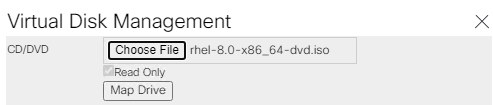
9. In the KVM Console menu, click Boot Server.
10. During the VIC FC boot driver verification at the server boot time the Pure Storage FlashArray//X target WWPN numbers are listed during the connection verification.
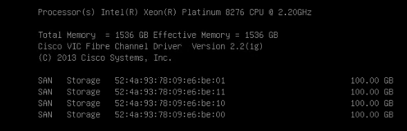
The system will automatically boot from the ISO image into the installation wizard.
11. Select Install Red Hat Enterprise Linux 8.0.0 to start the interactive installation process using the server base installation option.
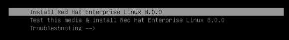
12. The installation summary page appears. Complete all items before starting the installation.
13. Select Software Selection and use the “Server” Base Environment. No Add-Ons are required during installation. Click Done to return to the main screen.
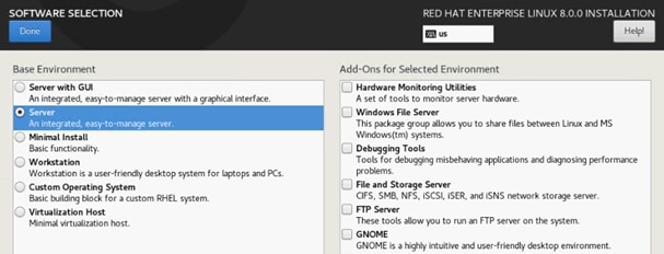
14. Select Time & Date. Select the timezone of your choice and ensure the date and time are set correct.
15. Select Installation Destination and Add a disk.
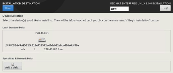
16. Select the 100 GB boot LUN created before. Click Done.
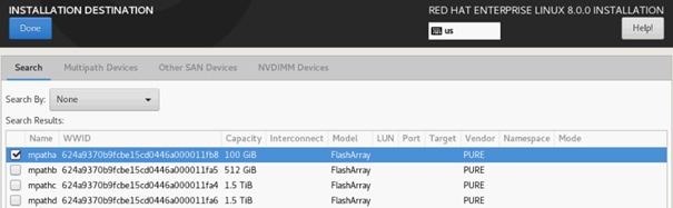
17. Change the radio button Storage Configuration to Custom. Click Done.
18. Click the link to create the file system layout automatically.
19. Delete the home file system pressing the - button.
20. Select the root volume and resize to 94.4 GiB. Click Done.
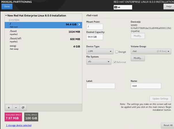
21. Uncheck Enable KDump.
22. Select Network & Host Name.
a. Enter a short host name (cishana04) and click Apply.
b. Identify the Ethernet device to vNIC interface mapping first from the Cisco UCS Manager.
i. In the Navigation pane of UCSM, click Servers
ii. Select Service Profile > root > Sub-Organizations > HANA > HANA-Server04
iii. In the network tab, scroll down to the vNIC section and list the vNICs with their MAC addresses
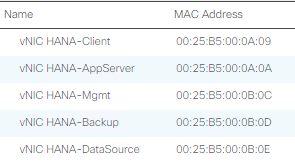
c. Compare the Ethernet hardware addresses and configure the network interfaces
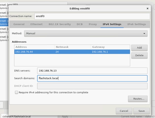
23. Switch the interfaces On and click Done.
24. Select System Purpose Role: Red Hat Enterprise Linux Server and the appropriate SLA and usage information. Click Done.
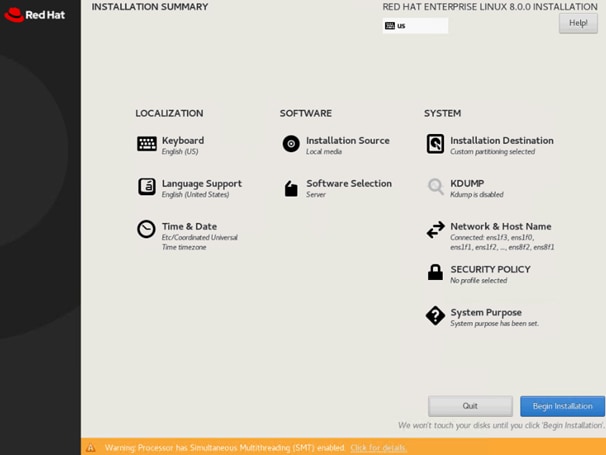
25. Click Begin Installation and provide a root password while the installation is running in the background.
26. Before rebooting, unmap the ISO image from the KVM console.
RHEL for SAP Solutions Post Installation
Proxy Configuration
Multiple configuration files to configure a system wide proxy exist. Open an SSH terminal and edit the following configuration files to setup a permanent proxy configuration.
# echo "export http_proxy=http://proxy.example.com:3128/" > /etc/profile.d/http_proxy.sh
# echo "setenv http_proxy http://proxy.example.com:3128/" > /etc/profile.d/http_proxy.csh
Attach a proxy configuration line to the YUM configuration:
# echo "proxy=http://proxy.example.com:3128" >> /etc/yum.conf
Configure a proxy for the subscription-manager:
# vi /etc/rhsm/rhsm.conf
proxy_hostname=proxy.example.com
proxy_port=3128
Configure a proxy for the rhn-register and up2date services:
# vi /etc/sysconfig/rhn/up2date
EnableProxy=1
httpProxy=proxy.example.com:3128
Enable Access to Red Hat Software Updates
Register the system on the Red Hat Customer Portal or a local Red Hat Satellite server to retrieve update packages. It is recommended to update all packages (including kernel and glibc) to the latest version available and certified to run SAP HANA workload after the initial OS installation and at regular intervals in the future.
Follow the Red Hat documentation (https://access.redhat.com/solutions/4714781) to subscribe the SAP HANA system to the Update Services for SAP Solutions.
# subscription-manager register --username <username> --password <password>
# subscription-manager role --set="Red Hat Enterprise Linux Server"
# subscription-manager service-level --set="Standard"
# subscription-manager usage --set="Development/Test"
# subscription-manager attach
# subscription-manager repos --disable="*"
# subscription-manager repos --enable="rhel-8-for-x86_64-baseos-e4s-rpms" --enable="rhel-8-for-x86_64-appstream-e4s-rpms" --enable="rhel-8-for-x86_64-sap-solutions-e4s-rpms" --enable="rhel-8-for-x86_64-sap-netweaver-e4s-rpms"
# subscription-manager release --set=8.1
Validate the System Purpose had been set:
# syspurpose show
{
"role": "Red Hat Enterprise Linux Server",
"service_level_agreement": "Self-Support",
"usage": "Development/Test"
}
System purpose successfully sent to subscription management server.
Additional Software Packages
Install additional software packages required by all SAP products and SAP HANA:
# yum -y install uuidd libnsl tcsh psmisc nfs-utils bind-utils python2
# yum -y install expect graphviz iptraf-ng krb5-workstation libatomic libcanberra-gtk2 libibverbs libicu libpng12 libssh2 lm_sensors numactl PackageKit-gtk3-module xorg-x11-xauth compat-sap-c++-9
# yum group install Server
Apply Security Patches
Apply the most recent security patches immediately after the RHEL installation completes and disable SELinux which can conflict with several components of an SAP server environment like the installation tools.
# yum -y update
# sed -i 's/\(SELINUX=enforcing\|SELINUX=permissive\)/SELINUX=disabled/g' /etc/selinux/config
# reboot
Python Configuration
The SAP HANA installer fails to execute the python interpreter if alternatives are not set.
# alternatives --set python /usr/bin/python2
Firewall Configuration
To avoid problems with the firewall during installation, disable it completely. To protect your SAP HANA server from unauthorized access, configure the built-in firewall of the RHEL system to only allow access via the ports which the SAP software uses for communication.
# systemctl stop firewalld
# systemctl disable firewalld
Disable Core Dumps and kdump, Configure File Handles and Processes
All crashes of SAP HANA are typically analyzed by SAP support, so they do not rely on operating system mechanisms for crash reporting. To avoid delays when a Linux kernel crash or a core dump occurs, disable the application crash and core file handling of the operating system.
Some components (for example, the SAP J2EE engine, Oracle RDBMS software, and so on) need to keep many file handles opened simultaneously. The RHEL 8 default of 1024 is too small in certain cases. In addition, some components need to create a higher amount of processes per user from time to time, which might exceed the default maximum allowed number of processes per user on RHEL 8.
# vi /etc/security/limits.d/99-sap.conf
* soft core 0
* hard core 0
@sapsys hard nofile 65536
@sapsys soft nofile 65536
@sapsys hard nproc unlimited
@sapsys soft nproc unlimited
Disable the kernel crash dump facility:
# systemctl stop kdump
# systemctl disable kdump
Hostname Configuration
Use the command hostname -s to display the short hostname and hostname -f to display the long, full qualified hostname.
Add the full qualified hostname to the /etc/hosts file:
# vi /etc/hosts
127.0.0.1 localhost
# special IPv6 addresses
::1 localhost ipv6-localhost ipv6-loopback
fe00::0 ipv6-localnet
ff00::0 ipv6-mcastprefix
ff02::1 ipv6-allnodes
ff02::2 ipv6-allrouters
ff02::3 ipv6-allhosts
# AppServer network
192.168.223.200 cishana01a.flashstack.local cishana01a
# Backup network
192.168.221.200 cishana01b.flashstack.local cishana01b
# Client network
192.168.222.200 cishana01c.flashstack.local cishana01c
# DataSource network
192.168.224.200 cishana01d.flashstack.local cishana01d
# Internal internode network
192.168.220.200 cishana01i.flashstack.local cishana01i
# Management network
192.168.76.41 cishana01.flashstack.local cishana01
# NFS HANA shared network
192.168.111.200 cishana01s.flashstack.local cishana01s
# Replication Network
192.168.225.200 cishana01r.flashstack.local cishana01r
Add any additional full qualified hostname to the /etc/hosts file as well, like for the application, client, backup, datasource or replication network.
Network Configuration
Ensure the network devices configured during installation will be enabled during boot. The following command will change the ONBOOT variable in line 15 of the network configuration file to yes. Verify the successful change.
# sed -i "15s/no/yes/" /etc/sysconfig/network-scripts/ifcfg-ens*
# grep ONBOOT /etc/sysconfig/network-scripts/ifcfg-ens*
Review Network Time and Date Configuration
During the installation a local NTP server was configured. Review the configuration is working.
# vi /etc/chrony.conf
# Use public servers from the pool.ntp.org project.
# Please consider joining the pool (http://www.pool.ntp.org/join.html).
# pool 2.rhel.pool.ntp.org iburst
server 192.168.76.12 iburst
Restart the chronyd service:
# systemctl restart chronyd
# systemctl enable chronyd
Validate the service is running and connected to the local time server:
# chronyc sources
210 Number of sources = 1
MS Name/IP address Stratum Poll Reach LastRx Last sample
===============================================================================
^* 192.168.76.12 2 6 17 36 +607ns[ -113us] +/- 1549us
Configure Linux Kernel Parameter
Increase some Linux kernel parameters to meet the requirements of the SAP HANA software:
# vi /etc/sysctl.d/sap.conf
# SAP settings
vm.max_map_count = 2147483647
kernel.pid_max = 4194304
# SAP Note 2382421 - Optimizing the Network Configuration
net.core.somaxconn = 4096
net.ipv4.tcp_max_syn_backlog = 8192
net.ipv4.tcp_slow_start_after_idle = 0
Configure systemd tmpfiles
Ensure important lock files and sockets in /tmp will not be deleted by systemd-tmpfiles:
# vi /etc/tmpfiles.d/sap.conf
# systemd.tmpfiles exclude file for SAP
# SAP software stores some important files in /tmp which should not be deleted automatically
# Exclude SAP socket and lock files
x /tmp/.sap*
# Exclude HANA lock file
x /tmp/.hdb*lock
# Exclude TREX lock file
x /tmp/.trex*lock
Configure Tuned to Use SAP-HANA Profile
The tuned profile "sap-hana" provided by Red Hat as part of the RHEL for SAP Solutions subscription, contains many required settings and configurations for SAP HANA. Therefore the "sap-hana" tuned profile must be activated on all systems running SAP HANA.
Use the following commands to install and activate the tuned profile "sap-hana" and check if it is active:
# yum -y install tuned-profiles-sap-hana
# systemctl start tuned
# systemctl enable tuned
# tuned-adm profile sap-hana
# tuned-adm active
Current active profile: sap-hana
Update Cisco fnic/enic drivers
Based on the serer type/model, processor version, OS release and version information download the firmware bundle corresponding to the UCS Server firmware installed from the Cisco UCS Hardware and Software Compatibility site.
To extract the rpm files of the fnic and enic driver from the driver bundle and copy them to the server, follow these steps:
1. Verify the current driver:
# cat /sys/module/enic/version
2.3.0.53
# cat /sys/module/fnic/version
1.6.0.47
2. RPM install the drivers:
rpm -ivh kmod-enic-4.0.0.8-802.24.rhel8u1.x86_64.rpm
rpm -ivh kmod-fnic-2.0.0.60-141.0.rhel8u1.x86_64.rpm
3. Reboot the server:
4. Verify the driver installation after the reboot:
# cat /sys/module/enic/version
4.0.0.8-802.24
# cat /sys/module/fnic/version
2.0.0.60-141.0
Pure Storage UDEV Rule Configuration
Configure the kernel device manager. The most important parameters to be changed are nr_requests and scheduler.
Create a rule set for the Pure Storage FlashArray//X:
# vi /etc/udev/rules.d/99-pure-storage.rules
# Recommended settings for Pure Storage FlashArray.
# Use none scheduler for high-performance solid-state storage
ACTION=="add|change", KERNEL=="sd*[!0-9]", SUBSYSTEM=="block", ENV{ID_VENDOR}=="PURE", ATTR{queue/scheduler}="none"
ACTION=="add|change", KERNEL=="dm-[0-9]*", SUBSYSTEM=="block", ENV{DM_NAME}=="3624a937*", ATTR{queue/scheduler}="none"
# Reduce CPU overhead due to entropy collection
ACTION=="add|change", KERNEL=="sd*[!0-9]", SUBSYSTEM=="block", ENV{ID_VENDOR}=="PURE", ATTR{queue/add_random}="0"
ACTION=="add|change", KERNEL=="dm*[!0-9]", SUBSYSTEM=="block", ENV{DM_NAME}=="3624a937*", ATTR{queue/add_random}="0"
# Spread CPU load by redirecting completions to originating CPU
ACTION=="add|change", KERNEL=="sd*[!0-9]", SUBSYSTEM=="block", ENV{ID_VENDOR}=="PURE", ATTR{queue/rq_affinity}="2"
ACTION=="add|change", KERNEL=="dm*[!0-9]", SUBSYSTEM=="block", ENV{DM_NAME}=="3624a937*", ATTR{queue/rq_affinity}="2"
# set HANA devices to be 512kB rather than 4MB max size
ACTION=="add|change", KERNEL=="sd*[!0-9]", SUBSYSTEM=="block", ENV{ID_VENDOR}=="PURE", ATTR{queue/max_sectors_kb}="512"
ACTION=="add|change", KERNEL=="dm-[0-9]*", SUBSYSTEM=="block", ENV{DM_NAME}=="3624a937*", ATTR{queue/max_sectors_kb}="512"
# Set the HBA timeout to 60 seconds
ACTION=="add|change", KERNEL=="sd*[!0-9]", SUBSYSTEM=="block", ENV{ID_VENDOR}=="PURE", ATTR{device/timeout}="60"
Set DM devices number of requests to 1024
ACTION=="add|change", KERNEL=="dm-[0-9]*", SUBSYSTEM=="block", ENV{DM_NAME}=="3624a937*", ATTR{queue/nr_requests}="1024"
DM-Multipath Configuration
Setup multipathing with group by prio policy for all PURE LUNs:
# vi /etc/multipath.conf
defaults {
find_multipaths yes
user_friendly_names no
polling_interval 10
}
blacklist {
devnode "^(pmem)[0-9]*"
}
devices {
device {
vendor "PURE"
product "FlashArray"
path_grouping_policy group_by_prio
failback "immediate"
fast_io_fail_tmo 10
prio "alua"
hardware_handler "1 alua"
max_sectors_kb 4096
}
}
Set the Disk Scheduler
The recommended IO scheduler starting with RHEL 8.1 is “none” instead of “noop”.
# grubby --default-kernel
/boot/vmlinuz-4.18.0-147.27.1.el8_1.x86_64
# grubby --args="scsi_mod.use_blk_mq=1 dm_mod.use_blk_mq=y" --update-kernel /boot/vmlinuz-4.18.0-147.27.1.el8_1.x86_64
# grubby --info /boot/vmlinuz-4.18.0-147.27.1.el8_1.x86_64
index=0
kernel="/boot/vmlinuz-4.18.0-147.27.1.el8_1.x86_64"
args="ro resume=/dev/mapper/rhel-swap rd.lvm.lv=rhel/root rd.lvm.lv=rhel/swap
rhgb quiet $tuned_params scsi_mod.use_blk_mq=1 dm_mod.use_blk_mq=y"
root="/dev/mapper/rhel-root"
initrd="/boot/initramfs-4.18.0-147.27.1.el8_1.x86_64.img $tuned_initrd"
title="Red Hat Enterprise Linux (4.18.0-147.27.1.el8_1.x86_64) 8.1 (Ootpa)"
# grub2-mkconfig -o /boot/efi/EFI/redhat/grub.cfg
Generating grub configuration file ...
Adding boot menu entry for EFI firmware configuration
Done
# reboot
SAP HANA Persistent Storage Configuration
Verify the multipath devices are listed:
# multipath -ll
3624a9370b9fcbe15cd0446a000011fb2 dm-6 PURE,FlashArray
size=1.0T features='0' hwhandler='1 alua' wp=rw
`-+- policy='service-time 0' prio=50 status=active
|- 1:0:0:4 sde 8:64 active ready running
|- 1:0:1:4 sdi 8:128 active ready running
|- 1:0:2:4 sdm 8:192 active ready running
|- 1:0:3:4 sdq 65:0 active ready running
|- 8:0:0:4 sdu 65:64 active ready running
|- 8:0:1:4 sdy 65:128 active ready running
|- 8:0:2:4 sdac 65:192 active ready running
`- 8:0:3:4 sdag 66:0 active ready running
3624a9370b9fcbe15cd0446a000011fab dm-5 PURE,FlashArray
size=512G features='0' hwhandler='1 alua' wp=rw
`-+- policy='service-time 0' prio=50 status=active
|- 1:0:0:3 sdd 8:48 active ready running
|- 1:0:1:3 sdh 8:112 active ready running
|- 1:0:2:3 sdl 8:176 active ready running
|- 1:0:3:3 sdp 8:240 active ready running
|- 8:0:0:3 sdt 65:48 active ready running
|- 8:0:1:3 sdx 65:112 active ready running
|- 8:0:2:3 sdab 65:176 active ready running
`- 8:0:3:3 sdaf 65:240 active ready running
3624a9370b9fcbe15cd0446a000011faa dm-1 PURE,FlashArray
size=9.0T features='0' hwhandler='1 alua' wp=rw
`-+- policy='service-time 0' prio=50 status=active
|- 1:0:0:2 sdc 8:32 active ready running
|- 1:0:1:2 sdg 8:96 active ready running
|- 1:0:2:2 sdk 8:160 active ready running
|- 1:0:3:2 sdo 8:224 active ready running
|- 8:0:0:2 sds 65:32 active ready running
|- 8:0:1:2 sdw 65:96 active ready running
|- 8:0:2:2 sdaa 65:160 active ready running
`- 8:0:3:2 sdae 65:224 active ready running
Verify the IO scheduler none is set accordingly:
# cat /sys/block/dm-1/queue/scheduler
[none] mq-deadline kyber bfq
Construct and an XFS file system on both multipath devices:
# mkfs.xfs -f /dev/mapper/3624a9370b9fcbe15cd0446a000011fb2
# mkfs.xfs -f /dev/mapper/3624a9370b9fcbe15cd0446a000011fab
# mkfs.xfs -f /dev/mapper/3624a9370b9fcbe15cd0446a000011faa
Create directories for the SAP HANA data, log, and shared file systems:
# mkdir -p /hana/data/<SID>
# mkdir -p /hana/log/<SID>
# mkdir -p /hana/shared
Persist all mount points and add them to the /etc/fstab file. Mount the volumes afterwards:
# cat /etc/fstab
…
/dev/mapper/3624a9370b9fcbe15cd0446a000011fab /hana/log/<SID> xfs inode64 0 0
/dev/mapper/3624a9370b9fcbe15cd0446a000011faa /hana/data/<SID> xfs inode64 0 0
/dev/mapper/3624a9370b9fcbe15cd0446a000011fb2 /hana/shared xfs inode64 0 0
# NFS HANA Shared for SAP HANA Scale Out
#192.168.111.26:/hanashared /hana/shared nfs defaults 0 0
# mount -a
Disable OS-based Memory Error Monitoring
Linux supports two features related to error monitoring and logging. EDAC (Error Detection and Correction) and mcelog. Both are common in most recent Linux distributions. Cisco recommends disabling EDAC based error collection, to allow all error reporting to be handled in firmware.
EDAC can be disabled by adding the option “edac_report=off” to the kernel command line. Mcelog is enabled by default in most recent Linux distributions.
For customers who prefer to collect all diagnostic and fault information from OS resident tools mcelog is recommended. In this case Cisco recommends disabling CMCI to prevent performance impact. Firmware logs may be incomplete when OS logging is enabled.
Configure C-States for Lower Latency in Linux
The Linux kernel shipped with RHEL 8 on the x86_64 platform includes a cpuidle driver for recent Intel CPUs: intel_idle. This driver leads to a different behavior in C-states switching. The normal operating state is C0, when the processor is put to a higher C state, which saves power. For low latency applications, the additional time needed to stop and start the execution of the code again will cause performance degradations. Therefore, it is recommended to limit the C-states to C0 and C1:
# grubby --default-kernel
/boot/vmlinuz-4.18.0-147.27.1.el8_1.x86_64
# grubby --args="processor.max_cstate=1 intel_idle.max_cstate=1" --update-kernel /boot/vmlinuz-4.18.0-147.27.1.el8_1.x86_64
# grubby --info /boot/vmlinuz-4.18.0-147.27.1.el8_1.x86_64
index=0
kernel="/boot/vmlinuz-4.18.0-147.27.1.el8_1.x86_64"
args="ro resume=/dev/mapper/rhel-swap rd.lvm.lv=rhel/root rd.lvm.lv=rhel/swap
rhgb quiet $tuned_params scsi_mod.use_blk_mq=1 dm_mod.use_blk_mq=y
processor.max_cstate=1 intel_idle.max_cstate=1"
root="/dev/mapper/rhel-root"
initrd="/boot/initramfs-4.18.0-147.27.1.el8_1.x86_64.img $tuned_initrd"
title="Red Hat Enterprise Linux (4.18.0-147.27.1.el8_1.x86_64) 8.1 (Ootpa)"
# grub2-mkconfig -o /boot/efi/EFI/redhat/grub.cfg
Generating grub configuration file ...
Adding boot menu entry for EFI firmware configuration
Done
# reboot
Persistent Memory Configuration
Configure and manage Intel Optane DC PMM from the command line with the ipmctl and ndctl utilities. The tools are not installed by default but required to manage the libnvdimm (non-volatile memory device) sub-system in the Linux kernel.
To open an SSH prompt as root to install the host tools, follow these steps:
1. EPEL packages assume that the 'codeready-builder' repository is enabled.
# subscription-manager repos --enable "codeready-builder-for-rhel-8-$(arch)-rpms"
2. Enable the EPEL 8 repository or download the required rpm file from https://dl.fedoraproject.org/pub/epel/8/Everything/x86_64/Packages/.
# yum install https://dl.fedoraproject.org/pub/epel/epel-release-latest-8.noarch.rpm
# yum info ipmctl
# yum -y install ipmctl
3. Install the ndctl utility
# yum -y install ndctl
4. Verify the persistent memory modules have been discovered and the software can communicate with them.
# ipmctl show -dimm
DimmID | Capacity | LockState | HealthState | FWVersion
===============================================================
0x0001 | 252.454 GiB | Disabled | Healthy | 01.02.00.5435
0x0011 | 252.454 GiB | Disabled | Healthy | 01.02.00.5435
0x0021 | 252.454 GiB | Disabled | Healthy | 01.02.00.5435
0x0101 | 252.454 GiB | Disabled | Healthy | 01.02.00.5435
0x0111 | 252.454 GiB | Disabled | Healthy | 01.02.00.5435
0x0121 | 252.454 GiB | Disabled | Healthy | 01.02.00.5435
0x1001 | 252.454 GiB | Disabled | Healthy | 01.02.00.5435
0x1011 | 252.454 GiB | Disabled | Healthy | 01.02.00.5435
0x1021 | 252.454 GiB | Disabled | Healthy | 01.02.00.5435
0x1101 | 252.454 GiB | Disabled | Healthy | 01.02.00.5435
0x1111 | 252.454 GiB | Disabled | Healthy | 01.02.00.5435
0x1121 | 252.454 GiB | Disabled | Healthy | 01.02.00.5435
0x2001 | 252.454 GiB | Disabled | Healthy | 01.02.00.5435
0x2011 | 252.454 GiB | Disabled | Healthy | 01.02.00.5435
0x2021 | 252.454 GiB | Disabled | Healthy | 01.02.00.5435
0x2101 | 252.454 GiB | Disabled | Healthy | 01.02.00.5435
0x2111 | 252.454 GiB | Disabled | Healthy | 01.02.00.5435
0x2121 | 252.454 GiB | Disabled | Healthy | 01.02.00.5435
0x3001 | 252.454 GiB | Disabled | Healthy | 01.02.00.5435
0x3011 | 252.454 GiB | Disabled | Healthy | 01.02.00.5435
0x3021 | 252.454 GiB | Disabled | Healthy | 01.02.00.5435
0x3101 | 252.454 GiB | Disabled | Healthy | 01.02.00.5435
0x3111 | 252.454 GiB | Disabled | Healthy | 01.02.00.5435
0x3121 | 252.454 GiB | Disabled | Healthy | 01.02.00.5435
5. Add a UDEV rule:
# vi /etc/udev/rules.d/60-persistent-storage.rules
# PMEM devices
KERNEL=="pmem*", ENV{DEVTYPE}=="disk", ATTRS{uuid}=="?*", SYMLINK+="disk/by-id/pmem-$attr{uuid}"
6. Create the goal:
# ipmctl create -goal
The following configuration will be applied:
SocketID | DimmID | MemorySize | AppDirect1Size | AppDirect2Size
==================================================================
0x0000 | 0x0001 | 0.000 GiB | 252.000 GiB | 0.000 GiB
0x0000 | 0x0011 | 0.000 GiB | 252.000 GiB | 0.000 GiB
0x0000 | 0x0021 | 0.000 GiB | 252.000 GiB | 0.000 GiB
0x0000 | 0x0101 | 0.000 GiB | 252.000 GiB | 0.000 GiB
0x0000 | 0x0111 | 0.000 GiB | 252.000 GiB | 0.000 GiB
0x0000 | 0x0121 | 0.000 GiB | 252.000 GiB | 0.000 GiB
0x0001 | 0x1001 | 0.000 GiB | 252.000 GiB | 0.000 GiB
0x0001 | 0x1011 | 0.000 GiB | 252.000 GiB | 0.000 GiB
0x0001 | 0x1021 | 0.000 GiB | 252.000 GiB | 0.000 GiB
0x0001 | 0x1101 | 0.000 GiB | 252.000 GiB | 0.000 GiB
0x0001 | 0x1111 | 0.000 GiB | 252.000 GiB | 0.000 GiB
0x0001 | 0x1121 | 0.000 GiB | 252.000 GiB | 0.000 GiB
0x0002 | 0x2001 | 0.000 GiB | 252.000 GiB | 0.000 GiB
0x0002 | 0x2011 | 0.000 GiB | 252.000 GiB | 0.000 GiB
0x0002 | 0x2021 | 0.000 GiB | 252.000 GiB | 0.000 GiB
0x0002 | 0x2101 | 0.000 GiB | 252.000 GiB | 0.000 GiB
0x0002 | 0x2111 | 0.000 GiB | 252.000 GiB | 0.000 GiB
0x0002 | 0x2121 | 0.000 GiB | 252.000 GiB | 0.000 GiB
0x0003 | 0x3001 | 0.000 GiB | 252.000 GiB | 0.000 GiB
0x0003 | 0x3011 | 0.000 GiB | 252.000 GiB | 0.000 GiB
0x0003 | 0x3021 | 0.000 GiB | 252.000 GiB | 0.000 GiB
0x0003 | 0x3101 | 0.000 GiB | 252.000 GiB | 0.000 GiB
0x0003 | 0x3111 | 0.000 GiB | 252.000 GiB | 0.000 GiB
0x0003 | 0x3121 | 0.000 GiB | 252.000 GiB | 0.000 GiB
Do you want to continue? [y/n]
7. Confirm with Y and reboot the server to apply the new memory allocations.
8. Verify regions had been created:
# ipmctl show -region
SocketID | ISetID | Persistent | Capacity | FreeCapacity | HealthState
| | MemoryType | | |
=================================================================================
0x0000 | 0xd7d..9c2ccc | AppDirect | 1512.0 GiB | 1512.0 GiB | Healthy
0x0001 | 0xfba..9b2ccc | AppDirect | 1512.0 GiB | 1512.0 GiB | Healthy
0x0002 | 0xc67..af2ccc | AppDirect | 1512.0 GiB | 1512.0 GiB | Healthy
0x0003 | 0x685..9f2ccc | AppDirect | 1512.0 GiB | 1512.0 GiB | Healthy
9. Create a name space for each region; on a 4-socket server invoke the command four times.
# ndctl create-namespace
10. Verify the namespace have been created successfully:
# ndctl list
[
{
"dev":"namespace1.0",
"mode":"fsdax",
"map":"dev",
"size":1598128390144,
"uuid":"81257c85-4410-4def-8dba-3c120943c6b7",
"sector_size":512,
"align":2097152,
"blockdev":"pmem1"
},
{
"dev":"namespace3.0",
"mode":"fsdax",
"map":"dev",
"size":1598128390144,
"uuid":"197dc10f-cd0d-4a84-bba3-f104df3e70be",
"sector_size":512,
"align":2097152,
"blockdev":"pmem3"
},
{
"dev":"namespace0.0",
"mode":"fsdax",
"map":"dev",
"size":1598128390144,
"uuid":"23526924-74bf-4bab-8fd9-27be6190ce56",
"sector_size":512,
"align":2097152,
"blockdev":"pmem0"
},
{
"dev":"namespace2.0",
"mode":"fsdax",
"map":"dev",
"size":1598128390144,
"uuid":"5847f6d4-4a3d-447c-b299-7d0e38c1dcdd",
"sector_size":512,
"align":2097152,
"blockdev":"pmem2"
}
]
11. Construct an XFS file system on the block devices:
# for i in {0..3}; do mkfs.xfs -f -d su=2m,sw=1 -m reflink=0 /dev/pmem$i; done
12. Create directories and mount the block devices using the DAX file system option:
# for i in {0..3}; do mkdir -p /hana/pmem/nvmem$i; done
# for i in {0..3}; do mount -t xfs -o dax,lazytime /dev/pmem0 /hana/pmem/nvmem$i; done
13. Change the permission of the mount points:
# chmod 755 /hana/pmem/nvmem*
# chown <SID>adm:sapsys /hana/pmem/nvmem*
14. Add the mount points to /etc/fstab to persist them:
# vi /etc/fstab
/dev/pmem0 /hana/pmem/nvmem0 xfs dax,lazytime 1 2
/dev/pmem1 /hana/pmem/nvmem1 xfs dax,lazytime 1 2
/dev/pmem2 /hana/pmem/nvmem2 xfs dax,lazytime 1 2
/dev/pmem3 /hana/pmem/nvmem3 xfs dax,lazytime 1 2
The device names chosen by the kernel are subject to creation order and discovery. For static configurations they usually don’t change, alternatively consider using persistent naming instead to mount the pmem namespace.
# ls -l /dev/disk/by-id/pmem*
lrwxrwxrwx 1 root root 11 Oct 29 15:34 /dev/disk/by-id/pmem-39afa860-5b33-4956-a1ec-1c176cf34608 -> ../../pmem2
lrwxrwxrwx 1 root root 11 Oct 29 15:34 /dev/disk/by-id/pmem-76c312d8-86e0-4f3d-b630-b816f95f4ff8 -> ../../pmem1
lrwxrwxrwx 1 root root 11 Oct 29 15:34 /dev/disk/by-id/pmem-af000a5b-14ac-4f49-a919-c89bc462944d -> ../../pmem3
lrwxrwxrwx 1 root root 11 Oct 29 15:34 /dev/disk/by-id/pmem-df203ae8-13ef-4b65-bd2e-c7f95979493a -> ../../pmem0
The persistent name for pmem namespace 0 in /etc/fstab will look like the following:
/dev/disk/by-id/pmem-df203ae8-13ef-4b65-bd2e-c7f95979493a /hana/pmem/nvmem0 xfs dax,lazytime 1 2
All version specific SAP installation and administration documentation is available from the SAP HANA Help portal: https://help.sap.com/hana. Please refer to the official SAP documentation which describes the different SAP HANA installation options.
![]() Review all relevant SAP notes related to the SAP HANA installation on recent changes.
Review all relevant SAP notes related to the SAP HANA installation on recent changes.
SAP HANA 2.0 Platform Installation
The official SAP documentation describes in detail how to install the HANA software and its required components. For SAP HANA Scale-Up installations the required file systems are already mounted when the installation starts different to Scale-Out installations when the HANA data and log volumes are not mounted upfront. SAP HANA includes a ready-to-use storage connector client to manage fibre channel attached devices with native multipath. This enables host auto-failover on block storage level which is required for a successful failover to a standby host.
The fcCLient/fcClientLVM implementation uses standard Linux commands, such as multipath and sg_persist. It is responsible for mounting the SAP HANA data and log volumes and implements the fencing mechanism during a host failover by means of SCSI-3 persistent reservations.
SAP HANA Scale Up Installation
Download and extract the SAP HANA Platform 2.0 software to an installation sub-folder on the HANA shared volume.
SAP Storage Connector API Configuration
Prepare an initial SAP HANA configuration file the SAP Storage Connector API will use during the installation process. The file itself is not required any longer post installation.
# vi /tmp/cisco/global.ini
[communication]
listeninterface = .global
[persistence]
basepath_datavolumes = /hana/data/ANA
basepath_logvolumes = /hana/log/ANA
basepath_shared=yes
[storage]
ha_provider = hdb_ha.fcClient
partition_*_*__prtype = 5
partition_1_data__wwid = 3624a9370b9fcbe15cd0446a000011fa4
partition_1_log__wwid = 3624a9370b9fcbe15cd0446a000011fa5
[trace]
ha_fcclient = info
SAP HANA installation
Follow the installation workflow of the SAP HANA Database Lifecycle Manager (hdblcm) and provide the user passwords when being asked for:
1. Change to the folder <path>/DATA_UNITS/HDB_LCM_Linux_X86_64.
2. Adapt below command in regards of the SAP SID, SAP system ID number and hostnames:
# ./hdblcm --action install --components=server,client --install_hostagent \
--number 00 --sapmnt=/hana/shared --sid=ANA --storage_cfg=/tmp/cisco \
--hostname=cishana01 --certificates_hostmap=cishana01=hana001
3. Switch user to <sid>adm (In this validation test example anaadm).
4. Validate SAP HANA is up and running:
# sapcontrol -nr 00 -function GetProcessList
SAP HANA Parameter Configuration
To receive the optimal performance of the storage subsystem, add the following fileio section and add the two parameters. Save the file and restart SAP HANA to apply the change:
# vi /usr/sap/<SID>/SYS/global/hdb/custom/config/global.ini
[fileio]
num_submit_queues = 8
num_completion_queues = 8
Persistent Memory Base Path Configuration
To enable SAP HANA using non-volatile memory configure the DAX volumes created before within the SAP HANA configuration file global.ini. In the [persistence] section create the new base path configuration parameter basepath_persistent_memory_volumes. Separate multiple locations by semicolon.
This change requires a restart of SAP HANA database:
(<sid>adm) # cdglo
(<sid>adm) # vi hdb/custom/config/global.ini
[persistence]
basepath_datavolumes = /hana/data/<SID>
basepath_logvolumes = /hana/log/<SID>
basepath_persistent_memory_volumes = /hana/pmem/nvmem0;/hana/pmem/nvmem1;/hana/pmem/nvmem2;/hana/pmem/nvmem3
SAP HANA Scale-Out Installation
Download and extract the SAP HANA Platform 2.0 software to an installation sub-folder on the HANA shared volume. Pre-Installation steps are required prior of starting the SAP HANA installation.
Host file configuration
On each node provide the host name information of the Scale-Out environment in the host’s file:
# vi /etc/hosts
# Hostnames
192.168.76.41 cishana01.flashstack.local cishana01
192.168.76.42 cishana02.flashstack.local cishana02
192.168.76.43 cishana03.flashstack.local cishana03
# Internode Communication Network
192.168.220.201 cishana01i.flashstack.local cishana01i
192.168.220.202 cishana02i.flashstack.local cishana02i
192.168.220.203 cishana03i.flashstack.local cishana03i
SAP Storage Connector API Configuration
Prepare an initial SAP HANA configuration file the SAP Storage Connector API will use during the installation process. The file itself is not required any longer post installation.
# vi /tmp/cisco/global.ini
[communication]
listeninterface = .global
[persistence]
basepath_datavolumes = /hana/data/ANA
basepath_logvolumes = /hana/log/ANA
basepath_shared=yes
[storage]
ha_provider = hdb_ha.fcClient
partition_*_*__prtype = 5
partition_1_data__wwid = 3624a9370b9fcbe15cd0446a000011fa4
partition_1_log__wwid = 3624a9370b9fcbe15cd0446a000011fa5
partition_2_data__wwid = 3624a9370b9fcbe15cd0446a000011fa6
partition_2_log__wwid = 3624a9370b9fcbe15cd0446a000011fa7
[trace]
ha_fcclient = info
SAP HANA Installation
Follow the installation workflow of the SAP HANA Database Lifecycle Manager (hdblcm) and provide the user passwords when being asked for:
1. Change to the folder <path>/DATA_UNITS/HDB_LCM_Linux_X86_64
2. Adapt below command in regards of the SAP SID, SAP system ID number and hostnames:
# ./hdblcm --action install --components=server,client --install_hostagent \
--number 00 --sapmnt=/hana/shared --sid=ANA --storage_cfg=/tmp/cisco \
--hostname=cishana01 --certificates_hostmap=cishana01=hana001
3. Switch user to <sid>adm (In this validation test example anaadm)
4. Validate SAP HANA is up and running
# sapcontrol -nr 00 -function GetProcessList
5. Stop SAP HANA to update the SAP HANA configuration file
# HDB stop
6. Include the hostname resolution section to the global.ini file.
(<sid>adm) # cdglo
(<sid>adm) # vi hdb/custom/config/global.ini
[internal_hostname_resolution]
192.168.220.201 = cishana01i
192.168.220.202 = cishana02i
192.168.220.203 = cishana03i
7. Start SAP HANA:
# HDB start
8. Change to the resident SAP HANA Lifecycle Manager to add hosts:
# /<sapmnt>/<SID>/hdblcm/hdblcm --action=add_hosts
9. Enter comma-separated host names to add (In this validation test example: cishana02,cishana03)
10. Provide the hosts roles like worker and standby for the two hosts.
11. Provide the required passwords during the installation workflow.
12. Validate SAP HANA Scale Out is up and running:
(<sid>adm) # sapcontrol -nr 00 -function GetSystemInstanceList
13. Stop SAP HANA:
(<sid>adm) # sapcontrol -nr 00 -function StopSystem
14. Change the internode communication from global to internal:
(<sid>adm) # /<sapmnt>/<SID>/hdblcm/hdblcm --action=configure_internal_network --listen_interface=internal --internal_network=192.168.220/24
15. Restart SAP HANA:
(<sid>adm) # sapcontrol -nr 00 -function StartSystem
SAP HANA Parameter Configuration
To receive the optimal performance of the storage subsystem, add the following fileio section and add the two parameters. At the same time change the host to host network communication to .internal.
Save the file and restart SAP HANA to apply the change:
# vi /usr/sap/<SID>/SYS/global/hdb/custom/config/global.ini
[communication]
listeninterface = .internal
[fileio]
num_submit_queues = 8
num_completion_queues = 8
Cisco Intersight is an intelligent Software-as-a-Service (SaaS) platform for IT staff to manage and get support for their Intersight-connected environment when and where they need it. It simplifies the infrastructure management and provides proactive support for the FlashStack environment.
Cisco Intersight Assist helps to add endpoint devices like the Pure Storage FlashArray//X to Cisco Intersight and provides the connection mechanism to claim the device in Cisco Intersight.
Cisco Intersight Assist is available as part of the Cisco Intersight Virtual Appliance, which is distributed as a deployable virtual machine contained within an Open Virtual Appliance (OVA) file format. Install the appliance on an ESXi server on-premise. For more information see the Cisco Intersight Assist Getting Started Guide.
The Cisco Intersight Help Center provides an overview and information on how to get started with Cisco Intersight. The Help Center is available from https://intersight.com/help/home.
Requirements
The following prerequisites are necessary to setup access to Cisco Intersight and to connect the core FlashStack components to Intersight:
● A valid Cisco Intersight account. Navigate to https://intersight.com to create an account and follow the account creation instructions. The account creation requires at least one device to be registered in Intersight including its Device ID and Claim ID information.
● Valid Advanced or Premier License for Cisco Intersight.
● Cisco UCS Fabric Interconnects must be able to do a DNS lookup to access Cisco Intersight.
● External endpoints registration messages to be routed to Cisco Intersight
● Calls from non-registered endpoints (or other infrastructure devices) to be routed to Cisco Intersight
Table 14. Connectivity requirements (direct or through HTTP proxy)
| Name |
Service |
Protocol |
Port |
Target Host |
| expe.example.com |
Smart Licensing |
TCP/UDP |
443 |
tools.cisco.com |
| expe.example.com |
Software download |
TCP/UDP |
443 |
api.cisco.com |
| expe.example.com |
Intersight Cloud Services |
TCP/UDP |
443 |
svc.intersight.com |
Cisco Intersight Virtual Assist Installation
Cisco Intersight Assist helps to add endpoint devices to Cisco Intersight which do not connect directly with Cisco Intersight. The Pure Storage FlashArray//X doesn’t connect directly with Cisco Intersight and requires a connection mechanism. Cisco Intersight Assist provides that connection mechanism which helps to add the FlashArray//X into Cisco Intersight.
![]() Cisco Intersight Virtual Assist can connect multiple Pure Storage FlashArray//X at the same time.
Cisco Intersight Virtual Assist can connect multiple Pure Storage FlashArray//X at the same time.
The requirements are as follows:
● VMWare ESXi 6.0 and higher
● VMWare vSphere WebClient 6.5 and higher
● System Requirements are 8 to 23 vCPU and 16 to 64 GB of main memory
The DNS Setup is as follows:
● myhost.example.com (A record and PTR record) with a valid IP address
● dc-myhost.example.com (CNAME record of myhost.example.com)
Deploy Cisco Intersight Virtual Appliance
The getting started guide https://www.cisco.com/c/en/us/td/docs/unified_computing/Intersight/b_Cisco_Intersight_Appliance_Getting_Started_Guide.html provides an overview of the Cisco Intersight Virtual Appliances and details the installation steps required to get started.
To deploy Cisco Intersight Virtual Appliance, follow these steps:
![]() This deployment guide uses the Intersight Virtual Appliance 1.0.9-148 OVA template.
This deployment guide uses the Intersight Virtual Appliance 1.0.9-148 OVA template.
1. Log into the VMWare vSphere Web Client with administrator credentials.
2. Specify the source location to deploy the OVF template.
3. Select the name and location and go to the next page.
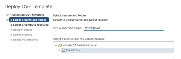
4. Select the destination compute resource and go to the next page.
5. Verify the template details and go to the next page.
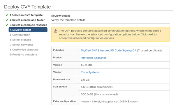
6. Select the appropriate deployment size.
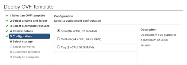
7. Select a destination and thin provision to optimize disk usage on the Select Storage page.
8. Select a source network and map it to the destination network.
9. On the customize template page, customize the deployment properties of the OVF template and provide an Admin Password and NTP and DNS server information. Click Next.
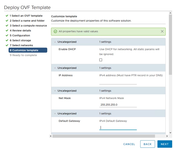
Set Up Cisco Intersight Assist
After installing Intersight Virtual Appliance, start the VM host in vCenter. After a short period of time connect to the host using your web browser to proceed with the configuration. Provide your proxy configuration in the settings section to connect the installer to the Internet.
To set up Cisco Intersight Assist, follow these steps:
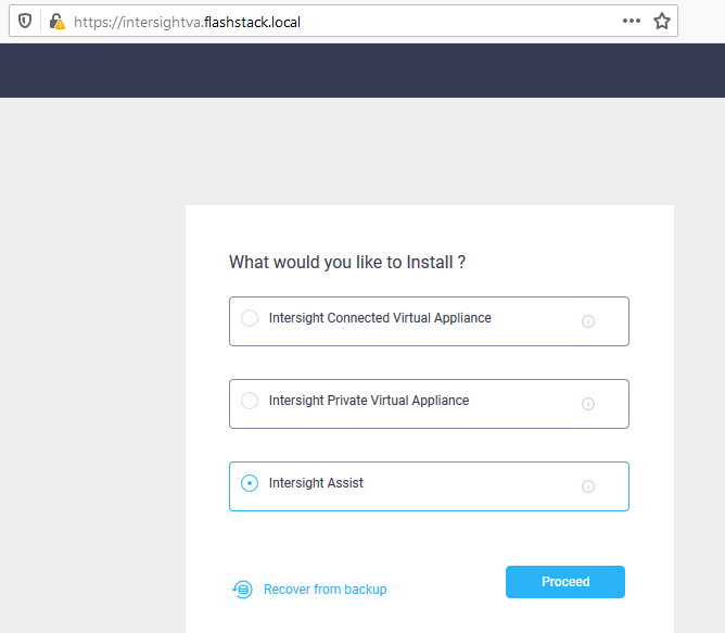
1. Select Intersight Assist and click Proceed to start the two-step approach installation.
2. Connect Intersight Virtual Appliance.
3. Software Download.
The first step provides the Device ID and Claim Code to claim the Virtual Appliance like a standard device in Cisco Intersight.
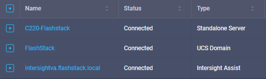
4. Once connected click Continue to move to the second setup step and wait for the download to complete which can take some time.
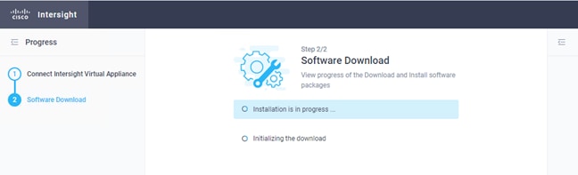
Claim the Fabric Interconnects
To connect and access Cisco Intersight, follow these steps:
1. In Cisco UCS Manager, click the Admin tab in the navigation pane.
2. Select Device Connector from the drop-down list.
3. Click Settings and provide the DNS, NTP and proxy configuration. Click Save.
4. Enable Intersight Management.
5. In Cisco Intersight, click the Admin > Devices tab in the navigation pane.
6. Click Claim a new device.
7. Copy & Paste the Device ID and Claim Code from Cisco USCM.

8. Click Claim to connect the fabric interconnects to Cisco Intersight.
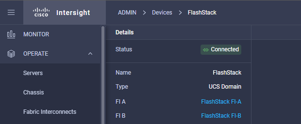
9. Click on one of the Fabric Interconnects to review chassis and server status. From the tool menu it is possible to open a TAC support case right away from Intersight uploading the tech support information for further troubleshooting as well.
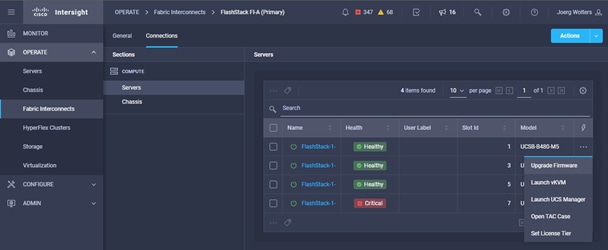
Claim the FlashArray//X
To claim the FlashArray as new device in Cisco Intersight, follow these steps:
1. Connect to Cisco Intersight.
2. In Cisco Intersight, click the Admin > Devices tab in the navigation pane.
3. Click Claim a new device.
4. Click the Claim Through Intersight Assist tab.
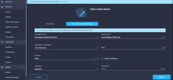
5. Select device type Pure Storage FlashArray.
6. Enter the hostname or IP address.
7. Enter pureuser as username and the user password. Click Claim.
8. Once the claim process completes the FlashArray//X is listed as new device.

9. Click Operation > Storage tab in the navigation pane.
![]()
10. Select the FlashArray//X and obtain capacity and usage information from the overview tab.
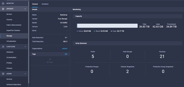
11. Monitor all host and volume information from the Inventory tab.
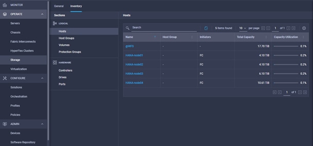
SAP HANA Hardware and Cloud Measurement
The SAP HANA hardware and cloud measurement tool (HCMT) collects information on the infrastructure intended for SAP HANA deployments. The tool measures the key performance indicator requirements defined by SAP and helps to understand the infrastructure can achieve satisfactory base performance as well as overall performance given the intended SAP HANA usage. The measurement results are saved into a single file, which can be uploaded to the SAP HANA hardware and cloud measurement analysis web page for further analysis and reporting.
SAP note 2493172 - SAP HANA Hardware and Cloud Measurement Tools provides more detailed information on the usage of the HCMT tool. It runs a series of automated tests, for example network tests, file system consistency tests or storage and CPU benchmark tests.
The HCMT execution plan for SAP HANA Scale Up environments doesn’t require any modification. To include the non-volatile DC PMM memory configuration, adapt the execution plan and provide the appropriate value for the parameter NvmBasePath:
# vi <path>/setup/config/executionplan.json
{
"Comment": "Persistent memory mount paths, keep this empty for non nvm systems",
"Name": "NvmBasePath",
"Value": [ "/hana/pmem/nvmem0,/hana/pmem/nvmem1,/hana/pmem/nvmem2,/hana/pmem/nvmem3" ],
"Request": "true"
},
The HCMT execution plan for SAP HANA Scale Out environments require some modifications as well. Add the Scale Out hosts for the Hosts parameter and insert two new sections with the HANA log and data volume information of the additional hosts:
# vi <path>/setup/config/executionplan.json
{
"Comment": "Hosts for scale-out measurements, keep this empty for scale-up",
"Name": "Hosts",
"Value": "cishana02,cishana03",
"Request": "true"
},
{
"Comment": "Hosts for scale-out measurements, keep this empty for scale-up",
"Name": "LogVolumeHosts",
"Value": [ "/hana/log", "/hana/log" ],
"Request": "true"
},
{
"Comment": "Hosts for scale-out measurements, keep this empty for scale-up",
"Name": "DataVolumeHosts",
"Value": [ "/hana/data", "/hana/data" ],
"Request": "true"
},
Because of the long HCMT runtime it is recommended to run the SSH terminal(s) within the jump host. Execute the tool on the command line:
# ./hcmt -v -p <path>/setup/config/executionplan.json
Upload the measurement result file to see whether the infrastructure setup meets the configuration and performance requirements.
1. Connect to https://hotui-supportportal.dispatcher.hana.ondemand.com/index.html
2. Authenticate with your S-User ID.
3. Create a new host entry and provide the requested server details.
4. Select the host entry and press the arrow menu entry to upload the measurement data.
5. Follow the onscreen instructions and click Submit.
The HCMT analysis provides a graphical and textual representation of your measurement results. It allows you to see which parts of your system are doing well and which parts may need some changes or improvements to achieve the required performance.
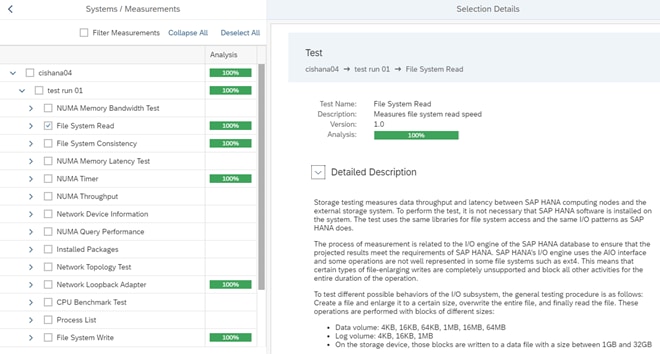
For Scale-Out environments HCMT will run on all nodes in parallel and the HCMT analysis provides the result of the network topology tests for the host to host communication in addition to the test runs of a Scale Up node.
SAP HANA Scale Out High Availability Test
SAP HANA Scale-Out deployments leverage the inherit HA capabilities of SAP HANA having a standby host running within the same SAP HANA topology.
The test plan included four different failover test scenarios:
● Deactivate a worker node by rebooting the node
● Failover and failback with tidy mountpoints from and to the master nameserver
● Trigger a double failover when the standby node is not a master as well.
● Cause a split-brain situation deactivating the management and internode network interfaces.
All scenarios provide either a continuous operation except of the split-brain situation in the 2+1 setup, when SAP HANA operation continued after ethernet network connectivity is reestablished.
The Cisco and Pure Storage converged infrastructure solution, FlashStack, delivers maximum performance and reliability for business-critical applications with all flash storage. The best-in-class storage, server and network components serve as a foundation for a variety of workloads not limited to SAP HANA. The architectural design can be quickly and confidently deployed. FlashStack Datacenter is predesigned to provide agility to the large enterprise data centers with high availability and storage scalability. With a FlashStack solution, customers can leverage a secure, integrated, and optimized stack that includes compute, network, and storage resources that are sized, configured, and deployed in a flexible manner.
Cisco Intersight provides management and support capabilities for the Intersight-connected environment including the Pure Storage FlashArray//X and all information pertaining to VMware vSphere vCenter. It simplifies the infrastructure management and provides proactive support for the FlashStack environment.
Some Intersight capabilities are:
● View general and inventory hardware information including the Pure Storage FlashArray//X.
● Manage and monitor the Cisco UCS server nodes and the Pure Storage FlashArray//X.
● View VMware vSphere vCenter general and inventory information - Datacenters, Clusters, Hosts, Virtual Machines and Datastores.
● Using the workflow designer, create and execute your own workflows manipulating storage and other infrastructure components together to automate initial deployment/ device reconfiguration or to deploy/configure VMware vSphere components.
FlashStack is a flexible infrastructure platform composed of pre-sized storage, networking, and server components. It is designed to ease your IT transformation and operational challenges with maximum efficiency and minimal risk.
FlashStack differs from other solutions and is so powerful for SAP environments by providing:
● Integrated, validated technologies from industry leaders and top-tier software partners.
● Cisco UCS stateless computing architecture provided by the Service Profile capability of Cisco UCS allows for fast, non-disruptive workload changes to be executed simply and seamlessly across the integrated Cisco UCS infrastructure and Cisco x86 servers.
● A single platform built from unified compute, fabric, and storage technologies, allowing you to scale to large-scale data centers without architectural changes.
● Centralized, simplified management of all infrastructure resources, including the FlashArray//X through Cisco Intersight.
● Evergreen storage so you will never pay for more storage than you need, but still have ample storage available on demand when you need it.
● A flexible Cooperative Support Model that resolves issues rapidly and spans across new and legacy products.
Appendix 1: Configuration Variables
This appendix summarized the configuration variables required to configure the FlashStack environment.
Table 15. Cisco Nexus Switch Configuration Variables
| Variable name |
Description |
Custom Value |
| <var_nexus_A_hostname> |
Cisco Nexus A host name |
|
| <var_nexus_A_mgmt0_ip> |
Out-of-band Cisco Nexus A management IP address |
|
| <var_oob_vlan_net> |
Out-of-band management network netmask |
|
| <var_oob_vlan_gw> |
Out-of-band management network default gateway |
|
| <var_nexus_B_hostname> |
Cisco Nexus B host name |
|
| <var_nexus_B_mgmt0_ip> |
Out-of-band Cisco Nexus B management IP address |
|
| <var_global_ntp_server_ip> |
NTP server IP address |
|
| <var_nexus_vpc_domain_id> |
Unique Cisco Nexus switch VPC domain ID for Nx93180YC-FX switch pair |
|
| <var_ucs_clustername> |
Cisco UCS Manager cluster host name |
|
Table 16. VLAN ID Configuration Variables
| Variable name |
Description |
Custom Value |
| <var_oob_vlan_id> |
Out-of-band management interfaces |
76 |
| <var_client_vlan_id> |
Client Network for HANA Data/log VLAN ID |
222 |
| <var_appserver_vlan_id> |
Application Server Network for HANA Data/log VLAN ID |
223 |
| <var_datasource_vlan_id> |
Data source Network for HANA Data/log VLAN ID |
224 |
| <var_backup_vlan_id> |
Backup Network for HANA Data/log VLAN ID |
221 |
| <var_nfs-shared_vlan_id> |
/hana/shared NFS network |
111 |
| <var_internal_vlan_id> |
Node to Node Network for HANA Data/log VLAN ID |
220 |
| <var_replication_vlan_id> |
Replication Network for HANA Data/log VLAN ID |
225 |
Table 17. Cisco MDS Switch Configuration Variables
| Variable name |
Description |
Custom Value |
| <var_mds-A_hostname> |
Cisco MDS A host name |
|
| <var_mds-A_ mgmt0_ip> |
Out-of-band Cisco MDS A management IP address |
|
| <var_mds-B_hostname> |
Cisco MDS B host name |
|
| <var_mds-B_ mgmt0_ip> |
Out-of-band Cisco MDS B management IP address |
|
| <var_oob_vlan_net> |
Out-of-band management network netmask |
|
| <var_oob_vlan_gw> |
Out-of-band management network default gateway |
|
| <var_global_ntp_server_ip> |
NTP server IP address |
|
| <var_fc-pc_A_id> |
Fibre Channel - Port Channel ID for MDS A |
|
| <var_fc-pc_B_id> |
Fibre Channel - Port Channel ID for MDS B |
|
| <var_san_A_id> |
VSAN ID for MDS A |
|
| <var_san_B_id> |
VSAN ID for MDS B |
|
Table 18. Cisco Fabric Interconnect Configuration Variables
| Variable name |
Description |
Custom Value |
| <var_passwd> |
Cisco UCS Admin Password |
|
| <var_ucs_clustername> |
Cisco UCS Manager cluster host name |
|
| <var_ucsa_mgmt_ip> |
Cisco UCS fabric interconnect (FI) A out-of-band management IP address |
|
| <var_ucsb_mgmt_ip> |
Cisco UCS fabric interconnect (FI) B out-of-band management IP address |
|
| <var_oob_vlan_net> |
Out-of-band management network netmask |
|
| <var_oob_vlan_gw> |
Out-of-band management network default gateway |
|
| <var_ucs_cluster_ip> |
Cisco UCS Manager cluster IP address |
|
| <var_ucsb_mgmt_ip> |
Cisco UCS FI B out-of-band management IP address |
|
| <var_nameserver_ip> |
DNS Server IP address |
|
| <var_dns_domain_name> |
Default Domain Name |
|
Table 19. Cisco UCS Configuration Variables
| Variable name |
Description |
Custom Value |
| <var_ipmi_username> |
IPMI/Redfish username |
sapadm |
| <var_ipmi_password> |
IPMI/Redfish user password |
|
Table 20. Server01 Configuration Variables
| Variable name |
Description |
Custom Value |
| <var_server01_mgmt_ip> |
Management Host IP address |
|
| <var_server01_mgmt_hostname> |
Management Host name |
|
| <var_server01_hostname> |
Server Host Name |
|
| <var_os_default_IPv4_gateway> |
Default IPv4 Gateway |
|
| <var_client_ipaddr-node1> |
Client Network IP address |
|
| <var_appserver_ipaddr-node1> |
Application Server Network IP address |
|
| <var_datasource_ipaddr-node1> |
Data source Network IP address |
|
| <var_backup_ipaddr-node1> |
Backup Network IP address |
|
| <var_nfs-shared_ipaddr-node1> |
HANA shared NFS network IP address |
|
| <var_internal_ipaddr-node1> |
Internode Network IP address |
|
| <var_replication_ipaddr-node1> |
Replication Network IP address |
|
| <var_os_root_pw> |
Root password |
|
Table 21. Pure Storage Configuration Variables Windows Failover Cluster IPs
| Ethernet IP Address Requirement |
Default DNS Hostname |
Validation setup values |
| <var_oob_purect0_ip> |
FlashArray//X CT0 controller out-of-band management IP |
|
| <var_oob_purect1_ip> |
FlashArray//X CT1 controller out-of-band management IP |
|
| <var_oob_pure_gw> |
FlashArray//X out-of-band management network default gateway |
|
| < var_oob_purec_net> |
FlashArray//X out-of-band management network netmask |
|
| <var_purecluster_net> |
Purity//FA Cluster IP netmask |
|
Appendix 2: Reference
SAP HANA TDI Documentation
SAP HANA TDI: Overview
http://go.sap.com/documents/2016/05/827c26ba-717c-0010-82c7-eda71af511fa.html
SAP HANA TDI: FAQ
http://go.sap.com/documents/2016/05/e8705aae-717c-0010-82c7-eda71af511fa.html
SAP HANA TDI: Storage Requirements
http://go.sap.com/documents/2015/03/74cdb554-5a7c-0010-82c7-eda71af511fa.html
SAP HANA TDI: Network Requirements
https://www.sap.com/documents/2016/08/1cd2c2fb-807c-0010-82c7-eda71af511fa.html
SAP Notes
● SAP Note 2235581 - SAP HANA: Supported Operating Systems
● SAP Note 2578899 - SUSE Linux Enterprise Server 15: Installation Note
● SAP Note 2684254 - SAP HANA DB: Recommended OS settings for SLES 15 for SAP Applications 15
● SAP Note 1275776 - Linux: Preparing SLES for SAP environments
● SAP Note 2526952 - Red Hat Enterprise Linux for SAP Solutions
● SAP Note 2772999 - Red Hat Enterprise Linux 8.x: Installation and Configuration
● SAP Note 2777782 - SAP HANA DB: Recommended OS Settings for RHEL 8
● SAP Note 2382421 - Optimizing the Network Configuration on HANA- and OS-Level
● SAP Note 2493172 - SAP HANA Hardware and Cloud Measurement Tools
Cisco
FlashStack for SAP HANA TDI Design Guide
Performance Tuning Guide for Cisco UCS M5 Servers
Cisco UCS for SAP HANA with Intel Optane DC Persistent Memory Module
Cisco MDS 9000 Family NX-OS Fabric Configuration Guide - Configuring and Managing Zones
Cisco Intersight Help Center
https://intersight.com/help/home
Overview Cisco Intersight Assist
Configure a Cisco AppDynamics Monitoring Solution for SAP Applications: https://www.cisco.com/c/en/us/solutions/collateral/data-center-virtualization/unified-computing/appd-sap-monitoring-wp.html
Pure Storage
SAP HANA Implementation Best Practices on FlashArray//X
SAP Applications on Pure Storage FlashStack
https://www.purestorage.com/solutions/applications/sap.html
FlashArray//X Series
https://www.purestorage.com/products/nvme/flasharray-x.html
Intel
Persistent Memory Wiki
https://nvdimm.wiki.kernel.org/2mib_fs_dax
Linux
EDAC project
http://bluesmoke.sourceforge.net
MCE log
http://bluesmoke.sourceforge.net
Joerg Wolters, Technical Marketing Engineer, Cisco Systems GmbH
Joerg is a Technical Marketing Engineer and part of the Cisco Cloud and UCS Solutions Group. Joerg has over seven years of experience with SAP HANA on Cisco UCS platform. Previously Joerg led the Cisco Solution Support for SAP HANA and his current focus is on the Converged Infrastructure Solution design, validation and associated marketing collaterals’ build for SAP applications and SAP HANA.
Acknowledgements
For their support and contribution to the design, validation, and creation of this Cisco Validated Design and Deployment Guide, the author would like to thank:
● Shailendra Mruthunjaya, Technical Marketing Engineer, Cisco Systems, Inc.
● Pramod Ramamurthy, Technical Marketing Engineer, Cisco System GmbH
● Andrew Sillifant, Solution Architect, Pure Storage UK Ltd.
For comments and suggestions about this guide and related guides, join the discussion on Cisco Community at https://cs.co/en-cvds.