OpenShift 4 on FlashStack User Provisioned Infrastructure
Available Languages
Bias-Free Language
The documentation set for this product strives to use bias-free language. For the purposes of this documentation set, bias-free is defined as language that does not imply discrimination based on age, disability, gender, racial identity, ethnic identity, sexual orientation, socioeconomic status, and intersectionality. Exceptions may be present in the documentation due to language that is hardcoded in the user interfaces of the product software, language used based on RFP documentation, or language that is used by a referenced third-party product. Learn more about how Cisco is using Inclusive Language.
- US/Canada 800-553-2447
- Worldwide Support Phone Numbers
- All Tools
 Feedback
 Feedback

OpenShift 4 on FlashStack User Provisioned Infrastructure
Deployment Guide for OpenShift on FlashStack with Cisco UCS 6400 Fabric Interconnect and Pure Storage
FlashArray//X70 R2
Published: August 2020

In partnership with: ![]()
About the Cisco Validated Design Program
The Cisco Validated Design (CVD) program consists of systems and solutions designed, tested, and documented to facilitate faster, more reliable, and more predictable customer deployments. For more information, go to:
http://www.cisco.com/go/designzone.
ALL DESIGNS, SPECIFICATIONS, STATEMENTS, INFORMATION, AND RECOMMENDATIONS (COLLECTIVELY, "DESIGNS") IN THIS MANUAL ARE PRESENTED "AS IS," WITH ALL FAULTS. CISCO AND ITS SUPPLIERS DISCLAIM ALL WARRANTIES, INCLUDING, WITHOUT LIMITATION, THE WARRANTY OF MERCHANTABILITY, FITNESS FOR A PARTICULAR PURPOSE AND NONINFRINGEMENT OR ARISING FROM A COURSE OF DEALING, USAGE, OR TRADE PRACTICE. IN NO EVENT SHALL CISCO OR ITS SUPPLIERS BE LIABLE FOR ANY INDIRECT, SPECIAL, CONSEQUENTIAL, OR INCIDENTAL DAMAGES, INCLUDING, WITHOUT LIMITATION, LOST PROFITS OR LOSS OR DAMAGE TO DATA ARISING OUT OF THE USE OR INABILITY TO USE THE DESIGNS, EVEN IF CISCO OR ITS SUPPLIERS HAVE BEEN ADVISED OF THE POSSIBILITY OF SUCH DAMAGES.
THE DESIGNS ARE SUBJECT TO CHANGE WITHOUT NOTICE. USERS ARE SOLELY RESPONSIBLE FOR THEIR APPLICATION OF THE DESIGNS. THE DESIGNS DO NOT CONSTITUTE THE TECHNICAL OR OTHER PROFESSIONAL ADVICE OF CISCO, ITS SUPPLIERS OR PARTNERS. USERS SHOULD CONSULT THEIR OWN TECHNICAL ADVISORS BEFORE IMPLEMENTING THE DESIGNS. RESULTS MAY VARY DEPENDING ON FACTORS NOT TESTED BY CISCO.
CCDE, CCENT, Cisco Eos, Cisco Lumin, Cisco Nexus, Cisco StadiumVision, Cisco TelePresence, Cisco WebEx, the Cisco logo, DCE, and Welcome to the Human Network are trademarks; Changing the Way We Work, Live, Play, and Learn and Cisco Store are service marks; and Access Registrar, Aironet, AsyncOS, Bringing the Meeting To You, Catalyst, CCDA, CCDP, CCIE, CCIP, CCNA, CCNP, CCSP, CCVP, Cisco, the Cisco Certified Internetwork Expert logo, Cisco IOS, Cisco Press, Cisco Systems, Cisco Systems Capital, the Cisco Systems logo, Cisco Unified Computing System (Cisco UCS), Cisco UCS B-Series Blade Servers, Cisco UCS C-Series Rack Servers, Cisco UCS S-Series Storage Servers, Cisco UCS Manager, Cisco UCS Management Software, Cisco Unified Fabric, Cisco Application Centric Infrastructure, Cisco Nexus 9000 Series, Cisco Nexus 7000 Series. Cisco Prime Data Center Network Manager, Cisco NX-OS Software, Cisco MDS Series, Cisco Unity, Collaboration Without Limitation, EtherFast, EtherSwitch, Event Center, Fast Step, Follow Me Browsing, FormShare, GigaDrive, HomeLink, Internet Quotient, IOS, iPhone, iQuick Study, LightStream, Linksys, MediaTone, MeetingPlace, MeetingPlace Chime Sound, MGX, Networkers, Networking Academy, Network Registrar, PCNow, PIX, PowerPanels, ProConnect, ScriptShare, SenderBase, SMARTnet, Spectrum Expert, StackWise, The Fastest Way to Increase Your Internet Quotient, TransPath, WebEx, and the WebEx logo are registered trademarks of Cisco Systems, Inc. and/or its affiliates in the United States and certain other countries.
All other trademarks mentioned in this document or website are the property of their respective owners. The use of the word partner does not imply a partnership relationship between Cisco and any other company. (0809R)
© 2020 Cisco Systems, Inc. All rights reserved.
Table of Contents
Deployment Hardware and Software
Create OpenShift User Provisioned Infrastructure
Prepare OpenShift User Provisioned Infrastructure Deployment
Create and Prepare Installation Files
Install and Create the Ignition Configuration Files on Mgmt-host
Configure External Dependencies
Deploy and Configure OpenShift Container Platform Cluster
Cisco Validated Designs (CVDs) consist of systems and solutions that are designed, tested, and documented to facilitate and improve customer deployments. These designs incorporate a wide range of technologies and products into a portfolio of solutions that have been developed to address the business needs of our customers.
This document details the design described in the Design Guide for OpenShift 4.3 on FlashStack User Provisioned Infrastructure, which showed a validated converged infrastructure jointly developed by Cisco and Pure Storage. In this solution we will walk through the deployment of a predesigned, best-practice data center architecture with OpenShift 4.3 deployed on VMware vSphere built on the Cisco Unified Computing System (Cisco UCS), the Cisco Nexus® 9000 family of switches, and Pure Storage FlashArray//X R2 all flash storage configured for iSCSI based storage access.
When deployed, the architecture presents a robust infrastructure viable for a wide range of application workloads implemented as containers.
Solution Overview
Introduction
In the current industry there is a trend for pre-engineered solutions which standardize the data center infrastructure, offering the business operational efficiencies, agility, and scale to address cloud, bi-modal IT, and their business. Their challenge is complexity, diverse application support, efficiency, and risk; all these are met by FlashStack with:
· Reduced complexity and automatable infrastructure and easily deployed resources
· Robust components capable of supporting high performance and high bandwidth virtualized applications
· Efficiency through optimization of network bandwidth and in-line storage compression with de-duplication
· Risk reduction at each level of the design with resiliency built into each touch point throughout
Cisco and Pure Storage have partnered to deliver this Cisco Validated Design, combining storage, server, and network components to serve as the foundation for virtualized workloads, enabling efficient architectural designs that can be quickly and confidently deployed.
Audience
The intended audience for this document includes, but is not limited to, DevOps managers, IT infrastructure managers, application development leaders, business digital transformation leaders, storage and data management managers, sales engineer and architects working with hybrid and private clouds, and other parties that are looking for a tested, market-proven CI solution that offers flexibility and simplicity in support of their cloud native and application modernization needs along with their digital transformation journey.
Purpose of this Document
This document details a step-by-step configuration and implementation guide for deploying OpenShift on the FlashStack solution. This will cover the provisioning on the deployment, bootstrap, master, and work nodes. This will also cover the configuration of DCHP, DNS, and Load Balancer entries required to support this solution but will not cover the overall deployment of these external resources. The details for deploying the underlying FlashStack solution, including configuration for the Cisco UCS, Cisco Nexus, Pure Storage FlashArray//X70 R2, and VMware vSphere can be found in FlashStack Virtual Server Infrastructure with iSCSI Storage for VMware vSphere 6.7 available here: https://www.cisco.com/c/en/us/td/docs/unified_computing/ucs/UCS_CVDs/flashstack_vsi_iscsi_vm67_u1.html
Solution Summary
The FlashStack Virtual Server Infrastructure is a validated reference architecture, collaborated on by Cisco and Pure Storage, built to serve enterprise data centers. The solution is built to deliver a VMware vSphere based environment, leveraging the Cisco Unified Computing System (Cisco UCS), Cisco Nexus switches, and Pure Storage FlashArray.
The architecture brings together a simple, wire once solution that is SAN booted from iSCSI and is highly resilient at each layer of the design. This creates an infrastructure that is ideal for a variety of virtualized and containerized application deployments that can reliably scale when growth is needed.
Figure 1 shows the base physical architecture used in FlashStack Virtual Server Infrastructure.
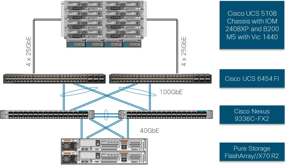
The reference hardware configuration includes:
· Two Cisco Nexus 9336C-FX2 Switches
· Two Cisco UCS 6454 Fabric Interconnects
· Cisco UCS 5108 Chassis with two Cisco UCS 2408 Fabric Extenders
· Three Cisco UCS B200 M5 Blade Servers
· One Pure Storage FlashArray//X70 R2
The virtual environment this supports is within VMware vSphere 6.7 U3 and includes virtual management and automation components from Cisco and Pure Storage built into the solution, or as optional add-ons.
This document assumes that this environment is deployed based on the FlashStack Virtual Server Infrastructure with iSCSI Storage deployment guide.
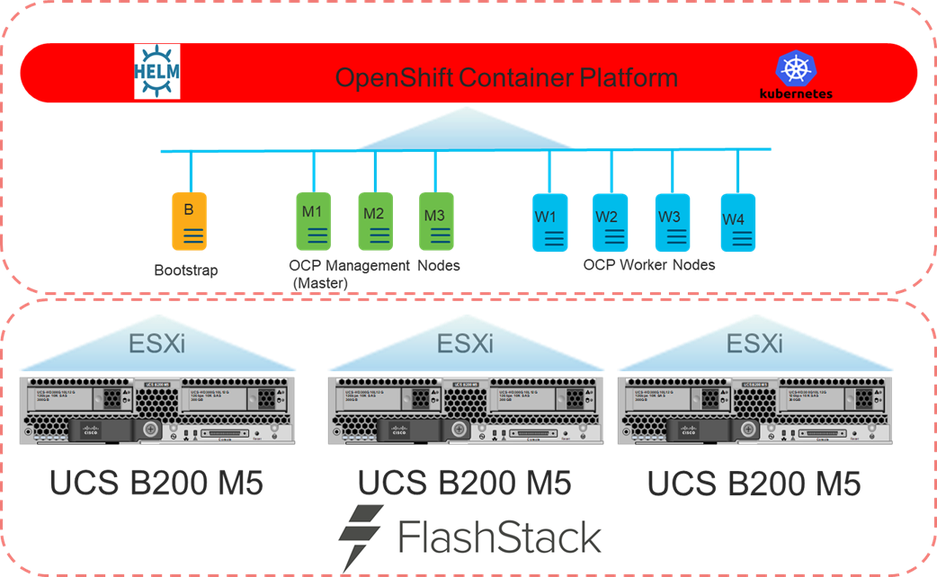
Figure 2 shows the base logical computing architecture used to deploy the OpenShift Container Platform (OCP) on the User Provisioned FlashStack VSI. It shows the Bootstrap, Management, and Work nodes deployed as virtual machines on the physical environment displayed in Figure 1.
Software Revisions
Table 1 lists the software versions for hardware and virtual components used in this solution. Each of these versions have been used have been certified within interoperability matrixes supported by Cisco, Pure Storage, and VMware. For more current supported version information, consult the following sources:
· FlashStack Compatibility Matrix: https://support.purestorage.com/FlashStack/Product_Information/FlashStack_Compatibility_Matrix
· Cisco UCS Hardware and Software Interoperability Tool: http://www.cisco.com/web/techdoc/ucs/interoperability/matrix/matrix.html
· Pure Storage Interoperability(note, this interoperability list will require a support login form Pure): https://support.purestorage.com/FlashArray/Getting_Started/Compatibility_Matrix
· VMware Compatibility Guide: http://www.vmware.com/resources/compatibility/search.php
Additionally, it is also strongly suggested to align FlashStack deployments with the recommended release for the Cisco Nexus 9000 switches used in the architecture:
![]() If versions are selected that differ from the validated versions below, it is highly recommended to read the release notes of the selected version to be aware of any changes to features or commands that may have occurred.
If versions are selected that differ from the validated versions below, it is highly recommended to read the release notes of the selected version to be aware of any changes to features or commands that may have occurred.
| Layer |
Device |
Version |
Comments |
| Compute |
Cisco UCS Fabric Interconnects 6400 Series, UCS B-200 M5, UCS C-220 M5 |
4.1(1c) |
Includes Cisco UCS IOM 2408 and Cisco VIC 1400 Series |
| Network |
Cisco Nexus 9000 NX-OS |
7.0(3)I7(5) |
|
| Storage |
Pure Storage FlashArray//X70 R2 |
5.3.2 |
|
| Software |
Cisco UCS Manager |
4.1(1c) |
|
|
|
VMware vSphere ESXi Cisco Custom ISO |
6.7 U3 |
|
|
|
VMware vSphere nenic Driver for ESXi |
1.0.31.0-1OEM |
|
|
|
VMware vCenter |
6.7 U3 |
|
|
|
OCP Master Node |
RHCOS 4.3 |
|
|
|
OCP Worker Node |
RCHOS 4.3 |
|
|
|
OCP Bootstrap Node |
RCHOS 4.3 |
|
|
|
Deployment node |
RHEL 7.6 |
|
|
|
Pure Service Orchestrator |
5.2 |
|
|
|
RedHat OpenShift Container Platform |
4.3 |
|
Configuration Guidelines
This document details the step-by-step configuration of a fully redundant and highly available Kubernetes Container Infrastructure built on Cisco, Pure Storage, and RedHat components. References are made to which component is being configured with each step, either 01, 02, and so on. For example, Master-01 and Master-02 are used to identify the two of the OCP Master Nodes within the cluster that is provisioned with this document, and Cisco Nexus A or Cisco Nexus B identifies the pair of Cisco Nexus switches that are configured. Additionally, this document details the steps for provisioning multiple Cisco UCS hosts, and these examples are identified as: OCP-VM-Host-iSCSI-01, OCP-VM-Host-iSCSI-02, etc to represent iSCSI booted infrastructure and production hosts deployed to the fabric interconnects in this document. Finally, to indicate that you should include information pertinent to your environment in a given step, <<text>> appears as part of the command structure. See the following example during a configuration step for both Cisco Nexus switches:
AA12-9336C-A&B (config)# ntp server <<var_oob_ntp>> use-vrf management
This document is intended to enable you to fully configure the customer environment. In this process, various steps require you to insert customer-specific naming conventions, IP addresses, and VLAN schemes, as well as to record appropriate MAC addresses. Table 2 lists the VLANs necessary for deployment as outlined in this guide, and Table 3 lists the virtual machines (VMs) necessary for deployment as outlined in this guide.
| VLAN Name |
VLAN Purpose |
ID used in Validating this Document |
Customer Deployed Value |
| Native |
VLAN for untagged frames |
2 |
|
| Out of Band Mgmt |
VLAN for out-of-band management interfaces |
15 |
|
| In-band Mgmt |
VLAN for in-band management interfaces |
215 |
|
| vMotion |
VLAN for vMotion |
1130 |
|
| OCP-Mgmt |
VLAN for the management/network interface for the OCP Bootstrap, Master, and Worker Nodes |
215 |
|
| iSCSI-A |
VLAN for iSCSI A |
1110 |
|
| iSCSI-B |
VLAN for iSCSI b |
1120 |
|
Table 3 Infrastructure Servers and FlashStack Components
| Variable Name |
Variable Description |
FQDN Name/IP used in Validating this Document |
Customer Deployed Value |
| <<var_dhcp_server>> |
DHCP Server |
10.2.164.122 |
<<var_dhcp_server>> |
| <<var_dns_server>> |
DNS Server |
10.2.164.122 |
<<var_dns_server>> |
| <<var_web_server>> |
Web Server |
repo.flashstack.cisco.com |
<<var_web_server>> |
| <<var_load_1_server>> |
Load Balance 2 |
proxy-01.flashstack.cisco.com |
<<var_load_1_server>> |
| <<var_load_2_server>> |
Load Balancer 2 |
proxy-02.flashstack.cisco.com |
<<var_load_2_server>> |
| <<var_ntp_server>> |
NTP Server |
time.flashstack.cisco.com |
<<var_ntp_server>> |
| <<var_vcenter_server>> |
vCenter Server |
vcsa.flashstack.cisco.com |
<<var_vcenter_server>> |
| <<var_vcenter_user>> |
vCenter administrator |
administrator@fsv.local |
<<var_vcenter_user>> |
| <<var_vcenter_dc_name>> |
vCenter Datacenter |
OpenShift_4.3 |
<<var_vcenter_dc_name>> |
| <<var_shared_ds_name>> |
Shared datastore for OpenShift VMs |
OCP-Shared |
<<var_shared_ds_name>> |
| <<var_flasharray_ip>> |
FlashArray//X70 R2 |
AA12-FlashArray.flashstack.cisco.com/ 10.2.164.45 |
<<var_flasharray_ip>> |
| <<var_ucs_mgmt_name>> |
UCS Manager |
AA12-UCS.flashstack.cisco.com |
<<var_ucs_mgmt_name>> |
Table 4 OpenShift Variables
| Variable Name |
Variable Description |
FQDN Name/IP used in Validating this Document |
Customer Deployed Value |
| <<var_base_domain>> |
Base Domain for Cluster |
Cluster01 |
|
| <<var_cluster_dns_name>> |
DNS Server |
10.2.164.122 |
|
| <<var_installation_directory>> |
Directory used for OCP Installation program |
OCPFSV |
|
Prepare OpenShift User Provisioned Infrastructure Deployment
To prepare the Cisco UCS, Cisco Nexus, Pure Storage FlashArray//X R2, and VMware vSphere environment as a User Provisioned Infrastructure for this deployment, follow the FlashStack for vSphere 6.7 deployment guide located here: https://www.cisco.com/c/en/us/td/docs/unified_computing/ucs/UCS_CVDs/flashstack_vsi_iscsi_vm67_u1.html
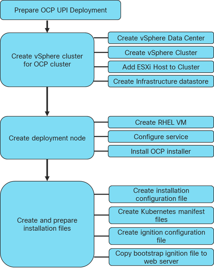
Create vSphere Cluster
Create vSphere Data Center
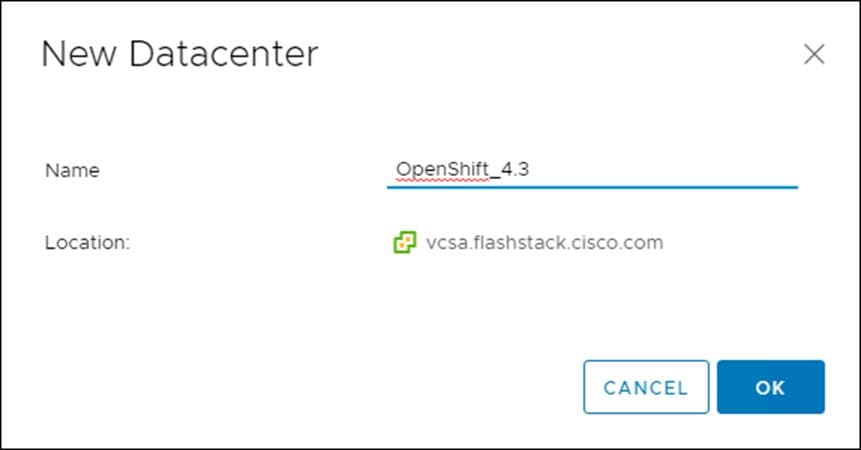
To create a vSphere data center, follow these steps:
1. Log into the vCenter Web Console.
2. Select Host and Clusters.
3. Right-click the vCenter icon and select New Datacenter… from the drop-down list.
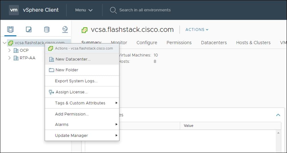
4. From the New Datacenter pop-up dialogue enter in a Datacenter name and click OK.
Create vSphere Cluster
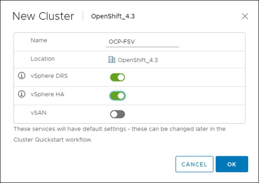
To create a vSphere cluster, follow these steps:
1. Right-click the Datacenter icon and select New Cluster… from the drop-down list.
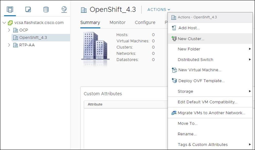
2. From the New Cluster pop-up dialogue enter in a Cluster name, enabled DRS and HA, and click OK.
Add ESXi Host
To add an ESXi host, follow these steps:
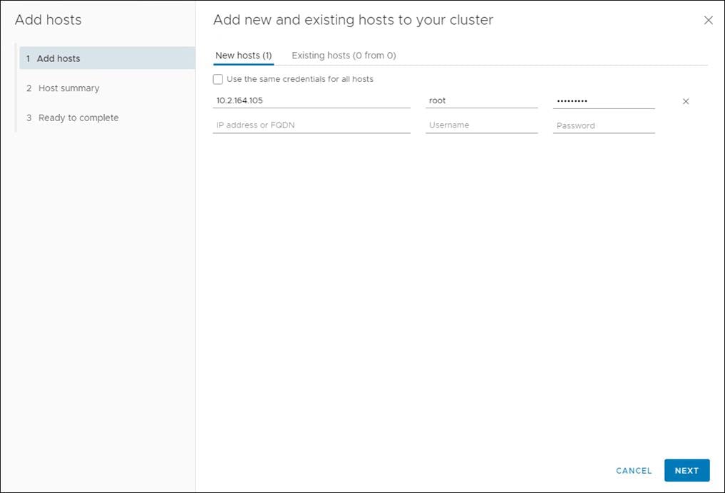
1. From the Cluster context select Configuration > Quick Start and click Add Host.
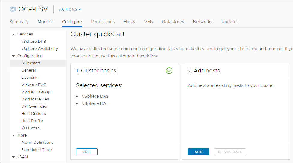
2. Enter the host IP/FQDN, username, and password. Click Next. Multiple host can be added at once.
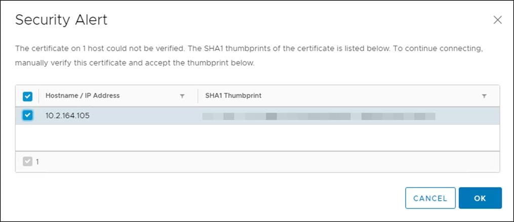
3. Verify the SHA1 Thumbprint and click OK.
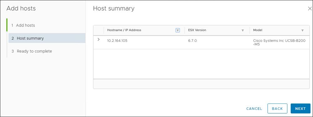
4. Confirm host Summary and click Next.
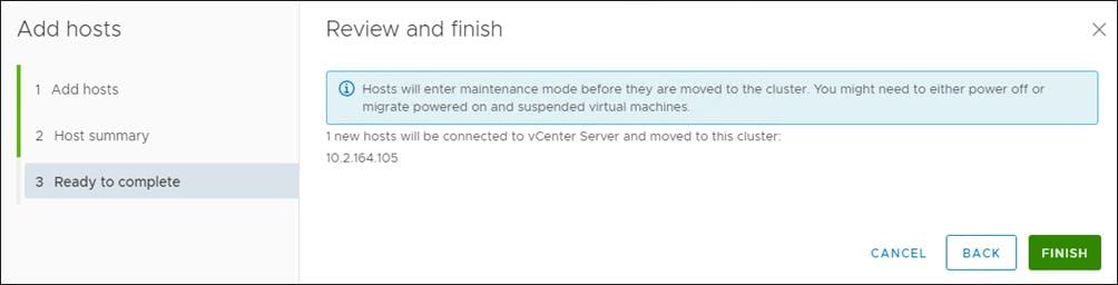
5. Click Finish.
The vSwitch, virtual distributed switch, iSCSI, and other host configurations are identical to those found in the FlashStack Virtual Server Infrastructure with iSCSI Storage for VMware vSphere 6.7 U1.
![]() For the OCP installation, use VFMS 6 datastores only.
For the OCP installation, use VFMS 6 datastores only.
Create Infrastructure Datastore (vCenter Plug-in)
A shared datastore will need to be created to be used by the BootStrap, Master, and Worker Virtual Machines. This will need to be configured to be used by the ESXi host used for this cluster.
1. In the vCenter Web Client click Host and Clusters.
2. Right-click the OCP Cluster and click Pure Storage.
3. Right-click the OCP Cluster and click Pure Storage -> Create Datastore.
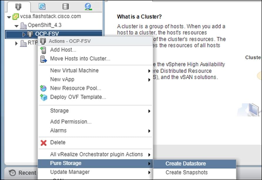
4. Set type to VMFS 6, Datastore name to <<var_shared_ds_name>>, and Cluster to the OCP Cluster.
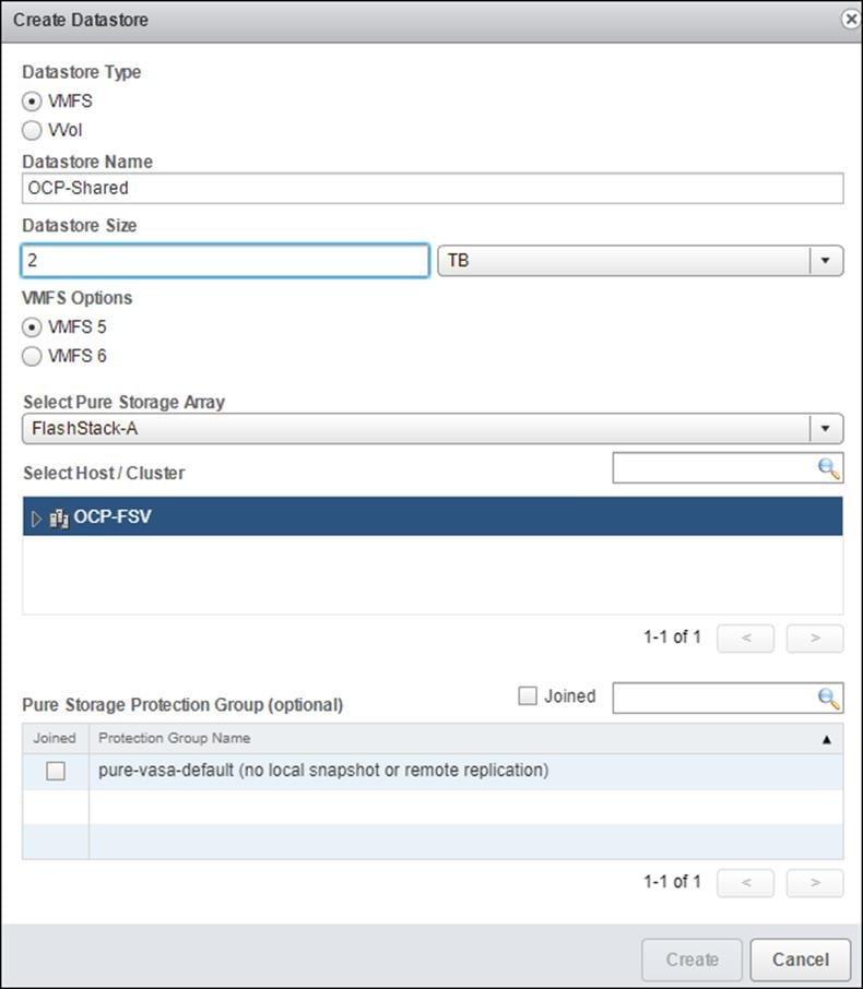
5. Select Create.
Create Deployment Node
Before deploying OpenShift Container Platform, you need to download the installation files to a locate computer. This must be Linux or macOS and requires 500 MB of free disk space.
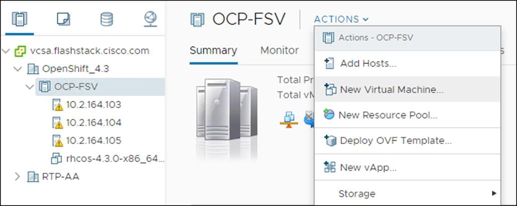
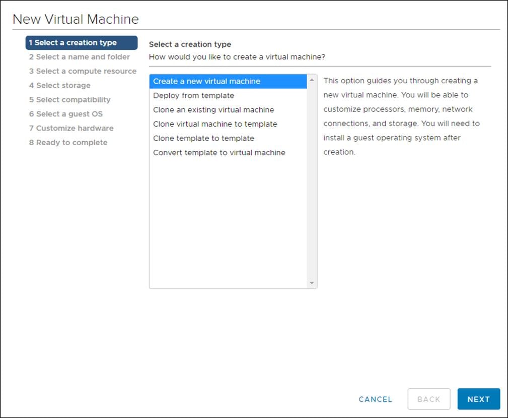
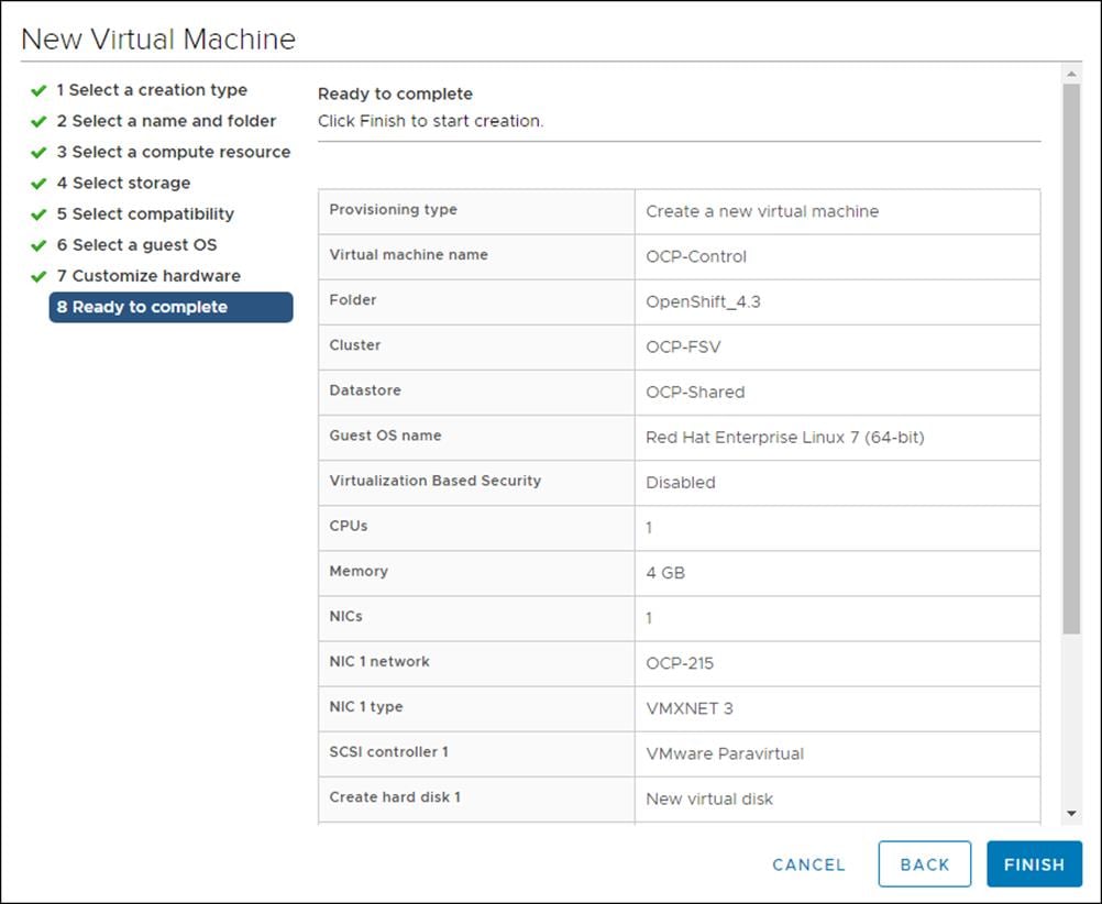
Create RHEL VM (optional)
To create a RHEL virtual machine, follow these steps:
1. Click Actions > New Virtual Machine…
2. Click Create a new virtual machine and click Next.
3. Click the compute cluster you wish to deploy this VM.
4. Click the Datastore you wish to use.
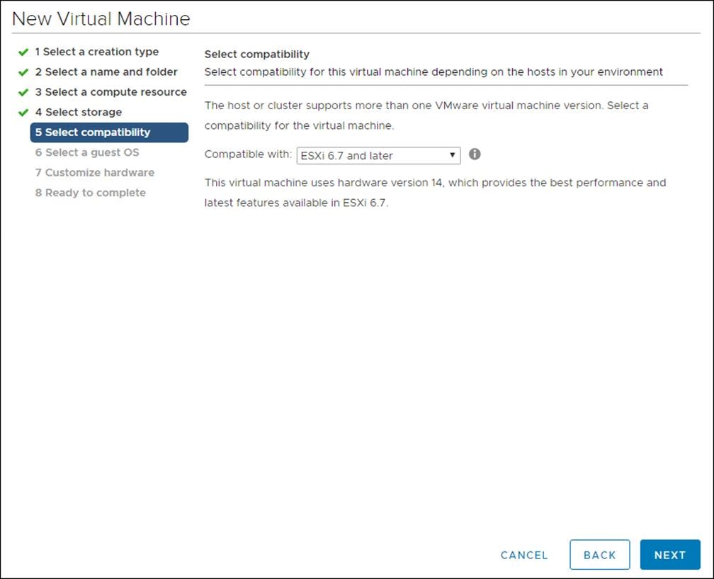
5. Set Compatibility to ESXi 6.7.
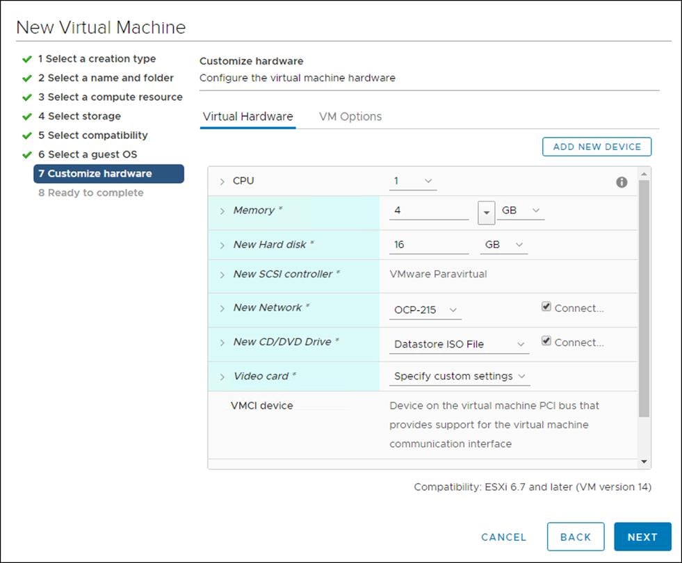
6. Click the hardware for this VM.
7. Review the settings and click Finish.
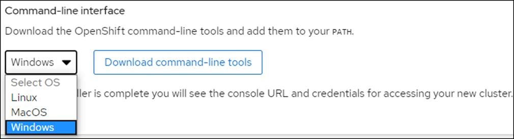
Install OCP Installation Program
To install OCP installation program, follow these steps:
1. Open a web browser to the OpenShift download portal: cloud.redhat.com/openshift/install
2. Click Run on VMware vSphere.
3. Select the appropriate OS for your installation computer and click Download.
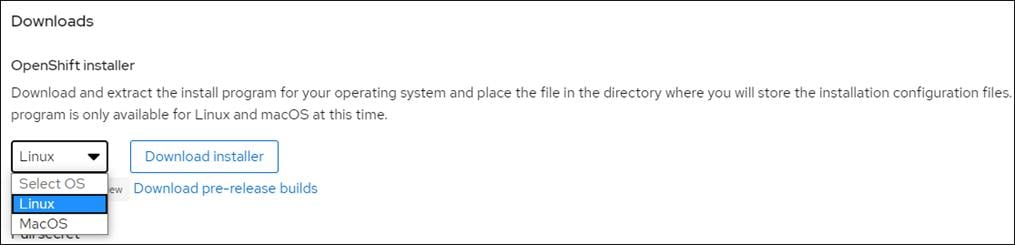
4. Copy your pull secret for later.

5. Download RHCOS if you do not have it.

6. Download the OpenShift command-line tool.
Create and Prepare Installation Files
For installations of OpenShift Container Platform that use user-provisioned infrastructure, we must manually generate the installation configuration file after the OCP installation program and the access token for the cluster are obtained.
To create installation configuration file, follow these steps:
1. Create an installation directory on the management host to store your required installation assets in:
$ mkdir <installation_directory>
Example: $ mkdir OCPFSV
![]() You must create a directory. Some installation assets, like bootstrap X.509 certificates have short expiration intervals, so you must not reuse an installation directory. If you want to reuse individual files from another cluster installation, you can copy them into your directory. However, the file names for the installation assets might change between releases. Use caution when copying installation files from an earlier OpenShift Container Platform version.
You must create a directory. Some installation assets, like bootstrap X.509 certificates have short expiration intervals, so you must not reuse an installation directory. If you want to reuse individual files from another cluster installation, you can copy them into your directory. However, the file names for the installation assets might change between releases. Use caution when copying installation files from an earlier OpenShift Container Platform version.
2. Customize the install-config.yaml file template and save it in the <installation_directory>.
3. Manually create a file and name this configuration file install-config.yaml.
$ touch install-config.yaml
4. For the install-config.yaml, if required, enter the following input:
· base domain
· OCP cluster id
· OCP pull secret
· ssh public key (~/.ssh/id_rsa.pub)
· vCenter host
· vCenter user
· vCenter password
· vCenter datacenter
· vCenter datastore
Sample install-config.yaml File for VMware vSphere
Customize the install-config.yaml file to specify more details about your OpenShift Container Platform cluster’s platform or modify the values of the required parameters shown in in red font below to suit your environment.
Example File
apiVersion: v1
baseDomain: <<var_base_domain>>
compute:
- hyperthreading: Enabled
name: worker
replicas: 0
controlPlane:
hyperthreading: Enabled
name: master
replicas: 3
metadata:
name: <<var_cluster_dns_name>>
platform:
vsphere:
vcenter: <<var_vcenter_server>>
username: <<var_vcenter_user>>
password: <<var_vcenter_password>>
datacenter: <<var_vcenter_dc_name>>
defaultDatastore: <<var_shared_ds_name>>
fips: false
pullSecret: '{"auths": ...}'
sshKey: 'ssh-ed25519 AAAA...'
File Used for the deployment:
apiVersion: v1
baseDomain: flashstack.cisco.com
compute:
- hyperthreading: Enabled
name: worker
replicas: 0
controlPlane:
hyperthreading: Enabled
name: master
replicas: 3
metadata:
name: cluster01
platform:
vsphere:
vcenter: vcsa.flashstack.cisco.com
username: administrator@fsv.local
password: PASSWORD
datacenter: OpenShift_4.3
defaultDatastore: OCP-Shared
fips: false
pullSecret: '{"auths": ...}'
sshKey: 'ssh-ed25519 AAAA...'
The required parameters displayed in red in the above file are described below simultaneously in the same order as they are listed in the file.
· baseDomain: The base domain of the cluster. All DNS records must be sub-domains of this base and include the cluster name.
· hyperthreading: Whether to enable or disable simultaneous multithreading, or hyperthreading. By default, simultaneous multithreading is enabled to increase the performance of your machines' cores.
· replicas: You must set the value of the replica’s parameter to 0. This parameter controls the number of workers that the cluster creates and manages for you, which are functions that the cluster does not perform when you use user-provisioned infrastructure. We will manually deploy worker machines for the cluster to use before you finish installing OpenShift Container Platform.
· replicas: The number of control plane machines that you add to the cluster. Because the cluster uses this value as the number of etcd endpoints in the cluster, the value must match the number of control plane machines that you deploy
· name: cluster name that you specified in your DNS records.
· vcenter: The fully qualified host name or IP address of the vCenter server.
· username: The name of the user for accessing the server. This user must have at least the roles and privileges that are required for static or dynamic persistent volume provisioning in vSphere.
· password: The password associated with the vSphere user.
· datacenter: The vSphere datacenter.
· defaultDatastore: The default vSphere datastore to use.
· fips: Whether to enable or disable FIPS mode. By default, FIPS mode is not enabled. If FIPS mode is enabled, the Red Hat Enterprise Linux CoreOS (RHCOS) machines that OpenShift Container Platform runs on bypass the default Kubernetes cryptography suite and use the cryptography modules that are provided with RHCOS instead.
· pullSecret: The pull secret that is obtained from the Pull Secret page on the Red Hat OpenShift Cluster Manager site. This pull secret allows you to authenticate with the services that are provided by the included authorities, including Quay.io, which serves the container images for OpenShift Container Platform components.
· sshKey: The public portion of the default SSH key for the core user in Red Hat Enterprise Linux CoreOS (RHCOS)
1. Back up the install-config.yaml file so that it can be used to install multiple clusters.
2. The install-config.yaml file is consumed during the next step of the installation process. The file can be backed up now using the following command.
$cd <<var_installation_directory>>
$cp install-config.yaml install-config.`date '+%s'`.bak
Install and Create the Ignition Configuration Files on Mgmt-host
The openshift-installer obtained from OpenShift Infrastructure Providers was run to create the Ignition configuration files. The openshift-installer expects the YAML formatted file that was created in the above step (install-config.yaml) in order to generate the cluster configuration information.
To prepare the OCP Cluster installation, follow these steps:
Creating the Kubernetes manifest and Ignition config files
Since we must modify some cluster definition files and manually start the cluster machines, we must generate the Kubernetes manifest and Ignition config files that the cluster needs to make its machines.
1. Generate the Kubernetes manifests for the cluster which defines the objects bootstrap nodes will have to create initially:
$./openshift-install create manifests --dir=<<var_installation_directory>>
INFO Consuming Install Config from target directory
WARNING Making control-plane schedulable by setting MastersSchedulable to true for Scheduler cluster settings
![]() Since you will create your own compute machines later in the installation process, you can safely ignore this warning.
Since you will create your own compute machines later in the installation process, you can safely ignore this warning.
2. For <<var_installation_directory>>, specify the installation directory that contains the install-config.yaml file that was created, else change into the directory.
![]() The Ignition config files that the installation program generates contain certificates that expire after 24 hours. You must complete your cluster installation and keep the cluster running for 24 hours in a non-degraded state to ensure that the first certificate rotation has finished.
The Ignition config files that the installation program generates contain certificates that expire after 24 hours. You must complete your cluster installation and keep the cluster running for 24 hours in a non-degraded state to ensure that the first certificate rotation has finished.
3. Modify the manifests/cluster-scheduler-02-config.yml Kubernetes manifest file to prevent Pods from being scheduled on the control plane machines:
a. Open the manifests/cluster-scheduler-02-config.yml file.
b. Locate the “masters Schedulable” parameter and set its value to “False”.
c. Save and exit the file.
apiVersion: config.openshift.io/v1
kind: Scheduler
metadata:
creationTimestamp: null
name: cluster
spec:
mastersSchedulable: False
policy:
name: ""
status: {}
![]() Currently, due to a Kubernetes limitation, router Pods running on control plane machines will not be reachable by the ingress load balancer. This step might not be required in a future minor version of OpenShift Container Platform.
Currently, due to a Kubernetes limitation, router Pods running on control plane machines will not be reachable by the ingress load balancer. This step might not be required in a future minor version of OpenShift Container Platform.
4. Create the Ignition config files. Ignition is the utility that is used by RHCOS to manipulate disks during initial configuration. It completes common disk tasks, including partitioning disks, formatting partitions, writing files, and configuring users. On first boot, Ignition reads its configuration from the installation media or the location specified and applies the configuration to the machines.
$ ./openshift-install create ignition-configs --dir=<installation_directory>
INFO Consuming Master Machines from target directory
INFO Consuming Common Manifests from target directory
INFO Consuming Openshift Manifests from target directory
INFO Consuming OpenShift Install (Manifests) from target directory
INFO Consuming Worker Machines from target directory
![]() For <installation_directory>, specify the same installation directory, if you are executing the command from the installation directory, --dir option is not required.
For <installation_directory>, specify the same installation directory, if you are executing the command from the installation directory, --dir option is not required.
5. The following files are generated in the directory:
$ tree
.
├── auth
│ ├── kubeadmin-password
│ └── kubeconfig
├── bootstrap.ign
├── master.ign
├── metadata.json
└── worker.ign
![]() The ignition files are valid for 24 hours - so if the installation takes longer than 24 hours due to any reason, new ignition files need to be generated.
The ignition files are valid for 24 hours - so if the installation takes longer than 24 hours due to any reason, new ignition files need to be generated.
Copy Bootstrap Ignition File to the HTTP Server
To copy the bootstrap ignition file to the HTTP server, follow these steps:
1. Change permissions and copy the generated bootstrap.ign file to HTTP server, ensure that the file can be downloaded with http:
$ chmod 777 bootstrap.ign
$ scp bootstrap.ign root@<<var_web_server>>:/var/www/html/
2. To verify the download is successful from your http server, run:
$ curl -I http://<<var_web_server>>:8080/bootstrap.ign
HTTP/1.1 200 OK
...
3. Save the following secondary Ignition config file for your bootstrap node to your computer as <installation_directory>/append-bootstrap.ign.
{
"ignition": {
"config": {
"append": [
{
"source": http://<<var_web_server>>:8080/bootstrap.ign",
"verification": {}
}
]
},
"timeouts": {},
"version": "2.1.0"
},
"networkd": {},
"passwd": {},
"storage": {},
"systemd": {}
}
4. Convert the master, worker, and secondary bootstrap Ignition config files to Base64 encoding.
$ cd <<var_installation_directory>>
$ base64 -w0 master.ign > master.64
$ base64 -w0 worker.ign > worker.64
$ base64 -w0 append-bootstrap.ign > append-bootstrap.64
Configure External Dependencies
OpenShift Container Platform requires several DNS and a Layer 4 Load Balancer to be configured outside of the cluster to be used. This section explains the DNS and load balancer entries required to deploy the cluster.
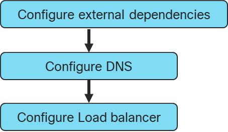
Configure DNS
A domain name service (DNS) is required for access to the cluster as discussed earlier. This should use existing domain name servers for production deployments. A Windows DNS server was used in the validated environment. The configuration for this is shown in the Appendix.
Table 5 Required DNS Entries
| Record |
Destination |
Notes |
|
| Kubernetes API |
api-int.<cluster_name>.<base_name>. |
OpenShift Admin Load Balancer |
Must be resolvable by all external clients and cluster nodes |
| Kubernetes Internal |
api-int.<cluster_name>.<base_name>. |
OpenShift Admin Load Balancer |
Must be resolvable by all cluster nodes |
| Application Routes |
*.apps. <cluster_name>.<base_name>. |
OpenShift Application Ingress |
Must be resolvable by all external clients and cluster nodes |
| Master nodes |
etcd-<index>.<cluster_name>.<base_name>. |
Master nodes |
Must be resolvable by all cluster nodes |
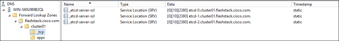
| SSL Server |
_etcd-server-ssl._tcp. <cluster_name>.<base_name>. |
Master nodes |
Refer below. |
| Kubernetes API |
api-int.<cluster_name>.<base_name>. |
OpenShift Admin Load Balancer |
Must be resolvable by all external clients and cluster nodes |
Configure Load Balancer
Before you install OpenShift Container Platform, you must provision two layer-4 load balancers. The API requires one load balancer and the default Ingress Controller needs the second load balancer to provide ingress to applications.
The validated environment used an external load balancer running HAproxy to offer a single-entry point for the many Red Hat OpenShift Container Platform components. Organizations can provide their own currently deployed load balancers if the service already exists.
The load balancer (haproxy) available with the RHEL distribution was used to create the haproxy server. The configuration files used for creating the haproxy server are listed in the Appendix.
To configure the load balancer, follow these steps:
1. Install the haproxy operating system package using the yum or rpm command:
yum install haproxy
2. Update the configuration files (/etc/haproxy/haproxy.cfg), as listed in the Appendix.
3. Start or Restart the haproxy service:
systemctl restart haproxy
systemctl enable haproxy
4. Add the following firewall rules to allow clients connection to access HAProxy server:
firewall-cmd --permanent --add-service=haproxy
firewall-cmd --reload
5. Optionally, the Firewall can be stopped and disabled for system startup using the following commands:
systemctl stop firewalld
systemctl disable firewalld
![]() If your haproxy service does not start and SELinux is enabled, run the following command to allow haproxy to bind to non-standard ports: setsebool -P haproxy_connect_any on
If your haproxy service does not start and SELinux is enabled, run the following command to allow haproxy to bind to non-standard ports: setsebool -P haproxy_connect_any on
6. The output of the following commands should display the status as “Active: active (running)”, without any errors and the load balancer needs to be configured with the values as follows:
| Description |
Incoming Port |
Mode |
Destination |
Dest. Port |
Balance |
| OpenShift Admin |
6443 |
TCP |
Master Nodes |
6443 |
Source |
| OpenShift Installation (Removed once built) |
22623 |
TCP |
Bootstrap and Master Nodes |
22623 |
Source |
| OpenShift Application Ingress |
80 |
TCP |
Worker Nodes |
80 |
Source |
| 443 |
TCP |
Worker Nodes |
443 |
Source |
7. The Status of all the previously installed services can be verified using the following commands before proceeding with the OpenShift Container Platform cluster installation:
systemctl status httpd
systemctl status dhcpd
systemctl status named
systemctl status haproxy
Prepare OCP Nodes
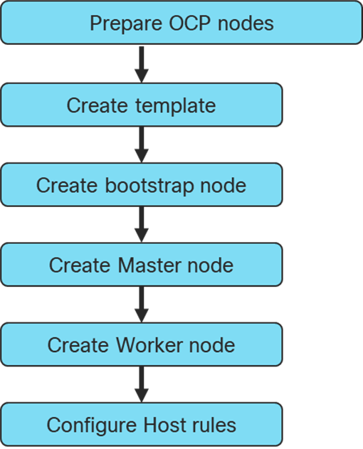
Create Template
Prior to installing the OCP cluster on VMware vSphere, you need to create RHCOS machines on the vSphere hosts.
![]() Terraform was used to create the RHCOS machines using a VM template.
Terraform was used to create the RHCOS machines using a VM template.
To create the VM template using RHCOS OVA, follow these steps:
1. Obtain the RHCOS OVA image from the Product Downloads page on the Red Hat customer portal or the RHCOS image mirror page, https://cloud.Red Hat.com/openshift/install/vsphere/user-provisioned
![]() The RHCOS images might not change with every release of OpenShift Container Platform. You must download an image with the highest version that is less than or equal to the OpenShift Container Platform version that you install. Use the image version that matches your OpenShift Container Platform version if it is available.
The RHCOS images might not change with every release of OpenShift Container Platform. You must download an image with the highest version that is less than or equal to the OpenShift Container Platform version that you install. Use the image version that matches your OpenShift Container Platform version if it is available.
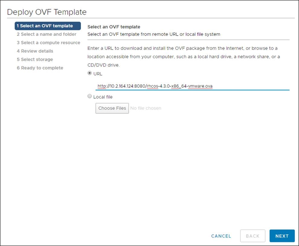
2. The file name contains the OpenShift Container Platform version number in the format rhcos-<version>-vmware.<architecture>.ova. (for example: rhcos-4.3.8-x86_64-vmware.x86_64.ova)
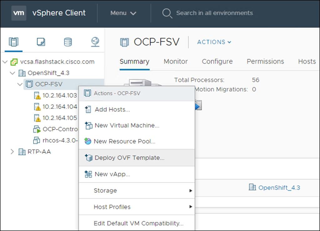
3. In the vSphere Client, create a template for the OVA image.
In the following steps, use the same template for all cluster virtual machines when you provision:
1. From the Hosts and Clusters tab, right-click your cluster’s name <vCenter_Cluster> and click Deploy OVF Template.
2. From the Select an OVF tab, specify the name of the RHCOS OVA file that you downloaded.
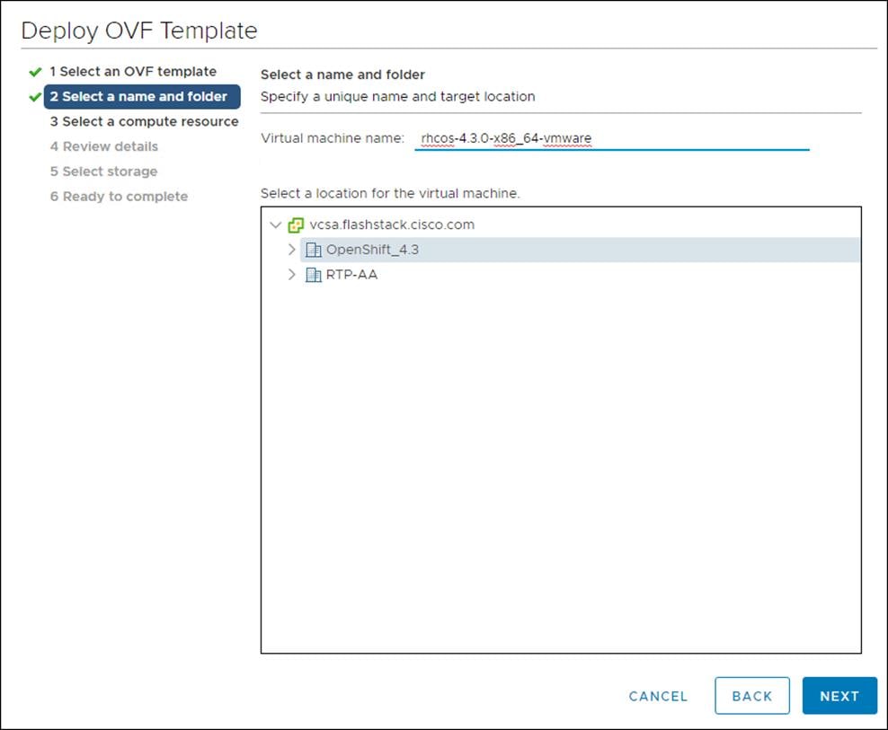
3. From the Select a name and folder tab, set a Virtual machine name, such as RHCOS, click the name of your vSphere cluster.
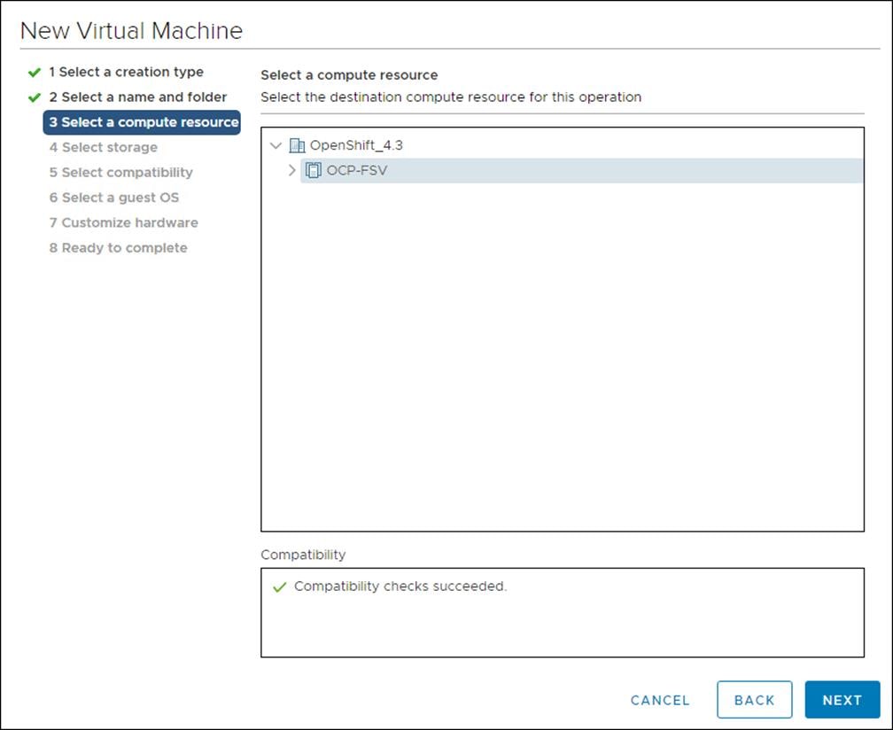
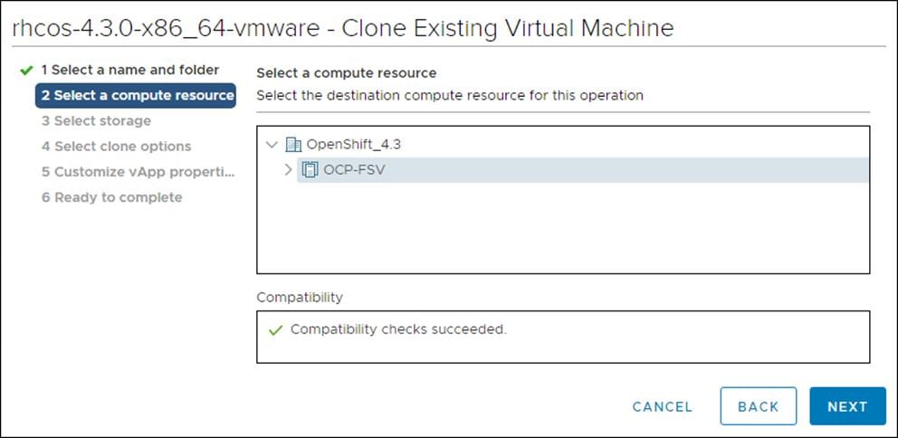
4. From the Select a compute resource tab, click the name of your vSphere cluster.
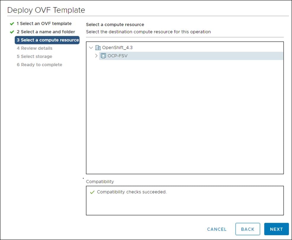
5. Click Next.
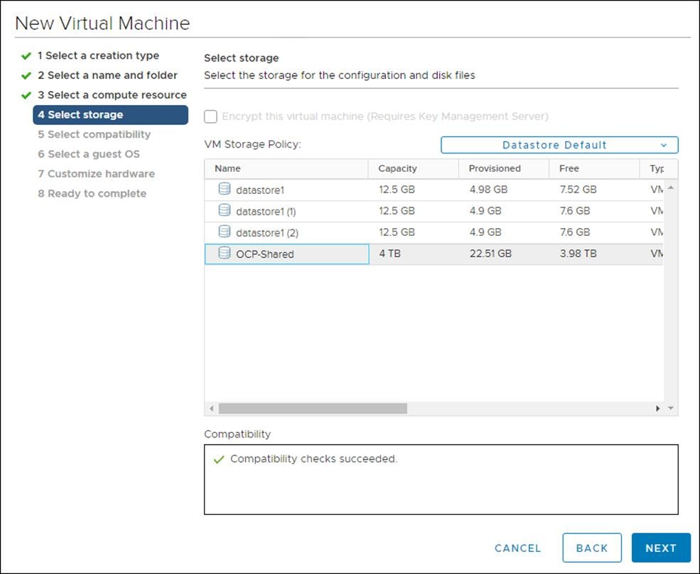
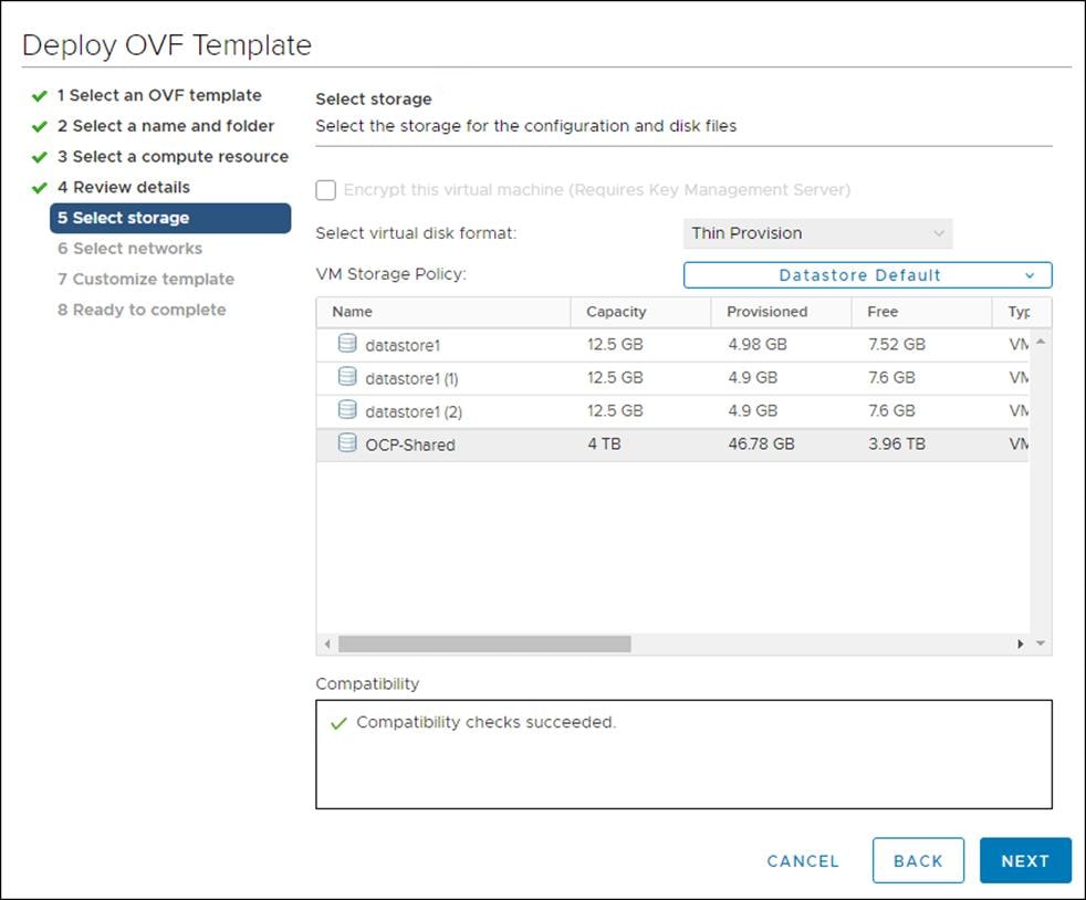
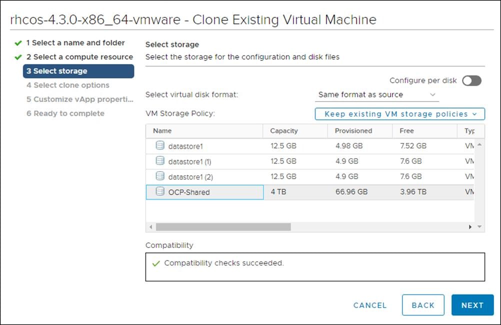
6. From the Select storage tab, configure the storage options for your VM. Select Thin Provision and the datastore <OCP_Infra_1> that you specified in your install-config.yaml file.
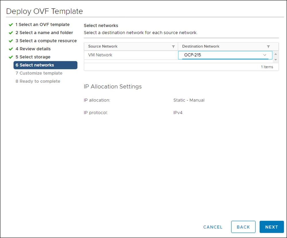
7. From the Select network tab, specify the network <OCC-VLAN> previously configured for the OCP cluster.
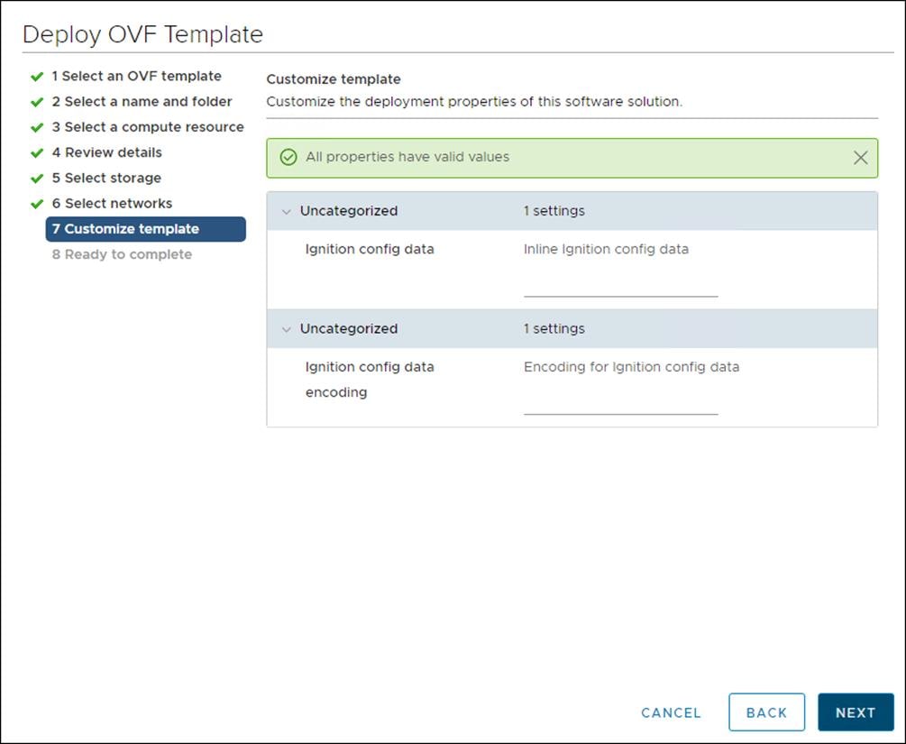
8. Since you will use the same template for all cluster machine types, do not specify the values on the Customize template tab.
9. Review the details and select FINISH if correct.
10. In the vSphere Client, create a folder in your datacenter to store your VMs.
11. Click the VMs and Templates view.
12. Right-click the name of your data center.
13. Click New Folder, then click New VM and Template Folder.
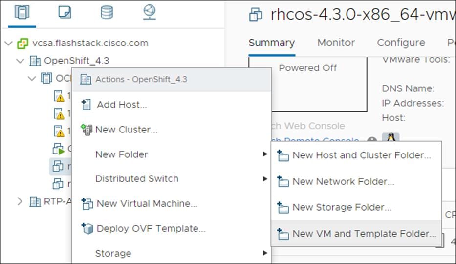
14. In the window that is displayed, enter the folder name. The folder name must match the cluster name that you specified in the install-config.yaml file.

Create Bootstrap Node
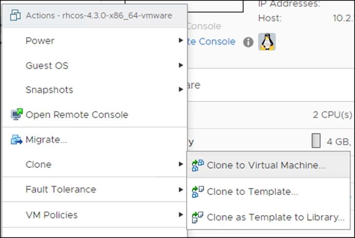
To create the bootstrap node, follow these steps:
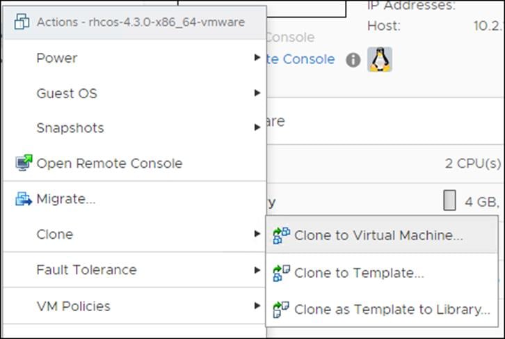
1. Right-click the template’s name and click Clone, then click Clone to Virtual Machine.
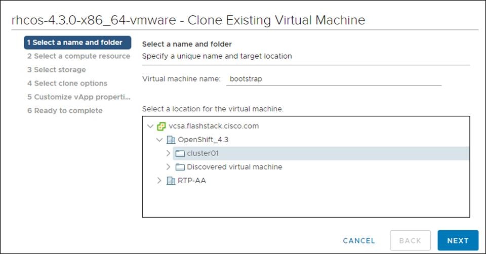
2. On the Select a name and folder tab, specify a name for the VM as bootstrap. Select the name of the folder that you created for the cluster.
3. On the Select a compute resource tab, select the name of a host in your data center.

4. On Select storage, select the datastore specified in the install-config.yaml.

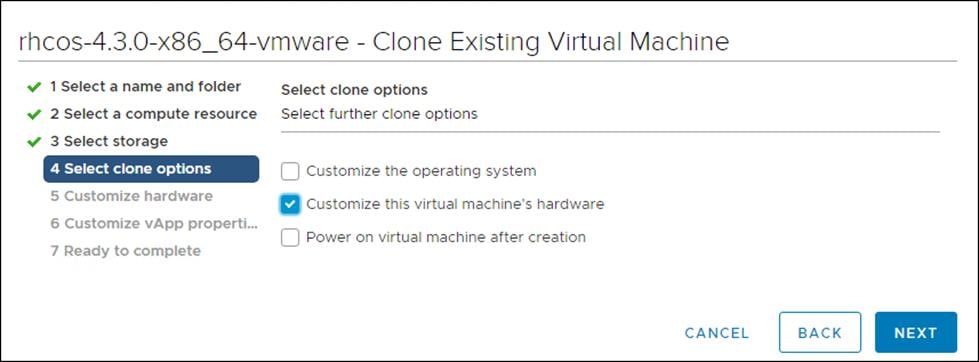
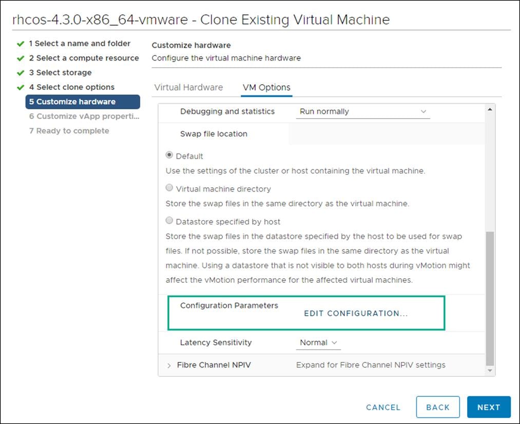
5. On the Select clone options, select Customize this virtual machine’s hardware.
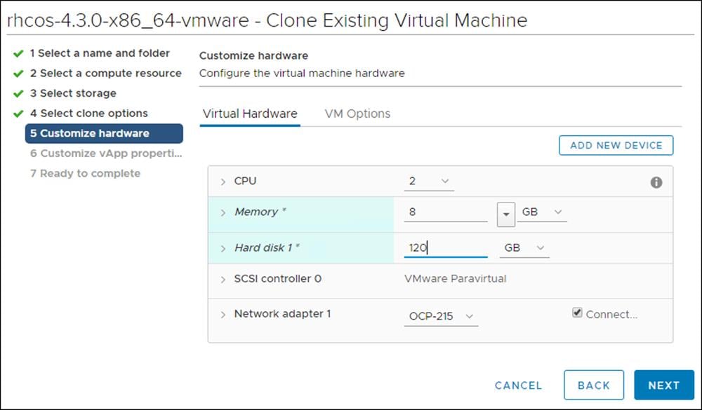
6. Customize the Virtual Hardware for 4 vCPU, 16 GB RAM, and 120 GB Hard disk 1.
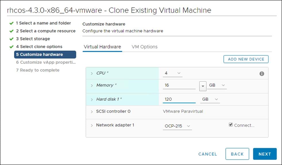
7. On the Customize hardware tab, click VM Options, then click Advanced.
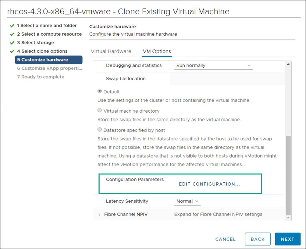
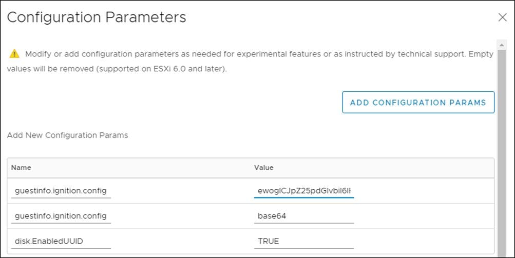
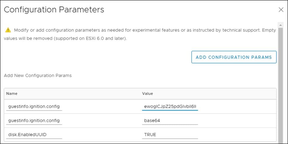
8. Click Edit Configuration then from the Configuration Parameters window, click Add Configuration Params. Define the following parameter names and values:
- guestinfo.ignition.config.data: Paste the contents of the base64-encoded append-bootstrap.64 Ignition config.
- guestinfo.ignition.config.data.encoding: Specify base64.
- disk.EnableUUID: Specify TRUE.
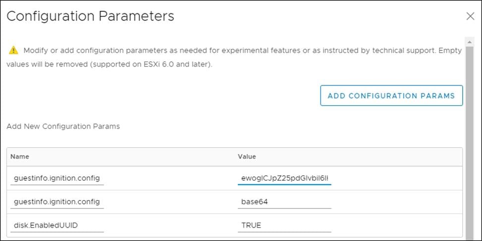
9. Click OK to return to Customize hardware.
10. Click Next to move to Customize vApp properties.
11. Click Next to move to Ready to Complete.
12. Click Finish.
Create Master Node
To create the master node, follow these steps:
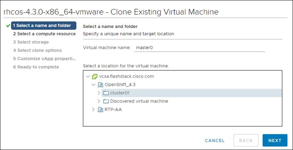
1. Right-click the template’s name and click Clone, then click Clone to Virtual Machine.
2. On the Select a name and folder tab, specify a name for the VM as master<n>. Select the name of the folder that you created for the cluster.
3. On the Select a compute resource tab, select the name of a host in your data center.

4. On Select storage, select the datastore specified in the install-config.yaml.

5. On the Select clone options, select Customize this virtual machine’s hardware.

6. Customize the Virtual Hardware for 4 vCPU, 16 GB RAM, and 120 GB Hard disk 1.

7. On the Customize hardware tab, click VM Options, then click Advanced.
8. Click Edit Configuration, and on the Configuration Parameters window, click Add Configuration Params. Define the following parameter names and values:
- guestinfo.ignition.config.data: Paste the contents of the base64-encoded master.64 Ignition config.
- guestinfo.ignition.config.data.encoding: Specify base64.
- disk.EnableUUID: Specify TRUE.
9. Click OK to return to Customize hardware.
10. Click Next to move to Customize vApp properties.
11. Click Next.
12. Click Finish.
13. Repeat steps 1-12 for Master nodes 0, 1, and 2.
Create Worker Node
To create a worker node, follow these steps:
1. Right-click the template’s name and click Clone and then click Clone to Virtual Machine.
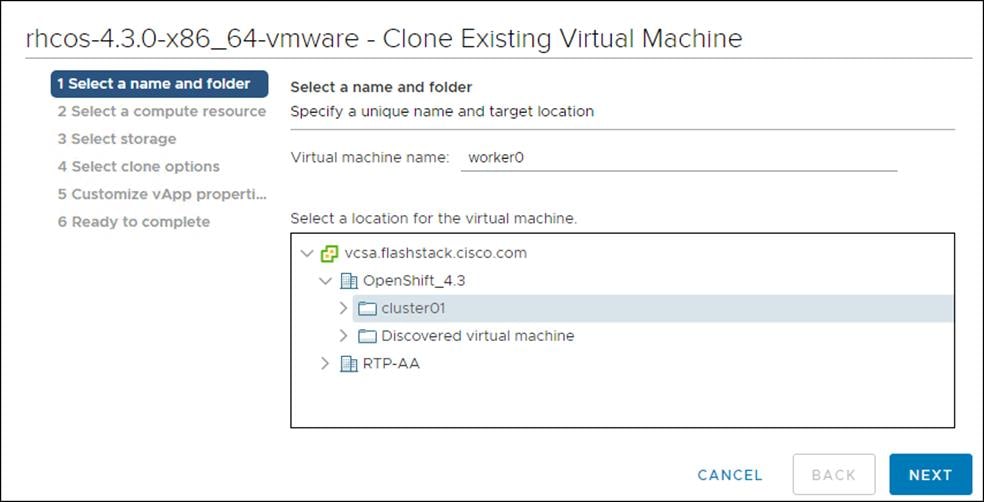
2. From the Select a name and folder tab, specify a name for the VM as worker0. Select the name of the folder that you created for the cluster.
3. From the Select a compute resource tab, select the name of a host in your data center.
4. On Select storage, select the datastore specified in the install-config.yaml.
5. On the Select clone options, select Customize this virtual machine’s hardware.

6. Customize the Virtual Hardware for 2 vCPU, 8 GB RAM, and 120 GB Hard disk 1.
7. On the Customize hardware tab, click VM Options and then click Advanced.

8. Click Edit Configuration and from the Configuration Parameters window, click Add Configuration Params. Define the following parameter names and values:
- guestinfo.ignition.config.data: Paste the contents of the base64-encoded worker.64 Ignition config.
- guestinfo.ignition.config.data.encoding: Specify base64.
- disk.EnableUUID: Specify TRUE.
9. Click OK to return to Customize hardware.
10. Click Next to move to Customize vApp properties.
11. Click Next to move to Ready to Complete.
12. Click Finish.
13. Repeat steps 1-13 for worker nodes 0, 1, 2, and 3.
Update DHCP Records
Bootstrap, Master, and Worker nodes need to be assigned the correct IP addresses on boot. DHCP reservations need to be configured to match the MAC addresses of these nodes. To obtain the MAC address for each VM, follow these steps:
1. Select the Virtual Machine.
2. Under VM Hardware, expand Network Adapter 1.
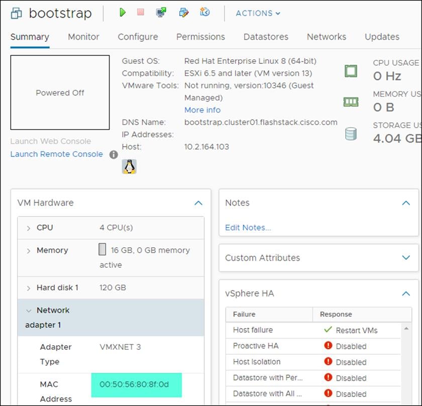
3. Record the value of the MAC Address and update the DHCP record for this host.
4. Repeat steps 1-3 for all Bootstrap, Master, and Worker nodes.
Configure Host Rules
A Host rule will be created to ensure that Master nodes are running on different physical host. This is done to ensure that the high availability provided by using three (3) master nodes is also provided at the hardware layer.
To configure the host rules, follow these steps:
1. Select the OCP Cluster.
2. Select Configure.
3. Select VM/Host Rules.
4. Select Add.
5. Provide a Name, set type to Separate Virtual Machines, select Add.
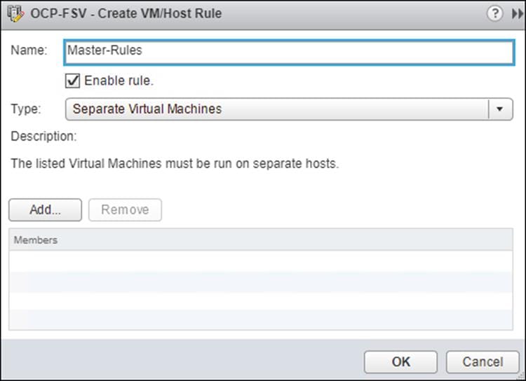
6. Add Master Nodes 0-2.
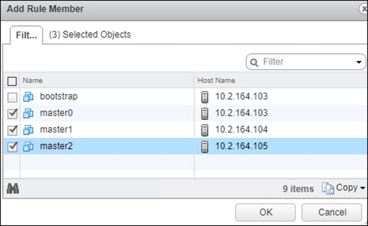
7. Click OK.
8. Click OK.
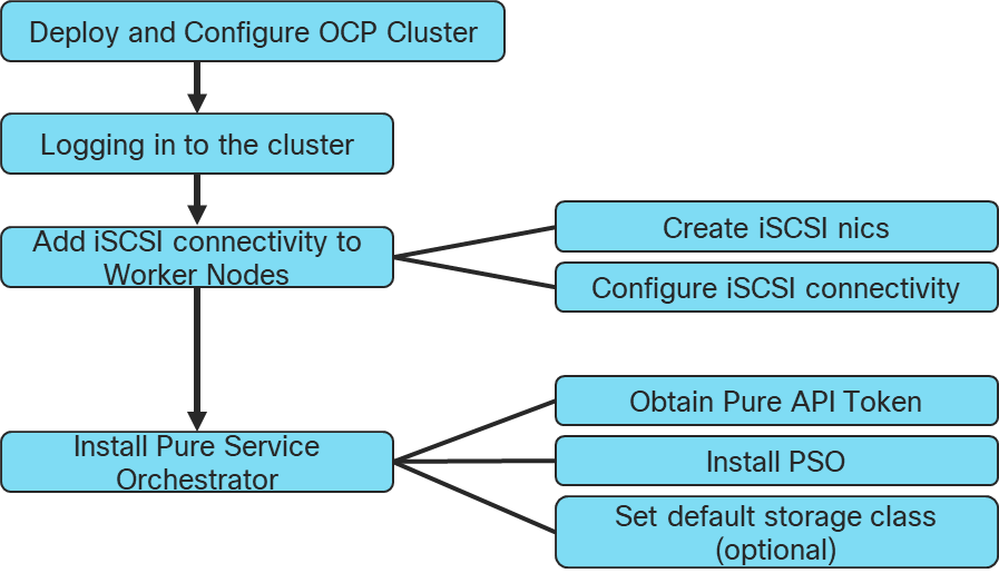
Deploy and Configure OpenShift Container Platform Cluster
This section explains the deployment of the OpenShift Container Platform cluster and the post deployment configuration to install Pure Service Orchestrator to provide Persistent Volumes (PV) and Persistent Volume Claims (PVC).
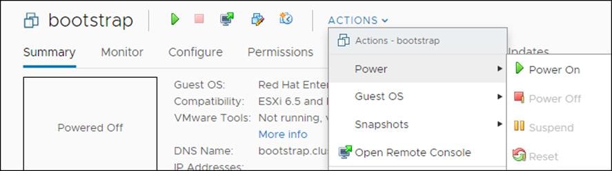
Power on Nodes
To power on nodes, follow these steps:
1. Select the bootstrap VM. Click Actions > Power > Power On. Repeat this step for all master and worker nodes.
2. Monitor cluster creation.
$./openshift-install --dir=<installation_directory> wait-for bootstrap-complete --log-level=info
INFO It is now safe to remove the bootstrap resource
Log into the Cluster
You can log into your cluster as a default system user by exporting the cluster kubeconfig file. The kubeconfig file contains information about the cluster that is used by the CLI to connect a client to the correct cluster and API server. The file is specific to a cluster and is created during OpenShift Container Platform installation.
To log into the cluster, follow these steps:
1. Export the kubeadmin credentials:
$ export KUBECONFIG=<installation_directory>/auth/kubeconfig
2. Verify you can run oc commands:
$ oc whoami
system:admin
Complete OCP Installation
To complete the OCP installation, follow these steps:
1. Verify the cluster components are online:
$ watch -n5 oc get clusteroperators
NAME VERSION AVAILABLE PROGRESSING DEGRADED SINCE
authentication 4.3.0 True False False 10m
cloud-credential 4.3.0 True False False 22m
cluster-autoscaler 4.3.0 True False False 21m
console 4.3.0 True False False 10m
dns 4.3.0 True False False 21m
image-registry 4.3.0 True False False 16m
ingress 4.3.0 True False False 16m
kube-apiserver 4.3.0 True False False 19m
kube-controller-manager 4.3.0 True False False 18m
kube-scheduler 4.3.0 True False False 22m
machine-api 4.3.0 True False False 22m
machine-config 4.3.0 True False False 18m
marketplace 4.3.0 True False False 18m
monitoring 4.3.0 True False False 18m
network 4.3.0 True False False 16m
node-tuning 4.3.0 True False False 21m
openshift-apiserver 4.3.0 True False False 21m
openshift-controller-manager 4.3.0 True False False 17m
openshift-samples 4.3.0 True False False 14m
operator-lifecycle-manager 4.3.0 True False False 21m
operator-lifecycle-manager-catalog 4.3.0 True False False 21m
service-ca 4.3.0 True False False 21m
service-catalog-apiserver 4.3.0 True False False 16m
service-catalog-controller-manager 4.3.0 True False False 16m
storage 4.3.0 True False False 16m
2. Confirm Kubernetes API server is communicating with the Pods:
$ oc get pods --all-namespaces
NAMESPACE NAME READY
openshift-apiserver-operator openshift-apiserver-operator-85cb746d55-zqhs8 1/1
openshift-apiserver apiserver-67b9g 1/1
openshift-apiserver apiserver-ljcmx 1/1
openshift-apiserver apiserver-z25h4 1/1
openshift-authentication-operator authentication-operator-69d5d8bf84-vh2n8 1/1
...
Add iSCSI Network Adapters to Worker Nodes
To add iSCSI network adapter on each worker node, follow these steps:
1. Access FlashSTack vCenter.
2. Right-click a worker node in the inventory and select Edit Settings.
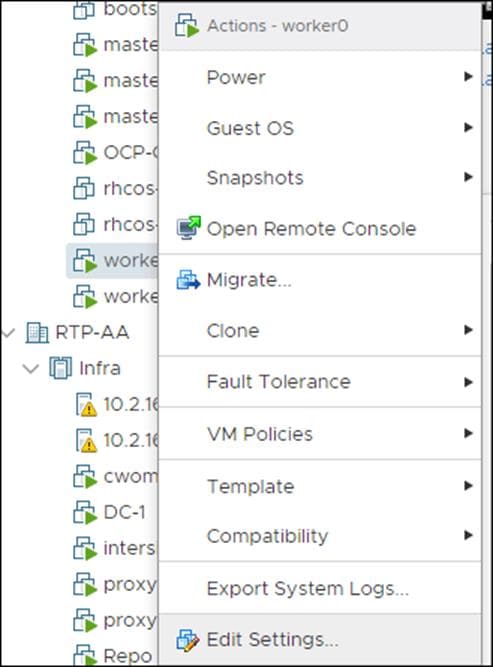
3. Click ADD NEW DEVICE.

4. Select Network Adapter from the drop-down list.
The new network adapter appears at the bottom of the device list.
5. Expand New Network and check the boxes against both Connected and Connected at power on.
6. From the drop-down list next to the New Network label, select the iSCSI-A port group.

7. Click OK.
8. Click ADD NEW DEVICE again.
9. Select Network Adapter from the drop-down list.
10. The new network adapter appears at the bottom of the device list.
11. Expand New Network and check the boxes against Connected and Connected at power on.
12. From the drop-down list next to the New Network label, select the iSCSI-B port group.

13. Repeat steps 1-12 for all the worker nodes.
14. Note down the MAC addresses of the newly created adapters on all the worker nodes. The MAC addresses will be used to assign IP addresses from storage VLAN to the adapters using machine config file.
To configure the new network adapters through defining new machineconfig, follow these steps:
1. Create a new ifcfg text file which defines a HWADDR which corresponds to the MAC address of the adapter to be configured. Create one file for each adapter on all worker nodes.
HWADDR=00:50:56:98:9f:ee
TYPE=Ethernet
BOOTPROTO=none
IPADDR=192.168.101.202
PREFIX=24
ONBOOT=yes
GATEWAY=192.168.101.254
MTU=9000
2. Run the following command to base64 encode the ifcfg file(s).
$ cat ifcfg-file | base64 -w 0
SFdBRERSPTAwOjUwOjU2Ojk4OjlmOmVlClRZUEU9RXRoZXJuZXQKQk9PVFBST1RPPW5vbmUKSVBBRERSPTEwLjI5LjE2Mi4yMDEKUFJFRklYPTI0CkROUzE9MTAuMS4xNjIuMgpPTkJPT1Q9eWVzCkdBVEVXQVk9MTAuMjkuMTYyLjEK
3. Create a new machineconfig yaml file which contains the base64 encoded ifcfg files.
4. Append the base64 content after data:text/plain;charset=utf-8;base64,
5. Create a new file object for each adapter which needs to be configured.
{
"filesystem": "root",
"path": "/etc/sysconfig/network-scripts/ifcfg-compute-1-sn",
"contents": {
"source": "data:text/plain;charset=utf-8;base64,SFdBRERSPTAwOjUwOjU2Ojk4OjUwOjY3ClRZUEU9RXRoZXJuZXQKQk9PVFBST1RPPW5vbmUKSVBBRERSPTEwLjI5LjE2Mi4yMDIKUFJFRklYPTI0CkROUzE9MTAuMS4xNjIuMgpPTkJPT1Q9eWVzCkdBVEVXQVk9MTAuMjkuMTYyLjEK",
"verification": {}
},
"mode": 420
}
6. The following is an example of how to configure two network adapters on each worker node in a cluster consisting of four worker nodes. A file was created with the name the-machine-config and the contents were updated as follows:
{
"apiVersion": "machineconfiguration.openshift.io/v1",
"kind": "MachineConfig",
"metadata": {
"labels": {
"machineconfiguration.openshift.io/role": "worker"
},
"name": "99-storage-network"
},
"spec": {
"config":
{
"ignition": {
"config": {},
"timeouts": {},
"version": "2.1.0"
},
"networkd": {},
"passwd": {},
"storage": {
"files": [
{
"filesystem": "root",
"path": "/etc/sysconfig/network-scripts/ifcfg-compute-01-sn",
"contents": {
"source": "data:text/plain;charset=utf-8;base64,SFdBRERSPTAwOjUwOjU2Ojk4OjE4OmRkClRZUEU9RXRoZXJuZXQKQk9PVFBST1RPPW5vbmUKSVBBRERSPTEwLjI5LjE2MS4yMDEKUFJFRklYPTI0CkROUzE9MTAuMS4xNjIuMgpPTkJPT1Q9eWVzCkdBVEVXQVk9MTAuMjkuMTYxLjEK",
"verification": {}
},
"mode": 420
},
{
"filesystem": "root",
"path": "/etc/sysconfig/network-scripts/ifcfg-compute-02-sn",
"contents": {
"source": "data:text/plain;charset=utf-8;base64,SFdBRERSPTAwOjUwOjU2Ojk4OjY3OmUzClRZUEU9RXRoZXJuZXQKQk9PVFBST1RPPW5vbmUKSVBBRERSPTEwLjI5LjE2Mi4yMDEKUFJFRklYPTI0CkROUzE9MTAuMS4xNjIuMgpPTkJPT1Q9eWVzCkdBVEVXQVk9MTAuMjkuMTYyLjEK",
"verification": {}
},
"mode": 420
},
{
"filesystem": "root",
"path": "/etc/sysconfig/network-scripts/ifcfg-compute-11-sn",
"contents": {
"source": "data:text/plain;charset=utf-8;base64,SFdBRERSPTAwOjUwOjU2Ojk4OmNhOmYxClRZUEU9RXRoZXJuZXQKQk9PVFBST1RPPW5vbmUKSVBBRERSPTEwLjI5LjE2MS4yMDIKUFJFRklYPTI0CkROUzE9MTAuMS4xNjIuMgpPTkJPT1Q9eWVzCkdBVEVXQVk9MTAuMjkuMTYxLjEK",
"verification": {}
},
"mode": 420
},
{
"filesystem": "root",
"path": "/etc/sysconfig/network-scripts/ifcfg-compute-12-sn",
"contents": {
"source": "data:text/plain;charset=utf-8;base64,SFdBRERSPTAwOjUwOjU2Ojk4OmZjOjJkClRZUEU9RXRoZXJuZXQKQk9PVFBST1RPPW5vbmUKSVBBRERSPTEwLjI5LjE2Mi4yMDIKUFJFRklYPTI0CkROUzE9MTAuMS4xNjIuMgpPTkJPT1Q9eWVzCkdBVEVXQVk9MTAuMjkuMTYyLjEK",
"verification": {}
},
"mode": 420
},
{
"filesystem": "root",
"path": "/etc/sysconfig/network-scripts/ifcfg-compute-21-sn",
"contents": {
"source": "data:text/plain;charset=utf-8;base64,SFdBRERSPTAwOjUwOjU2Ojk4OmY1OjhlClRZUEU9RXRoZXJuZXQKQk9PVFBST1RPPW5vbmUKSVBBRERSPTEwLjI5LjE2MS4yMDMKUFJFRklYPTI0CkROUzE9MTAuMS4xNjIuMgpPTkJPT1Q9eWVzCkdBVEVXQVk9MTAuMjkuMTYxLjEK",
"verification": {}
},
"mode": 420
},
{
"filesystem": "root",
"path": "/etc/sysconfig/network-scripts/ifcfg-compute-22-sn",
"contents": {
"source": "data:text/plain;charset=utf-8;base64,SFdBRERSPTAwOjUwOjU2Ojk4OjkwOjVkClRZUEU9RXRoZXJuZXQKQk9PVFBST1RPPW5vbmUKSVBBRERSPTEwLjI5LjE2Mi4yMDMKUFJFRklYPTI0CkROUzE9MTAuMS4xNjIuMgpPTkJPT1Q9eWVzCkdBVEVXQVk9MTAuMjkuMTYyLjEK",
"verification": {}
},
"mode": 420
},
{
"filesystem": "root",
"path": "/etc/sysconfig/network-scripts/ifcfg-compute-31-sn",
"contents": {
"source": "data:text/plain;charset=utf-8;base64,SFdBRERSPTAwOjUwOjU2Ojk4OmQ4OmU1ClRZUEU9RXRoZXJuZXQKQk9PVFBST1RPPW5vbmUKSVBBRERSPTEwLjI5LjE2MS4yMDQKUFJFRklYPTI0CkROUzE9MTAuMS4xNjIuMgpPTkJPT1Q9eWVzCkdBVEVXQVk9MTAuMjkuMTYxLjEK",
"verification": {}
},
"mode": 420
},
{
"filesystem": "root",
"path": "/etc/sysconfig/network-scripts/ifcfg-compute-32-sn",
"contents": {
"source": "data:text/plain;charset=utf-8;base64,SFdBRERSPTAwOjUwOjU2Ojk4OjgyOjY2ClRZUEU9RXRoZXJuZXQKQk9PVFBST1RPPW5vbmUKSVBBRERSPTEwLjI5LjE2Mi4yMDQKUFJFRklYPTI0CkROUzE9MTAuMS4xNjIuMgpPTkJPT1Q9eWVzCkdBVEVXQVk9MTAuMjkuMTYyLjEK",
"verification": {}
},
"mode": 420
}
]
},
"systemd": {}
},
"osImageURL": ""
}
}
7. Apply the machineconfig by running the following command:
$ oc apply -f the-machine-config
machineconfig.machineconfiguration.openshift.io/99-storage-network created
8. Wait for all impacted nodes to restart.
iSCSI Connectivity Configuration
To configure the iSCSI connectivity, follow these steps for each worker node:
1. Obtain the iSCSI initiator name in the /etc/iscsi/initiatorname.iscsi file:
[core@worker-0 ~]$ sudo cat /etc/iscsi/initiatorname.iscsi
InitiatorName=iqn.1994-05.com.redhat:783fd64d1a78
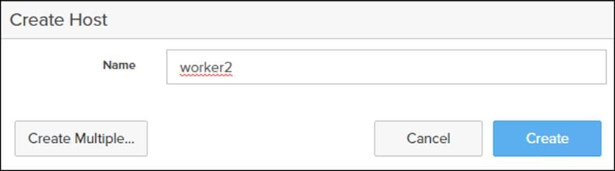
2. Add the worker node as a host on the Pure Storage FlashArray//X via the Web console.
3. Select Storage -> Host.
4. Under host select + to create host.
5. Enter a host name and click Create.
6. Select the newly created host for the Hosts list.
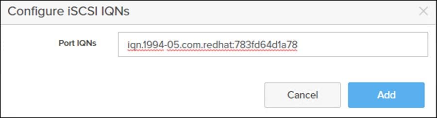
7. Select Configured IQNs… under Host Ports.
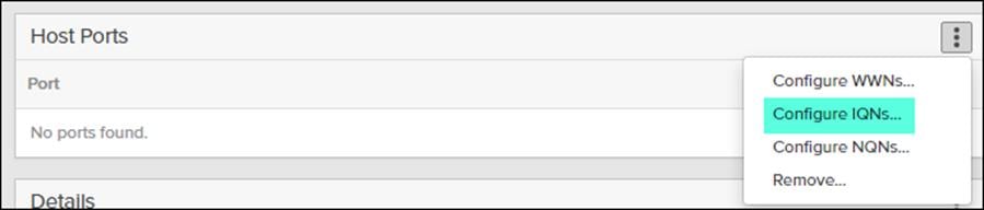
8. Enter the IQN from the previous step and click Add.
9. For the iSCSI initd script startup, set a session to automatic in /etc/iscsi/iscsid.conf: “node.startup = automatic”
10. Enable multipathd:
[core@worker-0 ~]$ sudo /sbin/mpathconf –enable
[core@worker-0 ~]$ sudo systemctl enable multipathd
[core@worker-0 ~]$ sudo systemctl start multipathd
Obtain FlashArray//X API Token
To obtain the FlashArray//X API token, follow these steps:
1. Log into FlashArray//X Web Console.
2. Click Settings > Users.
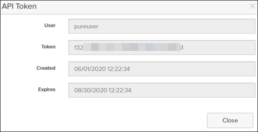
3. Click the gear icon from your admin user and select Show API Token…
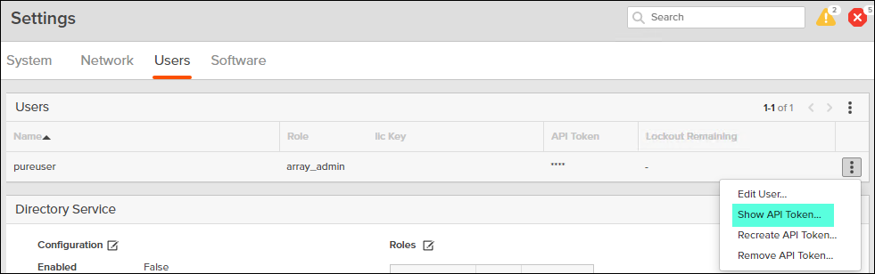
4. Record the API Token:
Install Pure Service Orchestrator (PSO)
Pure Service Orchestrator installation must be run from a node that has the OpenShift Command-line interface installed. To install PSO, follow these steps:
1. Clone the PSO installation files:
$ git clone https://github.com/purestorage/helm-charts.git
2. Configure values.yaml located in ../helm-charts/operator-csi-plugin/ to match your FlashArray settings:
$ vi values.yaml
…
# support k8s or openshift
orchestrator:
# name is either 'k8s' or 'openshift'
name: openshift
…
arrays specify what storage arrays should be managed by the plugin, this is
# required to be set upon installation. For FlashArrays you must set the "MgmtEndPoint"
# and "APIToken", and for FlashBlades you need the additional "NfsEndPoint" parameter.
# The labels are optional, and can be any key-value pair for use with the "fleet"
# provisioner. An example is shown below:
arrays:
FlashArrays:
- MgmtEndPoint: "10.2.164.45"
APIToken: "132#####-####-####-####-########d51"
Labels:
topology.purestorage.com/rack: "AA-8"
topology.purestorage.com/env: "FlashStack"
![]() The values file used for this validation is included in the Appendix.
The values file used for this validation is included in the Appendix.
3. Install PSO:
$ ./install.sh --namespace=pure-csi-operator --orchestrator=openshift -f values.yaml
4. Configured RBAC rules for PSO Operator:
$ oc adm policy add-scc-to-group privileged system:serviceaccounts:pure-csi-operator
![]() For more information about Pure Service Orchestrator, go to: https://github.com/purestorage/helm-charts/tree/master/operator-csi-plugin
For more information about Pure Service Orchestrator, go to: https://github.com/purestorage/helm-charts/tree/master/operator-csi-plugin
Set Pure-Block as the Default Storage Class (Optional)
To set the Pure-Block as the default storage class, follow these steps:
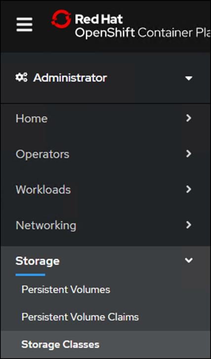
1. Log into OpenShift Cluster Web Console.
2. Select Administrator.
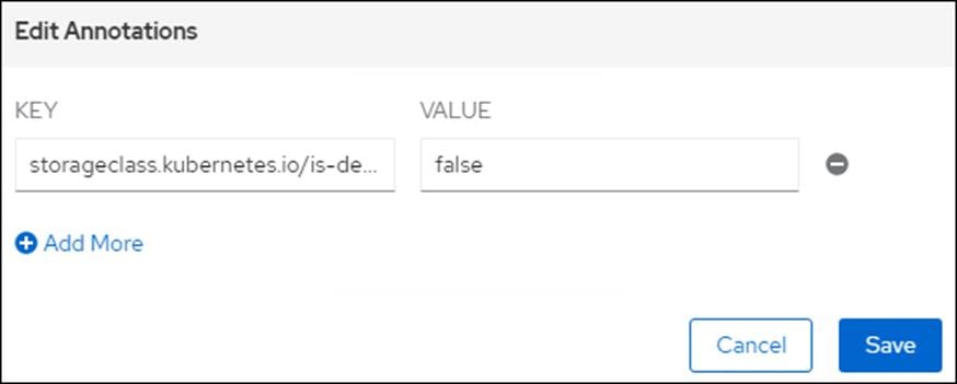
3. Click Storage >Storage Class.
4. Select the Edit Annotations for Storage Class thin.
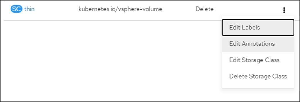
5. Set storageclass.kubernetes.io/is-default-class to false.
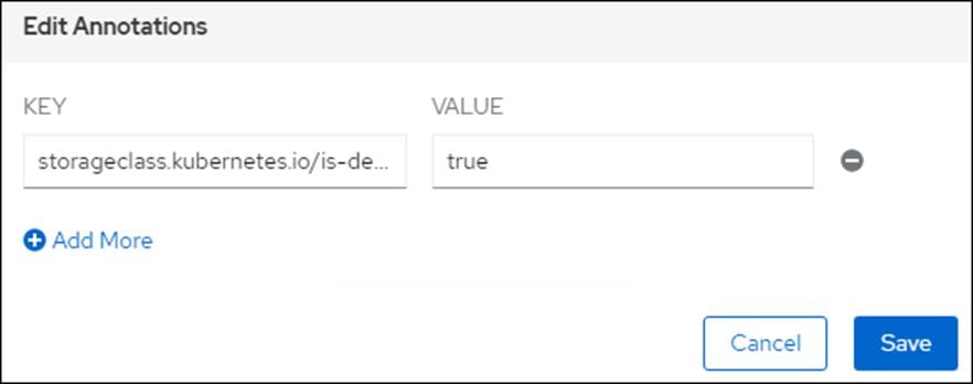
6. Click Edit Annotations for Storage Class pure-block.
7. Set storageclass.kubernetes.io/is-default-class to true.
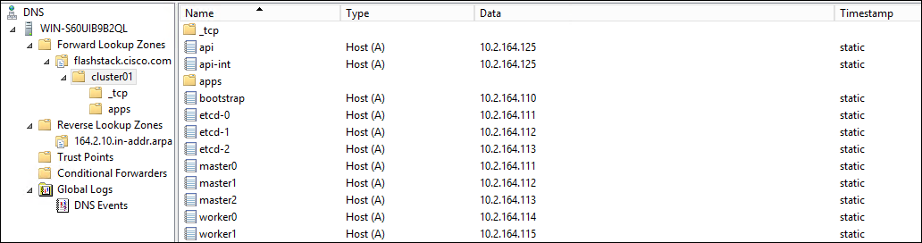
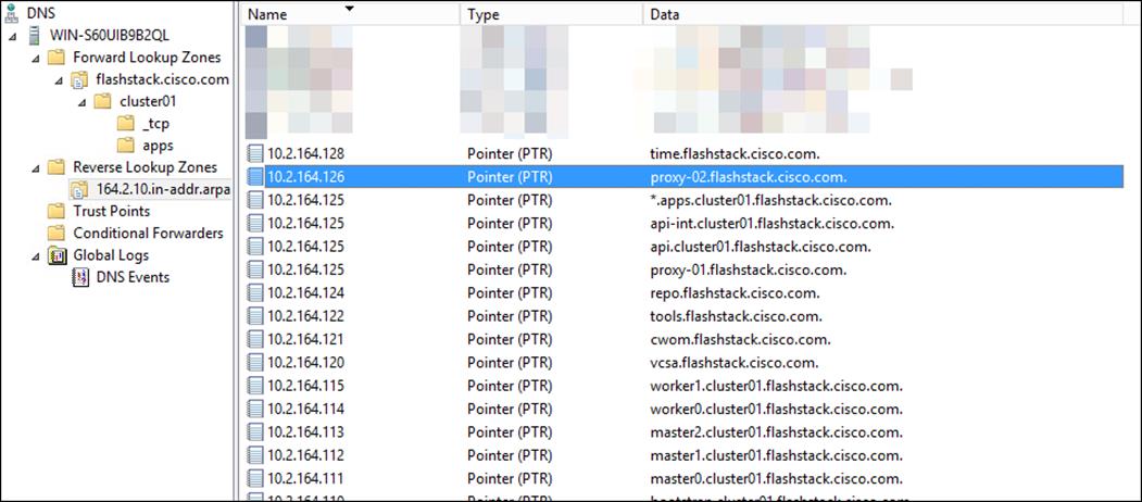
DNS Entries
The following are screenshots showing the DNS entries used in the validation of this deployment
Load Balancer Configuration
The following is the /etc/haproxy/haproxy.cfg file used in the validation of this deployment:
[root@loadbalancer ~]# cat /etc/haproxy/haproxy.cfg
#---------------------------------------------------------------------
# Example configuration for a possible web application. See the
# full configuration options online.
#
# http://haproxy.1wt.eu/download/1.4/doc/configuration.txt
#
#---------------------------------------------------------------------
#---------------------------------------------------------------------
# Global settings
#---------------------------------------------------------------------
global
# to have these messages end up in /var/log/haproxy.log you will
# need to:
#
# 1) configure syslog to accept network log events. This is done
# by adding the '-r' option to the SYSLOGD_OPTIONS in
# /etc/sysconfig/syslog
#
# 2) configure local2 events to go to the /var/log/haproxy.log
# file. A line like the following can be added to
# /etc/sysconfig/syslog
#
# local2.* /var/log/haproxy.log
#
log 127.0.0.1 local2
chroot /var/lib/haproxy
pidfile /var/run/haproxy.pid
maxconn 4000
user haproxy
group haproxy
daemon
# turn on stats unix socket
stats socket /var/lib/haproxy/stats
# utilize system-wide crypto-policies
# ssl-default-bind-ciphers PROFILE=SYSTEM
# ssl-default-server-ciphers PROFILE=SYSTEM
#---------------------------------------------------------------------
# common defaults that all the 'listen' and 'backend' sections will
# use if not designated in their block
#---------------------------------------------------------------------
defaults
mode tcp
log global
option httplog
option dontlognull
# option http-server-close
# option forwardfor except 127.0.0.0/8
option redispatch
retries 3
timeout http-request 10s
timeout queue 1m
timeout connect 10s
timeout client 1m
timeout server 1m
timeout http-keep-alive 10s
timeout check 10s
maxconn 3000
#---------------------------------------------------------------------
# main frontend which proxys to the backends
#---------------------------------------------------------------------
frontend openshift-api-server
bind *:6443
default_backend openshift-api-server
mode tcp
option tcplog
backend openshift-api-server
balance source
mode tcp
server bootstrap 10.2.164.110:6443 check
server master0 10.2.164.111:6443 check
server master1 10.2.164.112:6443 check
server master2 10.2.164.113:6443 check
frontend machine-config-server
bind *:22623
default_backend machine-config-server
mode tcp
option tcplog
backend machine-config-server
balance source
mode tcp
server bootstrap 10.2.164.110:22623 check
server master0 10.2.164.111:22623 check
server master1 10.2.164.112:22623 check
server master2 10.2.164.113:22623 check
frontend ingress-http
bind *:80
default_backend ingress-http
mode tcp
option tcplog
backend ingress-http
balance source
mode tcp
server worker0 10.2.164.114:80 check
server worker1 10.2.164.115:80 check
frontend ingress-https
bind *:443
default_backend ingress-https
mode tcp
option tcplog
backend ingress-https
balance source
mode tcp
server worker0 10.2.164.114:443 check
server worker1 10.2.164.115:443 check
Pure Service Orchestrator Values Entries
The following is the /helm-charts/operator-csi-plugin/values.yaml file used in the validation of this deployment:
[root@OCP-Controller ~]# cat helm-charts/operator-csi-plugin/values.yaml
# Default values for csi-plugin.
# This is a YAML-formatted file.
# Declare variables to be passed into your templates.
image:
name: purestorage/k8s
tag: 5.2.0
pullPolicy: Always
csi:
provisioner:
image:
name: quay.io/k8scsi/csi-provisioner
pullPolicy: Always
snapshotter:
image:
name: quay.io/k8scsi/csi-snapshotter
pullPolicy: Always
clusterDriverRegistrar:
image:
name: quay.io/k8scsi/csi-cluster-driver-registrar
pullPolicy: Always
nodeDriverRegistrar:
image:
name: quay.io/k8scsi/csi-node-driver-registrar
pullPolicy: Always
livenessProbe:
image:
name: quay.io/k8scsi/livenessprobe
pullPolicy: Always
# this option is to enable/disable the debug mode of this app
# for pure-csi-driver
app:
debug: false
# do you want to set pure as the default storageclass?
storageclass:
isPureDefault: false
# set the type of backend you want for the 'pure' storageclass
# pureBackend: file
# specify the service account name for this app
clusterrolebinding:
serviceAccount:
name: pure
# support ISCSI or FC, not case sensitive
flasharray:
sanType: ISCSI
defaultFSType: xfs
defaultFSOpt: "-q"
defaultMountOpt: ""
preemptAttachments: "true"
iSCSILoginTimeout: 20
iSCSIAllowedCIDR: ""
flashblade:
snapshotDirectoryEnabled: "false"
# there are two namespaces for this app
# 1. namespace.pure is the backend storage namespace where volumes/shares/etc
# will be created.
namespace:
pure: k8s
# support k8s or openshift
orchestrator:
# name is either 'k8s' or 'openshift'
name: openshift
# arrays specify what storage arrays should be managed by the plugin, this is
# required to be set upon installation. For FlashArrays you must set the "MgmtEndPoint"
# and "APIToken", and for FlashBlades you need the additional "NfsEndPoint" parameter.
# The labels are optional, and can be any key-value pair for use with the "fleet"
# provisioner. An example is shown below:
arrays:
FlashArrays:
- MgmtEndPoint: "10.2.164.45"
APIToken: "1327####-####-####-####-########d51"
Labels:
topology.purestorage.com/rack: "AA-8"
topology.purestorage.com/env: "FlashStack"
# - MgmtEndPoint: "1.2.3.5"
# APIToken: "b526a4c6-18b0-a8c9-1afa-3499293574bb"
#FlashBlades:
# - MgmtEndPoint: "1.2.3.6"
# APIToken: "T-c4925090-c9bf-4033-8537-d24ee5669135"
# NfsEndPoint: "1.2.3.7"
# Labels:
# topology.purestorage.com/rack: "7b"
# topology.purestorage.com/env: "dev"
# - MgmtEndPoint: "1.2.3.8"
# APIToken: "T-d4925090-c9bf-4033-8537-d24ee5669135"
# NfsEndPoint: "1.2.3.9"
# Labels:
# topology.purestorage.com/rack: "6a"
mounter:
# These values map directly to yaml in the daemonset spec, see the kubernetes docs for info
nodeSelector: {}
# disktype: ssd
# These values map directly to yaml in the daemonset spec, see the kubernetes docs for info
tolerations: []
# - operator: Exists
# These values map directly to yaml in the daemonset spec, see the kubernetes docs for info
affinity: {}
# nodeAffinity:
# requiredDuringSchedulingIgnoredDuringExecution:
# nodeSelectorTerms:
# - matchExpressions:
# - key: e2e-az-NorthSouth
# operator: In
# values:
# - e2e-az-North
# - e2e-az-South
provisioner:
# These values map directly to yaml in the deployment spec, see the kubernetes docs for info
nodeSelector: {}
# disktype: ssd
# These values map directly to yaml in the deployment spec, see the kubernetes docs for info
tolerations: []
# - operator: Exists
# These values map directly to yaml in the deployment spec, see the kubernetes docs for info
affinity: {}
# nodeAffinity:
# requiredDuringSchedulingIgnoredDuringExecution:
# nodeSelectorTerms:
# - matchExpressions:
# - key: e2e-az-NorthSouth
# operator: In
# values:
# - e2e-az-North
# - e2e-az-South
Allen Clark, Technical Marketing Engineer, Cisco Systems, Inc.
Allen Clark has over 16 years of experience working with enterprise storage and data center technologies. As a member of various organizations within Cisco, Allen has worked with hundreds of customers on implementation and support of compute and storage products. Allen holds a bachelor’s degree in Computer Science from North Carolina State University and is a dual Cisco Certified Internetwork Expert (CCIE 39519, Storage Networking and Data Center)
Acknowledgements
For their support and contribution to the design, validation, and creation of this Cisco Validated Design, the authors would like to thank:
· Sreeni Edula, Technical Marketing Engineer, Cisco Systems, Inc.
· Brian Everitt, Technical Marketing Engineer, Cisco Systems, Inc.
· Craig Waters, Solutions Architecture / Product Management, Pure Storage, Inc.
· Simon Dodsley, Principle Field Solutions Architect, Pure Storage, Inc.