Cisco and Hitachi Adaptive Solutions for SAP HANA TDI with Scale-Out Storage
Available Languages

Cisco and Hitachi Adaptive Solutions for SAP HANA TDI with Scale-Out Storage
Deployment Guide for SAP HANA Scale-Up and Scale-Out Converged Infrastructure with SUSE Linux Enterprise for SAP Applications 15 and Red Hat Enterprise Linux for SAP HANA 7.6
Published: December 11, 2019
Updated: February 7, 2020

About the Cisco Validated Design Program
The Cisco Validated Design (CVD) program consists of systems and solutions designed, tested, and documented to facilitate faster, more reliable, and more predictable customer deployments. For more information, go to:
http://www.cisco.com/go/designzone.
ALL DESIGNS, SPECIFICATIONS, STATEMENTS, INFORMATION, AND RECOMMENDATIONS (COLLECTIVELY, "DESIGNS") IN THIS MANUAL ARE PRESENTED "AS IS," WITH ALL FAULTS. CISCO AND ITS SUPPLIERS DISCLAIM ALL WARRANTIES, INCLUDING, WITHOUT LIMITATION, THE WARRANTY OF MERCHANTABILITY, FITNESS FOR A PARTICULAR PURPOSE AND NONINFRINGEMENT OR ARISING FROM A COURSE OF DEALING, USAGE, OR TRADE PRACTICE. IN NO EVENT SHALL CISCO OR ITS SUPPLIERS BE LIABLE FOR ANY INDIRECT, SPECIAL, CONSEQUENTIAL, OR INCIDENTAL DAMAGES, INCLUDING, WITHOUT LIMITATION, LOST PROFITS OR LOSS OR DAMAGE TO DATA ARISING OUT OF THE USE OR INABILITY TO USE THE DESIGNS, EVEN IF CISCO OR ITS SUPPLIERS HAVE BEEN ADVISED OF THE POSSIBILITY OF SUCH DAMAGES.
THE DESIGNS ARE SUBJECT TO CHANGE WITHOUT NOTICE. USERS ARE SOLELY RESPONSIBLE FOR THEIR APPLICATION OF THE DESIGNS. THE DESIGNS DO NOT CONSTITUTE THE TECHNICAL OR OTHER PROFESSIONAL ADVICE OF CISCO, ITS SUPPLIERS OR PARTNERS. USERS SHOULD CONSULT THEIR OWN TECHNICAL ADVISORS BEFORE IMPLEMENTING THE DESIGNS. RESULTS MAY VARY DEPENDING ON FACTORS NOT TESTED BY CISCO.
CCDE, CCENT, Cisco Eos, Cisco Lumin, Cisco Nexus, Cisco StadiumVision, Cisco TelePresence, Cisco WebEx, the Cisco logo, DCE, and Welcome to the Human Network are trademarks; Changing the Way We Work, Live, Play, and Learn and Cisco Store are service marks; and Access Registrar, Aironet, AsyncOS, Bringing the Meeting To You, Catalyst, CCDA, CCDP, CCIE, CCIP, CCNA, CCNP, CCSP, CCVP, Cisco, the Cisco Certified Internetwork Expert logo, Cisco IOS, Cisco Press, Cisco Systems, Cisco Systems Capital, the Cisco Systems logo, Cisco Unified Computing System (Cisco UCS), Cisco UCS B-Series Blade Servers, Cisco UCS C-Series Rack Servers, Cisco UCS S-Series Storage Servers, Cisco UCS Manager, Cisco UCS Management Software, Cisco Unified Fabric, Cisco Application Centric Infrastructure, Cisco Nexus 9000 Series, Cisco Nexus 7000 Series. Cisco Prime Data Center Network Manager, Cisco NX-OS Software, Cisco MDS Series, Cisco Unity, Collaboration Without Limitation, EtherFast, EtherSwitch, Event Center, Fast Step, Follow Me Browsing, FormShare, GigaDrive, HomeLink, Internet Quotient, IOS, iPhone, iQuick Study, LightStream, Linksys, MediaTone, MeetingPlace, MeetingPlace Chime Sound, MGX, Networkers, Networking Academy, Network Registrar, PCNow, PIX, PowerPanels, ProConnect, ScriptShare, SenderBase, SMARTnet, Spectrum Expert, StackWise, The Fastest Way to Increase Your Internet Quotient, TransPath, WebEx, and the WebEx logo are registered trademarks of Cisco Systems, Inc. and/or its affiliates in the United States and certain other countries.
All other trademarks mentioned in this document or website are the property of their respective owners. The use of the word partner does not imply a partnership relationship between Cisco and any other company. (0809R)
© 2020 Cisco Systems, Inc. All rights reserved.
Table of Contents
Hardware and Software Versions
Deployment Hardware and Software
Cisco Nexus Switch Configuration
Enable Cisco Nexus 9000 Series Switch Features and Settings
Create VLANs for SAP HANA traffic
Configure Virtual Port-Channel Domain
Configure Network Interfaces for the VPC Peer Links
Configure vPCs with Cisco Fabric Interconnect
(Optional) Configure SAP HANA Backup Networks to Use Separate vPCs
Create Dynamic Provisioning Pools
Provision the LUNS (Virtual Volumes)
Hitachi NAS Platform Storage Configuration
Create Dynamic Provisioning Pools.
Provision the LUNS (Virtual Volumes)
Hitachi NAS Platform Configuration
Virtual System Manager Unit (SMU) Installation
Deploy the SMU Operating System
Increase Memory and CPU Resource Allocations
Perform Hitachi NAS Platform Initial Configuration
Add Hitachi NAS Platforms as Managed Servers on the Virtual SMU
Install License Keys on the Hitachi NAS Platform 4060 Servers
Setup the Hitachi NAS Platform Cluster
Create Enterprise Virtual Server
Set Parameters on the Hitachi NAS Platform 4060
Firmware Upgrade to Cisco UCS Manager Release 4.0(4b)
Initial Setup of Cisco UCS 6332-16UP FI-A
Initial Setup of Cisco UCS 6332-16UP FI-B
Configure Cisco UCS Blade Servers
Fabric Interconnect Information Policy
Configure Ethernet Uplink Ports
Update Default Maintenance Policy
Adapter Policy Configuration – HANA
Network Control Policy to Enable CDP
Set Jumbo Frames in Cisco UCS Fabric
Create LAN Uplink Port Channels
(Optional) Create LAN Connectivity Policy
Assign Respective Fabric FC Channels to Created VSAN
Create SAN Connectivity Policy
Create Boot Policy for SAN Boot
Create Service Profile Templates for SAP HANA Servers
Create Service Profile from the Template
Associate Service Profile to Cisco UCS Server
Configure Cisco MDS 9706 Switches
Cisco MDS Initial Configuration Dialogue
Configure Fibre Channel Ports and Port Channels
Create and Configure Fiber Channel Zoning
SLES for SAP 15 OS Installation
Red Hat Enterprise Linux for SAP Solutions 7.6 OS Installation
Collect Information from UCS Domain
Add Cisco UCS Domain to Cisco Intersight
Monitor SAP HANA with AppDynamics
Activate Datavard Insight Collectors
Server Visibility Agent Installation
Certified SAP HANA Hardware Directory
A Cisco Validated Design (CVD) is a specific bundle of products, Cisco products as well as products from our hardware and software partners, which is designed, tested, and documented to facilitate and improve customer SAP® HANA Tailored Datacenter Integration (TDI) deployments. This reference design incorporates a wide range of technologies and products into a solution portfolio, which has been developed to address the business needs of our customers.
Cisco and Hitachi work in partnership to deliver a converged infrastructure solution that helps enterprise businesses to meet today’s challenges and position themselves for the future. Leveraging decades of industry expertise and superior technology, this Cisco CVD offers a resilient, agile, and flexible foundation for today’s businesses. In addition, the Cisco and Hitachi partnership extends beyond a single solution, enabling businesses to benefit from their ambitious roadmap of evolving technologies such as advanced analytics, IoT, cloud, and edge capabilities. With Cisco and Hitachi, organizations can confidently take the next step in their modernization journey and prepare themselves to take advantage of new business opportunities enabled by innovative technology.
The information in this document is based on the Cisco and Hitachi Adaptive Solutions for SAP HANA Tailored Data Center Integration Design Guide and describes the deployment of the Cisco and Hitachi Adaptive Solutions for SAP HANA Tailored Data Center Integration reference design. The recommended solution architecture builds on Cisco Unified Computing System™ (Cisco UCS) B-Series blade servers, Cisco UCS 6300 Fabric Interconnects, Cisco Nexus 9000 Series switches, Cisco MDS Fiber channel switches, and the Hitachi Virtual Storage Platform (Hitachi VSP) controllers.
It describes the SAP HANA Scale-Up, single node deployment in both memory configurations, with DDR4 memory modules only and in a mixture out of Intel® Optane™ DC Persistent Memory Modules (DCPMM) and DDR4 DIMM memory modules.
The SAP HANA Scale-Out, distributed node deployment adds the Hitachi NAS Platform (HNAS) to the solution connecting the HNAS to the Hitachi VSP and to the Cisco Nexus family switches to enable shared network file system (NFS) access.
This reference design supports Red Hat Enterprise Linux for SAP HANA as well as SUSE Linux Enterprise Server for SAP Applications.
Introduction
Enterprise data centers have a need for scalable and reliable infrastructure that can be implemented in an intelligent, policy driven manner. This implementation needs to be easy to use, and deliver application agility, so IT teams can provision applications quickly and resources can be scaled up (or down) in minutes.
Cisco and Hitachi Adaptive Solutions for SAP HANA Tailored Data Center Integration provides a best practice datacenter architecture built on the collaboration of Hitachi Vantara and Cisco to meet the needs of enterprise customers. The solution provides orchestrate efficiency across the data path with an intelligent system that helps anticipate and navigate challenges as you grow. The architecture builds a self-optimizing data center that automatically spreads workloads across devices to ensure consistent utilization and performance. The solution helps organization to effectively plan infrastructure growth and eliminate the budgeting guesswork with predictive risk profiles that identify historical trends.
This SAP HANA Scale-Up architecture is composed of the Hitachi Virtual Storage Platform (VSP) connecting through the Cisco MDS multilayer switches to Cisco Unified Computing System (Cisco UCS), and further enabled with the Cisco Nexus family of switches. The SAP HANA Scale-Out architecture adds the Hitachi NAS Platform (HNAS) to the solution connecting through the Cisco Nexus family switches to enable shared file system access.
In addition to that, it includes the SAP HANA Scale-Up deployment of Cisco UCS B-Series blade servers equipped with the second-generation Intel® Xeon® Scalable processors in both configurations, with DDR4 memory modules only and in a memory mixture out of Intel® Optane™ DC Persistent Memory Modules (DCPMM) and DDR4 DIMM memory modules. The recommended solution architecture supports both Red Hat Enterprise Linux for SAP HANA and SUSE Linux Enterprise Server for SAP Applications.
Audience
The audience for this document includes, but is not limited to; sales engineers, field consultants, professional services, IT managers, partner engineers, SAP Solution architects and customers who want to modernize their infrastructure to meet Service Level Agreements (SLAs) and the business needs at any scale.
Purpose of this Document
This deployment guide provides a step by step configuration and implementation guide for an SAP HANA TDI solution. The solution features a validated reference architecture composed of:
· Cisco UCS B-Series Blade Server
· Cisco Nexus 9000 switches
· Cisco Multilayer Director (MDS) 9000 SAN switches
· Intel® Optane™ DC Persistent Memory (DCPMM)
· Hitachi Virtual Storage Platform (VSP) storage systems
· Hitachi NAS Platform (HNAS)
· SUSE Linux Enterprise Server for SAP Application 15
· Red Hat Enterprise Linux for SAP HANA 7
· SAP HANA 2.0
Refer to the Cisco and Hitachi Adaptive Solutions for SAP HANA Tailored Data Center Integration Design Guide for further details on the design decisions and technology discussion of the solution.
What’s New in this Release?
The following design elements distinguish this version of the Cisco and Hitachi Adaptive Solutions for SAP HANA Tailored Data Center Integration from the previous reference architecture:
· Support for Cisco UCS 4.0(4) unified software release
· Introduce 2nd generation Intel® Xeon® Scalable processors (Cascade Lake)
· Introduce Intel® Optane™ DC Persistent Memory (DCPMM)
· Introduce Hitachi HNAS Platform
· Expand the SAP HANA Scale-Out architecture to the solution
Solution Architecture
Cisco and Hitachi Adaptive Solutions for SAP HANA Tailored Data Center Integration provides an end-to-end architecture with Cisco Compute, Networking and Hitachi Storage that demonstrates support for multiple SAP HANA workloads with high availability and secure multi-tenancy. The architecture is built around the Cisco UCS compute and the Hitachi VSP storage systems connected by Cisco MDS Multilayer SAN Switches, and further enabled with Cisco Nexus Switches. These components form a powerful and scalable design, built on the best practices of Cisco and Hitachi to create an ideal platform for running a variety of enterprise workloads with confidence. Figure 1 illustrates the physical topology of the Cisco and Hitachi Adaptive Solutions for SAP HANA Tailored Data Center Integration. The figure includes the HNAS Platform which is mandatory for SAP HANA Scale-Out deployments only.
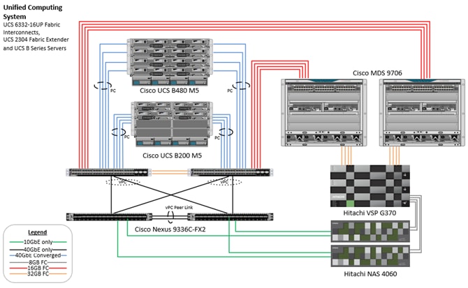
The components of this integrated architecture are:
· Cisco Nexus 9336C-FX2 – 100Gb capable, LAN connectivity to the Cisco UCS compute resources.
· Cisco UCS 6332-16UP Fabric Interconnect – Unified management of Cisco UCS compute, and the compute’s access to storage and networks.
· Cisco UCS B200 M5 – High powered, versatile blade server with two 2nd generation Intel® Xeon® Scalable processors.
· Cisco UCS B480 M5 – High powered, versatile blade server with four 2nd generation Intel® Xeon® Scalable processors.
· Cisco MDS 9706 – 16Gbps Fiber Channel connectivity within the architecture, as well as interfacing to resources present in an existing data center.
· Hitachi VSP G370 – Mid-range, high performance storage subsystem with optional all-flash configuration.
· Cisco UCS Manager – Management delivered through the Fabric Interconnect, provides stateless compute, and policy driven implementation of the servers managed by it.
Physical Cabling
This section explains the cabling examples used in the validated environment. To make connectivity clear in this example, the tables include both the local and remote port locations.
This document assumes that out-of-band management ports are plugged into an existing management infrastructure at the deployment site. The upstream network from the Nexus 9336C-FX2 switches is out of scope of this document, with only the assumption that these switches will connect to the upstream switch or switches with a virtual Port Channel (vPC).
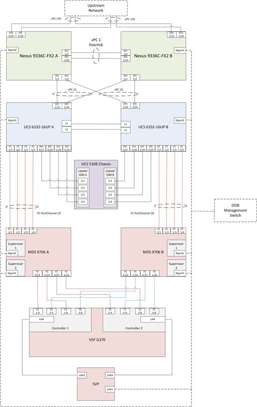
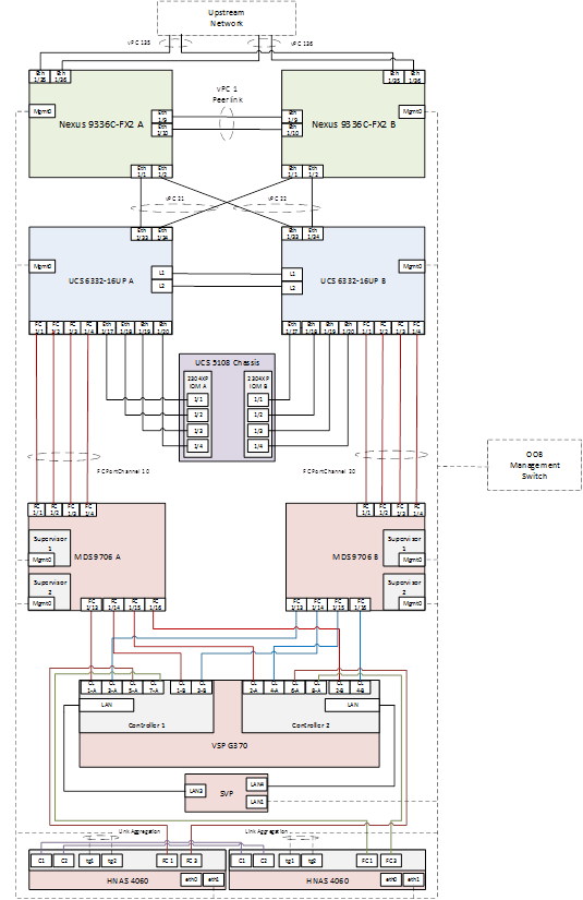
Table 1 through Table 6 provide the details of the specific port connections with the cables used in this deployment guide.
Table 1 Cisco Nexus 9336C-FX2 A Cabling Information
| Local Device |
Local Port |
Connection |
Remote Device |
Remote Port |
| Cisco Nexus 9336C-FX2 A
|
Eth1/1 |
40GbE |
Cisco UCS fabric interconnect A |
1/33 |
| Eth1/2 |
40GbE |
Cisco UCS fabric interconnect B |
1/33 |
|
| Eth1/9 |
40GbE |
Nx9336C-FX2-B |
1/9 |
|
| Eth1/10 |
40GbE |
Nx9336C-FX2-B |
1/10 |
|
| Eth1/31 |
40GbE |
Cisco UCS fabric interconnect A (optional) |
1/31 |
|
| Eth1/32 |
40GbE |
Cisco UCS fabric interconnect B (optional) |
1/31 |
|
| Eth1/11 |
10GbE |
HNAS Client Network Connection |
tg1 |
|
| Eth1/35 |
40GbE |
Customer Uplink Switch -A |
Any |
|
| Eth1/36 |
40GbE |
Customer Uplink Switch -B |
Any |
|
| MGMT0 |
GbE |
Customer Management Switch |
Any |
Table 2 Cisco Nexus 9336C-FX2 A Cabling Information
| Local Device |
Local Port |
Connection |
Remote Device |
Remote Port |
| Cisco Nexus 9336C-FX2 B
|
Eth1/1 |
40GbE |
Cisco UCS fabric interconnect A |
1/34 |
| Eth1/2 |
40GbE |
Cisco UCS fabric interconnect B |
1/34 |
|
| Eth1/9 |
40GbE |
Nx9336C-FX2-B |
1/9 |
|
| Eth1/10 |
40GbE |
Nx9336C-FX2-B |
1/10 |
|
| Eth1/31 |
40GbE |
Cisco UCS fabric interconnect A (optional) |
1/32 |
|
| Eth1/32 |
40GbE |
Cisco UCS fabric interconnect B (optional) |
1/32 |
|
| Eth1/12 |
10GbE |
HNAS Client Network Connection |
tg2 |
|
| Eth1/35 |
40GbE |
Customer Uplink Switch -A |
Any |
|
| Eth1/36 |
40GbE |
Customer Uplink Switch -B |
Any |
|
| MGMT0 |
GbE |
Customer Management Switch |
Any |
Table 3 Cisco UCS 6332-16UP A Cabling Information
| Local Device |
Local Port |
Connection |
Remote Device |
Remote Port |
| Cisco UCS 6332-16UP FI A
|
Eth1/1 |
FC uplink |
MDS-A |
1/1 |
| Eth1/2 |
FC uplink |
MDS-A |
1/2 |
|
| Eth1/3 |
FC uplink |
MDS-A |
1/3 |
|
| Eth1/4 |
FC uplink |
MDS-A |
1/4 |
|
| Eth1/17 |
40GbE |
Cisco UCS 5108 Chassis 1 – IOM A |
1/1 |
|
| Eth1/18 |
40GbE |
Cisco UCS 5108 Chassis 1 – IOM A |
1/2 |
|
| Eth1/19 |
40GbE |
Cisco UCS 5108 Chassis 1 – IOM A |
1/3 |
|
| Eth1/20 |
40GbE |
Cisco UCS 5108 Chassis 1 – IOM A |
1/4 |
|
| Eth1/21 |
40GbE |
Cisco UCS 5108 Chassis 1 – IOM A |
1/1 |
|
| Eth1/22 |
40GbE |
Cisco UCS 5108 Chassis 1 – IOM A |
1/2 |
|
| Eth1/23 |
40GbE |
Cisco UCS 5108 Chassis 1 – IOM A |
1/3 |
|
| Eth1/24 |
40GbE |
Cisco UCS 5108 Chassis 1 – IOM A |
1/4 |
|
| Eth1/31 |
40GbE |
Nx9336C-FX2-A (optional) |
1/31 |
|
| Eth1/32 |
40GbE |
Nx9336C-FX2-B (optional) |
1/31 |
|
| Eth1/33 |
40GbE |
Nx9336C-FX2-A |
1/1 |
|
| Eth1/34 |
40GbE |
Nx9336C-FX2-B |
1/1 |
|
| MGMT0 |
GbE |
Customer Management Switch |
Any |
|
| L1 |
GbE |
Cisco UCS fabric interconnect B |
L1 |
|
| L2 |
GbE |
Cisco UCS fabric interconnect B |
L2 |
Table 4 Cisco UCS 6332-16UP B Cabling Information
| Local Device |
Local Port |
Connection |
Remote Device |
Remote Port |
| Cisco UCS 6332-16UP FI B
|
Eth1/1 |
FC uplink |
MDS-B |
1/1 |
| Eth1/2 |
FC uplink |
MDS-B |
1/2 |
|
| Eth1/3 |
FC uplink |
MDS-B |
1/3 |
|
| Eth1/4 |
FC uplink |
MDS-B |
1/4 |
|
| Eth1/17 |
40GbE |
Cisco UCS 5108 Chassis 1 – IOM B |
1/1 |
|
| Eth1/18 |
40GbE |
Cisco UCS 5108 Chassis 1 – IOM B |
1/2 |
|
| Eth1/19 |
40GbE |
Cisco UCS 5108 Chassis 1 – IOM B |
1/3 |
|
| Eth1/20 |
40GbE |
Cisco UCS 5108 Chassis 1 – IOM B |
1/4 |
|
| Eth1/21 |
40GbE |
Cisco UCS 5108 Chassis 1 – IOM B |
1/1 |
|
| Eth1/22 |
40GbE |
Cisco UCS 5108 Chassis 1 – IOM B |
1/2 |
|
| Eth1/23 |
40GbE |
Cisco UCS 5108 Chassis 1 – IOM B |
1/3 |
|
| Eth1/24 |
40GbE |
Cisco UCS 5108 Chassis 1 – IOM B |
1/4 |
|
| Eth1/31 |
40GbE |
Nx9336C-FX2-A (optional) |
1/32 |
|
| Eth1/32 |
40GbE |
Nx9336C-FX2-B (optional) |
1/32 |
|
| Eth1/33 |
40GbE |
Nx9336C-FX2-A |
1/2 |
|
| Eth1/34 |
40GbE |
Nx9336C-FX2-B |
1/2 |
|
| MGMT0 |
GbE |
Customer Management Switch |
Any |
|
| L1 |
GbE |
Cisco UCS fabric interconnect B |
L1 |
|
| L2 |
GbE |
Cisco UCS fabric interconnect B |
L2 |
Table 5 Cisco MDS 9706 A Cabling Information
| Local Device |
Local Port |
Connection |
Remote Device |
Remote Port |
| Cisco MDS 9706 A
|
Eth1/1 |
FC uplink |
Cisco UCS fabric interconnect A |
1/1 |
| Eth1/2 |
FC uplink |
Cisco UCS fabric interconnect A |
1/2 |
|
| Eth1/3 |
FC uplink |
Cisco UCS fabric interconnect A |
1/3 |
|
| Eth1/4 |
FC uplink |
Cisco UCS fabric interconnect A |
1/4 |
|
| Eth1/13 |
FC uplink |
Hitachi VSP G370 – Controller 1 |
CL1-A |
|
| Eth1/14 |
FC uplink |
Hitachi VSP G370 – Controller 1 |
CL1-B |
|
| Eth1/15 |
FC uplink |
Hitachi VSP G370 – Controller 2 |
CL2-A |
|
| Eth1/16 |
FC uplink |
Hitachi VSP G370 – Controller 2 |
CL2-B |
|
| MGMT0 |
GbE |
Customer Management Switch |
Any |
Table 6 Cisco MDS 9706 B Cabling Information
| Local Device |
Local Port |
Connection |
Remote Device |
Remote Port |
| Cisco MDS 9706 B
|
Eth1/1 |
FC uplink |
Cisco UCS fabric interconnect B |
1/1 |
| Eth1/2 |
FC uplink |
Cisco UCS fabric interconnect B |
1/2 |
|
| Eth1/3 |
FC uplink |
Cisco UCS fabric interconnect B |
1/3 |
|
| Eth1/4 |
FC uplink |
Cisco UCS fabric interconnect B |
1/4 |
|
| Eth1/13 |
FC uplink |
Hitachi VSP G370 – Controller 1 |
CL3-A |
|
| Eth1/14 |
FC uplink |
Hitachi VSP G370 – Controller 1 |
CL3-B |
|
| Eth1/15 |
FC uplink |
Hitachi VSP G370 – Controller 2 |
CL4-A |
|
| Eth1/16 |
FC uplink |
Hitachi VSP G370 – Controller 2 |
CL4-B |
|
| MGMT0 |
GbE |
Customer Management Switch |
Any |
Hardware and Software Versions
Table 7 lists the validated hardware and software versions used for this reference architecture deployment. The deployment guide provides configuration specifics for the devices and software installation and the versions are listed in the following tables. Component and software version substitution from what is listed is considered acceptable within this reference architecture, but substitution will need to comply with the hardware and software compatibility matrices from Cisco, Hitachi and SAP, please refer to the documentation in Appendix B and below compatibility matrixes and release documentation:
· Cisco UCS Hardware and Software Compatibility Matrix: https://ucshcltool.cloudapps.cisco.com/public/
· Cisco Nexus and MDS Interoperability Matrix: https://www.cisco.com/c/en/us/td/docs/switches/datacenter/mds9000/interoperability/matrix/intmatrx/Matrix1.html
· Cisco Nexus Recommended Releases for Nexus 9K: https://www.cisco.com/c/en/us/td/docs/switches/datacenter/nexus9000/sw/recommended_release/b_Minimum_and_Recommended_Cisco_NX-OS_Releases_for_Cisco_Nexus_9000_Series_Switches.html
· Cisco MDS Recommended Releases: https://www.cisco.com/c/en/us/td/docs/switches/datacenter/mds9000/sw/b_MDS_NX-OS_Recommended_Releases.html
· Hitachi Vantara Interoperability Report: https://support.hitachivantara.com/en_us/interoperability.html
In addition, any substituted hardware or software may have different configurations from what is detailed in this guide and will require a thorough evaluation of the substituted product reference documents.
Table 7 Validated Hardware and Software
| Component |
Software/Firmware Version |
|
| Network |
Cisco Nexus 9336C-FX2 |
7.0(3)I7(5a) |
| Cisco MDS 9706 |
8.3(1) |
|
| Compute |
Cisco UCS Fabric Interconnect 6332 |
4.0(4b) |
| Cisco UCS 2304 IOM |
4.0(4b) |
|
| Cisco UCS B480 M5 Blade Server |
4.0(4b) |
|
| Cisco UCS B200 M5 Blade Server |
4.0(4b) |
|
| SUSE Linux Enterprise Server for SAP Applications |
SLES for SAP Applications 15 GA |
|
| Red Hat Enterprise Linux for SAP Solutions |
RHEL for SAP HANA 7.6 |
|
| Storage |
Hitachi VSP G370 |
88-02-03-60/00 |
| Hitachi NAS Platform 4060 |
13.5.5336.06 |
|
The information in the deployment guide leads through a complete configuration of a customer environment. In this process, various steps require the usage of customer-specific naming conventions, IP addresses, VLAN schemes as well as to record appropriate MAC addresses.
Some hardware like the Cisco UCS Fabric Interconnects or Cisco UCS B-Series blade servers are configured similarly. This document details steps for provisioning multiple Cisco UCS hosts which are identified sequentially, like:
HANA-Server0{1 | 2}.
In this document the angle brackets (<>) indicate a character string that the user needs to enter like a variable pertinent to the customer environment or a password in a given step.
Variables
Use the configuration variables summarized in Appendix A to document site specific variables and use them during the implementation of the configuration steps detailed in this deployment guide. Requirements
All physical hardware needs to be racked according to their specific hardware installation guides. This deployment guides assumes the cabling is complete and based on the physical cabling detailed in the Technology Overview chapter. All hardware is powered off prior of starting the initial configuration.
A Hitachi Virtual Storage Platform F/G series specialist must install the Hitachi Virtual Storage Platform G370. The Hitachi Distribution Center provides the initial Hitachi VSP configuration.
Scale
For SAP HANA deployments, there are two approaches to scale the environment: Scale-Up (single-node) and Scale-Out (multi-node). The term Scale-Up means the size of a single compute node will be increased when it comes to the amount of CPU sockets and physical amount of RAM. The term Scale-Out means to span a single system across multiple, independent servers.
A single Hitachi VSP F/G 350 or 370 can handle up to 16 Cisco UCS Servers in any Scale-Up or Scale-Out configuration. The converged infrastructure handles more SAP HANA nodes with different Hitachi VSP storage systems. While the Hitachi VSP G/F700 scales up to 34 Cisco UCS servers the Hitachi VSP G/F900 scales up to 40 Cisco UCS Servers in total per VSP. The Hitachi VSP E990 scales up to 50 nodes and the largest certified deployment handles 222 HANA nodes with 6 Hitachi VSP 5500/5500H series attached.
.
Cisco Nexus Switch Configuration
The following section provides a detailed procedure for configuring the Cisco Nexus 9000 Switches for SAP HANA environment. The Nexus switch configuration will explain the basic L2 and L3 functionality for the application environment used in the validation environment hosted by the UCS domains. The application gateways are hosted by the pair of Nexus switches, but primary routing is passed onto an existing router that is upstream of the converged infrastructure. This upstream router will need to be aware of any networks created on the Nexus switches, but configuration of an upstream router is beyond the scope of this deployment guide.
The switch configuration in this section based on cabling plan described in the Physical Cabling section. If the systems connected on different ports, configure the switches accordingly following the guidelines described in this section
![]() The configuration steps detailed in this section provides guidance to configure the Cisco Nexus 9000 running release 7.0(3)I7(5a) within a multi-VDC environment.
The configuration steps detailed in this section provides guidance to configure the Cisco Nexus 9000 running release 7.0(3)I7(5a) within a multi-VDC environment.
Initial Basic Configuration
Establish a serial connection to the console port of the switch, unless Power on Auto Provisioning is being used. To create the basic configuration, follow this dialogue on each switch.
Abort Power on Auto Provisioning and continue with normal setup? (yes/no) [n]: yes
---- System Admin Account Setup ----
Do you want to enforce secure password standard (yes/no) [y]:
Enter the password for "admin": <var_nexus_admin_pw>
Confirm the password for "admin": <var_nexus_admin_pw>
---- Basic System Configuration Dialog VDC: 1 ----
This setup utility will guide you through the basic configuration of
the system. Setup configures only enough connectivity for management
of the system.
Please register Cisco Nexus9000 Family devices promptly with your
supplier. Failure to register may affect response times for initial
service calls. Nexus9000 devices must be registered to receive
entitled support services.
Press Enter at any time to skip a dialog. Use ctrl-c at anytime
to skip the remaining dialogs.
Would you like to enter the basic configuration dialog (yes/no): yes
Create another login account (yes/no) [n]:
Configure read-only SNMP community string (yes/no) [n]:
Configure read-write SNMP community string (yes/no) [n]:
Enter the switch name : {<var_nexus_A_hostname> | <var_nexus_B_hostname>}
Continue with Out-of-band (mgmt0) management configuration? (yes/no) [y]:
Mgmt0 IPv4 address : {<var_nexus_A_mgmt_ip> | <var_nexus_B_mgmt_ip>}
Mgmt0 IPv4 netmask : <var_oob_mask>
Configure the default gateway? (yes/no) [y]:
IPv4 address of the default gateway : <var_oob_gateway>
Configure advanced IP options? (yes/no) [n]:
Enable the telnet service? (yes/no) [n]:
Enable the ssh service? (yes/no) [y]:
Type of ssh key you would like to generate (dsa/rsa) [rsa]:
Number of rsa key bits <1024-2048> [1024]:
Configure the ntp server? (yes/no) [n]: y
NTP server IPv4 address: <var_oob_ntp_ip>
Configure default interface layer (L3/L2) [L2]:
Configure default switchport interface state (shut/noshut) [noshut]: shut
Configure CoPP system profile (strict/moderate/lenient/dense) [strict]:
The following configuration will be applied:
password strength-check
switchname {<var_nexus_A_hostname> | <var_nexus_B_hostname>}
vrf context management
ip route 0.0.0.0/0 <var_oob_gateway>
exit
no feature telnet
ssh key rsa 1024 force
feature ssh
system default switchport
system default switchport shutdown
copp profile strict
interface mgmt0
ip address {<var_nexus_A_mgmt_ip> | <var_nexus_B_mgmt_ip>} <var_mgmt_mask>
no shutdown
Would you like to edit the configuration? (yes/no) [n]:
Use this configuration and save it? (yes/no) [y]:
Enable Cisco Nexus 9000 Series Switch Features and Settings
To enable the IP switching feature and set the default spanning tree behaviors on each Nexus 9000, follow these steps:
1. Enter the configuration mode:
config terminal
2. Enable the necessary features:
feature udld
feature lacp
feature vpc
feature interface-vlan
feature lldp
3. Configure spanning tree defaults:
spanning-tree port type network default
spanning-tree port type edge bpduguard default
spanning-tree port type edge bpdufilter default
4. Save the running configuration to start-up:
copy run start
Create VLANs for SAP HANA traffic
To create the necessary VLANs, follow these steps on each Nexus 9000 switch:
1. In configuration mode, run the following commands:
vlan <var_mgmt_vlan_id> name HANA-Node-Mgmt
vlan <var_backup_vlan_id> name HANA-Node-Backup
vlan <var_client_vlan_id> name HANA-Client
vlan <var_appserver_vlan_id> name HANA-AppServer
vlan <var_datasource_vlan_id> name HANA-DataSource
vlan <var_replication_vlan_id> name HANA-System-Replication
2. For SAP HANA Scale-Out deployments, add two additional VLANs:
vlan <var_internal_vlan_id> name HANA-Internal
vlan <var_nfsshared_vlan_id> name HANA-NFSshared
Configure Virtual Port-Channel Domain
Configure the Virtual Port-Channel (vPC) feature to configure a Port-Channel across the Nexus 9000 Switches.
Cisco Nexus 9000 A
To configure vPCs for switch A, follow these steps:
1. In configuration mode, create a new vPC domain:
vpc domain <var_nexus_vpc_domain_id>
2. Make Nexus 9000A the primary vPC peer by defining a low priority value:
role priority 10
3. Use the management interfaces on the supervisors of the Nexus 9000s to establish a keepalive link:
peer-keepalive destination <var_nexus_B_mgmt_ip> source <var_nexus_A_mgmt_ip>
4. Enable following features for this vPC domain:
peer-switch
delay restore 150
peer-gateway
auto-recovery
Cisco Nexus 9000 B
To configure vPCs for switch B, follow these steps:
1. In configuration mode, define the same vPC domain in switch B:
vpc domain <var_nexus_vpc_domain_id>
2. Make the Cisco Nexus 900 B the secondary vPC peer and define a higher priority value than for Nexus 9000 A:
role priority 20
3. Use the management interface on the supervisors of the Cisco Nexus 9000 switches to establish a keepalive link:
peer-keepalive destination <var_nexus_A_mgmt_ip> source <var_nexus_B_mgmt_ip>
4. Enable the following features for this vPC domain:
peer-switch
delay restore 150
peer-gateway
auto-recovery
Configure Network Interfaces for the VPC Peer Links
Cisco Nexus 9000 A
1. Define a port description for the interfaces connecting to VPC Peer <var_nexus_B_hostname>.
interface eth1/9 description VPC Peer <var_nexus_B_hostname>:1/9
interface eth1/10 description VPC Peer <var_nexus_B_hostname>:1/10
2. Apply a port channel to both VPC Peer links and bring up the interfaces:
interface eth1/9-10
channel-group 10 mode active
no shutdown
3. Define a description for the port-channel connecting to <var_nexus_B_hostname>:
interface Po10
description vPC peer-link
4. Make the port-channel a switchport, and configure a trunk to allow HANA VLANs:
switchport
switchport mode trunk
switchport trunk allowed vlan <var_mgmt_vlan_id>, <var_backup_vlan_id>, <var_client_vlan_id>, <var_appserver_vlan_id>, <var_datasource_vlan_id>, <var_replication_vlan_id>
5. For SAP HANA Scale-Out environment add the NFS shared and internal VLAN configuration:
switchport trunk allowed vlan <var_nfsshared_vlan_id>, <var_internal_vlan_id>
6. Make this port-channel the VPC peer link and bring it up:
spanning-tree port type network
vpc peer-link
no shutdown
Cisco Nexus 9000 B
1. Define a port description for the interfaces connecting to VPC Peer <var_nexus_A_hostname>.
interface eth1/9 description VPC Peer <var_nexus_A_hostname>:1/9
interface eth1/10 description VPC Peer <var_nexus_A_hostname>:1/10
2. Apply a port channel to both VPC Peer links and bring up the interfaces:
interface eth1/35-36
channel-group 10 mode active
no shutdown
3. Define a description for the port-channel connecting to <var_nexus_A_hostname>:
interface Po10
description vPC peer-link
4. Make the port-channel a switchport, and configure a trunk to allow HANA VLANs:
switchport
switchport mode trunk
switchport trunk allowed vlan <var_mgmt_vlan_id>, <var_backup_vlan_id>, <var_client_vlan_id>, <var_appserver_vlan_id>, <var_datasource_vlan_id>, <var_replication_vlan_id>
5. For SAP HANA Scale-Out environment add the NFS shared and internal VLAN configuration:
switchport trunk allowed vlan <var_nfsshared_vlan_id>, <var_internal_vlan_id>
6. Make this port-channel the VPC peer link and bring it up:
spanning-tree port type network
vpc peer-link
no shutdown
Configure vPCs with Cisco Fabric Interconnect
To configure the vPCs for the usage by the Client, Admin and internal zone network traffic, follow these steps on each Cisco Nexus 9000 switch separately:
1. Define a port description for the interfaces connecting to <var_ucs_clustername>-A:
interface eth1/1
description <var_ucs_clustername>-A:1/33
![]() While running this on Switch B, please note the change in remote port in the description command. In the current example, it would be “description <var_ucs_clustername>-A:1/33” based on the connectivity details. The same can be verified from command show cdp neighbours.
While running this on Switch B, please note the change in remote port in the description command. In the current example, it would be “description <var_ucs_clustername>-A:1/33” based on the connectivity details. The same can be verified from command show cdp neighbours.
2. Apply it to a port channel and bring up the interface:
interface eth1/1
channel-group 21 mode active
no shutdown
3. Define a description for the port-channel connecting to <var_ucs_clustername>-A:
interface Po21
description <var_ucs_clustername>-A
4. Make the port-channel a switchport and configure a trunk to allow all HANA VLANs:
switchport
switchport mode trunk
switchport trunk allowed vlan <var_mgmt_vlan_id>, <var_client_vlan_id>, <var_appserver_vlan_id>, <var_datasource_vlan_id>, <var_replication_vlan_id>
5. For SAP HANA Scale-Out environment add the NFS Shared and Internal VLAN configuration:
switchport trunk allowed vlan <var_nfsshared_vlan_id>, <var_internal_vlan_id>
6. Make the port channel and associated interfaces spanning tree edge ports:
spanning-tree port type edge trunk
7. Set the MTU to be 9216 to support jumbo frames:
mtu 9216
8. Make this a VPC port-channel and bring it up:
vpc 21
no shutdown
9. Define a port description for the interface connecting to <var_ucs_clustername>-B:
interface eth1/2
description <var_ucs_clustername>-B:1/33
![]() While running this on Switch B, please note the change in remote port in the description command. In the current example, it would be “description <var_ucs_clustername>-A:1/34” based on the connectivity details. The same can be verified from command show cdp neighbours.
While running this on Switch B, please note the change in remote port in the description command. In the current example, it would be “description <var_ucs_clustername>-A:1/34” based on the connectivity details. The same can be verified from command show cdp neighbours.
10. Apply it to a port channel and bring up the interface:
interface eth1/2
channel-group 22 mode active
no shutdown
11. Define a description for the port-channel connecting to <var_ucs_clustername>-B:
interface port-channel22
description <var_ucs_clustername>-B
12. Make the port-channel a switchport and configure a trunk to allow all HANA VLANs:
switchport
switchport mode trunk
switchport trunk allowed vlan <var_mgmt_vlan_id>, <var_client_vlan_id>, <var_appserver_vlan_id>, <var_datasource_vlan_id>, <var_replication_vlan_id>
13. For SAP HANA Scale-Out environment add the NFS Shared and Internal VLAN configuration:
switchport trunk allowed vlan <var_nfsshared_vlan_id>, <var_internal_vlan_id>
14. Make the port channel and associated interfaces spanning tree edge ports:
spanning-tree port type edge trunk
15. Set the MTU to be 9216 to support jumbo frames:
mtu 9216
16. Make this a VPC port-channel and bring it up:
vpc 22
no shutdown
(Optional) Configure SAP HANA Backup Networks to Use Separate vPCs
Optionally, configure additional vPCs for exclusive use by the Backup Network. The following example configures two ports Ethernet 1/31 and Ethernet1/32 connected to Eth1/31 and Eth1/32 on the UCS Fabric Interconnects.
Cisco Nexus 9000 A and Cisco Nexus 9000 B
1. Define a port description for the interface connecting to <var_node01>.
interface eth1/31
description <var_ucs_clustername>-A:1/31
![]() While running this on Switch B, please note the change in remote port in the description command. In the current example, it would be “description <var_ucs_clustername>-A:1/31” based on the connectivity details. The same can be verified from command show cdp neighbours.
While running this on Switch B, please note the change in remote port in the description command. In the current example, it would be “description <var_ucs_clustername>-A:1/31” based on the connectivity details. The same can be verified from command show cdp neighbours.
2. Apply it to a port channel and bring up the interface.
interface eth1/31
channel-group 31 mode active
no shutdown
3. Define a description for the port-channel connecting to <var_backup_node01>.
interface Po31
description PC-from-FI-A
4. Make the port-channel a switchport and configure a trunk to allow NFS VLAN for DATA.
switchport
switchport mode trunk
switchport trunk allowed vlan <var_backup_vlan_id>
5. Make the port channel and associated interfaces spanning tree edge ports.
spanning-tree port type edge trunk
6. Set the MTU to be 9216 to support jumbo frames.
mtu 9216
7. Make this a VPC port-channel and bring it up.
vpc 31
no shutdown
8. Define a port description for the interface connecting to <var_node02>.
interface eth1/32
description <var_ucs_clustername>-B:1/31
![]() While running this on Switch B, please note the change in remote port in the description command. In the current example, it would be “description <var_ucs_clustername>-B:1/31” based on the connectivity details. The same can be verified with the command show cdp neighbours.
While running this on Switch B, please note the change in remote port in the description command. In the current example, it would be “description <var_ucs_clustername>-B:1/31” based on the connectivity details. The same can be verified with the command show cdp neighbours.
9. Apply it to a port channel and bring up the interface.
channel-group 32 mode active
no shutdown
10. Define a description for the port-channel connecting to <var_node02>.
interface Po32
description PC-from-FI-B
11. Make the port-channel a switchport, and configure a trunk to allow NFS VLAN for DATA.
switchport
switchport mode trunk
switchport trunk allowed vlan <var_backup_vlan_id>
12. Make the port channel and associated interfaces spanning tree edge ports.
spanning-tree port type edge trunk
13. Set the MTU to be 9216 to support jumbo frames.
mtu 9216
14. Make this a VPC port-channel and bring it up.
vpc 32
no shutdown
![]() Ensure to save the configuration to the startup config using the command copy running-config startup-config.
Ensure to save the configuration to the startup config using the command copy running-config startup-config.
Set Global NTP Configurations
The NTP server should be accessible by both Nexus switches. In this case, point to an out-of-band source. To set global NTP configurations, follow these steps:
1. Run the following commands on both switches to set global configurations:
configure terminal
feature ntp
ntp server <var_oob_ntp_ip> use-vrf management
ntp master 3
ntp source <var_nexus_ib_vip>
2. Save the running configuration to start-up on both Nexus switches:
copy run start
![]() Setting the switches as NTP masters to redistribute as NTP source is optional here but can be a valuable fix, if the tenant networks are not enabled to reach the primary NTP server.
Setting the switches as NTP masters to redistribute as NTP source is optional here but can be a valuable fix, if the tenant networks are not enabled to reach the primary NTP server.
Hitachi Storage Configuration
A Hitachi Virtual Storage Platform F/G series specialist must install Hitachi Virtual Storage Platform G370. The initial configuration for VSP G370 is done in the Hitachi Distribution Centers.
If IP addresses of the SVP are not known at build time in the distribution center, they will be set to a default value and need change onsite by the Hitachi storage specialist.
Storage Architecture Overview
Each SAP HANA node needs the following storage layout:
· Operating system (OS) volume
· SAP HANA shared volume
· SAP HANA log volume
· SAP HANA data volume
On an SAP HANA Scale Out System each node will have a central mount from an NFS Export provided by the HNAS for the SAP HANA binaries instead of a mapped SAP HANA shared volume from a VSP Storage which be used in SAP HANA Scale Up environment.
This SAP HANA TDI setup utilizes the following two dynamic provisioning pools created with Hitachi Dynamic Provisioning for the storage layout. This ensures maximum utilization and optimization at a lower cost than other solutions.
· OS_SH_DT_Pool for the following:
- OS volume
- SAP HANA shared volume
- SAP HANA data volume
· LOG_Pool for the following:
- SAP HANA log volume
The validated dynamic provisioning pool layout options with minimal disks and storage cache on Hitachi Virtual Storage Platform F350, VSP G350, F370, VSP G370, VSP F700, VSP G700, VSP F900, VSP G900 Series and VSP 5000 Series storage is listed in Table 8 .
Table 8 Dynamic Provisioning Pools with Disks and Storage Cache
| Storage |
Cache |
Nodes Number |
Number of Parity Groups in OS_SH_DT_Pool |
Number of Parity Groups in LOG_Pool |
| RAID-10 (2D+2D) |
RAID-10 (2D+2D) |
|||
| VSP F350, VSP G350, VSP F370, VSP G370 (with SSD) |
VSP F350, VSP G350: 128 GB VSP F370, VSP G370: 256GB |
up to 8 |
1 |
1 |
| up to 15 |
2 |
2 |
||
| up to 16 |
3 |
3 |
||
| VSP F700, VSP G700 (with SSD) |
512 GB |
up to 11 |
1 |
1 |
| up to 20 |
2 |
2 |
||
| up to 28 |
3 |
3 |
||
| up to 30 |
4 |
4 |
||
| up to 32 |
4 |
5 |
||
| VSP F900, VSP G900 (with SSD) |
1024GB |
up to 17 |
1 |
1 |
| up to 23 |
2 |
2 |
||
| up to 31 |
3 |
3 |
||
| up to 32 |
4 |
3 |
||
| VSP 5100, VSP 5100H |
1024GB |
up to 37 |
3 |
1 |
| VSP 5500, VSP 5500H (1 pair of nodes) |
2048GB |
up to 74 |
14 |
14 |
| VSP5500, VSP5500H (2 pair of nodes) |
3072GB |
up to 148 |
28 |
28 |
| VSP5500, VSP5500H (3 pair of nodes) |
6144GB |
up to 222 |
42 |
42 |
Additional parity groups of the same type may need to be added. Drive boxes may be required if the internal number of disk drives on the storage are not enough, depending on:
· The various combinations of node sizes
· The number of nodes to meet the capacity requirements
While it is not limited to these systems, this SAP HANA tailored data center integration solution uses the following four active SAP HANA systems, as examples:
· System 1 — 384 GB
· System 2 — 768 GB
· System 3 — 1536 GB
· System 4 — 3072 GB
Provision the storage for the four SAP HANA systems listed above:
· Determine the minimum sizes for operating system, data, log, and HANA shared using these formulas in SAP white pager SAP HANA Storage Requirements as following:
- Every HANA node requires approximately 100 GB capacity for the operating system.
- /hana/shared size uses formulas:
§ Single node (scale-up) — Size = MIN (1 × RAM; 1 TB)
§ Multi-node (scale-out) — Size = 1 × RAM of every 4 worker nodes
- Data size requires at least 1.2 × RAM (DRAM + Intel Optane DCPMM) of each HANA node
- Log size uses formulas:
§ Systems with equal or less than 512 GB memory — Size = 1/2 × RAM
§ Systems with greater than 512 GB memory — Size = 512 GB
· Provision the storage:
- Create two dynamic provisioning pools for the three SAP HANA systems on storage:
§ Use OS_SH_DT_Pool to provision the operating system volume, SAP HANA shared volume, and Data volume.
§ Use LOG_Pool to provision the Log volume.
- For SSDs, create the parity groups first, as the example listed in Table 9 for Hitachi Virtual Storage Platform G370, using the RAID-10 storage design.
Table 9 Dynamic Provisioning Pool with RAID10(2D+2D) for 16 Nodes on VSP F370 and G370 with SSDs
| Dynamic Provisioning Pool |
Parity Group ID |
Parity Group RAID Level and Disks |
LDEV ID |
LDEV Name |
LDEV Size |
MPU Assignment |
| OS_SH_DT_Pool |
1 |
RAID-10 (2D+2D) on 1.9 TB SSD |
00:00:01 |
OS_SH_DT_DPVOL_1 |
878 GB |
MPU-10 |
| 00:00:02 |
OS_SH_DT_DPVOL_2 |
878 GB |
MPU-20 |
|||
| 00:00:03 |
OS_SH_DT_DPVOL_3 |
878 GB |
MPU-10 |
|||
| 00:00:04 |
OS_SH_DT_DPVOL_4 |
878 GB |
MPU-20 |
|||
| 2 |
RAID-10 (2D+2D) on 1.9 TB SSD |
00:00:05 |
OS_SH_DT_DPVOL_5 |
878 GB |
MPU-10 |
|
| 00:00:06 |
OS_SH_DT_DPVOL_6 |
878 GB |
MPU-20 |
|||
| 00:00:07 |
OS_SH_DT_DPVOL_7 |
878 GB |
MPU-10 |
|||
| 00:00:08 |
OS_SH_DT_DPVOL_8 |
878 GB |
MPU-20 |
|||
| 3 |
RAID-10 (2D+2D) on 1.9 TB SSD |
00:00:09 |
OS_SH_DT_DPVOL_9 |
878 GB |
MPU-10 |
|
| 00:00:10 |
OS_SH_DT_DPVOL_10 |
878 GB |
MPU-20 |
|||
| 00:00:11 |
OS_SH_DT_DPVOL_11 |
878 GB |
MPU-10 |
|||
| 00:00:12 |
OS_SH_DT_DPVOL_12 |
878 GB |
MPU-20 |
|||
| LOG_Pool |
4 |
RAID-10 (2D+2D) on 1.9 TB SSD |
00:00:13 |
LG_DPVOL_1 |
878 GB |
MPU-10 |
| 00:00:14 |
LG_DPVOL_2 |
878 GB |
MPU-20 |
|||
| 00:00:15 |
LG_DPVOL_3 |
878 GB |
MPU-10 |
|||
| 00:00:16 |
LG_DPVOL_4 |
878 GB |
MPU-20 |
|||
| 5 |
RAID-10 (2D+2D) on 1.9 TB SSD |
00:00:17 |
LG_DPVOL_5 |
878 GB |
MPU-10 |
|
| 00:00:18 |
LG_DPVOL_6 |
878 GB |
MPU-20 |
|||
| 00:00:19 |
LG_DPVOL_7 |
878 GB |
MPU-10 |
|||
| 00:00:20 |
LG_DPVOL_8 |
878 GB |
MPU-20 |
|||
| 6 |
RAID-10 (2D+2D) on 1.9 TB SSD |
00:00:21 |
LG_DPVOL_9 |
878 GB |
MPU-10 |
|
| 00:00:22 |
LG_DPVOL_10 |
878 GB |
MPU-20 |
|||
| 00:00:23 |
LG_DPVOL_11 |
878 GB |
MPU-10 |
|||
| 00:00:24 |
LG_DPVOL_12 |
878 GB |
MPU-20 |
· Assign all LDEVs to the dedicated pool for VSP G370.
· Create virtual volumes (VVOLs) for the operating system, SAP HANA shared, log, and data volumes. Table 10 lists examples for HANA systems with memory of 384 GB, 768 GB, 1536 GB, and 3072 GB.
Table 10 VVOLs for SAP HANA Nodes for Four Memory Sizes of HANA Systems
| Dynamic Provisioning Pool |
VVOL ID |
VVOL Name |
VVOL Size |
MPU Assignment |
System Memory |
| OS_SH_DT_Pool |
00:01:00 |
HANA_OS_N1 |
100 GB |
MPU-10 |
384 GB |
| 00:02:00 |
HANA_OS_N2 |
100 GB |
MPU-20 |
768 GB |
|
| 00:03:00 |
HANA_OS_N3 |
100 GB |
MPU-10 |
1536 GB |
|
| 00:04:00 |
HANA_OS_N4 |
100 GB |
MPU-20 |
3072 GB |
|
| 00:01:01 |
HANA_SH_N1 |
384 GB |
MPU-10 |
384 GB |
|
| 00:02:01 |
HANA_SH_N2 |
768 GB |
MPU-20 |
768 GB |
|
| 00:03:01 |
HANA_SH_N3 |
1536 GB |
MPU-10 |
1536 GB |
|
| 00:04:01 |
HANA_SH_N4 |
3072 GB |
MPU-20 |
3072 GB |
|
| 00:01:06 |
HANA_DATA_N1_1 |
96 GB |
MPU-10 |
384 GB |
|
| 00:01:07 |
HANA_DATA_N1_2 |
96 GB |
MPU-20 |
||
| 00:01:08 |
HANA_DATA_N1_3 |
96 GB |
MPU-10 |
||
| 00:01:09 |
HANA_DATA_N1_4 |
96 GB |
MPU-20 |
||
| 00:02:06 |
HANA_DATA_N2_1 |
192 GB |
MPU-10 |
768 GB |
|
| 00:02:07 |
HANA_DATA_N2_2 |
192 GB |
MPU-20 |
||
| 00:02:08 |
HANA_DATA_N2_3 |
192 GB |
MPU-10 |
||
| 00:02:09 |
HANA_DATA_N2_4 |
192 GB |
MPU-20 |
||
| 00:03:06 |
HANA_DATA_N3_1 |
384 GB |
MPU-10 |
1536 GB |
|
| 00:03:07 |
HANA_DATA_N3_2 |
384 GB |
MPU-20 |
||
| 00:03:08 |
HANA_DATA_N3_3 |
384 GB |
MPU-10 |
||
| 00:03:09 |
HANA_DATA_N3_4 |
384 GB |
MPU-20 |
||
| 00:04:06 |
HANA_DATA_N4_1 |
768 GB |
MPU-10 |
3072 GB |
|
| 00:04:07 |
HANA_DATA_N4_2 |
768 GB |
MPU-20 |
||
| 00:04:08 |
HANA_DATA_N4_3 |
768 GB |
MPU-10 |
||
| 00:04:09 |
HANA_DATA_N4_4 |
768 GB |
MPU-20 |
||
| LOG_Pool |
00:01:02 |
HANA_LOG_N1_1 |
48 GB |
MPU-10 |
384 GB |
| 00:01:03 |
HANA_LOG_N1_2 |
48 GB |
MPU-20 |
||
| 00:01:04 |
HANA_LOG_N1_3 |
48 GB |
MPU-10 |
||
| 00:01:05 |
HANA_LOG_N1_4 |
48 GB |
MPU-20 |
||
| 00:02:02 |
HANA_LOG_N2_1 |
96 GB |
MPU-10 |
768 GB |
|
| 00:02:03 |
HANA_LOG_N2_2 |
96 GB |
MPU-20 |
||
| 00:02:04 |
HANA_LOG_N2_3 |
96 GB |
MPU-10 |
||
| 00:02:05 |
HANA_LOG_N2_4 |
96 GB |
MPU-20 |
||
| 00:03:02 |
HANA_LOG_N3_1 |
128 GB |
MPU-10 |
1536 GB |
|
| 00:03:03 |
HANA_LOG_N3_2 |
128 GB |
MPU-20 |
||
| 00:03:04 |
HANA_LOG_N3_3 |
128 GB |
MPU-10 |
||
| 00:03:05 |
HANA_LOG_N3_4 |
128 GB |
MPU-20 |
||
| 00:04:02 |
HANA_LOG_N4_1 |
128 GB |
MPU-10 |
3072 GB |
|
| 00:04:03 |
HANA_LOG_N4_2 |
128 GB |
MPU-20 |
||
| 00:04:04 |
HANA_LOG_N4_3 |
128 GB |
MPU-10 |
||
| 00:04:05 |
HANA_LOG_N4_4 |
128 GB |
MPU-20 |
While mapping the LUN path assignment for each node, add VVOLs in the following order:
1. The operating system volume
2. The SAP HANA shared volume (for SAP HANA Scale-Up only)
3. The log volume
4. The data volume
Below table lists an example configuration of the LUN path assignment for Node 1. Configure the LUN assignment similarly for all other nodes.
Table 11 Example LUN Path Assignment for the SAP HANA Configuration on Node 1
| LDEV ID |
LDEV Name |
|
| 0000 |
00:01:00 |
HANA_OS_N1 |
| 0001 |
00:01:01 |
HANA_SH_N1 |
| 0002 |
00:01:02 |
HANA_LOG_N1_1 |
| 0003 |
00:01:03 |
HANA_LOG_N1_2 |
| 0004 |
00:01:04 |
HANA_LOG_N1_3 |
| 0005 |
00:01:05 |
HANA_LOG_N1_4 |
| 0006 |
00:01:06 |
HANA_DATA_N1_1 |
| 0007 |
00:01:07 |
HANA_DATA_N1_2 |
| 0008 |
00:01:08 |
HANA_DATA_N1_3 |
| 0009 |
00:01:09 |
HANA_DATA_N1_4 |
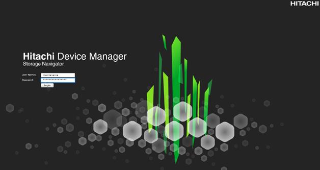
Log into Storage Navigator
After installing the VSP G370 onsite and running all necessary cable connections and powering up the VSP G370, open Hitachi Storage Navigator to start the configuration:
1. Access Hitachi Storage Navigator through a web browser.
2. https://<var_hitachi_svp_ip>/dev/storage/886000<Serial Number of Storage System>/emergency.do – for example, if Storage System SVP IP address is 192.168.50.21 and Serial Number of Storage System is 456789, the URL would be:
https://192.168.50.21/dev/storage/836000456789/emergency.do
3. Log into Hitachi Storage Navigator.
Check SFP Data Transfer Rate
When you first log in prior to starting the configuration of the storage, navigate to Port Condition to check the SFP Data Transfer Rate.
To check the SFP data transfer rate, follow these steps:
1. In the Storage Navigator window click Actions, Components and then View Port Condition.
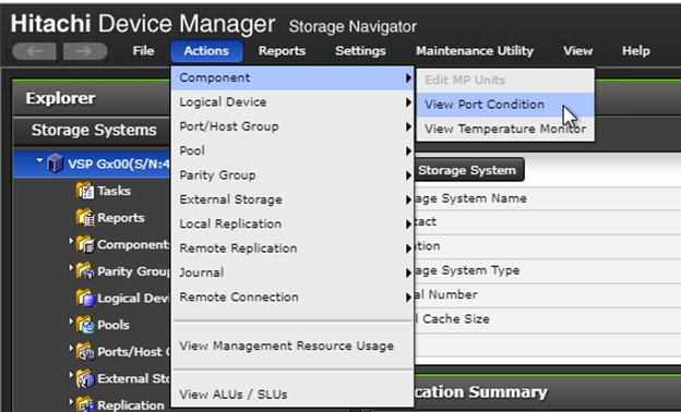
2. The port condition window opens. Make sure the transfer rate in the SFP Data Transfer Rate matches the speed of the SFPs in the storage controller. The actual Speed can differ, depending on the configuration of the other components.
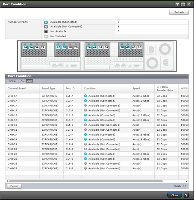
3. Click Close to close the Port Condition window and start with the storage configuration.
Create Pool Volumes
This procedure creates the Parity Groups and LDEVs using Hitachi Storage Navigator for the following:
· Operating System LUNs
· SAP HANA Shared LUNs
· SAP HANA Log LUNs
· SAP HANA Data LUNs
Use the storage navigator session from the previous section. Repeat these steps to create all the required pool volumes.
To create a pool volume, follow these steps:
1. Open the LDEV creation window.
2. In the General Tasks pane, click Create LDEVs. The 1 Create LDEVs dialog box opens.
3. Create Pool Volume LUN:
4. Create an LDEV.
a. Enter the values listed in Table 12 into the Create LDEVs dialog box.
Table 12 Pool Volume Creation for LOG_Pool and OS_SH_DT_Pool
| For This |
Enter This |
| Provisioning Type |
Click Basic |
| Drive Type/RPM |
Click SSD |
| RAID Level |
Click 1 (2D+2P) |
| Select Free Spaces |
Click the option |
| Parity Group |
Select the 1 (2D+2P) Parity Group |
| LDEV Capacity |
Type value 878 GB |
| Number of LDEVs per Free Space |
Type 4 for each RAID group |
| LDEV Name area |
Type the pool name as prefix and the next free number as int number, i.e. 1 for the first RAID group, 5 for the second etc. |
| Options area |
In the LDKC:CU:DEV text box, type the initial as listed in the LDEV ID column in Table 11 . |
| In the MPU assignment text box, select Auto |
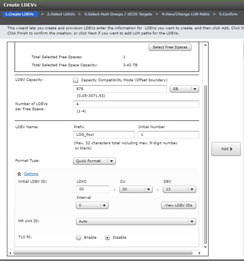
b. Click Add and then click Finish.
c. Acknowledge the Warning by clicking OK.
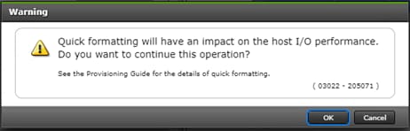
The Confirm window opens.
d. Confirm the selection again, and then click Apply.
e. Record the task name for later reference.
5. Repeat steps 1 to 4 to create every pool volume required by this installation.
6. Keep the Storage Navigator session open to create dynamic provisioning pools.
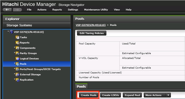
Create Dynamic Provisioning Pools
In the Storage Navigator session perform this procedure to create dynamic provisioning pools. This solution uses two dynamic provisioning pools:
· LOG_Pool
· OS_SH_DT_Pool
Follow the steps in this section to create the LOG_Pool and repeat these steps to create the OS_SH_DT_Pool.
To create a dynamic provisioning pool, follow these steps:
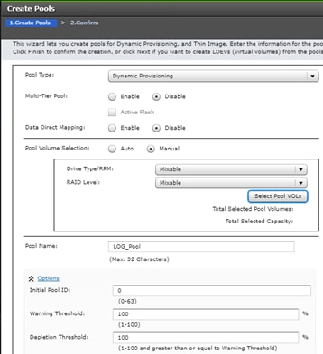
1. From Pools, click Create Pools to open the 1. Create Pools window.
2. Enter the values listed in Table 13 in the Create Pools dialog box.
Table 13 Dynamic Provisioning Pool Creation: LOG_Pool and OS_SH_DT_Pool
| For this: |
Enter this: |
| Pool Type |
Select Dynamic Provisioning |
| Multi-Tier Pool |
Disabled |
| Data Direct Mapping |
Disabled |
| Pool Volume Selection |
Click Manual |
| Pool Name |
LOG_Pool or OS_SH_DT_Pool |
| Initial Pool ID |
Type 0 for LOG_Pool or type 1 for OS_SH_DT_Pool |
| Warning Threshold |
100 |
| Deletion Threshold |
100 |
3. Select the pool volumes for the pool.
4. Click Select Pool VOLs.
5. Select the volumes.
6. For LOG_Pool, identify the pool volumes for the pool and select them. Click Add.
7. For OS_SH_DT_Pool, identify the pool volumes for the pool and select them. Click Add.
8. Click OK.
9. Click Add.
10. Click Finish on the 2. Confirm window.
11. Click Apply.
Provision the LUNS (Virtual Volumes)
![]() Follow the storage configuration outlined below for this solution. Do not make any changes to these instructions in the Distribution Center. SAP does not support any changes made to this exact configuration.
Follow the storage configuration outlined below for this solution. Do not make any changes to these instructions in the Distribution Center. SAP does not support any changes made to this exact configuration.
This procedure creates the LDEVs using Hitachi Storage Navigator for the following:
· Operating system LUNS
· SAP HANA shared LUNS
· Log LUNs
· Data LUNs
Assign each of the LUNs to specific MPU for optimal performance, map to LUN paths using specific LUN ID in sequence as listed Table 14 .
Create Virtual Volumes for the Operating System LUNS and Map Ports
Use Hitachi Storage Navigator to create the operating system LDEV and map it to specified Hitachi Virtual Storage Platform Fx00 or Gx00 ports.
To create LDEVs for the operating system boot LUN, follow these steps:
1. From Pools, click OS_SH_DT_Pool.
2. In the Virtual Volumes pane, click Create LDEVs. The 1 Create LDEVs dialog box opens.
3. Create operating system boot LUNS.
4. Create one operating system LUN per HANA node and assign it to the ports following Table 11 . Repeat this step until all operating LUNS are completed.
5. Create an LDEV.
a. Enter the values shown in Table 14 in the Create LDEVs dialog box.
Table 14 LDEV Creation Values for Operating System LUN
| For this: |
Enter this: |
| Provisioning Type |
Click Dynamic Provisioning |
| Drive Type/RPM |
Click SSD/- |
| RAID Level |
Click 1 (2D+2P) |
| Select Pool |
OS_SH_DT_Pool |
| LDEV Capacity |
Type 100 GB |
| Number of LDEVs per Free Space |
Type the node number to be added to the name. |
| LDEV Name area |
Type the Prefix for the LUN name: HANA_OS_N |
| Type the node number to be added to the name. |
|
| Full Allocation |
Enabled |
| Options area |
Type or click the values for LDKC, CU and DEV according to the VVOL ID column of table 12. |
| Select the value Auto for the MPU Unit ID. |
b. Click Add and then click Next.
6. The Select LDEV window displays all configured LDEVs in the right pane:
a. Select the host ports.
b. Click Next on the 2 Select LDEVs window. The 3 Select Host Groups/iSCSI Targets window opens.
c. From the Available Host Groups pane, select the OS LUN ports by referring to Table 13 .
d. Click Add.
e. The selected ports that were in the Available Hosts Groups pane are now in the Selected Host Groups pane.
f. Click Next.
7. The View/Change LUN Paths window displays.
8. Confirm the selected ports.
![]() The operating system LUN always has a LUN ID of 000.
The operating system LUN always has a LUN ID of 000.
9. Confirm the selected ports and adjust the LUN ID as listed in Table 13 .
10. Click Finish.
11. The Confirm window opens.
12. Confirm the selection again and then click Apply.
Record the task name for later reference.
Create Virtual Volumes for HANA Shared File System and Map Ports
In the Hitachi Storage Navigator create the HANA shared virtual volumes under dynamic provisioning pool OS_SH_DT_Pool and map them to specified storage ports.
The HANA Shared File System is provided by the HNAS as an NFS Export for the SAP HANA binaries in Scale-Out environments.
Repeat this procedure until all virtual volumes have been created.
To create a virtual volume for the HANA-shared file system and map ports, follow these steps:
1. From Pools, click OS_SH_DT_Pool.
2. Enter the values shown in Table 15 in the Create LDEVs dialog box.
Table 15 Virtual Volume Creation for HANA Shared LUNs
| For this: |
Enter this: |
| Provisioning Type |
Click Dynamic Provisioning |
| Drive Type/RPM |
Leave at SSD/- |
| RAID Level |
Leave at 1 (2D+2P) |
| Select Pool |
OS_SH_DT_Pool |
| LDEV Capacity |
Type the required volume size for /hana/shared volume in GB. This is equal or greater the memory size of the HANA node. |
| Number of LDEVs |
Type 1 |
| Full Allocation |
Click Enabled |
| LDEV Name area |
For LDEV Name Prefix, type the HANA Shared LUN LDEV name: HANA_SH_N |
| Type the node number to be added to the name. |
|
| Options area |
Type or click the values for LDK:CU:DEV according to the VVOL ID column of table 12.Table 1 |
| Click Auto for MP Unit ID of the MPU assignment. |
3. Click Add.
4. Click Finish on the 2. Confirm window.
5. Click Apply.
Create Virtual Volumes for Log LUNs and Map Ports
This procedure creates and maps LDEVs to the specified storage ports for the log LUNs.
To provision the LDEVs for log LUNs, follow the steps from the previous section with the following changes:
1. In the Hitachi Storage Navigator, go to Pools, click LOG_Pool.
2. Enter the values shown in Table 16 in the Create LDEVs dialog box.
Table 16 LDEV Creation Values for Log LUN
| For this: |
Enter this: |
| Provisioning Type |
Click Dynamic Provisioning |
| Drive Type/RPM |
Click SSD/- |
| RAID Level |
Click 1 (2D+2P) |
| Select Pool |
LOG_Pool |
| LDEV Capacity |
Type the required volume size divided by 4 in GB. For example, if a 512 GB log volume is needed, type 128 GB |
| Number of LDEVs per Free Space |
Type 4 |
| Full Allocation |
Click Enabled |
| LDEV Name area |
For LDEV Name Prefix, type the HANA Log LDEV name for this node: For example: HANA_LOG_N1_ |
| For Initial Number, type the HANA Log LDEV. |
|
| Options area |
Type or click the values for LDKC, CU and DEV in LDKC:CU:DEV according to the VVOL ID column of table 12 |
| Click the value for the MPU Unit ID. |
3. Click Add.
4. Click Finish on the second Confirm window.
5. Click Apply.
Keep the Storage Navigator session open for Create Virtual Volumes for Data LUNs and Map Ports.
Create Virtual Volumes for Data LUNs and Map Ports
This procedure creates and maps LDEVs to the specified Hitachi Virtual Storage Platform F370/G370 ports for the Data LUNs. Use the previously-opened Hitachi Storage Navigator session.
To provision the LDEVs for Data LUNs, follow the steps of the previous sections.
To create virtual volumes for data LUNs and map ports, follow these steps:
1. From Pools, click OS_SH_DT_Pool.
2. Enter the values shown in Table 9 in the Create LDEVs dialog box.
Table 17 LDEV Creation Values for Data LUN
| For this: |
Enter this: |
| Provisioning Type |
Click Dynamic Provisioning |
| Drive Type/RPM |
Click SSD/- |
| RAID Level |
Click 1 (2D+2P) |
| Select Pool |
OS_SH_DT_Pool |
| LDEV Capacity |
Type the required volume size divided by 4 in GB. For example, if a 4096 GB data volume is needed, type 1024 GB. |
| Number of LDEVs per Free Space |
Type 4 |
| Full Allocation |
Enabled |
| LDEV Name area |
For LDEV Name Prefix, type the HANA Data LDEV name: HANA_DT_VVOL_N |
| For Initial Number, type the HANA node number. |
|
| Options area |
Type or click the values for LDKC, CU and DEV in LDKC:CU:DEV according to the VVOL ID column of table 12. |
| Click the value for the MPU Unit ID. |
3. Click Add.
4. Click Finish on the 2. Confirm window
5. Click Apply.
Keep the Storage Navigator session open for the Configure the Host Groups procedure.
Storage Port Configuration
The following table lists the configuration and port mapping for Hitachi VSP Fx00 and Gx00 models and VSP 5000 Series.
Table 18 Storage Port Mapping for Validated SAP HANA Nodes using SSDs
| HBA Port |
Fiber Channel Switch Port Name |
Virtual Storage Platform Target Port-Host Group |
||||||||
| Port Name |
Port Speed |
Host |
Storage |
VSP F/G370 |
VSP F/G700 |
VSP F/G900 |
VSP 5000 |
Port Speed |
Port Security |
|
| Node1 |
Port 0 |
16 Gb/s |
SW-1-P0 |
SW-1-P32 |
1A-Host Group 1 |
32 Gb/s |
Enabled |
|||
| Port 1 |
16 Gb/s |
SW-2-P0 |
SW-2-P32 |
2A-Host Group 1 |
Enabled |
|||||
| Node2 |
Port 0 |
16 Gb/s |
SW-1-P1 |
SW-1-P32 |
1A-Host Group 2 |
32 Gb/s |
Enabled |
|||
| Port 1 |
16 Gb/s |
SW-2-P1 |
SW-2-P32 |
2A-Host Group 2 |
Enabled |
|||||
| Node3 |
Port 0 |
16 Gb/s |
SW-1-P2 |
SW-1-P33 |
3A-Host Group 1 |
32 Gb/s |
Enabled |
|||
| Port 1 |
16 Gb/s |
SW-2-P2 |
SW-2-P33 |
4A-Host Group 1 |
Enabled |
|||||
| Node4 |
Port 0 |
16 Gb/s |
SW-1-P3 |
SW-1-P33 |
3A-Host Group 2 |
32 Gb/s |
Enabled |
|||
| Port 1 |
16 Gb/s |
SW-2-P3 |
SW-2-P33 |
4A-Host Group 2 |
Enabled |
|||||
| Node5 |
Port 0 |
16 Gb/s |
SW-1-P4 |
SW-1-P34 |
5A-Host Group 1 |
32 Gb/s |
Enabled |
|||
| Port 1 |
16 Gb/s |
SW-2-P4 |
SW-2-P34 |
6A-Host Group 1 |
Enabled |
|||||
| Node6 |
Port 0 |
16 Gb/s |
SW-1-P5 |
SW-1-P34 |
5A-Host Group 2 |
32 Gb/s |
Enabled |
|||
| Port 1 |
16 Gb/s |
SW-2-P5 |
SW-2-P34 |
6A-Host Group 2 |
Enabled |
|||||
| Node7 |
Port 0 |
16 Gb/s |
SW-1-P6 |
SW-1-P35 |
7A-Host Group 1 |
32 Gb/s |
Enabled |
|||
| Port 1 |
16 Gb/s |
SW-2-P6 |
SW-2-P35 |
8A-Host Group 1 |
Enabled |
|||||
| Node8 |
Port 0 |
16 Gb/s |
SW-1-P7 |
SW-1-P35 |
7A-Host Group 2 |
32 Gb/s |
Enabled |
|||
| Port 1 |
16 Gb/s |
SW-2-P7 |
SW-2-P35 |
8A-Host Group 2 |
Enabled |
|||||
| Node9 |
Port 0 |
16 Gb/s |
SW-1-P8 |
SW-1-P36 |
1B-Host Group 1 |
32 Gb/s |
Enabled |
|||
| Port 1 |
16 Gb/s |
SW-2-P8 |
SW-2-P36 |
2B-Host Group 1 |
Enabled |
|||||
| Node10 |
Port 0 |
16 Gb/s |
SW-1-P9 |
SW-1-P36 |
1B-Host Group 2 |
32 Gb/s |
Enabled |
|||
| Port 1 |
16 Gb/s |
SW-2-P9 |
SW-2-P36 |
2B-Host Group 2 |
Enabled |
|||||
| Node11 |
Port 0 |
16 Gb/s |
SW-1-P10 |
SW-1-P37 |
3B-Host Group 1 |
32 Gb/s |
Enabled |
|||
| Port 1 |
16 Gb/s |
SW-2-P10 |
SW-2-P37 |
4B-Host Group 1 |
Enabled |
|||||
| Node12 |
Port 0 |
16 Gb/s |
SW-1-P11 |
SW-1-P37 |
3B-Host Group 2 |
32 Gb/s |
Enabled |
|||
| Port 1 |
16 Gb/s |
SW-2-P11 |
SW-2-P37 |
4B-Host Group 2 |
Enabled |
|||||
| Node13 |
Port 0 |
16 Gb/s |
SW-1-P12 |
SW-1-P38 |
5B-Host Group 1 |
32 Gb/s |
Enabled |
|||
| Port 1 |
16 Gb/s |
SW-2-P12 |
SW-2-P38 |
6B-Host Group 1 |
Enabled |
|||||
| Node14 |
Port 0 |
16 Gb/s |
SW-1-P13 |
SW-1-P38 |
5B-Host Group 2 |
32 Gb/s |
Enabled |
|||
| Port 1 |
16 Gb/s |
SW-2-P13 |
SW-2-P38 |
6B-Host Group 2 |
Enabled |
|||||
| Node15 |
Port 0 |
16 Gb/s |
SW-1-P14 |
SW-1-P39 |
7B-Host Group 1 |
32 Gb/s |
Enabled |
|||
| Port 1 |
16 Gb/s |
SW-2-P14 |
SW-2-P39 |
8B-Host Group 1 |
Enabled |
|||||
| Node16 |
Port 0 |
16 Gb/s |
SW-1-P15 |
SW-1-P39 |
7B-Host Group 2 |
32 Gb/s |
Enabled |
|||
| Port 1 |
16 Gb/s |
SW-2-P15 |
SW-2-P39 |
8B-Host Group 2 |
Enabled |
|||||
| Node17 |
Port 0 |
16 Gb/s |
SW-1-P16 |
SW-1-P40 |
N/A |
1C-Host Group 1 |
32 Gb/s |
Enabled |
||
| Port 1 |
16 Gb/s |
SW-2-P16 |
SW-2-P40 |
N/A |
2C-Host Group 1 |
32 Gb/s |
Enabled |
|||
| Node18 |
Port 0 |
16 Gb/s |
SW-1-P17 |
SW-1-P40 |
N/A |
1C-Host Group 2 |
32 Gb/s |
Enabled |
||
| Port 1 |
16 Gb/s |
SW-2-P17 |
SW-2-P40 |
N/A |
2C-Host Group 2 |
32 Gb/s |
Enabled |
|||
| Node19 |
Port 0 |
16 Gb/s |
SW-1-P18 |
SW-1-P41 |
N/A |
3C-Host Group 1 |
32 Gb/s |
Enabled |
||
| Port 1 |
16 Gb/s |
SW-2-P18 |
SW-2-P41 |
N/A |
4C-Host Group 1 |
32 Gb/s |
Enabled |
|||
| Node20 |
Port 0 |
16 Gb/s |
SW-1-P19 |
SW-1-P41 |
N/A |
3C-Host Group 2 |
32 Gb/s |
Enabled |
||
| Port 1 |
16 Gb/s |
SW-2-P19 |
SW-2-P41 |
N/A |
4C-Host Group 2 |
32 Gb/s |
Enabled |
|||
| Node21 |
Port 0 |
16 Gb/s |
SW-1-P20 |
SW-1-P42 |
N/A |
5C-Host Group 1 |
32 Gb/s |
Enabled |
||
| Port 1 |
16 Gb/s |
SW-2-P20 |
SW-2-P42 |
N/A |
6C-Host Group 1 |
32 Gb/s |
Enabled |
|||
| Node22 |
Port 0 |
16 Gb/s |
SW-1-P21 |
SW-1-P42 |
N/A |
5C-Host Group 2 |
32 Gb/s |
Enabled |
||
| Port 1 |
16 Gb/s |
SW-2-P21 |
SW-2-P42 |
N/A |
6C-Host Group 2 |
32 Gb/s |
Enabled |
|||
| Node23 |
Port 0 |
16 Gb/s |
SW-1-P22 |
SW-1-P43 |
N/A |
7C-Host Group 1 |
32 Gb/s |
Enabled |
||
| Port 1 |
16 Gb/s |
SW-2-P22 |
SW-2-P43 |
N/A |
8C-Host Group 1 |
32 Gb/s |
Enabled |
|||
| Node24 |
Port 0 |
16 Gb/s |
SW-1-P23 |
SW-1-P43 |
N/A |
7C-Host Group 2 |
32 Gb/s |
Enabled |
||
| Port 1 |
16 Gb/s |
SW-2-P23 |
SW-2-P43 |
N/A |
8C-Host Group 2 |
32 Gb/s |
Enabled |
|||
| Node25 |
Port 0 |
16 Gb/s |
SW-1-P24 |
SW-1-P44 |
N/A |
1D-Host Group 1 |
32 Gb/s |
Enabled |
||
| Port 1 |
16 Gb/s |
SW-2-P24 |
SW-2-P44 |
N/A |
2D-Host Group 1 |
32 Gb/s |
Enabled |
|||
| Node26 |
Port 0 |
16 Gb/s |
SW-1-P25 |
SW-1-P44 |
N/A |
1D-Host Group 2 |
32 Gb/s |
Enabled |
||
| Port 1 |
16 Gb/s |
SW-2-P25 |
SW-2-P44 |
N/A |
2D-Host Group 2 |
32 Gb/s |
Enabled |
|||
| Node27 |
Port 0 |
16 Gb/s |
SW-1-P26 |
SW-1-P45 |
N/A |
3D-Host Group 1 |
32 Gb/s |
Enabled |
||
| Port 1 |
16 Gb/s |
SW-2-P26 |
SW-2-P45 |
N/A |
4D-Host Group 1 |
32 Gb/s |
Enabled |
|||
| Node28 |
Port 0 |
16 Gb/s |
SW-1-P27 |
SW-1-P45 |
N/A |
3D-Host Group 2 |
32 Gb/s |
Enabled |
||
| Port 1 |
16 Gb/s |
SW-2-P27 |
SW-2-P45 |
N/A |
4D-Host Group 2 |
32 Gb/s |
Enabled |
|||
| Node29 |
Port 0 |
16 Gb/s |
SW-1-P28 |
SW-1-P46 |
N/A |
5D-Host Group 1 |
32 Gb/s |
Enabled |
||
| Port 1 |
16 Gb/s |
SW-2-P28 |
SW-2-P46 |
N/A |
6D-Host Group 1 |
32 Gb/s |
Enabled |
|||
| Node30 |
Port 0 |
16 Gb/s |
SW-1-P29 |
SW-1-P46 |
N/A |
5D-Host Group 2 |
32 Gb/s |
Enabled |
||
| Port 1 |
16 Gb/s |
SW-2-P29 |
SW-2-P46 |
N/A |
6D-Host Group 2 |
32 Gb/s |
Enabled |
|||
| Node31 |
Port 0 |
16 Gb/s |
SW-1-P30 |
SW-1-P47 |
N/A |
7D-Host Group 1 |
32 Gb/s |
Enabled |
||
| Port 1 |
16 Gb/s |
SW-2-P30 |
SW-2-P47 |
N/A |
8D-Host Group 1 |
32 Gb/s |
Enabled |
|||
| Node32 |
Port 0 |
16 Gb/s |
SW-1-P31 |
SW-1-P47 |
N/A |
7D-Host Group 2 |
32 Gb/s |
Enabled |
||
| Port 1 |
16 Gb/s |
SW-2-P31 |
SW-2-P47 |
N/A |
8D-Host Group 2 |
32 Gb/s |
Enabled |
|||
Configure the Host Groups
To configure the host ports, follow these steps:
1. Open the Ports/Host Group/iSCSI Targets window.
2. In Storage Systems under the Explorer pane, expand the VSP Gx00 / VSP 5000 Series tree.
3. Click Ports/Host Groups/iSCSI Targets.
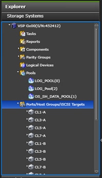
4. In the right pane of the Ports/Host Groups/iSCSI Targets window, click the Ports tab to see the list of ports.
5. Select all required ports and click Edit Ports.
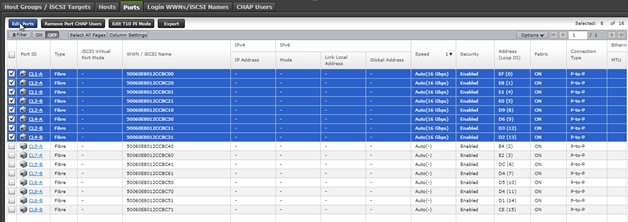
6. Enter the properties in the Edit Ports window, see Table 19 .
| For this: |
Enter this: |
| Port Security |
Select the check box and click the Enabled option. |
| Port Speed |
Select the check box and click the speed matching your connection speed. For example, select 32 Gbps. |
| Fabric |
Select the check box and click ON. |
| Connection Type |
Select the check box and click P-to-P. |
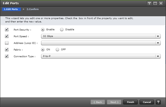
7. Click Finish on the 2. Confirm window.
8. Click Apply.
Hitachi NAS Platform Storage Configuration
The following section provides the storage configuration of the Hitachi NAS Platform to host HANA shared binaries and traces in scale-out installations.
Log into Storage Navigator
To log into the Storage Navigator, after installing the VSP G370 onsite and running all necessary cable connections and powering up the VSP G370, open Hitachi Storage Navigator to start the configuration, and follow these steps:
1. Access Hitachi Storage Navigator through a web browser.
2. https://<var_hitachi_svp_ip>/dev/storage/886000<Serial Number of Storage System>/emergency.do – for example, if Storage System SVP IP address is 192.168.93.21 and Serial Number of Storage System is 456789, the URL would be:
https://192.168.93.21/dev/storage/836000456789/emergency.do
3. Log into Hitachi Storage Navigator.
Configure Port Setting
To configure the host ports, follow these steps:
1. Open the Ports/Host Group/iSCSI Targets window.
2. In Storage Systems under the Explorer pane, expand the VSP Gx00 / VSP 5000 Series tree.
3. Click Ports/Host Groups/iSCSI Targets.
4. In the right pane of the Ports/Host Groups/iSCSI Targets window, click the Ports tab to see the list of ports.
5. Select all required ports where the FC Port of the HNAS is connected to the VSP Storage and click Edit Ports.
6. Enter the properties listed in the table below in the Edit Ports window.
| For this: |
Enter this: |
| Port Security |
Select the check box and click the Disabled option. |
| Port Speed |
Select the check box and click the speed matching your connection speed. For example, select 8 Gbps. |
| Fabric |
Select the check box and click OFF. |
| Connection Type |
Select the check box and click FC-AL. |
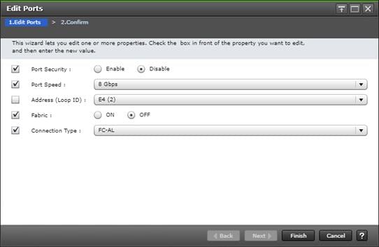
7. Click Finish on the 2. Confirm window.
8. Click Apply.
Create Pool Volumes
This procedure creates the Parity Groups and LDEVs using Hitachi Storage Navigator for the SAP HANA HNAS Pool which will be named HNAS_HDP_POOL will be created and used.
To create a pool volume, follow these steps:
1. Open the LDEV creation window.
2. In the General Tasks pane, click Create LDEVs. The 1 Create LDEVs dialog box opens.
3. Create Pool Volume LUN.
4. Create an LDEV.
5. Enter the values listed in the table below into the Create LDEVs dialog box.
| For this: |
Enter this: |
| Provisioning Type |
Click Basic |
| Drive Type/RPM |
Click SSD |
| RAID Level |
Click 1 (2D+2P) |
| Select Free Spaces |
Click the option |
| Parity Group |
Select the 1 (2D+2P) Parity Group |
| LDEV Capacity |
Type value 878 GB |
| Number of LDEVs per Free Space |
Type 4 for each RAID group |
| LDEV Name area |
Type the pool name HNAS_HDP_PoolVol as prefix and the next free number as int number, i.e. 1 for the first RAID group. |
| Options area |
In the LDKC:CU:DEV text box, type 00:00:3C |
| In the MPU assignment text box, select Auto |
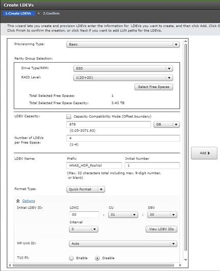
6. Click Add and then Finish.
7. Acknowledge the Warning by clicking OK.
8. When the Confirm window opens, confirm the selection again and click Apply.
Create Dynamic Provisioning Pools.
In the Storage Navigator session perform this procedure to create dynamic provisioning pools. This solution uses one dynamic provisioning pool for the HNAS Platform:
The name of the SAP HANA HNAS Pool will be defined as HNAS_HDP_POOL.
Follow the steps in this section to create the HNAS_HDP_POOL.
To create a dynamic provisioning pool, follow these steps:
1. From Pools, click Create Pools to open the 1. Create Pools window.

2. Enter the values listed in the table below in the Create Pools dialog box.
| For this: |
Enter this: |
| Pool Type |
Select Dynamic Provisioning |
| Multi-Tier Pool |
Disabled |
| Data Direct Mapping |
Disabled |
| Pool Volume Selection |
Click Manual |
| Pool Name |
HNAS_HDP_POOL |
| Initial Pool ID |
Type 2 for HNAS_HDP_Pool |
| Warning Threshold |
100 |
| Deletion Threshold |
100 |
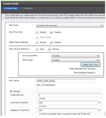
3. Select the pool volumes for the pool
4. Select Pool VOLs.
5. Select the volumes.
6. For HNAS_HDP_POOL, identify the pool volumes for the pool and select them. Click Add.
7. Click OK.
8. Click Add.
9. Click Finish on the 2. Confirm window.
10. Click Apply.
Provision the LUNS (Virtual Volumes)
This procedure creates the LDEVs using Hitachi Storage Navigator.
Create Virtual Volumes for HANA Shared File System and Map Ports
For SAP HANA Scale-Up the HANA Shared volume is used on a mapped LUN on a VSP Storage System.
The difference here on an SAP HANA Scale-Out environment is the central shared mount point for the SAP HANA binaries which is an NFS export on the Hitachi NAS Platform.
Use Hitachi Storage Navigator to create the HNAS virtual Pool LDEV and map it to specified Hitachi Virtual Storage Platform ports where the HNAS FC port are connected.
To create virtual Volumes from the POOL for the Hitachi NAS Platform follow the steps:
1. From Pools, click HNAS_HDP_POOL.
2. In the Virtual Volumes pane, click Create LDEVs. The first Create LDEVs dialog box opens.
3. Create HNAS virtual Pool Volumes
4. Create an LDEV.
5. Enter the values shown in below table in the Create LDEVs dialog box.
| For this: |
Enter this: |
| Provisioning Type |
Click Dynamic Provisioning |
| Drive Type/RPM |
Click SSD/- |
| RAID Level |
Click 1 (2D+2P) |
| Select Pool |
HNAS_HDP_POOL |
| LDEV Capacity |
878 GB |
| Number of LDEVs per Free Space |
Type 4 |
| Full Allocation |
Disabled |
| LDEV Name area |
For LDEV Name Prefix, type for the HNAS virtual Volumes LDEV name: HNAS_POOL_VVOL |
| For Initial Number type 1 |
|
| Options area |
In the LDKC:CU:DEV text box, for example type 00:00:40 |
| In the MPU assignment text box, select Auto |
6. Click Add.
7. Click Finish on the 2. Confirm window.
8. Click Apply.
Map the virtual Volumes (LUNs)
To map the virtual volume, from the Hitachi Storage Navigator go the General Task under the Storage System, and follow these steps:
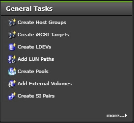
1. Click Add LUN Path.
2. From the Available LDEVs screen, select all 4x HNAS virtual Volumes which are begin with HNAS_POOL_VVOL.
3. Click Add.
4. Click Next.
5. From the Available Host Groups select all ports that are connected to the HNAS Nodes.
6. Click Add.
7. Click Next.
8. Click Finish then click Apply.
Hitachi NAS Platform Configuration
The following sections provides a detailed procedure for configuring the Hitachi NAS Platform to host HANA shared binaries and traces in scale-out installations.
Hitachi NAS Configuration
Complete these steps on both NAS nodes to setup the Hitachi NAS Platform 2-node cluster.
Virtual System Manager Unit (SMU) Installation
If the vSphere ESXi host is not already installed and operational, install the vSphere ESXi host onto a bare-metal host machine for your VM.
Use the Web browser to access the vSphere ESXi host and to operate its virtual machines (VM).
Deploy the SMU Operating System
To deploy and map the pre-configured SMU Operating System (OS) template, follow these steps:
1. Open a Web browser and log into the vSphere Client.
2. Right-click in the required location in the left-hand task bar and select Deploy OVF template.
3. Browse to the location of the SMU OS OVA file. Click Next.
4. Specify a unique virtual machine name and target location. Click Next.
5. Select the destination computer resource (host). Click Next.
6. Review the details and click Next.
7. Select the following virtual disk format: Thin Provision.
8. Select the storage (data store) and click Next.
9. Select the destination network (network card). Click Next.
10. Click Finish. The virtual image is deployed.
Increase Memory and CPU Resource Allocations
Before you add extra managed servers or clusters to the virtual SMU, increase the memory and the CPU resource allocations to reserve enough resources for each VM.
To increase memory and CPU resource allocations for four managed servers, follow these steps:
1. Power off the VM.
2. In the vSphere Client, right-click the VM and select Edit Settings to open the Virtual Machine properties dialog box.
3. Under Virtual Hardware, select CPU:
a. Set the CPU option either to four or set the Cores per Socket option to two to make a total of four sockets.
b. (Optional) Although CPU reservation is not required, you should increase the CPU reservation if the host supports it.
c. (Optional) If other VMs on the host can starve the virtual SMU of resources, you can set Shares for CPU (and Hard Disk) to High. This prioritizes the virtual SMU over VMs with a Normal or Low setting.
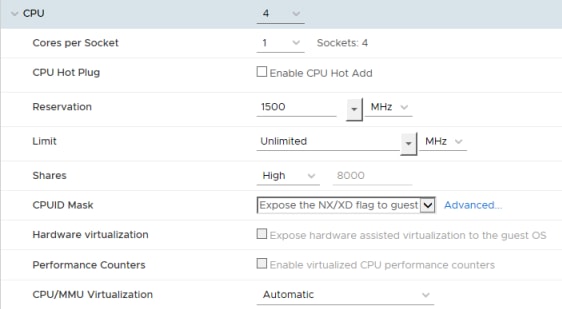
4. Under Virtual Hardware, select Memory:
a. Increase the memory value to 4GB.
b. (Optional Best Practice*) Set the reservation to 4096GB.
c. (Optional) If other VMs on the host can starve the virtual SMU of resources, you can set Shares for Memory to High.
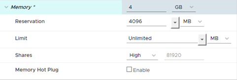
5. Click OK to save your changes, and then close the dialog box.
6. Right-click the VM and select Edit Settings again to verify that your memory and CPU settings are correct.
Install SMU Software
To install the SMU software, follow these steps:
1. Click the datastore icon in the left-hand task bar.

2. Select a datastore which is visible to the new SMU VM and click on the Files tab.
3. Upload the SMU software ISO file.
4. Right-click the new SMU VM and select Edit Settings to open the Virtual Machine properties dialog box.
a. Under Virtual Hardware, select the CD/DVD drive.
b. Select Datastore ISO File and click Browse.
c. Select the recently uploaded SMU software ISO file and click Open.
d. Verify that the Connect At Power On check box is selected and click OK.
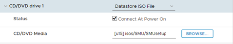
5. Power on the new SMU VM and launch a console.
6. Log in as root.
7. Run mount /media/cdrecorder.
8. Run /media/cdrecorder/autorun to start the installation. Note that the installation may take a few minutes to complete, after which the system reboots.
Install VMware Tools
To install the VMware tools, follow these steps:
1. Power on the VM
2. Right-Click the SMU VM and select Guest OS > Install VMware Tools….
3. Read the text and then click Mount.
4. Launch the console.
5. Login as root.
6. Run mount /media/cdrecoder.
7. Change to the /tmp directory. Then extract the contents of the tar file into a new directory call vmware-tools-distrib:
cd /tmp
tar -xvzf /media/cdrecorder/VMware Tools*.tar.gz
8. Change to the vmware-tools-distrib directory and start the installer:
cd vmware-tools-distrib
./vmware-install.pl
9. Follow the prompts and confirm the default settings.
10. When the script is complete, type reboot.
11. To confirm that the VMware Tools have been installed, click the VM Summary tab.
Configure the SMU Software
After you have installed the virtual SMU software, configure the virtual SMU network settings by following these steps:
1. In the console, log in as root.
2. Run smu-config, and then follow the prompts to configure the network.
3. Review all of the settings, and then type Y to confirm. The script sets up the network interfaces and the default properties, and then the SMU reboots.
4. On your laptop or desktop, open a web browser and point it to one of the SMU IP addresses.
5. Log into NAS Manager as admin. The NAS Manager Web GUI opens.
Perform Hitachi NAS Platform Initial Configuration
Configure the two Hitachi NAS Platform nodes separately. Use the nas-preconfig command to perform the initial configuration of Hitachi NAS platform nodes.
To do the initial configuration for Hitachi NAS Platform 4060, follow these steps:
1. Connect the VGA Port with a Monitor and the USB Keyboard to any USB Port on the node
2. Log in using these user credentials:
User Name: root
Password: nasadmin
3. Make the initial configuration settings for the Hitachi NAS Platform 4060 with the setup wizard.
4. To start the wizard, type this command:
nas-preconfig
5. Using the wizard, set the parameters listed in Table 20 .
Table 20 HNAS Initial Configuration Parameters for HNAS node 1 / HNAS node 2
| Configuration Requirements |
Configuration Values |
| Admin Service Private (eth1) IP address |
192.168.93.32 / 192.168.93.35 |
| Admin Service Private (eth1) Netmask |
255.255.255.0 |
| Optional Admin Service Public (eth0) IP address |
Press Enter without entering a value |
| Optional Physical Node (eth1) IP address |
192.168.93.33 / 192.168.93.34 |
| Physical Node (eth1) Netmask |
255.255.255.0 |
| Gateway |
192.168.93.1 |
| Domain name (without the host name) |
(Customer specific) |
| Hostname (without the domain name) |
hnas1 / hnas2 |
6. To confirm the settings, type Y and press Enter
7. To reboot the server, type this command:
reboot -f
8. After the system reboots, verify that the eth1 has the IP address 192.168.93.32 and the optional IP address of 192.168.93.33
9. Log into the system and check the settings by doing one of the following:
- Log on with the user name root with the password nasadmin and type the following command:
ifconfig
- Log on with the user name supervisor and the password supervisor and type the following command:
evs list
10. If the eth1 IP addresses are not correct, follow these steps:
a. Request a reset key for the Hitachi NAS Platform 4060
b. Reset Hitachi NAS Platform 4060 to the factory defaults
c. Repeat steps 1-10 in Node 1.
For Node 2 repeat the Initial Configuration with the nas-preconfig command and with the appropriate parameters.
Add Hitachi NAS Platforms as Managed Servers on the Virtual SMU
Add the two Hitachi NAS Platform 4060 nodes, hnas1 and hnas2, separately.
To add each node as a managed server on the vSMU, follow these steps:
1. Open the NAS Manager on the client system for the vSMU.
2. Type this IP Address in the address bar of the web browser: https://192.168.93.32
3. Log on with these user credentials:
User Name: admin
Password: nasadmin
4. Using the wizard, add the hnas1 as managed server from the NAS Manager.
a. One the home page, click SMU Administration and then Managed Server
b. Click Add and then follow the prompts
c. For the Server IP address, type in the following: 192.168.93.32
d. For the Server username, type in the following: supervisor
e. For the Server password, type the following (same as username): supervisor
f. Click OK.
The node hnas1 is now in Server Status Console on the NAS Manager home screen.
To add the node 2 with the hostname hnas2, repeat step 2 with the appropriate IP addresses.
Install License Keys on the Hitachi NAS Platform 4060 Servers
To add the License Keys, from the NAS Manager, follow these steps:
1. Navigate to Home > Server Settings > License Keys.
2. Click add.
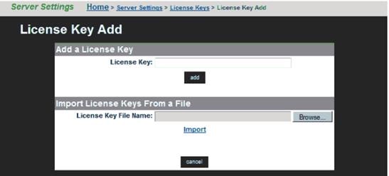
3. To import the key, click Browse and choose the File then click Import.
Setup the Hitachi NAS Platform Cluster
To set up the Hitachi NAS Platform cluster, follow these steps.
1. Open the NAS Manager on the client server for the vSMU.
2. Type this IP address in the address bar of the web browser: https://192.168.168.93.32
3. Log on with these user credentials
User Name: admin
Password: nasadmin
4. Add hnas1 to the cluster.
5. On the Server Status Console, scroll down and click hnas1
6. To start the cluster wizard, click Home, then click Server Settings and then click Cluster Wizard.
7. If asked to log on to hnas1 use these user credentials and then click Next.
User Name: supervisor
Password: supervisor
8. Provide the following information:
· For Cluster name, type the following: CLUST1
· For Cluster Node IP Address, type the following: 192.168.93.33
· For Subnet Mask, type the following: 255.255.255.0
· For Select the Quorum Device, click smu1
9. For the message about automatically rebooting the server, click OK.
The node hnas1 reboots.
10. Add the node hnas2 to the Cluster.
11. After hnas1 reboots, when asked whether to add an additional cluster node now, click Yes.
12. For Select a server to join the cluster, click hnas2 at 192.168.93.34
13. Log on with these user credentials and then click Next:
User Name: supervisor
Password: supervisor
14. In the wizard, review the details in the Cluster to Join/Joining node and then click Finish.
A message displays stating the request to join the server was successful and the new cluster node is rebooting.
![]() Wait approximately 10 minutes for the server to join the cluster.
Wait approximately 10 minutes for the server to join the cluster.
15. Verify that hnas1 and hnas2 are displayed in Cluster Nodes and name them.
16. In the NAS Manager, click Server settings and then Cluster Configuration:
a. Verify that hnas1 and hnas2 display in the Cluster Nodes
b. Name hnas1 as follows: CLUST1-1
c. Name hnas2 as follows: CLUST1-2
Create a Link Aggregation
These procedures describe how to configure the public data network.
To create a link aggregation, follow these steps:
1. From the NAS Manager home page for the virtual SMU, click Network Configuration and then click Link Aggregation.
2. Click Add.
3. For the link aggregate name, click ag1
4. To add ports under Available Ports, select the tg1 and tg2 check boxes.
5. For Use of NO LACP, click No (None).
6. For Port Level Load Balancing, click Normal (the default value).
Create Enterprise Virtual Server
Like a physical server, an enterprise virtual server contains these features:
· Has an IP Address
· Contains file systems
· Support CIFS shares and NFS exports
To create one enterprise virtual servers, follow these steps:
1. From the NAS Manager home page for the virtual SMU, click Server Settings and then click EVS Management.
2. Create EVS1:
a. Click Add.
b. Type this for the label name: EVS1
c. From the Preferred Cluster Node list, click CLUST1-1.
d. From the IP address, type the following: 192.168.110.40
e. From the Subnet mask list, click 255.255.255.0
f. To assign 10 GbE ports, from the Port list, click ag1 and then click OK.
Set Parameters on the Hitachi NAS Platform 4060
Perform the following procedures to set the parameters on the Hitachi NAS Platform 4060.
Configure the Hitachi NAS Platform Fibre Channel Ports
To configure the Fibre Channel ports on the Hitachi NAS Platform, follow these steps:
1. On the client server, open a SSH terminal session to the vSMU. Connect to the vSMU command line interface with these credentials:
User Name: manager
Password: nasadmin
2. To select which Hitachi NAS Platform to configure, type: 1
3. To configure the Fibre Channel ports as Node-Loop ports on the cluster, type:
cn all fc-link-type -t NL
Set the MTU Size
To set MTU size, follow these steps:
1. To select the Hitachi NAS Platform to be configured, type: 1
2. To set the MTU Size, type:
cn all ipadv -m 9000
Configure Drives, Storage Pools and File Systems
To configure system drives, storage pools and the file systems for use by the scale-out HANA system, follow these steps:
1. Select the system drives.
2. In the NAS Manager home page for the virtual SMU, click Storage Management and then click System Drives.
3. Select the check boxes for the system drives to be used from Table 21 and the click Allow Access.
| Number of SAP HANA Nodes |
System Drives |
||
| 1,5 TB RAM |
3 TB RAM |
6 TB RAM |
|
| Up to 4 HANA nodes |
Use 4 systems drives (*) |
||
| Up to 8 HANA nodes |
|||
| Up to 12 HANA nodes |
|||
| Up to 16 HANA nodes |
|||
(*) The capacity is based on the number of active SAP HANA worker nodes.
4. Create a unified storage pool:
a. From the virtual SMU NAS Manager home page, click Storage Management and then click Storage Pools.
b. Click Create.
c. On the next screen, click An Untiered Storage Pool.
d. Select all system drives for the storage pool.
e. Type the following for the storage pool label: HANABIN_<SID>
f. Double-check the configuration
g. Click Create.
h. When asked if you want to add a file system to your new storage pool, click Yes.
i. The Create File screen opens.
5. Create the file system:
a. Select the option of the storage pool HANABIN_<SID> to create the file system then click Next.
b. Specify the Size Limit from Table 22 .
Table 22 Storage Pool Size Limits
| Number of Active SAP HANA Nodes |
Size limit |
||
| 1,5 TB RAM |
3 TB RAM |
6 TB RAM |
|
| Up to 4 HANA nodes |
The capacity is based on the number of SAP HANA Nodes and memory size Use the max available Pool Size Limit of HNAS |
||
| Up to 8 HANA nodes |
|||
| Up to 12 HANA nodes |
|||
| Up to 16 HANA nodes |
|||
c. Choose Allocate On Demand.
d. Specify the Label Name: HANA_SHARED_<SID>
e. For Assign to EVS, click EVS1 from the list.
f. To specify the block size, click the 32KB option
g. Click OK.
Thin Provision for the File System
To set the thin provision for the file system, follow these steps:
1. On the client server, open an SSH terminal session for the vSMU. Connect to the vSMU command line interface with these user credentials:
User Name: manager
Password: nasadmin
2. To select the Hitachi NAS Platform to be configured, type: 1
3. To set the thin provision for the file system, run the following command:
filesystem-thin HANA_SHARED_<SID> on
4. To verify that thin provision is enabled for the file system, run the following command:
filesystem-limits HANA_SHARED_<SID>
The output should show the value enabled for Thin provision
Set the Superflush Values
To set the superflush values (to set the system drive width and stripe size), follow these steps:
1. On the client server, open an SSH terminal session for virtual SMU. Connect to the virtual SMU command line interface with these user credentials:
User Name: manager
Password: nasadmin
2. To select the Hitachi NAS Platform to be configured, type: 1
3. To set the superflush optimal value of 3 and stipe size of 128, type the following:
- HANA node configuration
- Setting:
cn all sd-set -w 3 -s 128 0-3
Create the NFS Exports
To create NFS exports, follow these steps (SID is the HANA database instance ID):
1. From the NAS Manager home page for the virtual SMU, click File Services and then click NFS exports.
2. Click Add.
3. For EVS/File system, click Choose.
4. For File System, click hana_shared_<SID>.
5. For Export Name, type: /hana_shared_<SID>
6. For Path, type: /hana/shared/<SID>
7. For Access configuration, type exactly as shown: (rw,norootsquash)
8. Click OK.
Cisco UCS Configuration
This section describes the specific configurations for Cisco UCS servers to address the SAP HANA requirements.
It is beyond the scope of this document to explain detailed information about the Cisco UCS infrastructure. Detailed configuration guides are available at: https://www.cisco.com/c/en/us/support/servers-unified-computing/ucs-manager/products-installation-and-configuration-guides-list.html
The prerequisite for the Cisco UCS configuration is the physical cabling which is detailed in section Physical Cabling.
Firmware Upgrade to Cisco UCS Manager Release 4.0(4b)
The validated reference architecture is based on the Cisco UCS Manager Release 4.0(4b). To upgrade the Cisco UCS Manager software and all endpoints in the UCS domain like the Cisco UCS Fabric Interconnect software to version 4.0(4b) consult the Cisco UCS Manager Firmware Management Guide from Cisco UCS Manager Install and Upgrade Guides.
Initial Setup of Cisco UCS 6332-16UP FI-A
The initial configuration dialogue for the Cisco UCS 6332-16UP Fabric Interconnects (FI) provides the primary information to the first fabric interconnect, with the second one taking over most settings after joining the cluster.
Connect to the console port of FI A, which will be the primary member in the cluster. Power on FI A and leave the secondary FI B powered off for now. Follow the steps in the basic system configuration dialog:
---- Basic System Configuration Dialog ----
This setup utility will guide you through the basic configuration of the
system. Only minimal configuration including IP connectivity to the Fabric
interconnect and its clustering mode is performed through these steps.
Type Ctrl-C at any time to abort configuration and reboot system.
To back track or make modifications to already entered values, complete input
Till end of section and answer no when prompted to apply configuration.
Enter the configuration method. (console/gui) ? console
Enter the setup mode; setup newly or restore from backup. (setup/restore) ? setup
You have chosen to setup a new Fabric interconnect. Continue? (y/n): y
Enforce strong password? (y/n) [y]: <enter>
Enter the password for "admin": <var_ucs_admin_pw>
Confirm the password for "admin": <var_ucs_admin_pw>
Is this Fabric interconnect part of a cluster(select 'no' for standalone)? (yes/no) [n]: yes
Enter the switch fabric (A/B) []: A
Enter the system name: <var_ucs_clustername>
Physical Switch Mgmt0 IP address : <var_ucsa_mgmt_ip>
Physical Switch Mgmt0 IPv4 netmask : <var_oob_mask>
IPv4 address of the default gateway : <var_oob_gateway>
Cluster IPv4 address : <var_ucs_mgmt_ip>
Configure the DNS Server IP address? (yes/no) [n]: y
DNS IP address : <var_nameserver_ip>
Configure the default domain name? (yes/no) [n]: y
Default domain name : <var_dns_domain_name>
Join centralized management environment (UCS Central)? (yes/no) [n]: n
Following configurations will be applied:
Switch Fabric=A
System Name=<var_ucs_clustername>
Enforced Strong Password=yes
Physical Switch Mgmt0 IP Address=<var_ucsa_mgmt_ip>
Physical Switch Mgmt0 IP Netmask=<var_oob_mask>
Default Gateway=<var_oob_gateway>
Ipv6 value=0
DNS Server=<var_nameserver_ip>
Domain Name=<var_dns_domain_name>
Cluster Enabled=yes
Cluster IP Address=<var_ucs_mgmt_ip>
NOTE: Cluster IP will be configured only after both Fabric Interconnects are
initialized. UCSM will be functional only after peer FI is configured
in clustering mode.
Apply and save the configuration (select 'no' if you want to re-enter)? (yes/no): yes
Wait for the login prompt to make sure that the configuration has been saved. This completes the configuration of FI A. Leave the Fabric Interconnect powered on. Connect to the console port of FI B and power on the second FI.
Initial Setup of Cisco UCS 6332-16UP FI-B
Follow the steps in the basic system configuration dialog of FI B:
---- Basic System Configuration Dialog ----
This setup utility will guide you through the basic configuration of the
system. Only minimal configuration including IP connectivity to the Fabric
interconnect and its clustering mode is performed through these steps.
Type Ctrl-C at any time to abort configuration and reboot system.
To back track or make modifications to already entered values, complete input
till end of section and answer no when prompted to apply configuration.
Enter the configuration method. (console/gui) ? console
Installer has detected the presence of a peer Fabric interconnect. This Fabric
interconnect will be added to the cluster. Continue (y/n) ? y
Enter the admin password of the peer Fabric interconnect: <var_ucs_admin_pw>
Connecting to peer Fabric interconnect... done
Retrieving config from peer Fabric interconnect... done
Peer Fabric interconnect Mgmt0 IPv4 Address: <var_ucsa_mgmt_ip>
Peer Fabric interconnect Mgmt0 IPv4 Netmask: <var_oob_mgmt_mast>
Cluster IPv4 address : <var_ucs_mgmt_ip>
Peer FI is IPv4 Cluster enabled. Please Provide Local Fabric Interconnect
Mgmt0 IPv4 Address
Physical Switch Mgmt0 IP address : <var_ucsb_mgmt_ip>
Apply and save the configuration (select 'no' if you want to re-enter)? (yes/no):yes
Wait for the login prompt to make sure that the configuration has been saved.
Cisco UCS Manager Setup
Log into Cisco UCS Manager
To log into the Cisco Unified Computing System environment, follow these steps:
1. Open a web browser and navigate to the Cisco UCS 6332 Fabric Interconnect cluster IP address.
2. Click Launch UCS Manager.
3. If prompted to accept security certificates, accept as necessary.
4. When prompted, enter admin as the user name and enter the administrative password.
5. Click Login to log into the Cisco UCS Manager.
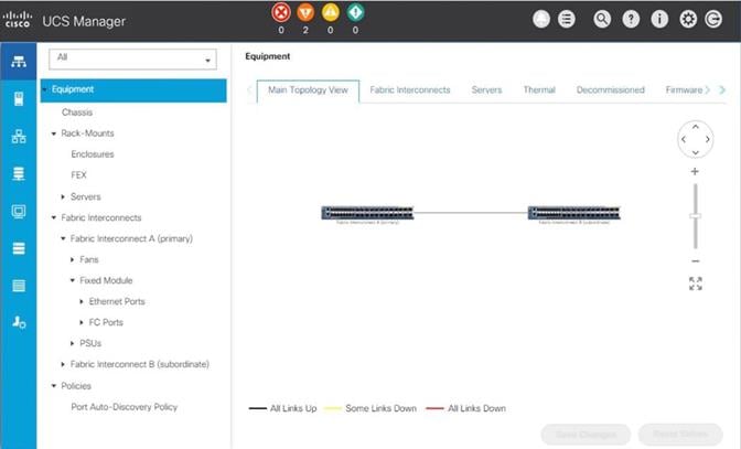
Anonymous Reporting
During the first connection to the Cisco UCS Manager GUI, a pop-up window appears requesting authorization to collect feature configuration and usage statistics. All data will be sent anonymously and helps to prioritize future feature or improvement developments.
To configure anonymous reporting, follow these steps:
1. In the Anonymous Reporting window, select whether to send anonymous data to Cisco for improving future products, and provide the appropriate SMTP server gateway information:
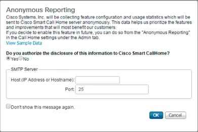
2. If you want to enable or disable Anonymous Reporting in the future, use the configuration menu within Cisco UCS Manager under: Admin -> Communication Management -> Call Home in the tab Anonymous Reporting.
Synchronize Cisco UCS to NTP
To synchronize the Cisco UCS domain to the NTP server, follow these steps:
1. In the Navigation pane, click Admin.
2. Select Timezone Management drop-down list and click Timezone.
3. In the Properties pane, select the appropriate time zone in the Timezone menu.
4. Click Save Changes, and then click OK.
5. Click Add NTP Server.
6. Enter <var_global_ntp_server_ip> and click OK.
Configure Cisco UCS Blade Servers
For the Cisco UCS 2300 Series Fabric Extenders, two configuration options are available: pinning and port-channel.
SAP HANA node communicates with every other SAP HANA node using multiple I/O streams and this makes the port-channel option a highly suitable configuration. SAP has defined a single-stream network performance test as part of the hardware validation tool (TDINetServer/TDINetClient).
However, with the new 40Gb network speed it is also possible to stay with the default Port-Channel connection policy setting.
Chassis Discovery Policy
Setting the discovery policy simplifies the addition of the Cisco UCS B-Series chassis. To modify the chassis discovery policy, follow these steps:
1. In the Navigation pane, click Equipment.
2. In the right pane, click the Policies tab.
3. Under Global Policies, set the Chassis/FEX Discovery Policy to match the number of uplink ports that are cabled between the chassis or fabric extenders (FEXes) and the fabric interconnects. Set the Link Grouping Preference to Port Channel.
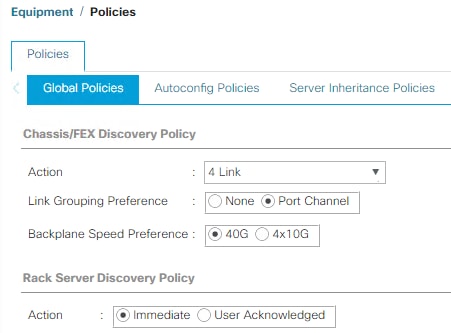
4. Click Save Changes.
5. Click OK.
Fabric Interconnect Information Policy
Enable the information policy on the Fabric Interconnect to view the SAN and LAN neighbors of the Fabric Interconnect.
1. In the Navigation pane, click Equipment.
2. In the Equipment tab, click Policies.
3. Under Global Policies, scroll down to Info Policy and change the action to enabled.
4. Click Save Changes.
5. Click OK.
Configure Server Ports
Configure Fabric Interconnect ports which are connected to downlink IOM Fabric Extender (FEX) cards as server ports:
1. In the Navigation pane, click Equipment.
2. Select Equipment > Fabric Interconnects > Fabric Interconnect A (primary) > Fixed Module.
3. Click Ethernet Ports.
4. On the main pane, select the ports that are connected to the chassis and / or to the Cisco UCS B-Series Server (two per FI), right-click them, and select Configure as Server Port.
5. Click Yes to confirm server ports and click OK.
6. Verify that the ports connected to the chassis and / or to the Cisco UCS B-Series Server are now configured as server ports.
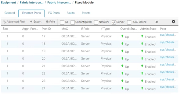
7. Select Equipment > Fabric Interconnects > Fabric Interconnect B (subordinate) > Fixed Module.
8. Click Ethernet Ports.
9. On the main pane, select the ports that are connected to the chassis or to the Cisco UCS B-Series Server (two per FI), right-click them, and select Configure as Server Port.
10. Click Yes to confirm server ports and click OK.
Configure FC SAN Uplink Ports
Configure the ports connected to the MDS as FC SAN Uplink Ports. This step creates the first set of ports from the left for example, ports 1-6 of the Fixed Module for FC uplinks and the rest for Ethernet uplinks to N9Ks.
![]() While configuring the Fixed Module Ports, the slider bar movement enables sets of ports from the left of the module as FC ports. The remainder is available for Ethernet Uplinks. This step used 4 ports for uplink to MDS, it would be enough to configure first set of 6 ports as FC ports.
While configuring the Fixed Module Ports, the slider bar movement enables sets of ports from the left of the module as FC ports. The remainder is available for Ethernet Uplinks. This step used 4 ports for uplink to MDS, it would be enough to configure first set of 6 ports as FC ports.
1. In the Navigation pane, click Equipment.
2. Select Equipment > Fabric Interconnects > Fabric Interconnect A.
3. In the General tab, click Actions > Configure Unified Ports. Choose Yes for the warning pop-up
4. In the configure unified ports Navigation pane move the slider bar to right to enable the first set of 6 ports for FC Uplink Role. Click OK.
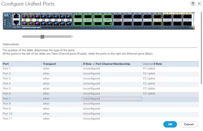
5. Configuring the unified ports require immediate reboot. Click Yes on the warning pop-up to reboot the Fabric Interconnect.
6. In the Navigation pane, select Equipment > Fabric Interconnects > Fabric Interconnect B and click in the General tab on Actions > Configure Unified Ports. Choose Yes for the warning pop-up In Cisco UCS Manager.
7. In the configure unified ports Navigation pane move the slider bar to right to enable the first set of 6 ports for FC Uplink Role. Click OK.
8. Configuring the unified ports require immediate reboot. Click Yes on the warning pop-up to reboot the Fabric Interconnect.
9. Once the FIs are accessible again after their restart, re-login to Cisco UCS Manager.
Configure Ethernet Uplink Ports
To configure the ethernet uplink ports connected to the N9K Ethernet Uplink Ports, follow these steps:
1. In the Navigation pane, click Equipment.
2. Select Equipment > Fabric Interconnects > Fabric Interconnect A (primary) > Fixed Module.
3. In the right pane, select the Ethernet Ports tab.
4. Select ports that are connected to the Cisco Nexus switches, right-click them, and select Configure as Uplink Port.
![]() Select ports in the range 17-34 for the 40GE Uplink Port connectivity.
Select ports in the range 17-34 for the 40GE Uplink Port connectivity.
5. Click Yes to confirm uplink ports and click OK.
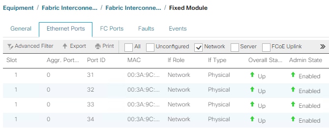
6. In the Navigation pane, select Equipment > Fabric Interconnects > Fabric Interconnect B (subordinate) > Fixed Module.
7. In the right pane, select the Ethernet Ports tab.
8. Select ports that are connected to the Cisco Nexus switches, right-click them, and select Configure as Uplink Port.
9. Click Yes to confirm the uplink ports and click OK.
Acknowledge Cisco UCS Chassis
To acknowledge all Cisco UCS chassis, follow these steps:
1. In the Navigation pane, click Equipment.
2. Expand Chassis and select each chassis that is listed. Right-click each chassis and select Acknowledge Chassis.
3. Ensure the discovery completes successfully and no major or critical faults are reported for any of the servers.
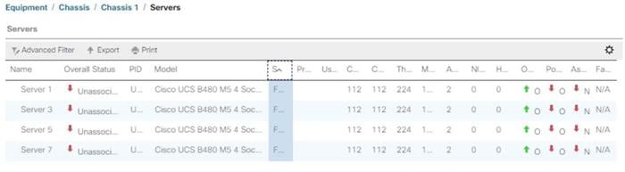
Power Policy
To run Cisco UCS with two independent power distribution units, the redundancy must be configured as Grid. Follow these steps:
1. In the Navigation pane, click Equipment.
2. In the right pane, click the Policies tab.
3. In the Global Policies tab, set the Redundancy field in Power Policy to Grid.
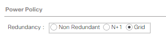
4. Click Save Changes.
5. Click OK.
Power Control Policy
The Power Capping feature in Cisco UCS is designed to save power with a legacy data center use case. This feature does not contribute much to the high-performance behavior of SAP HANA. By choosing the option “No Cap” for power control policy, the SAP HANA server nodes will not have a restricted power supply. It is recommended to have this power control policy set to ensure enough power is available for high performance and critical applications like SAP HANA.
To create a power control policy for the Cisco UCS environment, follow these steps:
1. In the Navigation pane, click Servers.
2. Select Policies > root > Power Control Policies.
3. Right-click Power Control Policies and select Create Power Control Policy.
4. Enter HANA as the Power Control Policy name. (Optional) Provide a description.
5. Set Fan Speed Policy to Performance.
6. Change the Power Capping setting to No Cap.
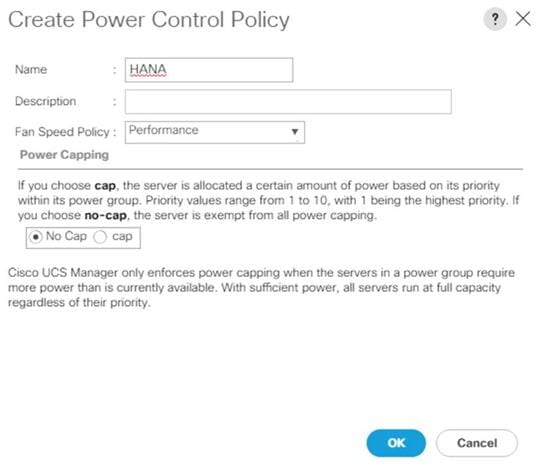
7. Click OK to create the power control policy.
8. Click OK
Create New Organization
For secure multi-tenancy within the Cisco UCS domain, create a logical entity known as organization.
To create an organization unit, follow these steps:
1. Select the Quick actions button on the right top pane.
2. From the drop-down list select Create Organization.
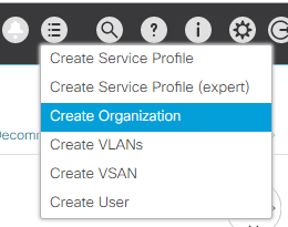
3. Provide an organization name, for example T01-HANA
4. (Optional) Provide an organization description.
5. Click OK to create the Organization.
Create Pools
Add Block of IP Addresses for KVM Access
To create a block of IP addresses for server Keyboard, Video, Mouse (KVM) access in the Cisco UCS environment, follow these steps:
![]() This block of IP addresses should be in the same subnet as the management IP addresses for the Cisco UCS Manager.
This block of IP addresses should be in the same subnet as the management IP addresses for the Cisco UCS Manager.
1. In the Navigation pane, click LAN.
2. Select Pools > root > IP Pools > IP Pool ext-mgmt.
3. In the General tab, click Create Block of IPv4 Addresses.
4. Enter the starting IP address of the block and the number of IP addresses required as well as the subnet and gateway information.
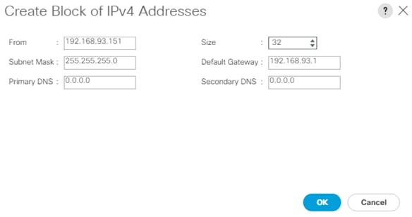
5. Click OK to create the IP block.
6. Click OK in the confirmation message.
Create MAC Address Pools
To configure the necessary MAC address pools for the Cisco UCS environment, follow these steps:
1. In the Navigation pane, click LAN.
2. Select Pools > root > MAC Pools.
3. In this procedure, two MAC address pools are created, one for each switching fabric.
4. Right-click MAC Pools under the root
5. Select Create MAC Pool to create the MAC address pool.
6. Enter FI-A as the name of the MAC pool.
7. (Optional) Enter a description for the MAC pool.
8. Choose Assignment Order Sequential.
9. Click Next.
10. Click Add.
11. Specify a starting MAC address.
![]() The recommendation is to place 0A in the second-last octet of the starting MAC address to identify all the MAC addresses as Fabric Interconnect A addresses.
The recommendation is to place 0A in the second-last octet of the starting MAC address to identify all the MAC addresses as Fabric Interconnect A addresses.
12. Specify a size for the MAC address pool that is large enough to support the available blade or server resources.
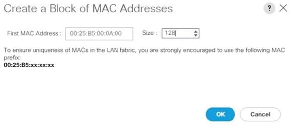
13. Click OK.
14. Click Finish.
15. In the confirmation message, click OK.
16. Repeat steps 4 to 16 for the Fabric Interconnect B.
![]() It is recommended to use the next to last octet of the starting MAC address to identify all MAC addresses of this pool belonging to a specific fabric interconnect. In the lab environment we use 0A for the MAC address pool of fabric A and 0B for the MAC address pool of fabric B.
It is recommended to use the next to last octet of the starting MAC address to identify all MAC addresses of this pool belonging to a specific fabric interconnect. In the lab environment we use 0A for the MAC address pool of fabric A and 0B for the MAC address pool of fabric B.
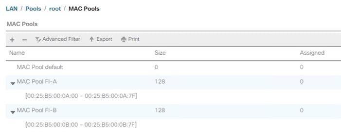
Create WWNN Pool
To configure the necessary WWNN pool for the Cisco UCS environment, follow these steps:
1. In the Navigation pane, click SAN.
2. Select Pools > root > WWNN Pools.
3. Right-click WWNN Pools and select Create WWNN Pool.
4. Enter HANA-Servers as the name of the WWNN pool.
5. (Optional) Enter a description for the WWNN pool.
6. Choose Assignment Order Sequential.
7. Click Next.
8. Click Add.
9. Specify a starting WWNN address.
![]() The recommendation is to place AB in the third-last octet of the starting WWNN address to ensure uniqueness.
The recommendation is to place AB in the third-last octet of the starting WWNN address to ensure uniqueness.
10. Specify a size for the WWNN pool that is enough to support the available blade or server resources.

11. Click OK.
12. Click Finish.
13. In the confirmation message, click OK.
Create WWPN Pool
To configure the two required WWPN pools, one per fabric interconnect, follow these steps:
1. In the Navigation pane, click SAN.
2. Select Pools > root > WWPN Pools.
3. Right-click WWPN Pools and select Create WWPN Pool.
4. Enter FI-A as the name of the WWPN pool.
5. (Optional) Enter a description for the WWPN pool.
6. Choose Assignment Order Sequential.
7. Click Next.
8. Click Add.
9. Specify a starting WWPN address.
![]() The recommendation is to place 0A in the second-last octet of the starting MAC address to identify all WWPN addresses as Fabric Interconnect A addresses.
The recommendation is to place 0A in the second-last octet of the starting MAC address to identify all WWPN addresses as Fabric Interconnect A addresses.
10. Specify a size for the WWPN address pool that is large enough to support the available blade or server resources.
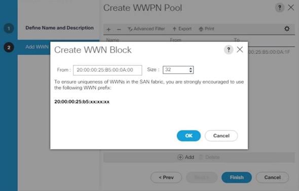
11. Click OK.
12. Click Finish.
13. Repeat steps 3 to 13 for the Fabric Interconnect B.
![]() It is recommended to place 0A in the next to second-last octet of the starting WWPN address to identify all the WWPN addresses in this pool as fabric A addresses. Place 0B in the second-last octet of the starting WWPN address to identify all the WWPN addresses in this pool as fabric B addresses.
It is recommended to place 0A in the next to second-last octet of the starting WWPN address to identify all the WWPN addresses in this pool as fabric A addresses. Place 0B in the second-last octet of the starting WWPN address to identify all the WWPN addresses in this pool as fabric B addresses.
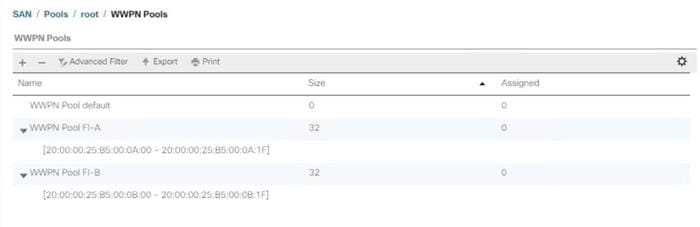
Create UUID Suffix Pool
To configure the necessary universally unique identifier (UUID) suffix pool for the Cisco UCS environment, follow these steps:
1. In the Navigation pane, click Servers.
2. Select Pools > root > UUID Suffix Pools.
3. Right-click UUID Suffix Pools and select Create UUID Suffix Pool.
4. Enter HANA-UUID as the name of the UUID suffix pool.
5. (Optional) Enter a description for the UUID suffix pool.
6. Keep the Prefix as the Derived option.
7. Choose Assignment Order Sequential.
8. Click Next.
9. Click Add to add a block of UUIDs.
10. Keep the ‘From’ field at the default setting.
11. Specify a size for the UUID block that is large enough to support the available blade or server resources.
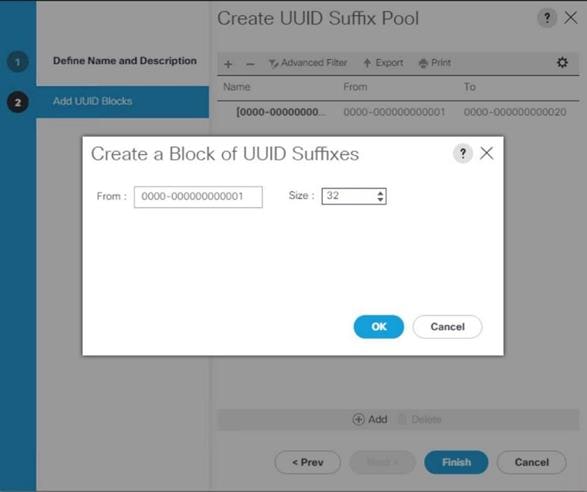
12. Click OK.
13. Click Finish.
14. Click OK.
Set Packages and Policies
Firmware management policies allow the administrator to select the corresponding packages for a given server configuration. These policies often include packages for adapter, BIOS, board controller, FC adapters, host bus adapter (HBA) option ROM, and storage controller properties.
To create a firmware management policy for a given server configuration in the Cisco UCS environment, follow these steps:
1. In the Navigation pane, click Servers.
2. Select Policies > root > Host Firmware Packages.
3. Right-click Host Firmware Packages and select Create Host Firmware Package.
4. Enter HANA-FW as the name of the host firmware package.
5. Leave the option Simple to configure the Host Firmware Package.
6. Select the version 4.0(4b)B for the Blade Package and 4.0(4b)C for Rack Packages.
![]() The Firmware Package version depends on the UCSM software release installed.
The Firmware Package version depends on the UCSM software release installed.
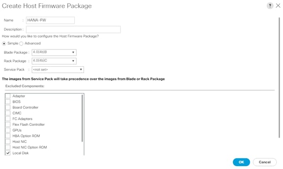
7. Click OK to create the host firmware package.
8. Click OK.
Create Server BIOS Policy
To get best performance for HANA it is required to configure the Server BIOS accurately. To create a server BIOS policy for the Cisco UCS environment, follow these steps:
1. In the Navigation pane, click Servers.
2. Select Policies > root > BIOS Policies.
3. Right-click BIOS Policies and select Create BIOS Policy.
4. Enter HANA-BIOS as the BIOS policy name.
5. Select “Reboot on BIOS Settings Change”. Click OK.
6. Select the new BIOS policy HANA-BIOS.
7. In the right pane, select the Main tab. Change the BIOS Setting Quiet Boot to disabled.

8. In the right pane, select the Advanced tab.
![]() CPU C-States are processor idle power saving states. The recommendation from SAP for SAP HANA is to allow C0 and C1 states in certain conditions using saptune to tune the operating system. On BIOS level disable all processor C-Stated to run SAP HANA with best performance.
CPU C-States are processor idle power saving states. The recommendation from SAP for SAP HANA is to allow C0 and C1 states in certain conditions using saptune to tune the operating system. On BIOS level disable all processor C-Stated to run SAP HANA with best performance.
9. On the Advanced tab, select the Processor sub-tab.
10. Set the CPU Performance value to “HPC”.
11. Set Power Technology to “Performance”.
12. Set Energy Performance to “Performance”.
13. Ensure processor C-States are disabled.
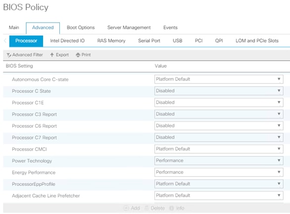
14. In the RAS Memory sub-tab, set Performance Mode for LV DDR Mode, enable the NUMA optimized setting and set the Memory RAS configuration to maximum-performance.
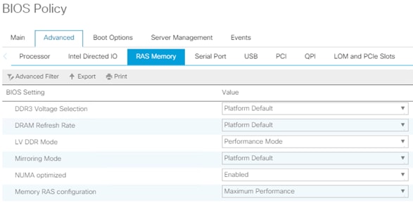
15. In the Serial Port sub-tab, set Serial Port A enable to enabled.
16. In the right pane, select the Server Management tab.
17. Set the Baud rate to 115.2k, the console redirection to Serial Port A, enable the Legacy OS redirection and change the Terminal Type to VT100-PLUS. This setting is required for Serial Console Access over LAN to all SAP HANA servers.
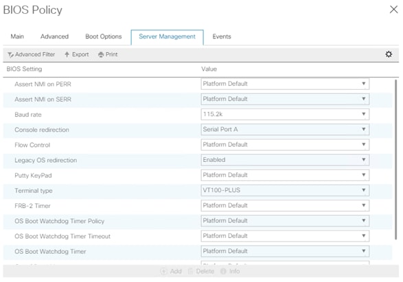
18. Click Save Change to modify BIOS Policy.
19. Click OK.
Create Serial over LAN Policy
The Serial over LAN policy is required to get console access to all SAP HANA servers through SSH from the management network. This is a requirement in case of server hang situations or Linux kernel crashes when a crash dump is required. To configure the policy, follow these steps:
1. In the Navigation pane, click Servers.
2. Select Policies > root > Serial over LAN Policies.
3. Right-click the Serial over LAN Policies and select Create Serial over LAN Policy.
4. Enter SoL-Console as policy name.
5. Enable Serial over LAN State.
6. Change the speed to 115200.
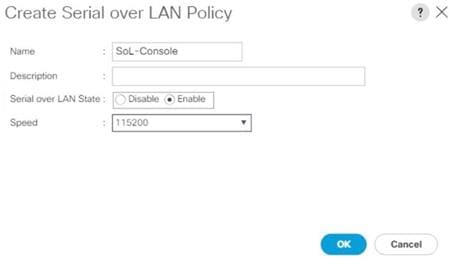
7. Click OK.
Update Default Maintenance Policy
It is recommended to update the default Maintenance Policy with the Reboot Policy “User Ack” for the SAP HANA server. This policy setting ensures to wait for the administrator acknowledgement for a server reboot prior of configuration changes will take effect.
To update the default Maintenance Policy, follow these steps:
1. In the Navigation pane, click Servers.
2. Select Policies > root > Maintenance Policies.
3. Select the default maintenance policy.
4. Set Reboot Policy to User Ack.
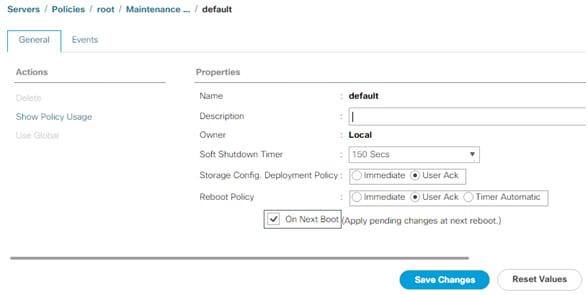
5. Click Save Changes.
6. Click OK to accept the change.
Adapter Policy Configuration – HANA
This section describes the Ethernet Adapter Policy with optimized Interrupts values. This policy must be used for the SAP HANA internal network in SAP HANA Scale-Out deployments to provide best network performance.
To create an Ethernet Adapter Policy, follow these steps:
1. In the Navigation pane, click Servers.
2. Select Policies > root > Sub-Organization > T01-HANA > Adapter Policies.
3. Right-click Adapter Policies and select Create Ethernet Adapter Policy.
4. Enter HANA as the Ethernet Adapter policy name.
5. Expand Resources:
a. Change the Transmit Queues to 8
b. Change Ring size to 4094
c. Change the Receive Queues to 8
d. Change Ring size to 4094
e. Change the Completion Queue to 16
f. Change the Interrupts to 32
6. Expand Options:
a. Change Receive Side Scaling (RSS) to Enabled
b. Change Accelerated Receive Flow Steering to Disabled
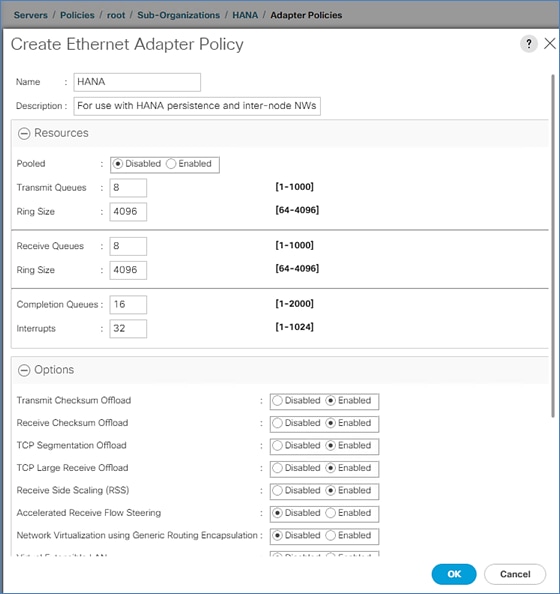
7. Click OK to create the Ethernet Adapter policy.
Persistent Memory Policy
A persistent memory policy allows the configuration on how persistent memory modules are used. It contains goals and namespaces. In this reference design we use host tools to configure the persistent memory and leave this policy blank.
Network Configuration
The core network requirements for SAP HANA are covered by Cisco UCS defaults. Cisco UCS is based on 40-GbE network connection and provides redundancy via the Dual Fabric concept. The Service Profile is configured to distribute the traffic across Fabric Interconnect A and B. During normal operation, the traffic in the Internal Zone and the database NFS data traffic is on FI A and all the other traffic (Client Zone and Database NFS log) is on FI B. The inter-node traffic flows from a blade server to the Fabric Interconnect A and back to the other blade server. All the other traffic must go over the Cisco MDS switches to storage or to the data center network. With the integrated algorithms for bandwidth allocation and quality of service the Cisco UCS and Cisco Nexus distributes the traffic in an efficient way.
Network Control Policy to Enable CDP
CDP needs to be enabled to learn the MAC address of the End Point. To update default Network Control Policy, follow these steps:
1. In the Navigation pane, click LAN.
2. Select LAN > Policies > root > Network Control Policies > default.
3. In the right pane, click the General tab.
4. For CDP, select Enabled.
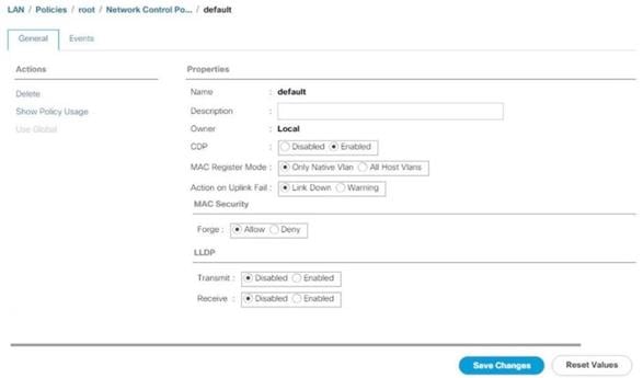
5. Click Save Changes.
6. Click OK.
Set Jumbo Frames in Cisco UCS Fabric
The core network requirements for SAP HANA are covered by Cisco UCS defaults. Cisco UCS is based on 40GbE and provides redundancy through the Dual Fabric concept. The Service Profile is configured to distribute the traffic across Fabric Interconnect A and B.
To configure jumbo frames and enable quality of service in the Cisco UCS fabric, follow these steps:
1. In the Navigation pane, click LAN.
2. Select LAN > LAN Cloud > QoS System Class.
3. In the right pane, click the General tab.
4. On the MTU Column, enter 9216 in the box.
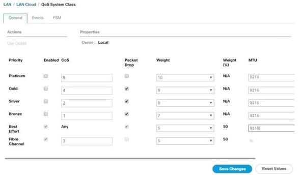
5. Click Save Changes.
6. Click Yes to accept the QoS Change Warning.
7. Click OK.
Create LAN Uplink Port Channels
Configure the LAN uplinks from FI-A and FI-B towards northbound Nexus switches, in port-channel, for use by all network zones as prescribed by SAP. For example, we create port-channel 21 on FI-A and port-channel 22 on FI- B. This port channel pair will have corresponding vPCs defined on N9Ks that ensures seamless redundancy and failover for the north-south network traffic
It would suffice to have a port-channel pair on FI with corresponding vPC pair on N9Ks to handle traffic of all network zones provided we have enough ports to account for the desired bandwidth. In this reference architecture, we use two pairs of 2 x 40GE ports for the FI<->N9K connectivity for port-channels. It is possible to add more based on the requirements or use-cases.
Create the port channel pair 21 and 22 with two 40GE ports from FIs to the Nexus switches to cater to the SAP HANA’s Client, Admin and Internal network zones.
Create another port channel pair 31 and 32 with two 40GE ports from FIs to the Nexus switches that could exclusively handle bandwidth intensive SAP HANA Storage zone traffic comprising of HANA node backup network.
To create and configure two port channels, one each from FI-A/FI-B to the uplink Cisco Nexus switches, follow these steps:
1. In the Navigation pane, click LAN.
2. Select LAN > LAN Cloud > Fabric A and expand the Fabric A tree.
3. Right-click Port Channels and select Create Port Channel.
4. Enter 21 as the unique ID of the port channel.
5. Enter Uplink-to-N9K as the name of the port channel.
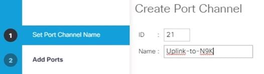
6. Click Next.
7. Select the following ports to be added to the port channel:
- Slot ID 1 and port 33
- Slot ID 1 and port 34
![]() The ports are selected based on Uplink Port connectivity and are specific to this sample configuration.
The ports are selected based on Uplink Port connectivity and are specific to this sample configuration.
8. Click >> to add the ports to the port channel.
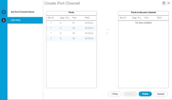
9. Click Finish to create the port channel.
10. Click OK.
11. Select LAN > LAN Cloud > Fabric B and expand the Fabric B tree.
12. Right-click Port Channels and select Create Port Channel.
13. Enter 22 as the unique ID of the port channel.
14. Enter Uplink-to-N9K as the name of the port channel.
15. Click Next.
16. Select the following ports to be added to the port channel:
- Slot ID 1 and port 33
- Slot ID 1 and port 34
17. Click >> to add the ports to the port channel.
18. Click Finish to create the port channel.
19. Click OK.
![]() Configure a second set of port-channels from FI-A and FI-B to the nexus switches. This uplink port-channel could be exclusively used for backup network traffic.
Configure a second set of port-channels from FI-A and FI-B to the nexus switches. This uplink port-channel could be exclusively used for backup network traffic.
20. In the Navigation pane, click LAN.
21. Select LAN > LAN Cloud > Fabric A and expand the Fabric A tree.
22. Right-click Port Channels and select Create Port Channel.
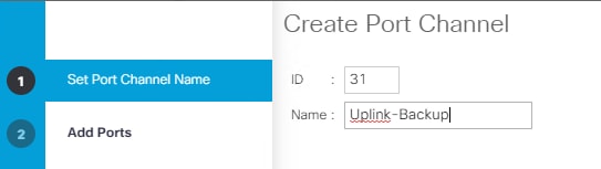
23. Enter 31 as the unique ID of the port channel.
24. Enter Uplink-Backup as the name of the port channel.
25. Click Next.
26. Select the following ports to be added to the port channel:
- Slot ID 1 and port 31
- Slot ID 1 and port 32
![]() The ports are selected based on Uplink Port connectivity and are specific to this sample configuration.
The ports are selected based on Uplink Port connectivity and are specific to this sample configuration.
27. Click >> to add the ports to the port channel.
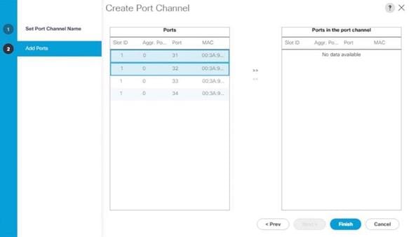
28. Click Finish to create the port channel.
29. Click OK.
30. Select LAN > LAN Cloud > Fabric B and expand the Fabric B tree.
31. Right-click Port Channels and select Create Port Channel.
32. Enter 31 as the unique ID of the port channel.
33. Enter Uplink-Backup as the name of the port channel.
34. Click Next.
35. Select the following ports to be added to the port channel:
- Slot ID 1 and port 31
- Slot ID 1 and port 32
36. Click >> to add the ports to the port channel.
37. Click Finish to create the port channel.
38. Click OK.
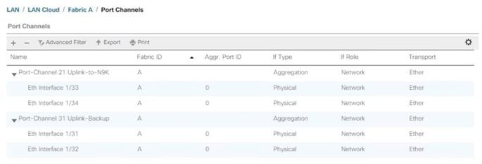
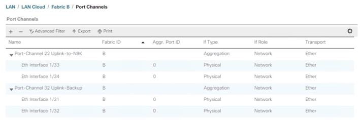
VLAN Configurations
Within Cisco UCS, all network types for the SAP HANA systems are manifested by defined VLANs. Even though six VLANs are defined in this reference architecture, VLANs for all the networks are not necessary if the solution will not use those networks. For example, if the Replication Network is not used in the solution, then VLAN ID 225 does not need not be created.
The VLAN IDs can be changed if required to match the VLAN IDs in the customer’s network – for example, ID 221 for backup should match the configured VLAN ID at the customer uplink network switches.
![]() In this procedure, six VLANs are created for SAP HANA Scale-Up configurations and eight VLANs are created for SAP HANA Scale-Out configurations.
In this procedure, six VLANs are created for SAP HANA Scale-Up configurations and eight VLANs are created for SAP HANA Scale-Out configurations.
Create VLANs
To configure the necessary VLANs for the Cisco UCS environment, follow these steps:
1. In the Navigation pane, click LAN.
2. Select LAN > LAN Cloud > VLANs.
3. Right-click VLANs and select Create VLANs.
4. For the management network enter HANA-Mgmt as VLAN name.
5. Keep the Common/Global option selected for the scope of the VLAN.
6. Enter <var_mgmt_vlan_id> as VLAN ID of the management network.
7. Keep Sharing Type as None.
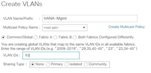
8. Click OK and then click OK again.
9. Repeat steps 1-8 for each VLAN to be created. See Figures 11 to 17 for the settings.
10. Create VLAN for HANA-Backup.
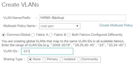
11. Create VLAN for HANA-Client.
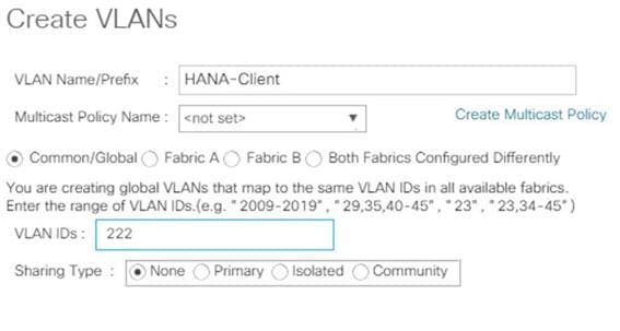
12. Create HANA AppServer VLAN.
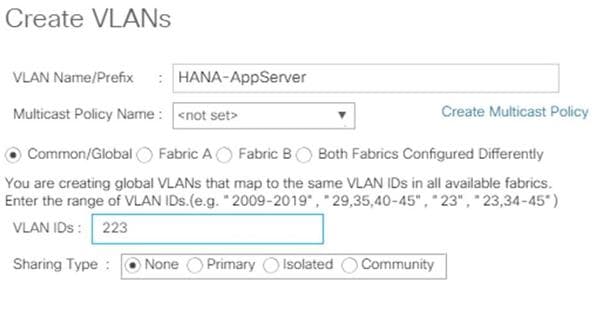
13. Create HANA DataSource VLAN.
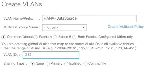
14. Create HANA Replication VLAN.
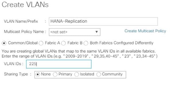
![]() SAP HANA Scale-Out deployments require two additional VLANs for the host-to-host communication and the shared NFS access to the volume /hana/shared.
SAP HANA Scale-Out deployments require two additional VLANs for the host-to-host communication and the shared NFS access to the volume /hana/shared.
15. Create VLAN for SAP HANA host-to-host communication (SAP HANA Scale-Out).
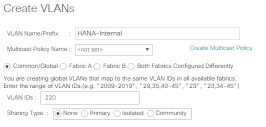
16. Create HANA NFSShared VLAN (SAP HANA Scale-Out).
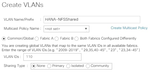
The overview of all previously created VLANs is shown below.
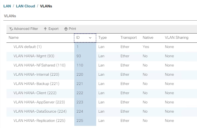
Create VLAN Groups
For easier management and bandwidth allocation to a dedicated uplink on the Fabric Interconnect, VLAN Groups are created within Cisco UCS. SAP groups the networks recommended for a HANA system into the following zones which could be translated to VLAN groups in Cisco UCS configuration:
· Client Zone – including AppServer, Client and DataSource networks
· Internal Zone – including Inter-node and System Replication networks
· Storage Zone – including Backup and IP storage networks
· And optional Admin zone – including Management or OS cluster network, if any
![]() This architecture reference consists of three VLAN Groups. Based on the solution requirements additional VLAN groups might be required depending on the implementation scenario.
This architecture reference consists of three VLAN Groups. Based on the solution requirements additional VLAN groups might be required depending on the implementation scenario.
To configure the necessary VLAN Groups for the Cisco UCS environment, follow these steps:
1. In the Navigation pane, click LAN.
2. Select LAN > LAN Cloud > VLAN Groups.
3. Right-click VLAN Groups and select Create VLAN Groups.
4. Enter Admin-Zone as VLAN Group name used for the Infrastructure network.
5. Select the HANA-Mgmt VLAN.
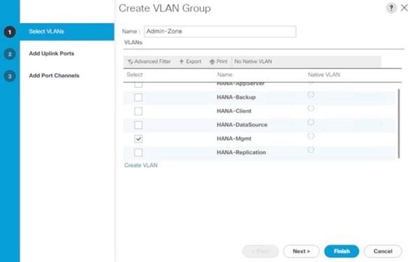
6. Click Next
7. Click Next on Add Uplink Ports, since you will use port-channel.
8. Choose port-channels 21 and 22 created earlier for the uplink network and click >>.
9. Click Finish.
10. Create the Client Zone VLAN Group. Select HANA-AppServer, HANA-Client and HANA-DataSource networks to be part of this VLAN group.
11. Select LAN > LAN Cloud > VLAN Groups.
12. Right-click VLAN Groups and select Create VLAN Groups.
13. Enter Client-Zone as VLAN Group name used for the client network.
14. Select the HANA-AppServer, HANA-Client and HANA-DataSource VLANs.
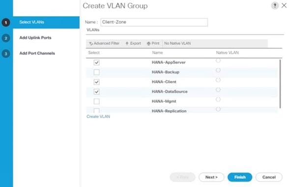
15. Click Next.
16. Click Next on Add Uplink Ports, since you will use port-channel.
17. Choose port-channels 21 and 22 created earlier for the uplink network and click >>.
18. Click Finish.
19. Create the Backup Network VLAN Group. Select the HANA-Backup network and port channels 31 and 32.
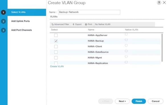
20. For SAP HANA Scale-Out installations create the Internal Network VLAN Group. Select HANA-internal and port channels 21 and 22.

21. For SAP HANA Scale-Out installations create the Storage VLAN Group. Select the HANA-NFSShared VLAN and port channels 31 and 32.
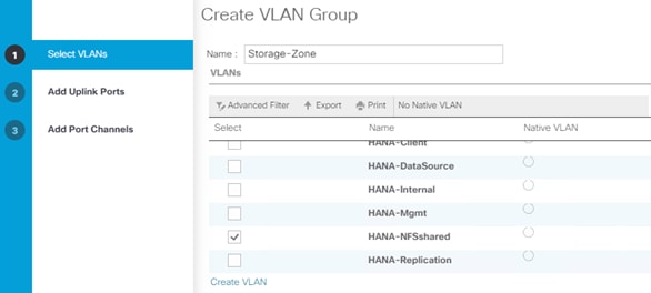
![]() Depending on your requirements, additional VLAN groups can be created following the above steps.
Depending on your requirements, additional VLAN groups can be created following the above steps.
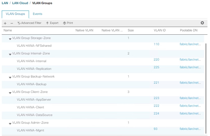
![]() For each VLAN Group a dedicated Ethernet Uplink Port or Port Channel can be selected, if the use-case demands. Alternatively, a single uplink Port Channel with more ports to enhance the bandwidth could also be used if that suffices.
For each VLAN Group a dedicated Ethernet Uplink Port or Port Channel can be selected, if the use-case demands. Alternatively, a single uplink Port Channel with more ports to enhance the bandwidth could also be used if that suffices.
Create vNIC Template
Each VLAN is mapped to a vNIC template to specify the characteristic of a specific network. The vNIC template configuration settings include MTU size, Failover capabilities and MAC-Address pools.
To create vNIC templates for the Cisco UCS environment, follow these steps:
1. In the Navigation pane, click LAN.
2. Select Policies > root > Sub-Organization > T01-HANA > vNIC Templates.
3. Right-click vNIC Templates and select Create vNIC Template.
4. Use HANA-Mgmt as vNIC template name.
5. For Fabric ID select Fabric A and check mark Enable Failover.
6. Under Target, ensure the VM checkbox is unchecked.
7. Select Updating Template as the Template Type.
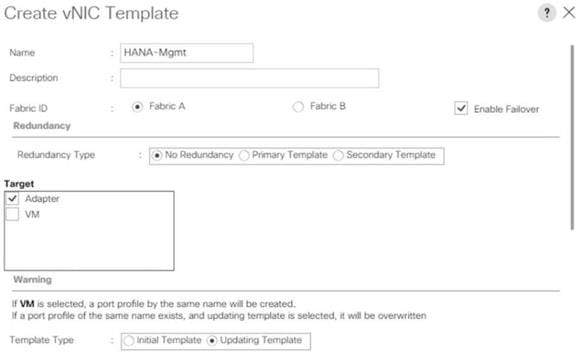
8. In the VLANs tab, select the checkbox for HANA-Mgmt and the radio button for native VLAN.
9. For MTU, enter 9000.
10. In the MAC Pool list, select FI-A.
11. For Network Control Policy Select default from drop-down list.
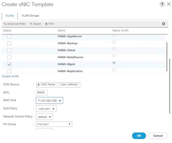
12. Click OK to create the vNIC template.
13. Click OK.
![]() For most SAP HANA use cases the network traffic is well distributed across the two Fabrics (Fabric A and Fabric B) using the default setup. In special cases, it can be required to rebalance this distribution for better overall performance. This can be done in the vNIC template with the Fabric ID setting. The MTU settings must match the configuration in customer data center. MTU setting of 9000 is recommended for best performance.
For most SAP HANA use cases the network traffic is well distributed across the two Fabrics (Fabric A and Fabric B) using the default setup. In special cases, it can be required to rebalance this distribution for better overall performance. This can be done in the vNIC template with the Fabric ID setting. The MTU settings must match the configuration in customer data center. MTU setting of 9000 is recommended for best performance.
Create a Separate vNIC Template for Each Network
To create a vNIC template for a client network, follow these steps:
1. Select Policies > root > Sub-Organization > T01-HANA > vNIC Templates.
2. Right-click vNIC Templates and select Create vNIC Template.
3. Use HANA-Client as vNIC template name.
4. For Fabric ID select Fabric B and check mark Enable Failover.
5. Under Target, make sure that the VM checkbox is unchecked.
6. Select Updating Template as the Template Type.
7. In the VLANs tab, select the check box for HANA-Client and the radio button for native VLAN.
8. For MTU, enter 9000.
9. In the MAC Pool list, select FI-B
10. For Network Control Policy Select default from drop-down list.
11. Click OK to create the vNIC template.
Create a vNIC Template for Application Server Network
To create a vNIC template for the application server network, follow these steps:
1. Select Policies > root > Sub-Organization > T01-HANA > vNIC Templates.
2. Right-click vNIC Templates and select Create vNIC Template.
3. Enter HANA-AppServer as the vNIC template name.
4. For Fabric ID select Fabric A and check mark Enable Failover.
5. Under Target, make sure that the VM checkbox is unchecked.
6. Select Updating Template as the Template Type.
7. In the VLANs tab, select the check box for HANA-AppServer and the radio button for native VLAN.
8. For MTU, enter 9000.
9. In the MAC Pool list, select FI-A
10. For Network Control Policy Select default from drop-down list.
11. Click OK to create the vNIC template.
Create a vNIC Template for DataSource Network
To create a vNIC template for the DataSource network, follow these steps:
1. Select Policies > root > Sub-Organization > T01-HANA > vNIC Templates.
2. Right-click vNIC Templates and select Create vNIC Template.
3. Enter HANA-DataSource as the vNIC template name.
4. For Fabric ID select Fabric A and check mark Enable Failover.
5. Under Target, make sure that the VM checkbox is unchecked.
6. Select Updating Template as the Template Type.
7. In the VLANs tab, select the check box for HANA-DataSource and the radio button for native VLAN.
8. Set HANA-DataSource as the native VLAN.
9. For MTU, enter 9000.
10. In the MAC Pool list, select FI-A
11. For Network Control Policy Select default from drop-down list.
12. Click OK to create the vNIC template.
Create a vNIC Template for Replication Network
To create a vNIC template for the replication network, follow these steps:
1. Select Policies > root > Sub-Organization > T01-HANA > vNIC Templates.
2. Right-click vNIC Templates and select Create vNIC Template.
3. Enter HANA-Replication as the vNIC template name.
4. For Fabric ID select Fabric B and check mark Enable Failover.
5. Under Target, make sure that the VM checkbox is unchecked.
6. Select Updating Template as the Template Type.
7. In the VLANs tab, select the check box for HANA-Replication and the radio button for native VLAN.
8. For MTU, enter 9000.
9. In the MAC Pool list, select FI-B.
10. For Network Control Policy Select default from drop-down list.
11. Click OK to create the vNIC template.
Create a vNIC Template for Backup Network
To create a vNIC template for the backup network, follow these steps:
1. Select Policies > root > Sub-Organization > T01-HANA > vNIC Templates.
2. Right-click vNIC Templates and select Create vNIC Template.
3. Enter HANA-Backup as the vNIC template name.
4. For Fabric ID select Fabric B and check mark Enable Failover.
5. Under Target, make sure that the VM checkbox is unchecked.
6. Select Updating Template as the Template Type.
7. In the VLANs tab, select the check box for HANA-Backup and the radio button for native VLAN.
8. For MTU, enter 9000.
9. In the MAC Pool list, select FI-B.
10. For Network Control Policy Select default from drop-down list.
11. Click OK to create the vNIC template.
Create a vNIC Template for Internal Network
To create a vNIC template for the backup network, follow these steps:
1. Select Policies > root > Sub-Organization > T01-HANA > vNIC Templates.
2. Right-click vNIC Templates and select Create vNIC Template.
3. Enter HANA-Internal as the vNIC template name.
4. For Fabric ID select Fabric B and check mark Enable Failover.
5. Under Target, make sure that the VM checkbox is unchecked.
6. Select Updating Template as the Template Type.
7. In the VLANs tab, select the check box for HANA-Internal and the radio button for native VLAN.
8. For MTU, enter 9000.
9. In the MAC Pool list, select FI-B.
10. For Network Control Policy Select default from drop-down list.
11. Click OK to create the vNIC template.
Create a vNIC Template for Storage Network
To create a vNIC template for the backup network, follow these steps:
1. Select Policies > root > Sub-Organization > T01-HANA > vNIC Templates.
2. Right-click vNIC Templates and select Create vNIC Template.
3. Enter HANA-NFSShared as the vNIC template name.
4. For Fabric ID select Fabric B and check mark Enable Failover.
5. Under Target, make sure that the VM checkbox is unchecked.
6. Select Updating Template as the Template Type.
7. In the VLANs tab, select the check box for HANA-Backup and the radio button for native VLAN.
8. For MTU, enter 9000.
9. In the MAC Pool list, select FI-B.
10. For Network Control Policy Select default from drop-down list.
11. Click OK to create the vNIC template.
The figure below shows the list of vNIC Templates created for SAP HANA.
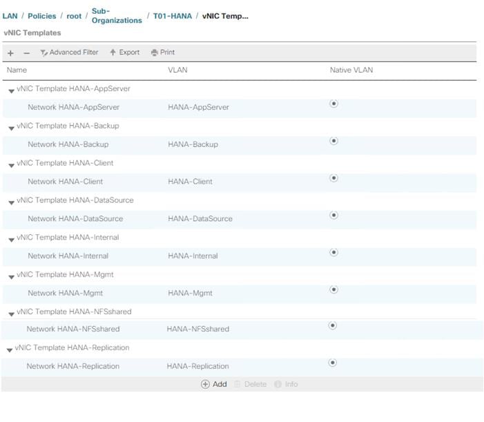
(Optional) Create LAN Connectivity Policy
A LAN Connectivity Policy in the target organization (T01-HANA) force the device ordering through Consistent Device Naming (CDN). The policy avoids manual reordering of ethernet devices during the Linux installation. An alternative configuration is to specify the vNIC and vHBA placement manually in the process of creating the service profile template. The manual placement will be described when creating the service profile template.
SAP HANA Scale-Up
To create a LAN Connectivity Policy, follow these steps:
1. In the Navigation pane, click LAN.
2. Select LAN > Policies > root > Sub-Organizations > T01-HANA > LAN Connectivity Policies.
3. Right-click LAN Connectivity Policies and select Create LAN Connectivity Policy.
4. Use FC-LAN-ScaleUp as policy name.
5. (Optional) provide a policy description.
6. Click the Add button to add a vNIC.
7. In the Create vNIC dialog box, use HANA-Mgmt as vNIC name.
8. Check mark the use vNIC Template box.
9. In the vNIC Template dropdown menu, select HANA-Mgmt.
10. Set the Adapter Policy to Linux.
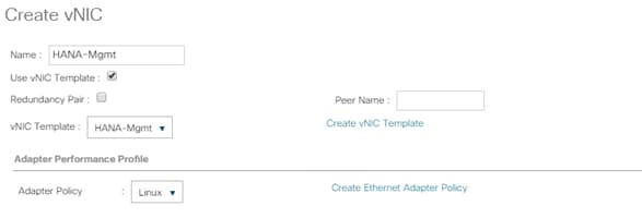
11. Click OK to add this vNIC to the policy.
12. Click Add to add another vNIC.
13. Click OK to create the LAN Connectivity Policy and confirm with OK again.
The following figure displays the overview of all previously created VLANs:
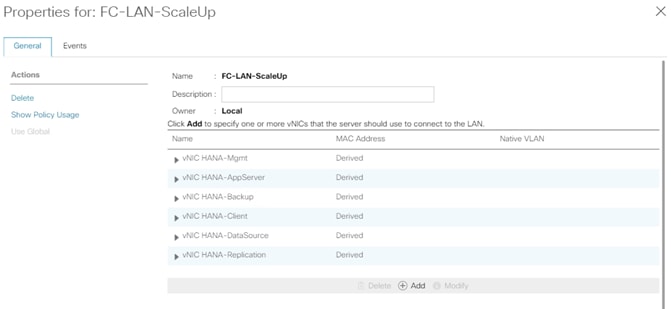
SAP HANA Scale-Out
To create a LAN Connectivity Policy, follow these steps:
1. In the Navigation pane, click LAN.
2. Select LAN > Policies > root > Sub-Organizations > T01-HANA > LAN Connectivity Policies.
3. Right-click LAN Connectivity Policies and select Create LAN Connectivity Policy.
4. Use FC-LAN-ScaleOut as policy name.
5. (Optional) Provide a policy description.
![]() Create all entries like in the FC-LAN-Policy for the SAP HANA Scale-Up.
Create all entries like in the FC-LAN-Policy for the SAP HANA Scale-Up.
6. Click Add to add a vNIC.
7. In the Create vNIC dialog box, use HANA-Internal as vNIC name.
8. Check mark the use vNIC Template box.
9. In the vNIC Template drop-down list, select HANA-Internal.
10. Set the Adapter Policy to HANA.
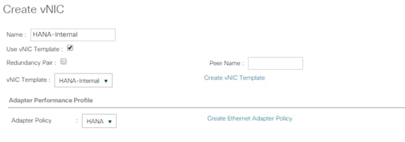
11. Click OK to add this vNIC to the policy.
12. Click Add to add another vNIC.
13. In the Create vNIC dialog box, use HANA-NFSShared as vNIC name.
14. Check mark the use vNIC Template box.
15. In the vNIC Template dropdown menu, select HANA-Internal.
16. Set the Adapter Policy to HANA.
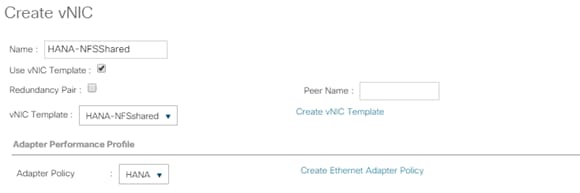
17. Click OK to create the LAN Connectivity Policy and confirm with OK again.
The overview of all previously created VLANs is shown in the following figure:
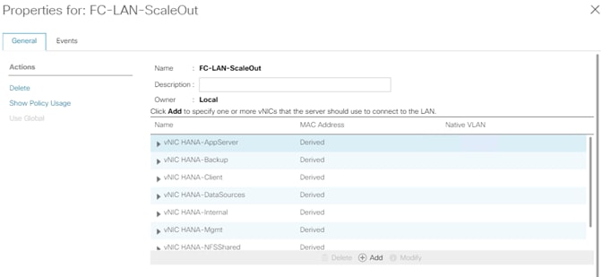
Cisco UCS SAN Configuration
Create FC Port Channels
Create a port channel on FIs A and B for the uplink FC interfaces connecting to the respective Cisco MDS Fabric switches which will be used by the specific VSANs we created earlier on the Cisco MDS. This port channel pair will have corresponding F-port-channel-trunks defined on the Cisco MDS switches that allows the fabric logins from NPV enabled FIs to be virtualized over the port channel. This provides non-disruptive redundancy should individual member links fail.
To configure the two port channels, one from FI-A as well as FI-B to both Cisco Nexus switches, follow these steps:
1. In the Navigation pane, click SAN.
2. Under SAN > SAN Cloud > Fabric A, expand the Fabric A tree.
3. Right-click FC Port Channels and select Create FC Port Channel.
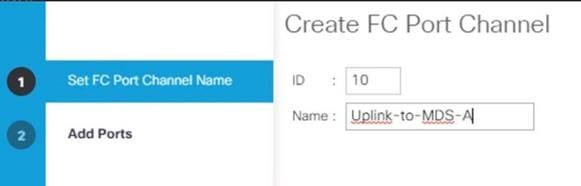
4. Enter the unique ID number10 for the port channel.
5. Use Uplink-to-MDS-A as Port Channel Name.
6. Click Next.
7. Set Port Channel Admin Speed to 16gbps. Select the following ports to be added to the port channel:
- Slot ID 1 and port 1
- Slot ID 1 and port 2
- Slot ID 1 and port 3
- Slot ID 1 and port 4
![]() The ports are selected based on Uplink Port connectivity and hence very specific to this sample configuration.
The ports are selected based on Uplink Port connectivity and hence very specific to this sample configuration.
8. Click >> to add the ports to the port channel.
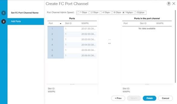
9. Click Finish to create the port channel.
10. Click OK.
11. In the navigation pane, under SAN > SAN Cloud – Fabric B, expand the Fabric B tree.
12. Right-click FC Port Channels and select Create FC Port Channel.
13. Enter the unique ID number20 for the port channel.
14. Use Uplink-to-MDS-B as Port Channel Name.
15. Click Next.
16. Set Port Channel Admin Speed to 16gbps. Select the following ports to be added to the port channel:
- Slot ID 1 and port 1
- Slot ID 1 and port 2
- Slot ID 1 and port 3
- Slot ID 1 and port 4
17. Click >> to add the ports to the port channel.
18. Click Finish to create the port channel.
19. Click OK.
Create VSANs
Two VSANs, one each for Fabric A and Fabric B, are required for this Cisco UCS environment. To create them follow these steps:
1. In the Navigation pane, click SAN.
2. Select SAN > SAN Cloud > VSANs.
3. Right-click VSANs and select Create VSAN.
4. Use Fab-A as the VSAN name for Fabric A.
5. Retain ‘Disabled’ for FC Zoning option and select Fabric A.
6. Enter <var_fabric-A_vsan_id> as VSAN ID. Use the same value as FCOE VLAN ID.
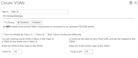
7. Click OK and then click OK again.
8. Select SAN > SAN Cloud > VSANs.
9. Right-click VSANs and select Create VSAN.
10. Use Fab-B as the VSAN name for Fabric B.
11. Retain ‘Disabled’ for FC Zoning option and select Fabric B.
12. Enter <var_fabric-B_vsan_id> as VSAN ID. Use the same value as FCOE VLAN ID.
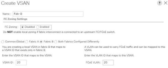
13. Click OK and then click OK again.
Assign Respective Fabric FC Channels to Created VSAN
To assign the FC port channels to the fabric VSANs just created, follow these steps:
1. In the Navigation pane, click SAN.
2. Select SAN > SAN Cloud > Fabric A > FC Port Channels.
3. Select the configured FC Port Channel (FC Port-Channel 10 Uplink-to-MDS-A).
4. In the General tab, change the VSAN property from default (1) to Fab-A VSAN 10 created for Fabric-A.
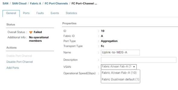
5. Select Save changes. Click OK. After the settings are saved, the Port Channel status changes to Up.
6. Select SAN > SAN Cloud > Fabric B > FC Port Channels.
7. Select the configured FC Port Channel (FC Port-Channel 20 Uplink-to-MDS-B).
8. On the right pane in the General tab, change the VSAN property from default (1) to Fab-B VSAN 20 created for Fabric-B.
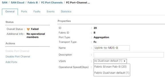
9. Select Save changes. Click OK. After the settings are saved, the Port Channel status changes to Up.
Create vHBA Template
To create two vHBA templates, one each for Fabric A and Fabric B, follow these steps:
1. In the Navigation pane, click SAN.
2. Select SAN > Policies > root > Sub-Organizations > T01-HANA > vHBA Templates.
3. Right-click vHBA Templates and select Create vHBA Template.
4. Use vHBA-A as template name for Fabric A.
5. (Optional) Provide a description.
6. Select Fabric ID A
7. Select VSAN Fab-A
8. Choose as template type the radio button for Updating template.
9. Select WWPN Pool FI-A.
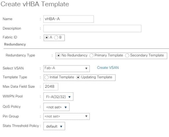
10. Click OK then click OK again.
11. Select SAN > Policies > root > Sub-Organizations > T01-HANA > vHBA Templates.
12. Right-click on vHBA Templates and select Create vHBA Template.
13. Use vHBA-B as template name for Fabric B.
14. Optionally, provide a description.
15. Select Fabric ID B.
16. Select VSAN Fab-B.
17. Choose as template type the radio button for Updating template.
18. Select WWPN Pool as FI-B.
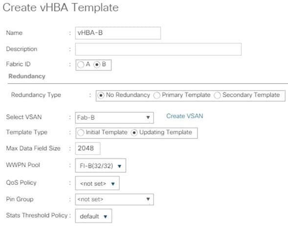
19. Click OK then click OK again.
Create SAN Connectivity Policy
When the physical connectivity is established, the following will configure the zoning for the servers and SAN:
· Storage connection policies: This configures the storage connectivity considering the WWPN Target numbers for the SAN. Since the Zoning is handled by the MDS switches and that FIs aren’t direct attached to the Storage, we do not configure this Storage side connection policy.
· SAN connectivity policies configuration: This configures vHBAs for the servers which will provide WWPN Initiator numbers for the servers. This server-side configuration is needed to prepare the servers for storage connection.
To configure the storage connection policy, follow these steps:
1. In the Navigation pane, click SAN.
2. Select Policies > root > Sub-Organizations > HANA > SAN Connectivity Policies.
3. Right-click SAN Connectivity Policies and select Create SAN Connectivity Policy.
4. Provide name as HANA-SAN.
5. (Optional) Add a description.
6. Select HANA-Servers for WWNN Assignment.
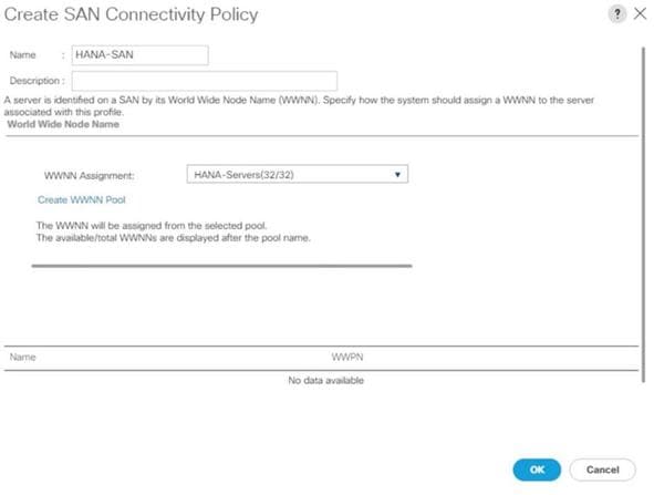
7. Click Add for WWPN to add the vHBAs from the vHBA templates previously created.
8. In the create vHBA window, provide a name as vhba-a and check “Use vHBA Template” option. Select vHBA-A from the vHBA Template drop-down list and Linux for the Adapter Policy. Click OK.
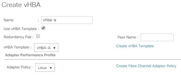
9. Click Add for WWPN to add another vHBA.
10. In the Create vHBA window, provide name as vhba-b and check “Use vHBA Template” option. Select vHBA-B from the vHBA Template drop-down list and Linux for the Adapter Policy.
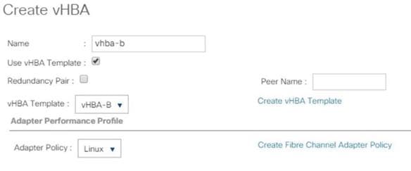
11. Click OK.
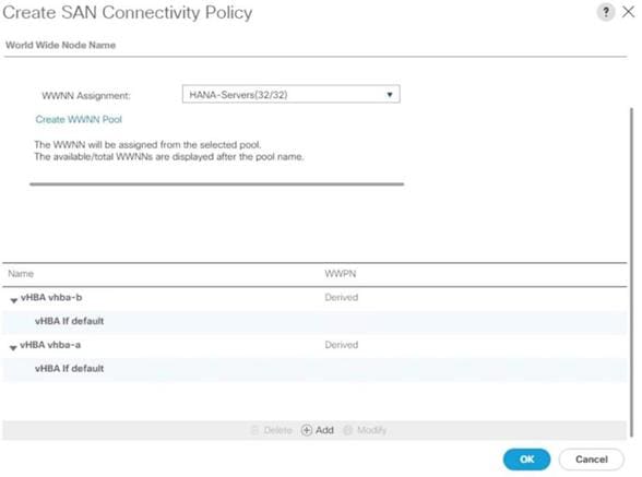
12. Click OK.
Create Boot Policy for SAN Boot
![]() It is strongly recommended to use “Boot from SAN” to realize full benefits of Cisco UCS stateless computing feature such as service profile mobility. The Hitachi VSP storage controller ports are cross connected with the MDS switches so that we have alternate paths to the LUNs, in addition to the built-in redundancy and path management features of the Hitachi VSP storage array itself.
It is strongly recommended to use “Boot from SAN” to realize full benefits of Cisco UCS stateless computing feature such as service profile mobility. The Hitachi VSP storage controller ports are cross connected with the MDS switches so that we have alternate paths to the LUNs, in addition to the built-in redundancy and path management features of the Hitachi VSP storage array itself.
Determine the WWPN information of these storage array target ports from the Hitachi Device Manager.
Configure the SAN primary's primary-target to be port CL1-A and SAN primary's secondary-target to be port CL2-A of the Hitachi VSP Storage. Similarly, the SAN secondary’s primary-target should be port CL3-A and SAN secondary's secondary-target should be port CL4-A
Create a SAN boot policy in the Cisco UCS environment for both host bus adapters hba0 (primary) and hba1 (secondary) by entering the WWPN of the Hitachi Storage FC Ports.
To create a SAN boot policy, follow these steps:
1. In the Navigation tab, click Servers.
2. Select Policies > root > Sub-Organizations > T01-HANA > Boot Policies.
3. Right-click Boot Policies and select Create Boot Policy.
4. Enter HANA-SanBoot as boot policy name.
5. Ensure the “Enforce vNIC/vHBA/iSCSI Name” option is unchecked.
6. (Optional) Checkmark the Boot Security Option to enable UEFI secure boot.
![]() When UEFI secure boot is enabled, the UEFI boot loader, operating system and all drivers must be both signed and able to be authenticated before they can be loaded. The Cisco UCS BIOS firmware includes root certificates from VMWare, Microsoft and Cisco. Other root certificates may be available through the boot loader and/or operating system.
When UEFI secure boot is enabled, the UEFI boot loader, operating system and all drivers must be both signed and able to be authenticated before they can be loaded. The Cisco UCS BIOS firmware includes root certificates from VMWare, Microsoft and Cisco. Other root certificates may be available through the boot loader and/or operating system.
7. Expand the Local Devices drop-down menu and Choose Add CD-ROM.
8. Expand the vHBAs drop-down list and Choose Add SAN Boot. In the Add SAN Boot dialog box, select type as ‘Primary’ and enter "hba0" in the vHBA field and click OK.
9. From the vHBAs drop-down list choose “Add SAN Boot Target.”
10. Keep 0 as the value for Boot Target LUN. Enter the WWPN for FC port CL1-A of Hitachi VSP Storage and click OK.
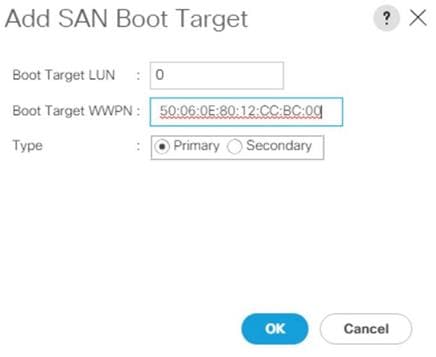
11. From the vHBAs drop-down list choose “Add SAN Boot Target” To add a secondary SAN Boot target for hba0.
12. Enter boot target LUN as 0 and WWPN for FC port CL2-A of Hitachi VSP Storage. Click OK.
13. From the vHBAs drop-down list and Choose Add SAN Boot. In the Add SAN Boot dialog box, enter "hba1" in the vHBA field. Click OK.
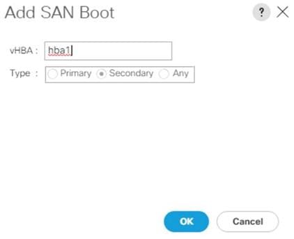
14. From the vHBAs drop-down list choose “Add SAN Boot Target.”
15. Keep 0 as the value for Boot Target LUN. Enter the WWPN for FC port CL2-A of Hitachi VSP Storage and add click OK.
16. From the vHBAs drop-down list choose “Add SAN Boot Target” to add a secondary SAN Boot target into hba1.
17. Enter boot target LUN as 0 and WWPN for FC port CL4-A of Hitachi VSP Storage. Click OK.
18. Click OK and confirm the Create Boot Policy pop-up with OK.
19. After creating the FC boot policies, you can view the boot order in the Cisco UCS Manager GUI. To view the boot order, navigate to Servers > Policies > root > Sub-Organizations > T01-HANA > Boot Policies> HANA-SanBoot to view the boot order of the Cisco UCS Manager as shown below.
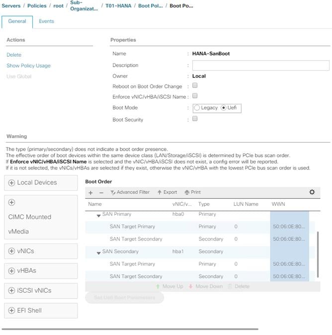
Create Service Profile Templates for SAP HANA Servers
The LAN, SAN configurations and relevant SAP HANA policies must be defined prior to creating a Service Profile Template. The following procedure will highlight, when the service profile template deviate between the SAP HANA Scale-Up and SAP HANA Scale-Out configuration.
To create the service profile template, follow these steps:
1. In the Navigation pane, click Servers.
2. Select Service Profile Templates > root > Sub-Organization > T01-HANA.
3. Right-click T01-HANA and select Create Service Profile Template.
The “Create Service Profile Template” wizard displays.
4. Enter HANA-ScaleUp (or HANA-Scale-Out) as service profile template name.
5. Select the template type option “Updating Template”.
6. Under UUID, select HANA-UUID as the UUID pool. Optionally add a description.
7. Click Next.
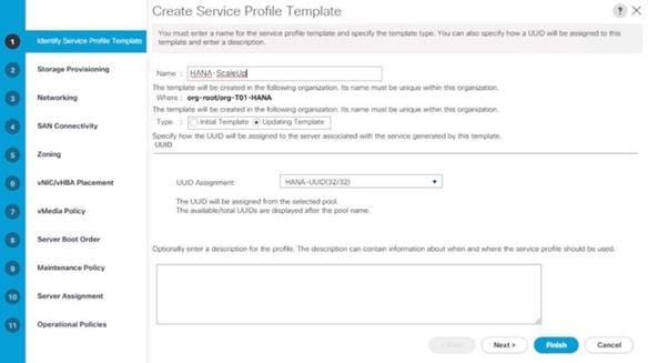
8. In the Storage Provisioning area, nothing needs to be configured. Click Next.
9. In the Networking area keep the default settings for Dynamic vNIC Connection Policy.
10. Select the Expert radio button for the ‘How would you like to configure LAN connectivity’ question.
a. Click Add to add a vNIC to the template.
b. In the Create vNIC dialog box, enter HANA-AppServer as the name of the vNIC.
c. Check the Use vNIC Template checkbox.
d. In the vNIC Template drop-down list, select HANA-AppServer.
e. Set the Adapter Policy to Linux.
f. Click OK to add this vNIC to the template.
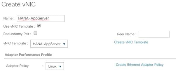
11. Repeat step 11 for each vNIC. Refer to figure 25 to 31 for details.
12. Add vNIC for HANA-Backup.
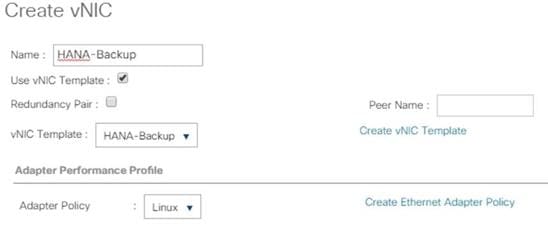
13. Add vNIC for HANA-Client.
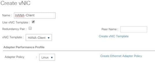
14. Add vNIC for HANA-DataSource.
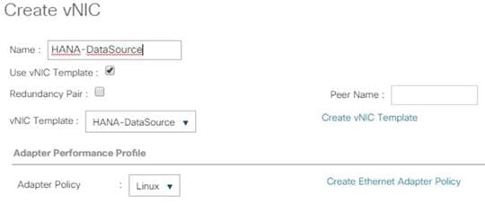
15. Add vNIC for HANA-Mgmt.
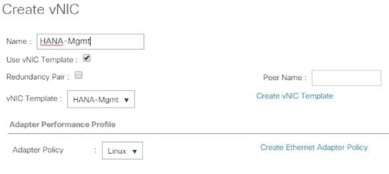
16. Add vNIC for HANA-Replication.
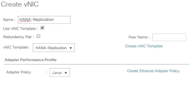
17. For the HANA Scale-Out service profile template add vNIC for HANA-Internal and select the adapter policy HANA.
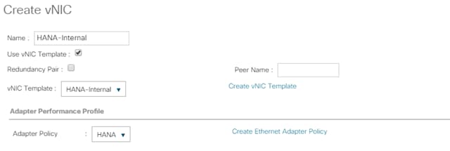
18. For the HANA Scale-Out service profile template add vNIC for NFS Shared and select the adapter policy HANA.
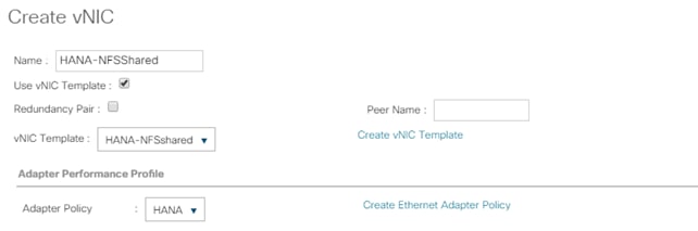
19. Review the table in the Networking pane to make sure that all vNICs were created.
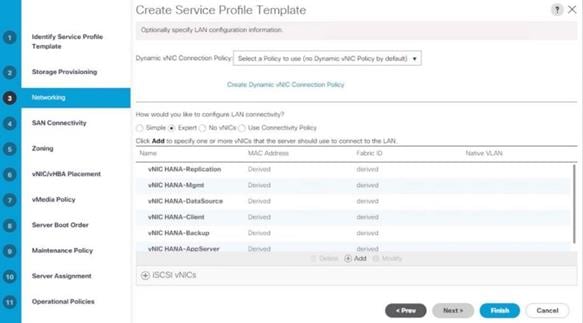
20. Click Next.
21. Configure the SAN Connectivity:
a. Select the ‘Use Connectivity Policy’ radio button to answer “How would you like to configure SAN connectivity?”.
b. Select HANA-SAN for SAN Connectivity Policy. Click Next.
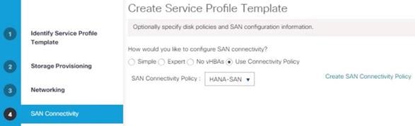
22. Zoning – No changes and click Next.
23. vNIC/vHBA Placement for B480-M5
![]() With the Cisco UCS B480 M5 Blade Server populated with VIC 1340 + Port expander recognized as Adapter1 and VIC 1380 as Adapter 3. Therefore, use vCON 1 and 3 for the vNIC/vHBA assignment to use both adapters.
With the Cisco UCS B480 M5 Blade Server populated with VIC 1340 + Port expander recognized as Adapter1 and VIC 1380 as Adapter 3. Therefore, use vCON 1 and 3 for the vNIC/vHBA assignment to use both adapters.
24. In the Select Placement list, choose Specify Manually.
![]() Instead of a manual placement there is the option to use a LAN connectivity policy instead.
Instead of a manual placement there is the option to use a LAN connectivity policy instead.
25. From the vHBAs tab, assign vhba-a to vCON1.
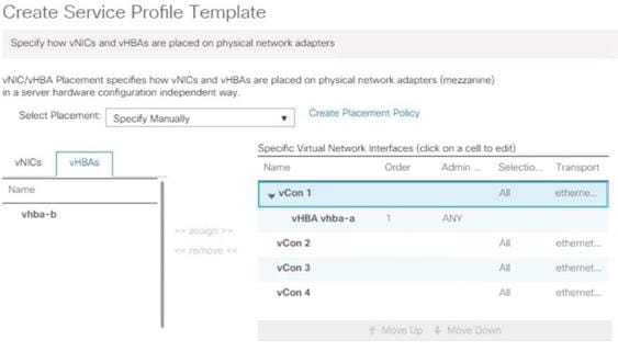
26. From the vNICs tab, choose vCon1 and assign the vNICs to the virtual network interfaces policy in the following order:
a. HANA-Client
b. HANA-AppServer
c. HANA-Replication
d. HANA-Internal (for SAP HANA Scale-Out only)
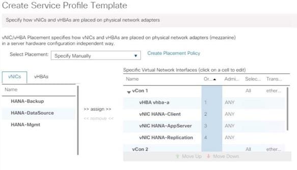
27. Select vCON3. From the vHBAs tab, assign vhba-b to vCON3.
28. Choose vCon3 and assign the vNICs to the virtual network interfaces policy in the following order:
a. HANA-Backup
b. HANA-DataSource
c. HANA-Mgmt
d. HANA-NFSShared (for SAP HANA Scale-Out only)
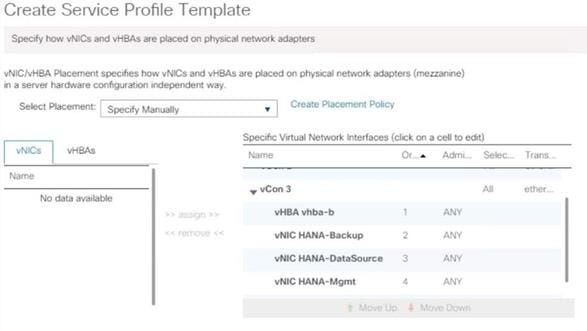
29. Review the table to verify that all vNICs are assigned to the policy in the appropriate order.
30. Click Next.
31. vNIC/vHBA Placement for B200-M5:
![]() With the Cisco UCS B200 M5 Blade Server populated with VIC 1340 + Port expander recognized as Adapter1. Therefore, use vCONs 1 only for the vNIC/vHBA assignment.
With the Cisco UCS B200 M5 Blade Server populated with VIC 1340 + Port expander recognized as Adapter1. Therefore, use vCONs 1 only for the vNIC/vHBA assignment.
a. In the Select Placement list, choose Specify Manually.
b. From the vHBAs tab, assign vhba-a and vbha-b to vCON1
32. From the vNICs tab, choose vCon1 and assign the vNICs to the virtual network interfaces policy in the following order:
a. HANA-Client
b. HANA-AppServer
c. HANA-Replication
d. HANA-Backup
e. HANA-DataSource
f. HANA-Mgmt
33. Review the table to verify that all vNICs are assigned to the policy in the appropriate order.
34. Click Next.
35. No Change required on the vMedia Policy, click Next.
36. Set the server boot order and change the boot policy to “HANA-SanBoot”.
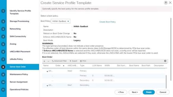
37. Click Next.
38. For Maintenance policy, select the ‘default’ Maintenance Policy. Click Next.
39. For Server Assignment, set pool assignment to ‘assign later’.
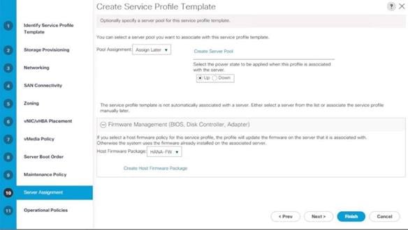
40. Expand Firmware Management and select HANA-FW from the host firmware package list. Click Next.
41. For Operational Policies:
a. BIOS Configuration - In the BIOS Policy list, select HANA-BIOS.
b. External IPMI/Redfish Management Configuration – Select the SoL Configuration Profile SoL-Console.
c. Management IP Address - In the Outband IPv4 tab choose ext-mgmt for the Management IP Address Policy.
d. Power Control Policy Configuration – Select the power control policy HANA.
e. Leave the Scrub policy, KVM Management Policy and Graphics Card Policy with default selections.
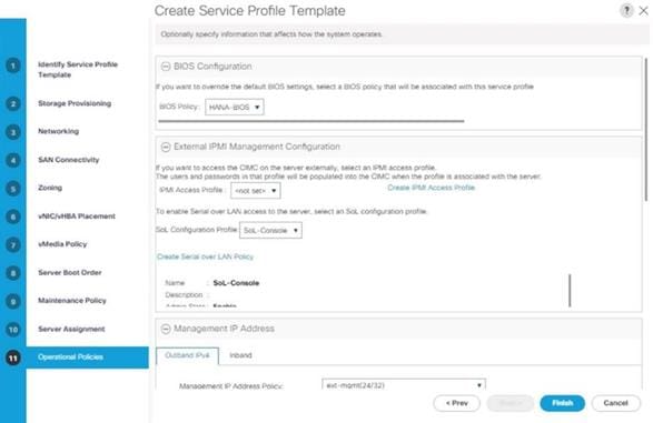
42. Click Finish to create the service profile template.
43. Click OK in the confirmation message.
Create Service Profile from the Template
To create service profiles from the service profile template, follow these steps:
1. In the Navigation pane, click Servers.
2. Select Service Profile Templates > root > Sub-Organization > T01-HANA.
3. Right-click and select Create Service Profiles from Template.
4. Enter HANA-Scale{Up | Out}-0 as the service profile prefix.
5. Enter 1 as Name Suffix Starting Number.
6. Enter 4 as the Number of Instances (we use 4 servers in this example configuration)
7. Select Service Profile Template HANA-Scale{Up | Out}.
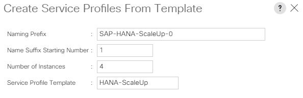
8. Click OK to create the service profile.
Associate Service Profile to Cisco UCS Server
To associate service profile created for a specific server, follow these steps:
1. In the Navigation pane, click Servers.
2. Select Service Profile > root > Sub-Organization > T01-HANA > HANA-Scale(Up | Out)-01.
3. Right-click HANA-Scale{Up | Out}-01 and select Change Service Profile Association.
4. For Server Assignment, select the existing Server from the drop-down list.
5. Click Available Servers.
6. Select the server, as required. Click OK. Click Yes for the Warning. Click OK.
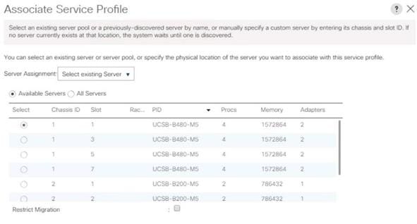
![]() Repeat steps 1-6 to associate each Service Profile with a Server.
Repeat steps 1-6 to associate each Service Profile with a Server.
Configure Cisco MDS 9706 Switches
The MDS configuration implements a common redundant physical fabric design with fabrics represented as “A” and “B”. The validating lab provided a basic MDS fabric supporting VSP Storage Systems that is connected to a Cisco UCS Fabric Interconnect within the SAN environment. Larger deployments may require a multi-tier core-edge or edge-core-edge design with port channels connecting the differing layers of the topology. Further discussion of these kinds of topologies, as well as considerations in implementing more complex SAN environments can be found in this white paper: https://www.cisco.com/c/en/us/products/collateral/storage-networking/mds-9700-series-multilayer-directors/white-paper-c11-729697.pdf
The configuration steps described below are implemented for the Cisco MDS 9706 but are similar to steps required for other Cisco MDS 9000 series switches that may be appropriate for a deployment. When making changes to the design that comply with the compatibility matrices of Cisco and Hitachi, it is required to consult the appropriate configuration documents of the differing equipment to confirm the correct implementation steps.
Physical Connectivity
Physical cabling should be completed by following the diagram and table references in section Physical Cabling.
Cisco MDS Initial Configuration Dialogue
Complete this dialogue on each switch, using a serial connection to the console port of the switch, unless Power on Auto Provisioning is being used.
---- System Admin Account Setup ----
Do you want to enforce secure password standard (yes/no) [y]:
Enter the password for "admin": <var_mds_admin_pw>
Confirm the password for "admin": <var_mds_admin_pw>
---- Basic System Configuration Dialog ----
This setup utility will guide you through the basic configuration of
the system. Setup configures only enough connectivity for management
of the system.
Please register Cisco MDS 9000 Family devices promptly with your
supplier. Failure to register may affect response times for initial
service calls. MDS devices must be registered to receive entitled
support services.
Press Enter at anytime to skip a dialog. Use ctrl-c at anytime
to skip the remaining dialogs.
Would you like to enter the basic configuration dialog (yes/no): yes
Create another login account (yes/no) [n]: <enter>
Configure read-only SNMP community string (yes/no) [n]: <enter>
Configure read-write SNMP community string (yes/no) [n]: <enter>
Enter the switch name : {<var_mds_A_hostname> | <var_mds_B_hostname>}
Continue with Out-of-band (mgmt0) management configuration? (yes/no) [y]: <enter>
Mgmt0 IPv4 address : {<var_mds_A_mgmt_ip> | <var_mds_B_mgmt_ip>}
Mgmt0 IPv4 netmask : <var_oob_mask>
Configure the default gateway? (yes/no) [y]: <enter>
IPv4 address of the default gateway : <var_oob_gateway>
Configure advanced IP options? (yes/no) [n]: <enter>
Enable the ssh service? (yes/no) [y]: <enter>
Type of ssh key you would like to generate (dsa/rsa) [rsa]: <enter>
Number of rsa key bits <1024-2048> [1024]: 2048
Enable the telnet service? (yes/no) [n]: y
Enter the type of drop to configure congestion/no_credit drop? (con/no) [c]: <enter>
Enter milliseconds in multiples of 10 for congestion-drop for logical-type edge
in range (<200-500>/default), where default is 500. [d]: <enter>
Congestion-drop for logical-type core must be greater than or equal to
Congestion-drop for logical-type edge. Hence, Congestion drop for
logical-type core will be set as default.
Enable the http-server? (yes/no) [y]: <enter>
Configure clock? (yes/no) [n]: y
Clock config format [HH:MM:SS Day Mon YYYY] [example: 18:00:00 1 November 2019]: <enter>
Enter clock config :17:18:00 1 November 2019
Configure timezone? (yes/no) [n]: y
Enter timezone config [PST/MST/CST/EST] : CST
Enter Hrs offset from UTC [-23:+23] : <enter>
Enter Minutes offset from UTC [0-59] : <enter>
Configure summertime? (yes/no) [n]: <enter>
Configure the ntp server? (yes/no) [n]: y
NTP server IPv4 address : <var_oob_ntp_ip>
Configure default switchport interface state (shut/noshut) [shut]: noshut
Configure default switchport trunk mode (on/off/auto) [on]: auto
Configure default switchport port mode F (yes/no) [n]: y
Configure default zone policy (permit/deny) [deny]: <enter>
Enable full zoneset distribution? (yes/no) [n]: <enter>
Configure default zone mode (basic/enhanced) [basic]: <enter>
The following configuration will be applied:
password strength-check
switchname {<var_mds_A_hostname> | <var_mds_B_hostname>}
interface mgmt0
ip address {<var_mds_A_mgmt_ip> | <var_mds_B_mgmt_ip>} <var_oob_mask>
no shutdown
ip default-gateway <var_oob_gateway>
ssh key rsa 2048 force
feature ssh
feature telnet
system timeout congestion-drop default logical-type edge
system timeout congestion-drop default logical-type core
feature http-server
clock set 13:51:00 1 November 2019
clock timezone PST 0 0
ntp server <var_oob_ntp_ip>
no system default switchport shutdown
system default switchport trunk mode auto
system default switchport mode F
no system default zone default-zone permit
no system default zone distribute full
no system default zone mode enhanced
Would you like to edit the configuration? (yes/no) [n]: <enter>
Use this configuration and save it? (yes/no) [y]: <enter>
[########################################] 100%
Copy complete.
Configure Fibre Channel Ports and Port Channels
To configure the fibre channel ports and port channels, follow these steps:
1. On MDS 9706 A enter the configuration mode and enable the required features as shown below:
feature fport-channel-trunk
feature npiv
2. Use the following commands to configure the FC Port channel and add all FC ports connected to Cisco UCS Fabric Interconnect A:
int port-channel <var_fc-pc_a_id>
channel mode active
int fc1/1-4
channel-group <var_fc-pc_a_id> force
int port-channel <var_fc-pc_a_id>
switchport mode F
switchport trunk mode off
no shut
3. On MDS 9706 B enter the configuration mode and enable the required features as shown below:
feature fport-channel-trunk
feature npiv
4. Use the following commands to configure the FC Port channel and add all FC ports connected to Cisco UCS Fabric Interconnect B:
int port channel <var_fc-pc_b_id>
channel mode active
int fc1/1-4
channel-group <var_fc-pc_b_id> force
int port channel <var_fc-pc_b_id>
switchport mode F
switchport trunk mode off
no shut
Configure VSANs
To configure VSANs, follow these steps:
1. On MDS 9706 A enter the configuration mode and execute the following commands to configure the VSAN:
vsan database
vsan <var_san_a_id>
vsan <var_san_a_id> interface port-channel <var_fc-pc_a_id>
vsan 10 interface fc 1/13
Traffic on fc1/13 may be impacted. Do you want to continue? (y/n) [n] y
vsan 10 interface fc 1/14
Traffic on fc1/14 may be impacted. Do you want to continue? (y/n) [n] y
vsan 10 interface fc 1/15
Traffic on fc1/15 may be impacted. Do you want to continue? (y/n) [n] y
vsan 10 interface fc 1/16
Traffic on fc1/16 may be impacted. Do you want to continue? (y/n) [n] y
int fc 1/13-16
switchport trunk mode off
switchport trunk allowed vsan <var_san_a_id>
Warning: This command will remove all VSANs currently being trunked and trunk only the specified VSANs.
Do you want to continue? (y/n) [n] y
no shut
2. On MDS 9706 B enter the configuration mode and execute the following commands to configure the VSAN:
vsan database
vsan <var_san_b_id>
vsan <var_san_b_id> interface port-channel <var_fc-pc_b_id>
vsan <var_san_b_id> interface fc 1/13
Traffic on fc1/13 may be impacted. Do you want to continue? (y/n) [n] y
vsan <var_san_b_id> interface fc 1/14
Traffic on fc1/14 may be impacted. Do you want to continue? (y/n) [n] y
vsan <var_san_b_id> interface fc 1/15
Traffic on fc1/15 may be impacted. Do you want to continue? (y/n) [n] y
vsan <var_san_b_id> interface fc 1/16
Traffic on fc1/16 may be impacted. Do you want to continue? (y/n) [n] y
int fc 1/13-16
switchport trunk mode off
switchport trunk allowed vsan <var_san_b_id>
Warning: This command will remove all VSANs currently being trunked and trunk only the specified VSANs.
Do you want to continue? (y/n) [n] y
no shut
![]() Make sure to save the configuration to the startup config using the command “copy running-config startup-config”.
Make sure to save the configuration to the startup config using the command “copy running-config startup-config”.
Create and Configure Fiber Channel Zoning
To create the Fiber Channel connections between the Cisco MDS 9706 switches, the Cisco UCS Fabric Interconnects, and the Hitachi Storage, follow these steps:
1. In the Navigation pane of Cisco UCSM, click Servers.
2. Select Servers > Service Profiles > root > Sub-Organizations >T01-HANA > Service Profile HANA–Scale{Up | Out}-01.
3. On the right-hand pane, click the Storage tab and vHBA's tab to get the WWPN of HBA's as shown in the figure below.
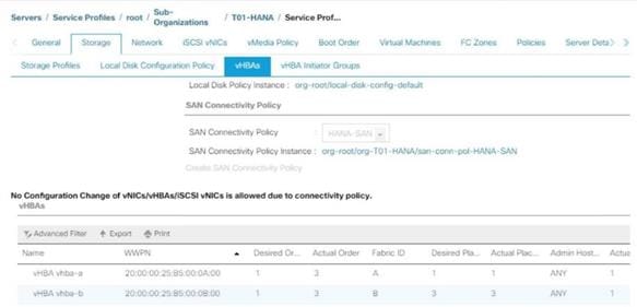
4. Note down the WWPN of the all the configured Servers from their Service Profiles.
In the current example configuration, the WWPN numbers of four server nodes configured are 20:00:00:25:B5:0A:00:00 - 20:00:00:25:B5:0A:00:03 for the Fabric A and 20:00:00:25:B5:0B:00:00 - 20:00:00:25:B5:0B:00:03
5. Connect to the Hitachi Storage Navigator and extract the WWPN of FC Ports connected to the Cisco MDS Switches.
You have connected 8 FC ports from Hitachi Storage to Cisco MDS Switches. FC ports CL1-A, CL1-B, CL2-A, CL2-B are connected to MDS Switch-A and similarly FC ports CL3-A, CL3-B, CL3-A, CL3-B are connected to MDS Switch-B.
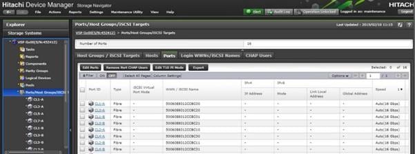
Create Device Aliases for Fibre Channel Zoning
To configure device aliases and zones for the primary boot paths of MDS switch A, follow the steps stated below. In our lab setup we use as naming convention a two-digit server name extension which consist of the chassis and server number in the specific chassis, for example server 1 in chassis 1 translates to server11.
1. Login as admin user and run the following commands.
conf t
device-alias database
device-alias name G370-Cntrl-1-CL1A pwwn 50:06:0e:80:12:cc:bc:00
device-alias name G370-Cntrl-1-CL1B pwwn 50:06:0e:80:12:cc:bc:01
device-alias name G370-Cntrl-1-CL2A pwwn 50:06:0e:80:12:cc:bc:10
device-alias name G370-Cntrl-1-CL2B pwwn 50:06:0e:80:12:cc:bc:11
device-alias name HANA-Server11-hba-a pwwn 20:00:00:25:b5:00:0a:00
device-alias name HANA-Server13-hba-a pwwn 20:00:00:25:b5:00:0a:01
device-alias name HANA-Server15-hba-a pwwn 20:00:00:25:b5:00:0a:02
device-alias name HANA-Server17-hba-a pwwn 20:00:00:25:b5:00:0a:03
exit
device-alias commit
To configure device aliases and zones for the primary boot paths of MDS switch B, follow this step:
1. Login as admin user and run the following commands:
conf t
device-alias database
device-alias name G370-Cntrl-2-CL3A pwwn 50:06:0e:80:12:cc:bc:20
device-alias name G370-Cntrl-2-CL3B pwwn 50:06:0e:80:12:cc:bc:21
device-alias name G370-Cntrl-2-CL4A pwwn 50:06:0e:80:12:cc:bc:30
device-alias name G370-Cntrl-2-CL4B pwwn 50:06:0e:80:12:cc:bc:31
device-alias name HANA-Server11-hba-b pwwn 20:00:00:25:b5:00:0b:00
device-alias name HANA-Server13-hba-b pwwn 20:00:00:25:b5:00:0b:01
device-alias name HANA-Server15-hba-b pwwn 20:00:00:25:b5:00:0b:02
device-alias name HANA-Server17-hba-b pwwn 20:00:00:25:b5:00:0b:03
exit
device-alias commit
Create Zoning
To configure zones for the MDS switch A, follow these steps:
![]() Create a zone for each service profile.
Create a zone for each service profile.
1. Login as admin user and run the following commands:
conf t
zone name HANA-Server11-A vsan 10
member device-alias G370-Cntrl-1-CL1A
member device-alias G370-Cntrl-1-CL1B
member device-alias G370-Cntrl-1-CL2A
member device-alias G370-Cntrl-1-CL2B
member device-alias HANA-Server11-hba-a
exit
zone name HANA-Server13-A vsan 10
member device-alias G370-Cntrl-1-CL1A
member device-alias G370-Cntrl-1-CL1B
member device-alias G370-Cntrl-1-CL2A
member device-alias G370-Cntrl-1-CL2B
member device-alias HANA-Server13-hba-a
exit
zone name HANA-Server15-A vsan 10
member device-alias G370-Cntrl-1-CL1A
member device-alias G370-Cntrl-1-CL1B
member device-alias G370-Cntrl-1-CL2A
member device-alias G370-Cntrl-1-CL2B
member device-alias HANA-Server15-hba-a
exit
zone name HANA-Server17-A vsan 10
member device-alias G370-Cntrl-1-CL1A
member device-alias G370-Cntrl-1-CL1B
member device-alias G370-Cntrl-1-CL2A
member device-alias G370-Cntrl-1-CL2B
member device-alias HANA-Server17-hba-a
exit
2. For SAP HANA Scale-Out deployments add the device alias name for all HANA nodes part of the distributed node installation to each zone to enable failover capabilities:
conf t
zone name HANA-Server21-A vsan 10
member device-alias G370-Cntrl-1-CL1A
member device-alias G370-Cntrl-1-CL1B
member device-alias G370-Cntrl-1-CL2A
member device-alias G370-Cntrl-1-CL2B
member device-alias HANA-Server21-hba-a
member device-alias HANA-Server23-hba-a
member device-alias HANA-Server25-hba-a
exit
zone name HANA-Server23-A vsan 10
member device-alias G370-Cntrl-1-CL1A
member device-alias G370-Cntrl-1-CL1B
member device-alias G370-Cntrl-1-CL2A
member device-alias G370-Cntrl-1-CL2B
member device-alias HANA-Server21-hba-a
member device-alias HANA-Server23-hba-a
member device-alias HANA-Server25-hba-a
exit
zone name HANA-Server25-A vsan 10
member device-alias G370-Cntrl-1-CL1A
member device-alias G370-Cntrl-1-CL1B
member device-alias G370-Cntrl-1-CL2A
member device-alias G370-Cntrl-1-CL2B
member device-alias HANA-Server21-hba-a
member device-alias HANA-Server23-hba-a
member device-alias HANA-Server25-hba-a
exit
3. Create the zone set and add the necessary members:
zoneset name HANA-Servers-A vsan 10
member HANA-Server11-A
member HANA-Server13-A
member HANA-Server15-A
member HANA-Server17-A
member HANA-Server21-A
member HANA-Server23-A
member HANA-Server25-A
exit
4. Activate and save the zone set by running following commands:
zoneset activate name HANA-Servers-A vsan 10
exit
copy run start
To configure zones for the MDS switch B, follow these steps:
![]() Create a zone for each service profile.
Create a zone for each service profile.
1. Login as admin user and run the following commands:
conf t
zone name HANA-Server11-B vsan 20
member device-alias G370-Cntrl-2-CL3A
member device-alias G370-Cntrl-2-CL3B
member device-alias G370-Cntrl-2-CL4A
member device-alias G370-Cntrl-2-CL4B
member device-alias HANA-Server11-hba-b
exit
zone name HANA-Server13-B vsan 20
member device-alias G370-Cntrl-2-CL3A
member device-alias G370-Cntrl-2-CL3B
member device-alias G370-Cntrl-2-CL4A
member device-alias G370-Cntrl-2-CL4B
member device-alias HANA-Server13-hba-b
exit
zone name HANA-Server15-B vsan 20
member device-alias G370-Cntrl-2-CL3A
member device-alias G370-Cntrl-2-CL3B
member device-alias G370-Cntrl-2-CL4A
member device-alias G370-Cntrl-2-CL4B
member device-alias HANA-Server15-hba-b
exit
zone name HANA-Server17-B vsan 20
member device-alias G370-Cntrl-2-CL3A
member device-alias G370-Cntrl-2-CL3B
member device-alias G370-Cntrl-2-CL4A
member device-alias G370-Cntrl-2-CL4B
member device-alias HANA-Server17-hba-b
exit
2. For SAP HANA Scale-Out deployments add the device alias name for all HANA nodes part of the distributed node installation to each zone to enable failover capabilities:
conf t
zone name HANA-Server21-B vsan 20
member device-alias G370-Cntrl-1-CL1A
member device-alias G370-Cntrl-1-CL1B
member device-alias G370-Cntrl-1-CL2A
member device-alias G370-Cntrl-1-CL2B
member device-alias HANA-Server21-hba-b
member device-alias HANA-Server23-hba-b
member device-alias HANA-Server25-hba-b
exit
zone name HANA-Server23-B vsan 20
member device-alias G370-Cntrl-1-CL1A
member device-alias G370-Cntrl-1-CL1B
member device-alias G370-Cntrl-1-CL2A
member device-alias G370-Cntrl-1-CL2B
member device-alias HANA-Server21-hba-b
member device-alias HANA-Server23-hba-b
member device-alias HANA-Server25-hba-b
exit
zone name HANA-Server25-B vsan 20
member device-alias G370-Cntrl-1-CL1A
member device-alias G370-Cntrl-1-CL1B
member device-alias G370-Cntrl-1-CL2A
member device-alias G370-Cntrl-1-CL2B
member device-alias HANA-Server21-hba-b
member device-alias HANA-Server23-hba-b
member device-alias HANA-Server25-hba-b
exit
3. Create the zone set and add the necessary members:
zoneset name HANA-Servers-B vsan 20
member HANA-Server11-B
member HANA-Server13-B
member HANA-Server15-B
member HANA-Server17-B
member HANA-Server21-B
member HANA-Server23-B
member HANA-Server25-B
exit
4. Activate and save the zone set by running following commands:
zoneset activate name HANA-Servers-B vsan 20
exit
copy run start
Operating System Installation
This section provides the procedure for Operating System installation using SAN Boot and includes operating system customization to fulfill SAP HANA requirements.
SLES for SAP 15 OS Installation
SUSE® Linux Enterprise Server for SAP Applications is the reference platform for the software development of SAP. It is optimized for SAP applications like SAP HANA. This section provides detailed information to install and customize SLES for SAP Applications 15 in regards of SAP HANA installations.
![]() The following procedure requires the first SLES for SAP 15 installation ISO image and the SLES for SAP 15 packages installation ISO image.
The following procedure requires the first SLES for SAP 15 installation ISO image and the SLES for SAP 15 packages installation ISO image.
To install the SLES for SAP 15, follow these steps:
1. In the Navigation pane of the Cisco UCS Manager, click Servers.
2. Select Service Profile > root > Sub-Organization > T01-HANA > HANA-ScaleUp-01.
3. Click KVM Console.
4. When the KVM Console is launched, click Boot Server.
5. Choose Virtual Media > Activate Virtual Devices.
6. For Unencrypted Virtual Media Session, select Accept this Session and then click Apply.
7. Click Virtual Media and choose Map CD/DVD.
8. Click Browse to navigate to the ISO media location. Select SLE-15-Installer-DVD-x86_64-GM-DVD1.ISO Click Open.
9. Click Map Device.
10. At server boot time, during verification of VIC FC boot driver version, it recognizes the Hitachi Storage by its target WWPN numbers. This verifies the server to storage connectivity.
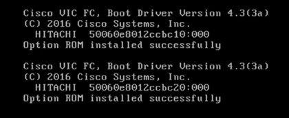
11. The System will automatically boot from the ISO image into the installation wizard.
12. Interrupt the boot process, select the Installation option and press e to edit the kernel options.
![]() The Cisco UCS B480 M5 server SLES 15 GA installation contains a bug (https://www.suse.com/support/kb/doc/?id=7024271) which prevents the installation to complete successfully and requires a driver update disk (DUD). The bug fix will be part of the upcoming maintenance update available shortly after release of this document. Neither SLES 12 SP4 nor SLES 15 SP1 are affected as well as all releases for Cisco UCS B200 M5 server installations. For those installations continue with step 24.
The Cisco UCS B480 M5 server SLES 15 GA installation contains a bug (https://www.suse.com/support/kb/doc/?id=7024271) which prevents the installation to complete successfully and requires a driver update disk (DUD). The bug fix will be part of the upcoming maintenance update available shortly after release of this document. Neither SLES 12 SP4 nor SLES 15 SP1 are affected as well as all releases for Cisco UCS B200 M5 server installations. For those installations continue with step 24.
13. Append on the linuxefi line the parameter dud=1 and press F10 to boot.
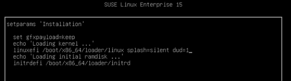
14. While on the Driver Update Screen select in UCS KVM Virtual Media – CD/DVD – Mapped.
15. Select UnMap Drive.
16. Change the file extension of bsc1156167-yast2-storage-ng-v1.dud from dud to iso.
17. Map the driver update disk in UCM KVM Virtual Media – CD/DVD.
18. Choose the line sr0: USB CD-ROM, Cisco vKVM-Mapped vDVD and press OK.
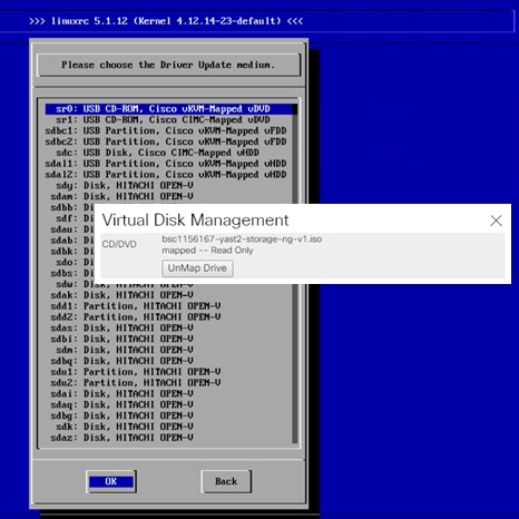
19. The installer reads the driver update disk and returns into the same screen.
20. While on the Driver Update Screen select in UCS KVM Virtual Media – CD/DVD – Mapped.
21. Select UnMap Drive.
22. Map the SLE-15-Installer-DVD-x86_64-GM-DVD1.ISO again in UCM KVM Virtual Media – CD/DVD.
23. In the Driver Update Screen click Back to continue with the installation.
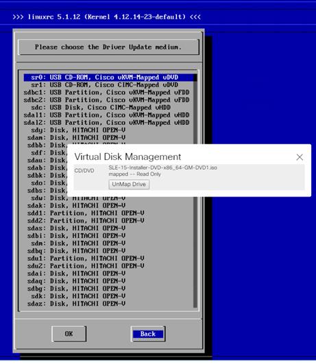
24. On the first “Language, Keyboard and Product Selection” page, select the Language and Keyboard Layout of your choice. Select “SUSE Linux Enterprise Server for SAP Applications 15” to install and click Next.
25. Agree to the SUSE Linux Enterprise for SAP Applications 15 License Agreement and click Next.
26. On the Network Settings screen in the Overview tab, click VNIC Ethernet NIC.
To configure the network interface, identify the Ethernet device to vNIC interface mapping first.
27. In the Navigation pane of Cisco UCS Manager, click Servers.
28. Select Service Profile > root > Sub-Organization > T01-HANA > HANA-ScaleUp-01.
29. In the network tab, scroll down to the vNIC section and list the vNICs with their MAC addresses.
30. Note down the MAC address of the HANA-Mgmt vNIC is “00:25:B5:00:0A:02”
31. By comparing MAC Address on the OS level and within Cisco UCS, eth0 on OS will carry the VLAN for Management.
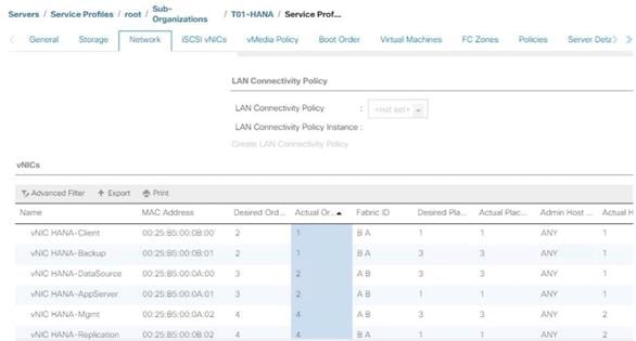
32. Click Edit, under the Address tab.
33. Click Statically Assigned IP Address:
34. In the IP Address field enter <Management IP address>.
35. In the Subnet Mask field enter <subnet mask for Management Interface>.
36. In the Hostname field enter the hostname for Management Interface.
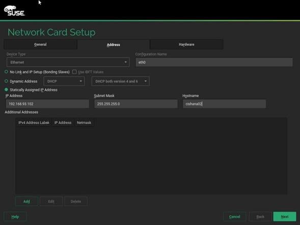
37. Repeat steps 12 and 13 for each vNIC. Alternatively, IP address for vNICs can be set post installation, by using ssh to connect to the server on Management IP or inside the KVM console.
![]() (Optional) Add all further Ethernet Network Configuration on the SSH terminal after the installation wizard finishes.
(Optional) Add all further Ethernet Network Configuration on the SSH terminal after the installation wizard finishes.
38. On the Network Settings screen select Hostname/DNS:
39. In the Hostname field enter the Hostname <var_os_host_name>.
40. In the Domain Name Field enter <var_os_domain_name>.
41. In the Name Server 1 field enter <var_os_dns_server_1> and Name Server 2 field enter <var_os_dns_server_2>.
42. In the Search domains field enter <var_os_domain_name>, <other_os_domain_name>.
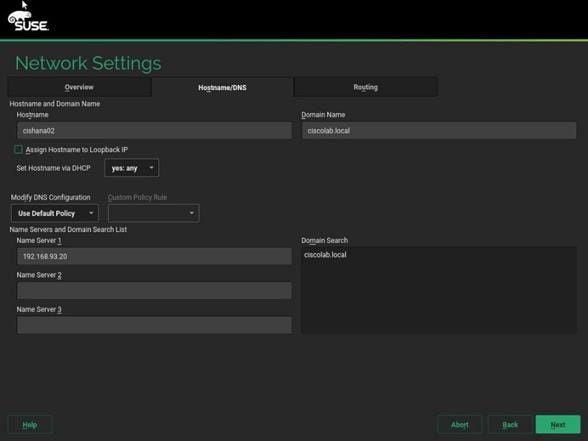
43. On the Network Settings screen select Routing.
44. For the Default IPv4 Gateway enter the IP address <var_os_default_IPv4_gateway>.
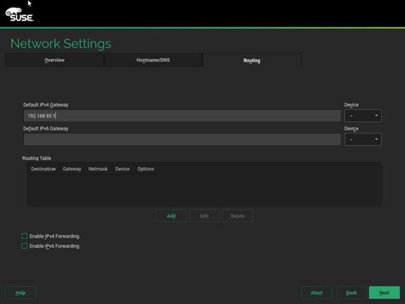
45. Click Next.
46. During ‘System Probing’ – Select ‘Yes’ for the pop-up for Do you want to activate multipath?
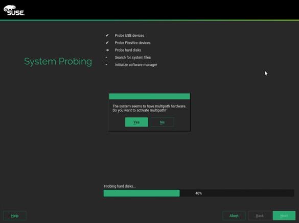
47. On the ‘Registration’ page select Skip Registration.
![]() You will register the system later as part of post-installation tasks. Click ‘Yes’ for the confirmation warning pop-up to proceed.
You will register the system later as part of post-installation tasks. Click ‘Yes’ for the confirmation warning pop-up to proceed.
48. On the ‘Add-On Product’ page checkmark ‘I would like to install an additional Add-On Product’
49. In UCS KVM click the ‘Virtual Media’ button. Select CD/DVD – Mapped and UnMap drive.
50. In UCS KVM click the ‘Virtual Media’ button. Select CD/DVD and map the SLE-15-Packages-x86_64-GM-DVD1.ISO image.
51. On the ‘Add On Product’ page select DVD and click Next.
52. Select the Cisco vKVM-Mapped vDVD drive. Click Continue.
![]() In the ‘Extension and Module Selection’ page select the required modules according to SAP note 2578899 (https://launchpad.support.sap.com/#/notes/2578899).
In the ‘Extension and Module Selection’ page select the required modules according to SAP note 2578899 (https://launchpad.support.sap.com/#/notes/2578899).
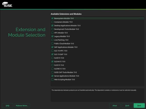
53. Click Next.
54. On the Add-On Product Installation page click Next.
55. On the System Role page, select SLES for SAP Applications can click Next.
56. Clear all check marks on the Choose Operating System Edition page and click Next.
57. On the Suggested Partitioning page select Expert Partitioner.
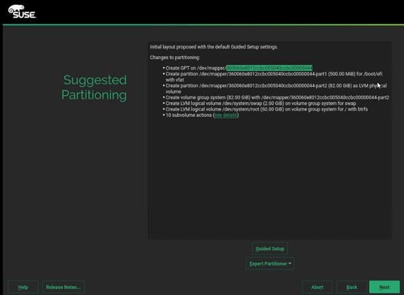
58. On the system view navigation pane select <var_os_host_name> > Volume Management. Delete the proposed operating system volumes to resize the partition.
59. On the system view navigation pane select <var_os_host_name> > Hard Disks > Select a device from the list which has the 82G Linux LVM and resize the device to the maximum available disk space 99.5G.
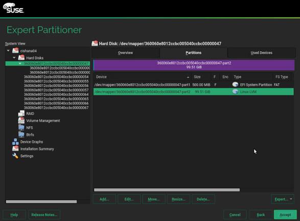
60. On the system view navigation pane select <var_os_host_name> > Volume Management. Create a system volume group and the 2G swap logical volume as well as the 97.5G root logical volume device.
![]() Do not add any additional volume groups now. Multipath and for SAP HANA Scale-Out deployments LVM as well have to be re-configured first.
Do not add any additional volume groups now. Multipath and for SAP HANA Scale-Out deployments LVM as well have to be re-configured first.
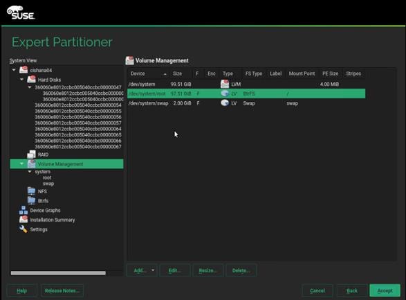
61. Leave the Expert Partitioner and click Accept.
62. Select the Clock and Time Zone settings of your choice, select Hardware clock set to UTC and click Next.
63. Provide the system administrator root password <var_os_root_pw> and click Next.
64. In the Installation Settings screen customize the software selection. Click Software to make the following changes:
a. Deselect GNOME DE
b. Select X Window System.
c. Select SAP HANA Server Base.
d. Deselect SAP Application Sever Base.
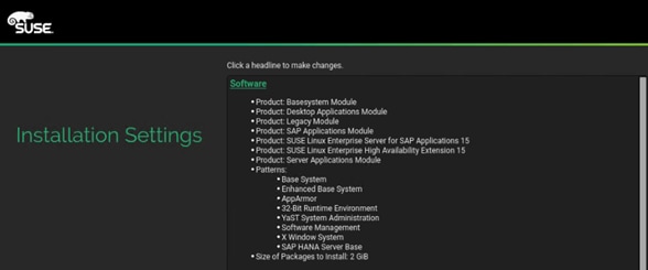
65. Under the Firewall and SSH headline, ‘disable’ the firewall.
66. In the Installation Settings screen click Kdump and disable the kernel dump configuration.

67. In the Installation Settings screen click Default system target and change it to ‘text mode’.
68. Click Install and select Install again for the subsequent ‘Confirm Installation’ prompt. The installation starts.
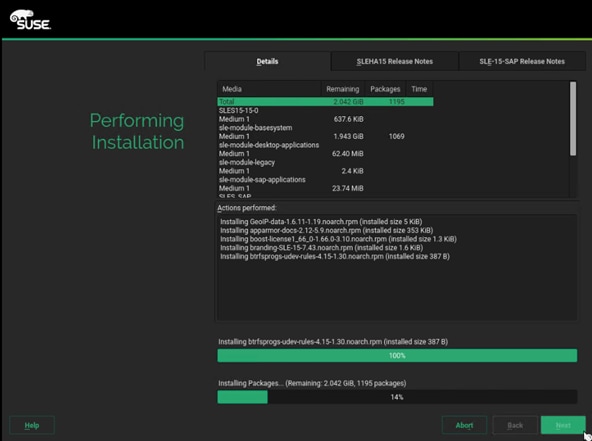
69. When the installation of the Add-On Packages is done, UnMap the virtual disk drive in UCS KVM. Now map the SLE-15-Installer-DVD-x86_64-GM-DVD1.ISO again and click Retry for the installer to continue.
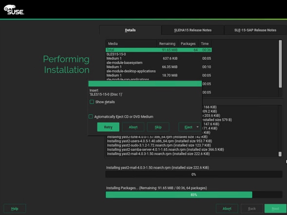
After the Operating System is installed the system will reboot.
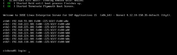
Network Services Configuration
To configure the server with Network services, follow these steps:
Hostnames
The operating system must be configured in such a way that the short name of the server is displayed for the command ‘hostname’ and Full Qualified Host Name is displayed with the command ‘hostname –d’.
1. SSH as root to the management IP address of the server.
2. Confirm the correct hostname settings with the command’s hostname and hostname -d. If not set correctly continue with the next step.
3. Set the hostname using hostnamectl
hostnamectl set-hostname <hostname>
IP Address
Each SAP HANA Server is configured with 6 to 8 vNIC devices. The SAP HANA Scale-Out environment requires additional NFS shared and Internal network configuration. Table 23 lists the required IP address information to configure the IP address on the Operating System level.
![]() The IP Address and Subnet Mask provided below are examples only, please configure the IP address for your environment.
The IP Address and Subnet Mask provided below are examples only, please configure the IP address for your environment.
Table 23 List the IP Address for SAP HANA Server
| vNIC Name |
VLAN ID |
IP Address Range |
Subnet Mask |
| HANA-AppServer |
<var_appserver_vlan_id> |
192.168.223.101 |
255.255.255.0 |
| HANA-Backup |
<var_backup_vlan_id> |
192.168.221.101 |
|
| HANA-Client |
<var_client_vlan_id> |
192.168.222.101 |
|
| HANA-DataSource |
<var_datasource_vlan_id> |
192.168.224.101 |
|
| HANA-Replication |
<var_replication_vlan_id> |
192.168.225.101 |
|
| Management |
<var_mgmt_vlan_id> |
192.168.93.101 |
|
| HANA-NFSShared |
<var_nfsshared_vlan_id> |
192.168.110.101 |
|
| HANA-Internal |
<var_internal_vlan_id> |
192.168.220.101 |
1. The network interface configuration requires correct mapping of the ethernet device on the OS level to the appropriate vNIC interface within the Cisco UCS configuration.
2. From the OS execute the below command to get list of Ethernet device with MAC Address.
ip -br link | grep -v lo | sort | awk '{print $1 " " $3}'
eth0 00:25:b5:00:0a:0e
eth1 00:25:b5:00:0a:0d
eth2 00:25:b5:00:0b:0e
eth3 00:25:b5:00:0a:0f
eth4 00:25:b5:00:0b:0d
eth5 00:25:b5:00:0a:0c
eth6 00:25:b5:00:0b:0c
eth7 00:25:b5:00:0b:0f
3. In the Cisco UCSM navigation pane, click Servers.
4. Select Service Profile > root > Sub-Organization > T01-HANA > HANA-Scale{Up | Out}-01.
5. In the main pane, click Network and scroll down to list the vNICs including their MAC addresses.
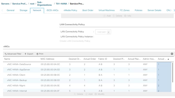
6. Note the MAC Address of the HANA-Client vNIC is “00:25:B5:00:0B:0C”.
7. By comparing MAC Address on the OS and Cisco UCS, eth6 on OS will carry the VLAN for HANA-Client.
8. Go to network configuration directory and create a configuration file for eth6:
vi /etc/sysconfig/network/ifcfg-eth6
BOOTPROTO='static'
BROADCAST=''
ETHTOOL_OPTIONS=''
IPADDR='<IP subnet for HANA-Client/subnet mask example:192.168.222.101/24>
MTU='9000'
NAME='HANA Client Network'
NETWORK=''
REMOTE_IPADDR=''
STARTMODE='auto'
9. Repeat steps 6 to 8 for each vNIC interface.
10. Add default gateway.
vi /etc/sysconfig/network/routes
default 192.168.93.1 - -
DNS
Domain Name Service configuration must be done based on the local requirements.
Add DNS name server entries:
vi /etc/resolv.conf
nameserver <IP of DNS Server1>
nameserver <IP of DNS Server2>
search <Domain_name>
Hosts file
To properly resolve all network IP address in the SAP HANA environment, define the entire network in the operating system host file.
vi /etc/hosts
127.0.0.1 localhost
# special IPv6 addresses
::1 localhost ipv6-localhost ipv6-loopback
#
# Admin / Management
#
192.168.93.8 ucs6332-a
192.168.93.9 ucs6332-b
192.168.93.10 ucsm-a
192.168.93.11 ucsm-b
192.168.93.101 cishana01m.ciscolab.local cishana01m
192.168.93.102 cishana02m.ciscolab.local cishana02m
192.168.93.103 cishana03m.ciscolab.local cishana03m
#
# AppServer
#
192.168.223.101 cishana01.ciscolab.local cishana01
192.168.223.102 cishana02.ciscolab.local cishana02
192.168.223.103 cishana03.ciscolab.local cishana03
#
# Internal
#
192.168.220.101 cishana01i.ciscolab.local cishana01i
192.168.220.102 cishana02i.ciscolab.local cishana02i
192.168.220.103 cishana03i.ciscolab.local cishana03i
#
# …
192.168.222.101 cishana01c.ciscolab.local cishana01c
192.168.224.101 cishana01d.ciscolab.local cishana01d
192.168.225.101 cishana01r.ciscolab.local cishana01r
192.168.221.101 cishana01b.ciscolab.local cishana01b
#
# NFSShared
#
192.168.110.40 evs1.ciscolab.local evs1
![]() The example above is for a SAP HANA Scale-Out environment. It requires a NFS shared HANA volume and the Internal HANA network for the host-to-host communication.
The example above is for a SAP HANA Scale-Out environment. It requires a NFS shared HANA volume and the Internal HANA network for the host-to-host communication.
Network Time
It is important to maintain an exact system time on all components used for SAP HANA. The configuration of NTP is important and needs to be performed on all systems. Since SLES 15, chrony is the default implementation of NTP.
![]() A good practice is to configure either one compute node or the storage as central time server for the whole environment which is synchronized with an external time server. All other servers act as clients.
A good practice is to configure either one compute node or the storage as central time server for the whole environment which is synchronized with an external time server. All other servers act as clients.
1. Add at least one NTP server to the chrony config file /etc/chrony.conf:
vi /etc/chrony.conf
server <var_oob_ntp_ip>
2. Start chrony running following command:
systemctl start chronyd.service
Enable the service to start automatically at boot time
systemctl enable chronyd.service
System Update and Linux Customization
To update and customize the SLES for SAP 15 GA operating system, follow these steps:
![]() If a proxy server is required to access the internet, please update the proxy settings in the file /etc/sysconfig/proxy
If a proxy server is required to access the internet, please update the proxy settings in the file /etc/sysconfig/proxy
1. Register the SUSE Linux Enterprise installation with the SUSE Customer Center:
SUSEConnect -r <Registration Code> -e <email address>
2. Execute zypper to update SLES4SAP 15 to latest patch level and follow the on-screen instructions.
zypper update
3. Modify /etc/sysconfig/sapconf search for the line starting with "#governor = performance” and “energy_perf_bias = performance”. Remove the “#” sign in front of both lines:
vi /etc/sysconfig/sapconf
governor = performance
energy_perf_bias = performance
4. Apply the HANA solution to saptune:
saptune solution apply HANA
WARNING: [block] section detected: Traversing all block devices can take a considerable amount of time.
WARNING: Be aware: system-wide UserTasksMax is now set to infinity according to SAP recommendations.
This opens up entire system to fork-bomb style attacks.
All tuning options for the SAP solution have been applied successfully.
Remember: if you wish to automatically activate the solution's tuning options after a reboot, you must instruct saptune to configure "tuned" daemon by running:
saptune daemon start
5. Start the saptune daemon:
saptune daemon start
Starting daemon (tuned.service), this may take several seconds...
Daemon (tuned.service) has been enabled and started.
6. Rewrite the GRUB2 configurationr:
grub2-mkconfig -o /boot/grub2/grub.cfg
7. Reboot the OS by issuing reboot command.
![]() The Operating System recommended configurations documented in this CVD are derived from SAP Notes at the time of publication. For the latest settings, review the Important SAP Notes.
The Operating System recommended configurations documented in this CVD are derived from SAP Notes at the time of publication. For the latest settings, review the Important SAP Notes.
Install Cisco eNIC and fNIC Driver
![]() All Linux drivers starting with UCS firmware 4.0(4) include an UEFI signature and allow Secure Boot to be switched on in UCSM.
All Linux drivers starting with UCS firmware 4.0(4) include an UEFI signature and allow Secure Boot to be switched on in UCSM.
To download the Cisco UCS Drivers ISO bundle, which contains most of the Cisco UCS Virtual Interface Card drivers, follow these steps:
1. In a web browser, navigate https://software.cisco.com/download/home/283853163/type/283853158/release/4.0(4b)
2. After the download is complete open the ISO image and:
- ucs-bxxx-drivers-linux.4.0.4b.iso\Network\Cisco\VIC\SLES\SLES15 and copy cisco-enic-usnic-kmp-default-3.2.272.23_k4.12.14_23-738.12.x86_64.rpm to the HANA server
- ucs-bxxx-drivers-linux.4.0.4b.iso\Storage\Cisco\VIC\SLES\SLES15 and copy cisco-fnic-kmp-default-2.0.0.42-77.0.x86_64.rpm to the HANA server
3. SSH login as root.
4. Update the enic driver:
rpm -Uvh cisco-enic-usnic-kmp-default-3.2.272.23_k4.12.14_23-738.12.x86_64.rpm
5. Update the fnic driver:
rpm -Uvh cisco-fnic-kmp-default-2.0.0.42-77.0.x86_64.rpm
Multipath Configuration
This reference architecture uses Device-mapper Multipath, a native component of the Linux operating system. Using Device-mapper Multipath allows the configuration of multiple I/O paths between the server blades and storages.
Each node has two I/O paths connected with the storage. Multipathing aggregates all physical I/O paths into a single logical path. The LUNs are always available unless both paths fail.
Device-mapper Multipath is used for the following I/O paths:
· SAP HANA server boot volume
· SAP HANA data volume
· SAP HANA log volume
· SAP HANA shared volume (SAP HANA Scale-Up only)
To configure multipath, follow these steps:
1. SSH login as root.
2. Create the file /etc/multipath.conf:
vi /etc/multipath.conf
blacklist {
devnode "^(ram|raw|loop|fd|md|dm-|sr|scd|st)[0-9]*"
devnode "^(hd)[a-z]"
devnode "^(dcssblk)[0-9]*"
}
devices {
device {
vendor "HITACHI"
product ".*"
user_friendly_names no
path_grouping_policy "multibus"
path_checker "directio"
path_selector "queue-length 0"
uid_attribute ID_SERIAL
failback immediate
rr_weight uniform
rr_min_io_rq 128
features 0
no_path_retry 5
}
}
3. Start the multipath daemon and enable to start at the boot:
systemctl start multipathd
systemctl enable multipathd
4. Check the status of multipath devices using multipath -ll:
multipath -ll
360060e8012ccbc005040ccbc00000048 dm-8 HITACHI,OPEN-V
size=384G features='1 queue_if_no_path' hwhandler='0' wp=rw
`-+- policy='queue-length 0' prio=1 status=active
|- 0:0:0:9 sdad 65:208 active ready running
|- 0:0:1:9 sdan 66:112 active ready running
|- 6:0:0:9 sdj 8:144 active ready running
`- 6:0:1:9 sdt 65:48 active ready running
360060e8012ccbc005040ccbc00000049 dm-7 HITACHI,OPEN-V
size=384G features='1 queue_if_no_path' hwhandler='0' wp=rw
`-+- policy='queue-length 0' prio=1 status=active
|- 0:0:0:8 sdac 65:192 active ready running
|- 0:0:1:8 sdam 66:96 active ready running
|- 6:0:0:8 sdi 8:128 active ready running
`- 6:0:1:8 sds 65:32 active ready running
360060e8012ccbc005040ccbc00000029 dm-0 HITACHI,OPEN-V
size=1.0T features='1 queue_if_no_path' hwhandler='0' wp=rw
`-+- policy='queue-length 0' prio=1 status=active
|- 0:0:0:1 sdv 65:80 active ready running
|- 0:0:1:1 sdaf 65:240 active ready running
|- 6:0:0:1 sdb 8:16 active ready running
`- 6:0:1:1 sdl 8:176 active ready running
360060e8012ccbc005040ccbc0000004a dm-6 HITACHI,OPEN-V
size=384G features='1 queue_if_no_path' hwhandler='0' wp=rw
`-+- policy='queue-length 0' prio=1 status=active
|- 0:0:0:7 sdab 65:176 active ready running
|- 0:0:1:7 sdal 66:80 active ready running
|- 6:0:0:7 sdh 8:112 active ready running
`- 6:0:1:7 sdr 65:16 active ready running
360060e8012ccbc005040ccbc0000004b dm-5 HITACHI,OPEN-V
size=384G features='1 queue_if_no_path' hwhandler='0' wp=rw
`-+- policy='queue-length 0' prio=1 status=active
|- 0:0:0:6 sdaa 65:160 active ready running
|- 0:0:1:6 sdak 66:64 active ready running
|- 6:0:0:6 sdg 8:96 active ready running
`- 6:0:1:6 sdq 65:0 active ready running
360060e8012ccbc005040ccbc00000058 dm-4 HITACHI,OPEN-V
size=128G features='1 queue_if_no_path' hwhandler='0' wp=rw
`-+- policy='queue-length 0' prio=1 status=active
|- 0:0:0:5 sdz 65:144 active ready running
|- 0:0:1:5 sdaj 66:48 active ready running
|- 6:0:0:5 sdf 8:80 active ready running
`- 6:0:1:5 sdp 8:240 active ready running
360060e8012ccbc005040ccbc00000059 dm-3 HITACHI,OPEN-V
size=128G features='1 queue_if_no_path' hwhandler='0' wp=rw
`-+- policy='queue-length 0' prio=1 status=active
|- 0:0:0:4 sdy 65:128 active ready running
|- 0:0:1:4 sdai 66:32 active ready running
|- 6:0:0:4 sde 8:64 active ready running
`- 6:0:1:4 sdo 8:224 active ready running
360060e8012ccbc005040ccbc0000005a dm-2 HITACHI,OPEN-V
size=128G features='1 queue_if_no_path' hwhandler='0' wp=rw
`-+- policy='queue-length 0' prio=1 status=active
|- 0:0:0:3 sdx 65:112 active ready running
|- 0:0:1:3 sdah 66:16 active ready running
|- 6:0:0:3 sdd 8:48 active ready running
`- 6:0:1:3 sdn 8:208 active ready running
360060e8012ccbc005040ccbc0000005b dm-1 HITACHI,OPEN-V
size=128G features='1 queue_if_no_path' hwhandler='0' wp=rw
`-+- policy='queue-length 0' prio=1 status=active
|- 0:0:0:2 sdw 65:96 active ready running
|- 0:0:1:2 sdag 66:0 active ready running
|- 6:0:0:2 sdc 8:32 active ready running
`- 6:0:1:2 sdm 8:192 active ready running
5. For the SAP HANA Scale-Out environment, additional configuration is required:
a. Adapt the /etc/lvm/lvm.conf configuration file:
vi /etc/lvm/lvm.conf
filter = ["a|/dev/mapper/.*|", "r|.*/|"]
use_lvmetad = 0
b. Restart the LVM service:
systemctl restart lvm2-lvmetad
c. Create the file /etc/dracut.conf.d/10-mp.conf:
echo 'force_drivers+="dm_multipath dm_service_time"' >> /etc/dracut.conf.d/10-mp.conf
6. Use dracut to include multipath (and the LVM changes for Scale-Out) in the initrd image:
dracut –kver $(uname -r) -f -a multipath
SAP HANA Persistent Storage Volume Configuration
For SUSE Linux Enterprise Server for SAP Applications use an LVM-based storage layout. Once the operating system is installed and correctly configured all assigned LUNs are visible. For example:
/dev/mapper/360060e801227fc00504027fc00000101
/dev/disk/by-id/scsi-360060e801227fc00504027fc00000101
The last 6 digits of this number indicate the LDEV ID used during the LUN assignment. In the example above, 000101 maps to LDEV ID: 00:01:01.
1. Login to the Hitachi Storage Navigator. In our lab environment server05 is the first host of the SAP HANA Scale-Out installation. In the Explorer window select VSP Gx00 - Ports/Host Groups/iSCSI Targets - CL1-A -Server05 (03).
2. Select the LUNs tab on the right-hand screen to display which LDEV ID belongs to which LDEV name.

3. Initialize all LUNs beside the one hosting the operating system so LVM can access them.
pvcreate -ff -y /dev/mapper/360060e8012ccbc005040ccbc00000048 /dev/mapper/360060e8012ccbc005040ccbc00000049 /dev/mapper/360060e8012ccbc005040ccbc0000004a /dev/mapper/360060e8012ccbc005040ccbc0000004b
pvcreate -ff -y /dev/mapper/360060e8012ccbc005040ccbc00000058 /dev/mapper/360060e8012ccbc005040ccbc00000059 /dev/mapper/360060e8012ccbc005040ccbc0000005a /dev/mapper/360060e8012ccbc005040ccbc0000005b
4. Create volume groups from the physical volumes. Volume group naming differs between Scale-Up and Scale-Out installations.
- For SAP HANA Scale-Up use the volume group names vgdata, vglog, vgshared.
- For SAP HANA Scale-Out use the volume group names vgdata0{1|2|3|4} and vglog0{1|2|3|4} for a 4-node scale-out environment with 4 worker nodes.
vgcreate vgdata01 /dev/mapper/360060e8012ccbc005040ccbc00000048 /dev/mapper/360060e8012ccbc005040ccbc00000049 /dev/mapper/360060e8012ccbc005040ccbc0000004a /dev/mapper/360060e8012ccbc005040ccbc0000004b
vgcreate vglog01 /dev/mapper/360060e8012ccbc005040ccbc00000058 /dev/mapper/360060e8012ccbc005040ccbc00000059 /dev/mapper/360060e8012ccbc005040ccbc0000005a /dev/mapper/360060e8012ccbc005040ccbc0000005b
![]() To create other volume groups, use the same syntax, exchanging the volume group name as well as the physical disks or LUNs.
To create other volume groups, use the same syntax, exchanging the volume group name as well as the physical disks or LUNs.
5. Create a logical volume group for each volume group available.
lvcreate -y -n lvdata vgdata01 -l 100%FREE --stripesize 1024 -i4 /dev/mapper/360060e8012ccbc005040ccbc00000048 /dev/mapper/360060e8012ccbc005040ccbc00000049 /dev/mapper/360060e8012ccbc005040ccbc0000004a /dev/mapper/360060e8012ccbc005040ccbc0000004b
# lvcreate -y -n lvlog vglog01 -l 100%FREE --stripesize 1024 -i4 /dev/mapper/360060e8012ccbc005040ccbc00000058 /dev/mapper/360060e8012ccbc005040ccbc00000059 /dev/mapper/360060e8012ccbc005040ccbc0000005a /dev/mapper/360060e8012ccbc005040ccbc0000005b
![]() To create other logical volume groups, use the same syntax, exchanging the volume group name as well as the physical disks or LUNs.
To create other logical volume groups, use the same syntax, exchanging the volume group name as well as the physical disks or LUNs.
6. Construct a XFS file system on each logical volume:
mkfs.xfs -f /dev/mapper/vgdata01-lvdata
mkfs.xfs -f /dev/mapper/vglog01-lvlog
7. Confirm the volumes are visible on each host:
lvs
LV VG Attr LSize Pool …
root system -wi-ao---- 60.00g
swap system -wi-ao---- 2.00g
lvdata vgdata01 -wi-a----- 1.50t
lvdata vgdata02 -wi-a----- 1.50t
lvlog vglog01 -wi-a----- 511.98g
lvlog vglog02 -wi-a----- 511.98g
8. Create mount directories for the data, log, and HANA shared file systems:
mkdir -p -m 755 /hana/data
mkdir -p -m 755 /hana/log
mkdir -p -m 755 /hana/shared
SAP HANA Scale-Up
1. Add the following entries to /etc/fstab:
# HANA Volume
/dev/mapper/vgshared-lvshared /hana/shared xfs inode64,nobarrier 0 0
/dev/mapper/vgdata-lvdata /hana/data xfs inode64,nobarrier 0 0
/dev/mapper/vglog-lvlog /hana/log xfs inode64,nobarrier 0 0
2. Use the following command to mount the file systems from /etc/fstab:
mount -a
SAP HANA Scale-Out
1. Persist the HANA shared volume only and add the following entry to /etc/fstab:
# HANA Volume
192.168.110.40:/hana_shared_10 /hana/shared nfs \\ vers=3,proto=tcp,hard,intr,timeo=600,retrans=2,wsize=65536,rsize=65536 0 0
2. Use the following command to mount the file systems from /etc/fstab:
mount -a
![]() SAP HANA Scale-Out uses the SAP HANA storage API to manage the HANA data and log volume. Do not add the data and log volume groups to /etc/fstab.
SAP HANA Scale-Out uses the SAP HANA storage API to manage the HANA data and log volume. Do not add the data and log volume groups to /etc/fstab.
Persistent Memory Configuration
The utility ipmctl is used for configuring and managing Intel Optane DC persistent memory modules (DCPMM) and the ndctl utility library is required for managing the libnvdimm (non-volatile memory device) sub-system in the Linux kernel.
To configure Intel Persistent Memory using host tools, follow these steps:
1. SSH login as root.
2. Install the ipmctl host utility:
zypper in ipmctl
The following 2 NEW packages are going to be installed:
ipmctl libndctl6
2 new packages to install.
Overall download size: 487.7 KiB. Already cached: 0 B. After the operation, additional 3.4 MiB will be used.
Continue? [y/n/v/...? shows all options] (y): y
Retrieving package libndctl6-63-3.5.1.x86_64 (1/2), 87.6 KiB (188.0 KiB unpacked)
Retrieving: libndctl6-63-3.5.1.x86_64.rpm ............................[done]
Retrieving package ipmctl-01.00.00.3440-1.6.1.x86_64 (2/2), 400.1 KiB ( 3.2 MiB unpacked)
Retrieving: ipmctl-01.00.00.3440-1.6.1.x86_64.rpm ....................[done]
Checking for file conflicts: .........................................[done]
(1/2) Installing: libndctl6-63-3.5.1.x86_64...........................[done]
(2/2) Installing: ipmctl-01.00.00.3440-1.6.1.x86_64...................[done]
3. Install the ndctl utility library:
zypper in ndctl
The following NEW package is going to be installed:
ndctl
1 new package to install.
Overall download size: 147.2 KiB. Already cached: 0 B. After the operation, additional 252.1 KiB will be used.
Continue? [y/n/v/...? shows all options] (y): y
Retrieving package ndctl-63-3.5.1.x86_64 (1/1), 147.2 KiB (252.1 KiB unpacked)
Retrieving: ndctl-63-3.5.1.x86_64.rpm ................................[done]
Checking for file conflicts: .........................................[done]
(1/1) Installing: ndctl-63-3.5.1.x86_64 ..............................[done]
4. Confirm the persistent memory modules are discovered in the system and verify the software can communicate with them:
ipmctl show -dimm
DimmID | Capacity | HealthState | ActionRequired | LockState | FWVersion
==============================================================================
0x0001 | 252.4 GiB | Healthy | 0 | Disabled | 01.02.00.5367
0x0011 | 252.4 GiB | Healthy | 0 | Disabled | 01.02.00.5367
0x0021 | 252.4 GiB | Healthy | 0 | Disabled | 01.02.00.5367
0x0101 | 252.4 GiB | Healthy | 0 | Disabled | 01.02.00.5367
0x0111 | 252.4 GiB | Healthy | 0 | Disabled | 01.02.00.5367
0x0121 | 252.4 GiB | Healthy | 0 | Disabled | 01.02.00.5367
0x1001 | 252.4 GiB | Healthy | 0 | Disabled | 01.02.00.5367
0x1011 | 252.4 GiB | Healthy | 0 | Disabled | 01.02.00.5367
0x1021 | 252.4 GiB | Healthy | 0 | Disabled | 01.02.00.5367
0x1101 | 252.4 GiB | Healthy | 0 | Disabled | 01.02.00.5367
0x1111 | 252.4 GiB | Healthy | 0 | Disabled | 01.02.00.5367
0x1121 | 252.4 GiB | Healthy | 0 | Disabled | 01.02.00.5367
0x2001 | 252.4 GiB | Healthy | 0 | Disabled | 01.02.00.5367
0x2011 | 252.4 GiB | Healthy | 0 | Disabled | 01.02.00.5367
0x2021 | 252.4 GiB | Healthy | 0 | Disabled | 01.02.00.5367
0x2101 | 252.4 GiB | Healthy | 0 | Disabled | 01.02.00.5367
0x2111 | 252.4 GiB | Healthy | 0 | Disabled | 01.02.00.5367
0x2121 | 252.4 GiB | Healthy | 0 | Disabled | 01.02.00.5367
0x3001 | 252.4 GiB | Healthy | 0 | Disabled | 01.02.00.5367
0x3011 | 252.4 GiB | Healthy | 0 | Disabled | 01.02.00.5367
0x3021 | 252.4 GiB | Healthy | 0 | Disabled | 01.02.00.5367
0x3101 | 252.4 GiB | Healthy | 0 | Disabled | 01.02.00.5367
0x3111 | 252.4 GiB | Healthy | 0 | Disabled | 01.02.00.5367
0x3121 | 252.4 GiB | Healthy | 0 | Disabled | 01.02.00.5367
5. Create the goal:
ipmctl create -goal
The following configuration will be applied:
SocketID | DimmID | MemorySize | AppDirect1Size | AppDirect2Size
==================================================================
0x0000 | 0x0001 | 0.0 GiB | 252.0 GiB | 0.0 GiB
0x0000 | 0x0011 | 0.0 GiB | 252.0 GiB | 0.0 GiB
0x0000 | 0x0021 | 0.0 GiB | 252.0 GiB | 0.0 GiB
0x0000 | 0x0101 | 0.0 GiB | 252.0 GiB | 0.0 GiB
0x0000 | 0x0111 | 0.0 GiB | 252.0 GiB | 0.0 GiB
0x0000 | 0x0121 | 0.0 GiB | 252.0 GiB | 0.0 GiB
0x0001 | 0x1001 | 0.0 GiB | 252.0 GiB | 0.0 GiB
0x0001 | 0x1011 | 0.0 GiB | 252.0 GiB | 0.0 GiB
0x0001 | 0x1021 | 0.0 GiB | 252.0 GiB | 0.0 GiB
0x0001 | 0x1101 | 0.0 GiB | 252.0 GiB | 0.0 GiB
0x0001 | 0x1111 | 0.0 GiB | 252.0 GiB | 0.0 GiB
0x0001 | 0x1121 | 0.0 GiB | 252.0 GiB | 0.0 GiB
0x0002 | 0x2001 | 0.0 GiB | 252.0 GiB | 0.0 GiB
0x0002 | 0x2011 | 0.0 GiB | 252.0 GiB | 0.0 GiB
0x0002 | 0x2021 | 0.0 GiB | 252.0 GiB | 0.0 GiB
0x0002 | 0x2101 | 0.0 GiB | 252.0 GiB | 0.0 GiB
0x0002 | 0x2111 | 0.0 GiB | 252.0 GiB | 0.0 GiB
0x0002 | 0x2121 | 0.0 GiB | 252.0 GiB | 0.0 GiB
0x0003 | 0x3001 | 0.0 GiB | 252.0 GiB | 0.0 GiB
0x0003 | 0x3011 | 0.0 GiB | 252.0 GiB | 0.0 GiB
0x0003 | 0x3021 | 0.0 GiB | 252.0 GiB | 0.0 GiB
0x0003 | 0x3101 | 0.0 GiB | 252.0 GiB | 0.0 GiB
0x0003 | 0x3111 | 0.0 GiB | 252.0 GiB | 0.0 GiB
0x0003 | 0x3121 | 0.0 GiB | 252.0 GiB | 0.0 GiB
Do you want to continue? [y/n] y
6. Reboot the server for the new memory allocations.
7. Verify the regions created:
ipmctl show -region
SocketID | ISetID | Persistent | Capacity | FreeCapacity | HealthState
| | MemoryType | | |
==============================================================================
0x0000 | 0xd7…9c2ccc | AppDirect | 1512.0 GiB | 0.0 GiB | Healthy
0x0001 | 0xfb…9b2ccc | AppDirect | 1512.0 GiB | 0.0 GiB | Healthy
0x0002 | 0xc6…af2ccc | AppDirect | 1512.0 GiB | 0.0 GiB | Healthy
0x0003 | 0x68…9f2ccc | AppDirect | 1512.0 GiB | 0.0 GiB | Healthy
8. Create a name space for each region; on a server with a total of 4 CPU invoke the command four times:
ndctl create-namespace
9. List the active name spaces previously created:
# ndctl list
[
{
"dev":"namespace1.0",
"mode":"fsdax",
"map":"dev",
"size":1598128390144,
"uuid":"f722c877-97da-48b0-b18e-dcd0842a633b",
"blockdev":"pmem1"
},
{
"dev":"namespace3.0",
"mode":"fsdax",
"map":"dev",
"size":1598128390144,
"uuid":"a87f5c10-e71a-40d5-8264-99a25fe93b72",
"blockdev":"pmem3"
},
{
"dev":"namespace0.0",
"mode":"fsdax",
"map":"dev",
"size":1598128390144,
"uuid":"3677e9f3-6536-4a15-902d-42ffb0182500",
"blockdev":"pmem0"
},
{
"dev":"namespace2.0",
"mode":"fsdax",
"map":"dev",
"size":1598128390144,
"uuid":"549b567c-4f01-4831-8a6f-877c8f672d01",
"blockdev":"pmem2"
}
]
10. Create a file system and mount the persistent memory modules:
mkfs -t xfs -f /dev/pmem0
mkfs -t xfs -f /dev/pmem1
mkfs -t xfs -f /dev/pmem2
mkfs -t xfs -f /dev/pmem3
mkdir -p /hana/pmem/nvmem0
mkdir -p /hana/pmem/nvmem1
mkdir -p /hana/pmem/nvmem2
mkdir -p /hana/pmem/nvmem3
mount -t xfs -o dax /dev/pmem0 /hana/pmem/nvmem0
mount -t xfs -o dax /dev/pmem1 /hana/pmem/nvmem1
mount -t xfs -o dax /dev/pmem2 /hana/pmem/nvmem2
mount -t xfs -o dax /dev/pmem3 /hana/pmem/nvmem3
11. Add the mount points to the /etc/fstab file to make them permanent:
# vi /etc/fstab
/dev/pmem0 /hana/pmem/nvmem0 xfs rw,relatime,attr2,dax,inode64,noquota 0 0
/dev/pmem1 /hana/pmem/nvmem1 xfs rw,relatime,attr2,dax,inode64,noquota 0 0
/dev/pmem2 /hana/pmem/nvmem2 xfs rw,relatime,attr2,dax,inode64,noquota 0 0
/dev/pmem3 /hana/pmem/nvmem3 xfs rw,relatime,attr2,dax,inode64,noquota 0 0
Red Hat Enterprise Linux for SAP Solutions 7.6 OS Installation
This section provides the procedure for RedHat Enterprise Linux 7.6 Operating System and customizing for SAP HANA environments.
![]() The following procedure requires RHEL 7.6 installation ISO image.
The following procedure requires RHEL 7.6 installation ISO image.
To install a RHEL 7.6 system, follow these steps:
1. In the Cisco UCSM navigation pane, click Servers.
2. Select Service Profile > root > Sub-Organization > T01-HANA > HANA-ScaleOut-03.
3. Click KVM Console.
4. When the KVM Console is launched, choose Virtual Media > Activate Virtual Devices.
5. For Unencrypted Virtual Media Session, select Accept this Session and then click Apply.
6. Click Virtual Media again and choose CD/DVD.
7. Browse to navigate to the ISO media location and select rhel-server-7.6-x86_64-dvd.iso. Click Open.
8. Click Map Device.
9. Select the button “server actions” and boot the server. Click OK to proceed.
10. At server boot time, during verification of VIC FC boot driver version, it recognizes the Hitachi Storage by its target WWPN numbers. This verifies the server to storage connectivity.
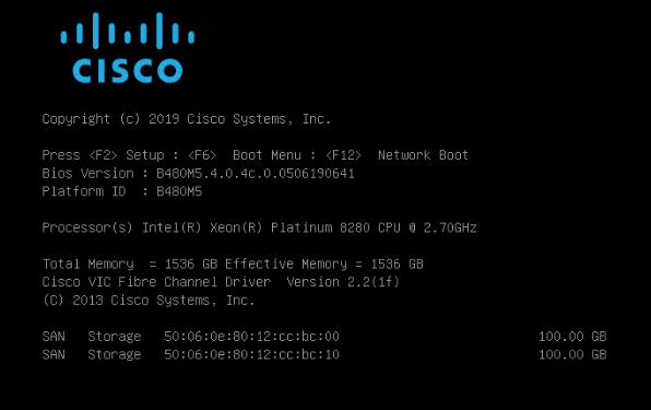
11. On the Initial screen choose Install Red Hat Enterprise Linux 7.6 to start the installation process.
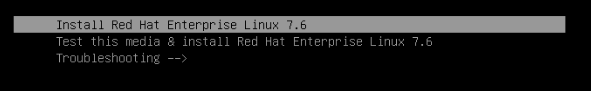
12. Choose Language and click Continue.
13. The Installation Summary page displays.
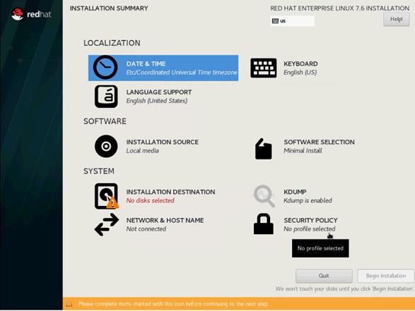
14. Click Date & Time; choose the appropriate time zone and click Done.
15. Click Keyboard; choose Keyboard layout and click Done.
16. Under Software, click Software Selection:
a. Choose Infrastructure Server as base environment.
b. Select the following Add-Ons for Selected Environments: Large Systems Performance, Network File System Client, Performance Tools, Compatibility Libraries and click Done to confirm the selection.
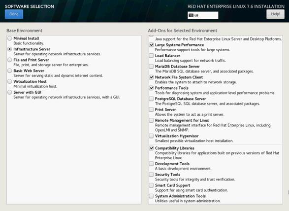
17. Under the System section, select Installation destination.
18. In the Select Specialized & Network Disks section click Add a disk.
19. Under Multipath Devices, select the single 100G device identifies by its WWID. Click Done.
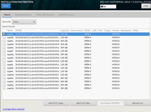
20. From the Other Storage Options section choose I will configure partitioning and click Done.
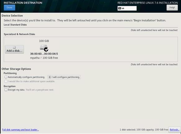
21. In the Manual Partitioning screen, choose the Standard Partition scheme.
22. Select the link Click here to create them automatically.
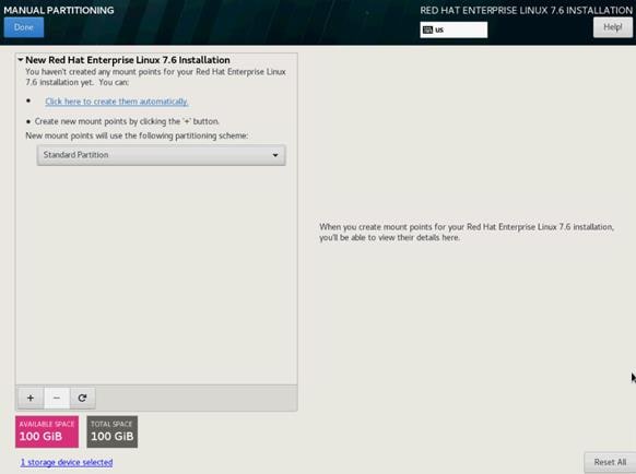
23. Remove the home partition. Select the /home partition and click the “-“ symbol to remove the partition.
24. Select the swap partition and change the capacity from 4096 to 2048 GiB. Click Update Settings.
25. Select the / partition and change the capacity from 50 GiB to 96.8 GiB. Click Update Settings.
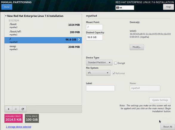
26. Keep the other default settings and click Done.
27. Review the change summary and accept the changes.
28. In the System section click KDUMP.
29. Remove the checkmark from enable kdump and click Done.
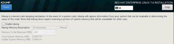 .
.
30. In the System section, click Network & Host Name.
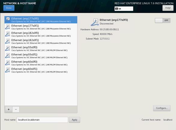
31. Enter the Host name and click Apply.
32. The network interface configuration requires correct mapping of the network interfaces on the OS level to the appropriate vNIC interface within the Cisco UCS configuration.
33. In the Cisco UCSM navigation pane, click Servers.
34. Select Service Profile > root > Sub-Organization > T01-HANA > HANA-ScaleOut-03.
35. On the main pane, click Network and list the vNICs including their MAC addresses.
36. Note down the MAC address of the HANA-Mgmt vNIC which is 00:25:B5:00:0A:12.
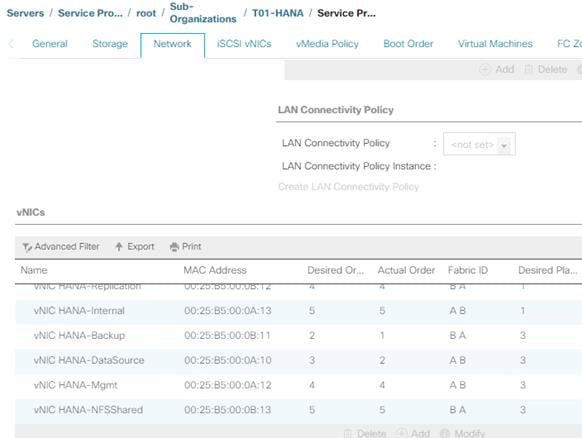
37. By comparing MAC Address on the OS level and within Cisco UCSM, Ethernet interface enp182s0f0 will carry the VLAN for Management.
38. Click Configure:
a. Click IPv4 Settings and choose method Manual.
b. Under Addresses Click Add.
c. In the Address field enter <Management IP address>.
d. In the Netmask field enter <subnet mask for Management Interface>.
e. In the Gateway field enter <default gateway for Management Interface>.
39. Click Save.
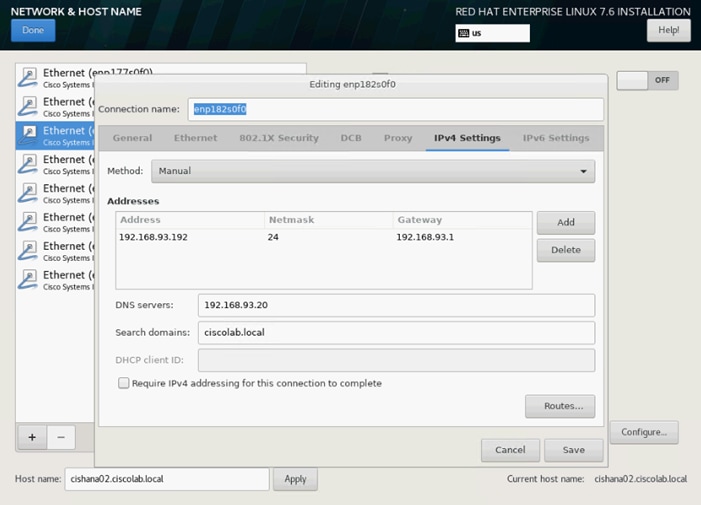
40. Turn the interface ON.
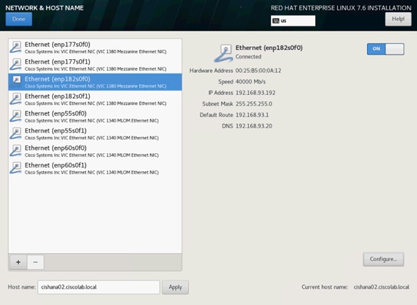
41. Click Done.
![]() IP address for the other ethernet interfaces will be configured post installation.
IP address for the other ethernet interfaces will be configured post installation.
42. Review the installation summary and click Begin Installation.
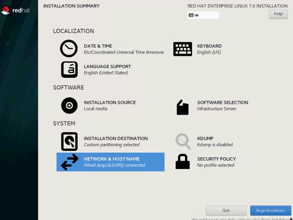
The next screen will show the start of the OS installation.
43. Click Root Password.
44. Enter the Root Password <var_os_root_pw> and Confirm.
45. Click Done. The installation continues.
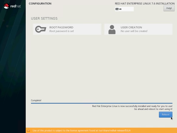
46. When the installation is complete click Reboot to finish the installation.
Network Services Configuration
Continue the installation with the network services configuration.
Hostnames
Use the command hostname to display the short hostname and hostname -f to display the long, full qualified hostname.
1. Open an SSH terminal to the <Management IP address>
2. Logon with user root and password <var_os_root_pw>
3. Confirm the correct hostname settings or alter the hostname with the following command:
hostnamectl set-hostname <var_os_host_name>
4. Append the full qualified hostname to the /etc/hosts file:
echo “<Management IP address> <var_os_host_name>.<var_os_domain name> <var_os_hostname> >> /etc/hosts
IP Address
Each SAP HANA Server is configured with 6 vNIC devices (8 vNIC devices for SAP HANA Scale-Out). Table 24 lists the IP Address information required to configure the IP address on the Operating System.
![]() The IP Address and Subnet Mask in Table 24 are examples only, please configure the IP address for your environment.
The IP Address and Subnet Mask in Table 24 are examples only, please configure the IP address for your environment.
Table 24 IP Addresses for SAP HANA Server
| vNIC Name |
VLAN ID |
IP Address Range |
Subnet Mask |
| HANA-AppServer |
<var_appserver_vlan_id> |
192.168.223.102 |
255.255.255.0 |
| HANA-Backup |
<var_backup_vlan_id> |
192.168.221.102 |
255.255.255.0 |
| HANA-Client |
<var_client_vlan_id> |
192.168.222.102 |
255.255.255.0 |
| HANA-DataSource |
<var_datasource_vlan_id> |
192.168.224.102 |
255.255.255.0 |
| HANA-Replication |
<var_replication_vlan_id> |
192.168.225.102 |
255.255.255.0 |
| Management |
<var_mgmt_vlan_id> |
192.168.93.102 |
255.255.255.0 |
| SAP HANA Scale-Out only |
|||
| HANA-Internal |
<var_internal_vlan_id> |
192.168.220.102 |
255.255.255.0 |
| HANA-NFSShared |
<var_nfsshared_vlan_id> |
192.168.110.102 |
255.255.255.0 |
To configure the network interface on the OS level, identify the OS to vNIC interface mapping from within the Cisco UCS manager first.
With Red Hat Enterprise Linux the traditional way of network interface naming and assignment to the corresponding MAC address changed. By default, fixed names are assigned based on firmware, topology, and PCI location information, like ‘enp182s0f0’. Although it is technical possible to fall back into legacy mode with ethX style naming convention this is no longer the recommended configuration.
As the new naming style is harder to read consider changing the “name” parameter of the network interface configuration file to a more meaningful name like in the example below.
vi / etc/sysconfig/network-scripts- ifcfg-enp182s0
NAME="Management IP (enp182s0)"
With this naming convention, though names stay fixed even if hardware is added or removed it is often harder to read unlike traditional kernel-native ethX naming “eth0”. Another way to name network interfaces, “biosdevnames”, is already available with installation.
1. SSH as root to the <Management IP address>.
2. Run the following command to get list of Ethernet device with MAC Address:
# ip link | grep -v lo
2: enp55s0f0: <BROADCAST,MULTICAST,UP,LOWER_UP> mtu 9000 qdisc mq state UP mode
DEFAULT group default qlen 1000
link/ether 00:25:b5:00:0b:18 brd ff:ff:ff:ff:ff:ff
3: enp55s0f1: <BROADCAST,MULTICAST,UP,LOWER_UP> mtu 9000 qdisc mq state UP mode
DEFAULT group default qlen 1000
link/ether 00:25:b5:00:0a:19 brd ff:ff:ff:ff:ff:ff
4: enp60s0: <BROADCAST,MULTICAST,UP,LOWER_UP> mtu 9000 qdisc mq state UP mode
DEFAULT group default qlen 1000
link/ether 00:25:b5:00:0b:1a brd ff:ff:ff:ff:ff:ff
5: enp177s0f0: <BROADCAST,MULTICAST,UP,LOWER_UP> mtu 9000 qdisc mq state UP mode
DEFAULT group default qlen 1000
link/ether 00:25:b5:00:0b:19 brd ff:ff:ff:ff:ff:ff
6: enp177s0f1: <BROADCAST,MULTICAST,UP,LOWER_UP> mtu 9000 qdisc mq state UP mode
DEFAULT group default qlen 1000
link/ether 00:25:b5:00:0a:18 brd ff:ff:ff:ff:ff:ff
7: enp182s0: <BROADCAST,MULTICAST,UP,LOWER_UP> mtu 9000 qdisc mq state UP mode
DEFAULT group default qlen 1000
link/ether 00:25:b5:00:0a:1a brd ff:ff:ff:ff:ff:ff
3. In the Navigation pane of the Cisco UCS Manager, click Servers.
4. Select Service Profile > root > Sub-Organization > T01-HANA > HANA-ScaleUp-03
5. In the main pane click Network; list the vNICs and their MAC addresses.
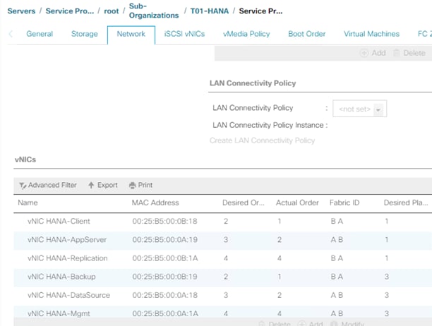
6. Note the MAC Address of the HANA-Client vNIC is “00:25:B5:00:0B:18”.
7. By comparing MAC Address on the OS level and in Cisco UCS, network interface enp55s0f0 will carry the VLAN for HANA-Client.
![]() The default gateway file is deprecated, specify the gateway in per-interface configuration files only.
The default gateway file is deprecated, specify the gateway in per-interface configuration files only.
8. Create a network interface configuration file for enp55s0f0:
vi /etc/sysconfig/network-scripts/ifcfg-enp55s0f0
TYPE=Ethernet
PROXY_METHOD=none
BROWSER_ONLY=no
BOOTPROTO=none
DEFROUTE=yes
IPV4_FAILURE_FATAL=no
IPV6INIT=yes
IPV6_AUTOCONF=yes
IPV6_DEFROUTE=yes
IPV6_FAILURE_FATAL=no
IPV6_ADDR_GEN_MODE=stable-privacy
NAME=HANA Client IP (enp55s0f0)
UUID=fe013edc-3e98-4022-85d4-60b7bd63d1f0
DEVICE=enp55s0f0
ONBOOT=yes
IPADDR=<HANA Client network IP address>
PREFIX=24
GATEWAY="<IP of Default Gateway>"
DNS1="<IP of DNS Server1>"
DOMAIN="<Domain_name>"
IPV6_PRIVACY=no
![]() Repeat steps 3 through 8 for each vNIC interface.
Repeat steps 3 through 8 for each vNIC interface.
9. Reload the connection profiles:
nmcli connection reload
10. Put the changed interfaced down and up again to activate the interfaces:
nmcli dev disconnect enp55s0f0
nmcli con up enp55s0f0
DNS
Domain Name Service configuration must be done based on the local requirements.
Add DNS Servers entries:
vi /etc/resolv.conf
nameserver <IP of DNS Server1>
nameserver <IP of DNS Server2>
search <Domain_name>
Hosts File
To properly resolve all network IP address in the SAP HANA environment, define the entire network in the operating system host file.
vi /etc/hosts
127.0.0.1 localhost
::1 localhost ipv6-localhost ipv6-loopback
#
# Admin / Management
#
192.168.93.8 ucs6332-a
192.168.93.9 ucs6332-b
192.168.93.10 ucsm-a
192.168.93.11 ucsm-b
192.168.93.101 cishana01m.ciscolab.local cishana01m
192.168.93.102 cishana02m.ciscolab.local cishana02m
192.168.93.103 cishana03m.ciscolab.local cishana03m
#
# AppServer
#
192.168.223.101 cishana01.ciscolab.local cishana01
192.168.223.102 cishana02.ciscolab.local cishana02
192.168.223.103 cishana03.ciscolab.local cishana03
#
# Internal
#
192.168.220.101 cishana01i.ciscolab.local cishana01i
192.168.220.102 cishana02i.ciscolab.local cishana02i
192.168.220.103 cishana03i.ciscolab.local cishana03i
#
# …
192.168.222.101 cishana01c.ciscolab.local cishana01c
192.168.224.101 cishana01d.ciscolab.local cishana01d
192.168.225.101 cishana01r.ciscolab.local cishana01r
192.168.221.101 cishana01b.ciscolab.local cishana01b
#
# NFSShared
#
192.168.110.40 evs1.ciscolab.local evs1
![]() The example above is for a SAP HANA Scale-Out environment. It requires a NFS shared HANA volume and the Internal HANA network for the host-to-host communication.
The example above is for a SAP HANA Scale-Out environment. It requires a NFS shared HANA volume and the Internal HANA network for the host-to-host communication.
System Update and Linux Customization
To update and customize SAP HANA, follow these steps:
1. If proxy server is required to access the internet, please update the proxy settings using:
subscription-manager config --server.proxy_hostname=<proxy_server_IP_address>
subscription-manager config --server.proxy_port=<proxy_server_port>
2. In order to patch the system, the repository must be updated. Note that the installed system doesn’t include any update information. In order to patch the RedHat System, it must be registered and attached to a valid Subscription. The following line will register the installation and update the repository information:
subscription-manager register --auto-attach
Username: <Red Hat user name>
Password: <Red Hat user password>
3. Attach the “SAP HANA” subscription. Find the pool ID of your subscription and attach the pool:
subscription-manager list --available
subscription-manager attach --pool=<Subscription Pool ID>
4. Add the repos required for SAP HANA:
subscription-manager repos --disable "*"
subscription-manager repos --enable=rhel-7-server-rpms --enable=rhel-sap-hana-for-rhel-7-server-rpms
5. Verify the SAP HANA repositories have been added successfully:
yum repolist
6. Update only the OS kernel and firmware packages to the latest release that appeared in RHEL 7.6. Set the release version to 7.6 and clear the yum cache:
subscription-manager release --set=7.6
yum clean all
7. Apply the latest updates for RHEL 7.6 Typically, the kernel is updated as well:
yum -y update
8. Prepare the Red Hat Enterprise Linux OS based on SAP Note 2292690:
yum -y install tuned-profiles-sap-hana
9. Start and enable the “tuned” daemon:
systemctl start tuned
systemctl enable tuned
10. Configure the tuned profile. The tuned profile "sap-hana" contains many of the HANA specific configurations and settings. Therefore the "sap-hana" tuned profile must be activated on all systems running SAP HANA:
tuned-adm profile sap-hana
11. Disable SELinux:
sed -i 's/^SELINUX=enforcing/SELINUX=disabled/g' /etc/sysconfig/selinux
sed -i 's/^SELINUX=permissive/SELINUX=disabled/g' /etc/sysconfig/selinux
sed -i 's/^SELINUX=enforcing/SELINUX=disabled/g' /etc/selinux/config
sed -i 's/^SELINUX=permissive/SELINUX=disabled/g' /etc/selinux/config
12. Install the GCC C++ runtime compatibility libraries:
yum install compat-sap-c++-6 compat-sap-c++-7 libatomic
13. Disable the firewall:
systemctl stop firewalld
systemctl disable firewalld
14. Turn off auto-numa balancing: Depending on the workload, it can be beneficial to turn off automatically NUMA balancing. Beside the kernel configuration turn off the ‘numad’ daemon as well:
echo "kernel.numa_balancing = 0" >> /etc/sysctl.d/sap_hana.conf
sysctl -p /etc/sysctl.d/sap_hana.conf
systemctl stop numad
systemctl disable numad
15. Disable the automatic bug reporting tool (ABRT) and the crash dump:
systemctl disable abrtd
systemctl disable abrt-ccpp
systemctl stop abrtd
systemctl stop abrt-ccpp
16. Disable core file creation. To disable core dumps for all users, add the following lines to the file /etc/security/limits.conf:
vi /etc/security/limits.conf
* soft core 0
* hard core 0
17. Enable group "sapsys" to create an unlimited number of processes:
echo "@sapsys soft nproc unlimited" > /etc/security/limits.d/99-sapsys.conf
18. Optimize the network configuration according to SAP Note 2383421. Review the SAP note and adapt the settings to your environment:
echo "net.core.somaxconn = 4096" >> /etc/sysctl.d/sap_hana.conf
echo "net.ipv4.tcp_max_syn_backlog = 8192" >> /etc/sysctl.d/sap_hana.conf
echo "net.ipv4.tcp_slow_start_after_idle = 0" >> /etc/sysctl.d/sap_hana.conf
19. Reboot the Red Hat Enterprise Linux by entering the reboot command.
20. (Optional) Remove old kernels:
package-cleanup --oldkernels --count=1 -y
![]() The Operating System Installation and configurations documented in this CVD are from SAP Notes at the time of publication. For the latest settings, review the Important SAP Notes.
The Operating System Installation and configurations documented in this CVD are from SAP Notes at the time of publication. For the latest settings, review the Important SAP Notes.
Install Cisco eNIC and fNIC Driver
![]() Cisco UCS release 4.0(4) onwards all Linux Drivers include an UEFI signature and allows Secure Boot to be switched on in UCSM.
Cisco UCS release 4.0(4) onwards all Linux Drivers include an UEFI signature and allows Secure Boot to be switched on in UCSM.
To download the Cisco UCS Drivers ISO bundle, which contains most of the Cisco UCS Virtual Interface Card drivers, follow these steps:
1. In a web browser, navigate https://software.cisco.com/download/home/283853163/type/283853158/release/4.0(4b)
![]() You must be signed in to download Cisco Unified Computing System (UCS) drivers.
You must be signed in to download Cisco Unified Computing System (UCS) drivers.
2. After the download is complete browse to:
- ucs-bxxx-drivers-linux.4.0.4b.iso\Network\7.6\network\Cisco\VIC\RHEL\RHEL7.6 and copy kmod-enic-3.2.210.18-738.12.rhel7u6.x86_64.rpm to HANA server
- ucs-bxxx-drivers-linux.4.0.4b.iso\Storage\Cisco\VIC\RHEL\RHEL7.6 and copy kmod-fnic-2.0.0.42-77.0.rhel7u6.x86_64.rpm to HANA server
3. SSH to the Server as root.
4. Update the enic driver with below command:
rpm -Uvh kmod-enic-3.2.210.18-738.12.rhel7u6.x86_64.rpm
5. Update the fnic driver with below command:
rpm -Uvh kmod-fnic-2.0.0.42-77.0.rhel7u6.x86_64.rpm
Network Time
The configuration of NTP is important and must be performed on all systems. To configure network time, follow these steps:
1. Install NTP-server including the ntp utilities:
yum -y install ntp ntpdate
2. Configure NTP by adding at least one NTP server to the NTP config file /etc/ntp.conf:
vi /etc/ntp.conf
server <var_oob_ntp_ip>
3. Stop the NTP services and update the NTP Servers:
systemctl stop ntpd
ntpdate ntp.example.com
4. Start the NTP service and enable it to start automatically:
systemctl enable ntpd.service
systemctl start ntpd.service
systemctl restart systemd-timedated.service
Multipath Configuration
This reference architecture uses Device-mapper Multipath, a native component of the Linux operating system. Using Device-mapper Multipath allows the configuration of multiple I/O paths between the server blades and storages.
Each node has two I/O paths connected with the storage. Multipathing aggregates all physical I/O paths into a single logical path. The LUNs are always available unless both paths fail.
Device-mapper Multipath is used for the following I/O paths:
· SAP HANA server boot volume
· SAP HANA data volume
· SAP HANA log volume
· SAP HANA shared volume (SAP HANA Scale-Up only)
To configure multipath, follow these steps:
1. As user root create the following entry in /etc/multipath.conf:
vi /etc/multipath.conf
defaults {
find_multipaths yes
user_friendly_names yes
}
blacklist {
devnode "^(ram|raw|loop|fd|md|dm-|sr|scd|st)[0-9]*"
devnode "^hd[a-z]"
devnode "^dcssblk[0-9]*"
}
devices {
device {
vendor "HITACHI"
product ".*"
user_friendly_names no
path_checker directio
path_grouping_policy multibus
path_selector "queue-length 0"
uid_attribute ID_SERIAL
failback immediate
rr_weight uniform
rr_min_io_rq 1
features 0
no_path_retry 5
}
}
2. Restart the multipath daemon and enable to start at the boot:
systemctl stop multipathd
systemctl start multipathd
systemctl enable multipathd
3. Verify the status of all multipath devices is active ready:
multipath -ll
360060e8012ccbc005040ccbc00000027 dm-8 HITACHI ,OPEN-V
size=100G features='1 queue_if_no_path' hwhandler='0' wp=rw
`-+- policy='queue-length 0' prio=1 status=active
|- 3:0:0:0 sda 8:0 active ready running
|- 3:0:1:0 sdk 8:160 active ready running
|- 6:0:0:0 sdu 65:64 active ready running
`- 6:0:1:0 sdae 65:224 active ready running
360060e8012ccbc005040ccbc0000003b dm-0 HITACHI ,OPEN-V
size=384G features='1 queue_if_no_path' hwhandler='0' wp=rw
`-+- policy='queue-length 0' prio=1 status=active
|- 3:0:0:9 sdj 8:144 active ready running
|- 3:0:1:9 sdt 65:48 active ready running
|- 6:0:0:9 sdad 65:208 active ready running
`- 6:0:1:9 sdan 66:112 active ready running
360060e8012ccbc005040ccbc0000003a dm-5 HITACHI ,OPEN-V
size=384G features='1 queue_if_no_path' hwhandler='0' wp=rw
`-+- policy='queue-length 0' prio=1 status=active
|- 3:0:0:8 sdi 8:128 active ready running
|- 3:0:1:8 sds 65:32 active ready running
|- 6:0:0:8 sdac 65:192 active ready running
`- 6:0:1:8 sdam 66:96 active ready running
360060e8012ccbc005040ccbc00000039 dm-1 HITACHI ,OPEN-V
size=384G features='1 queue_if_no_path' hwhandler='0' wp=rw
`-+- policy='queue-length 0' prio=1 status=active
|- 3:0:0:7 sdh 8:112 active ready running
|- 3:0:1:7 sdr 65:16 active ready running
|- 6:0:0:7 sdab 65:176 active ready running
`- 6:0:1:7 sdal 66:80 active ready running
360060e8012ccbc005040ccbc00000038 dm-4 HITACHI ,OPEN-V
size=384G features='1 queue_if_no_path' hwhandler='0' wp=rw
`-+- policy='queue-length 0' prio=1 status=active
|- 3:0:0:6 sdg 8:96 active ready running
|- 3:0:1:6 sdq 65:0 active ready running
|- 6:0:0:6 sdaa 65:160 active ready running
`- 6:0:1:6 sdak 66:64 active ready running
360060e8012ccbc005040ccbc00000023 dm-6 HITACHI ,OPEN-V
size=128G features='1 queue_if_no_path' hwhandler='0' wp=rw
`-+- policy='queue-length 0' prio=1 status=active
|- 3:0:0:5 sdf 8:80 active ready running
|- 3:0:1:5 sdp 8:240 active ready running
|- 6:0:0:5 sdz 65:144 active ready running
`- 6:0:1:5 sdaj 66:48 active ready running
360060e8012ccbc005040ccbc00000022 dm-2 HITACHI ,OPEN-V
size=128G features='1 queue_if_no_path' hwhandler='0' wp=rw
`-+- policy='queue-length 0' prio=1 status=active
|- 3:0:0:4 sde 8:64 active ready running
|- 3:0:1:4 sdo 8:224 active ready running
|- 6:0:0:4 sdy 65:128 active ready running
`- 6:0:1:4 sdai 66:32 active ready running
360060e8012ccbc005040ccbc00000021 dm-7 HITACHI ,OPEN-V
size=128G features='1 queue_if_no_path' hwhandler='0' wp=rw
`-+- policy='queue-length 0' prio=1 status=active
|- 3:0:0:3 sdd 8:48 active ready running
|- 3:0:1:3 sdn 8:208 active ready running
|- 6:0:0:3 sdx 65:112 active ready running
`- 6:0:1:3 sdah 66:16 active ready running
360060e8012ccbc005040ccbc00000020 dm-3 HITACHI ,OPEN-V
size=128G features='1 queue_if_no_path' hwhandler='0' wp=rw
`-+- policy='queue-length 0' prio=1 status=active
|- 3:0:0:2 sdc 8:32 active ready running
|- 3:0:1:2 sdm 8:192 active ready running
|- 6:0:0:2 sdw 65:96 active ready running
`- 6:0:1:2 sdag 66:0 active ready running
360060e8012ccbc005040ccbc0000002b dm-9 HITACHI ,OPEN-V
size=1.0T features='1 queue_if_no_path' hwhandler='0' wp=rw
`-+- policy='queue-length 0' prio=1 status=active
|- 3:0:0:1 sdb 8:16 active ready running
|- 3:0:1:1 sdl 8:176 active ready running
|- 6:0:0:1 sdv 65:80 active ready running
`- 6:0:1:1 sdaf 65:240 active ready running
4. (SAP HANA Scale-Out) Adapt the LVM configuration parameters:
vi /etc/lvm/lvm.conf
filter = [“a|/dev/mapper/.*|", "r|.*/|"]
use_lvmetad = 0
5. (SAP HANA Scale-Out) Restart the LVM service
systemctl restart lvm2-lvmetad
SAP HANA Persistent Storage Volume Configuration
For Red Hat Enterprise Linux for SAP Solutions use an LVM-based storage layout. Once the operating system is installed and correctly configured all assigned LUNs are visible. For example:
/dev/mapper/360060e801227fc00504027fc00000101
/dev/disk/by-id/scsi-360060e801227fc00504027fc00000101
The last 6 digits of this number indicate the LDEV ID used during the LUN assignment. In the example above, 000101 maps to LDEV ID: 00:01:01.
1. Log into the Hitachi Storage Navigator. In our lab environment server05 is the first host of the SAP HANA Scale-Out installation. In the Explorer window select VSP Gx00 - Ports/Host Groups/iSCSI Targets - CL1-A -Server05 (03).
2. Select the LUNs tab on the right-hand screen to display which LDEV ID belongs to which LDEV name.
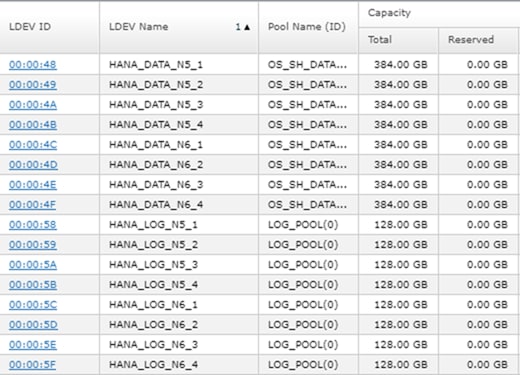
3. Initialize all LUNs beside the one hosting the operating system so LVM can access them.
pvcreate -ff -y /dev/mapper/360060e8012ccbc005040ccbc00000048 /dev/mapper/360060e8012ccbc005040ccbc00000049 /dev/mapper/360060e8012ccbc005040ccbc0000004a /dev/mapper/360060e8012ccbc005040ccbc0000004b
pvcreate -ff -y /dev/mapper/360060e8012ccbc005040ccbc00000058 /dev/mapper/360060e8012ccbc005040ccbc00000059 /dev/mapper/360060e8012ccbc005040ccbc0000005a /dev/mapper/360060e8012ccbc005040ccbc0000005b
4. Create volume groups from the physical volumes. Volume group naming differs between Scale-Up and Scale-Out installations.
- For SAP HANA Scale-Up use the volume group names vgdata, vglog, vgshared.
- For SAP HANA Scale-Out use the volume group names vgdata0{1|2|3|4} and vglog0{1|2|3|4} for a 4-node scale-out environment with 4 worker nodes.
vgcreate vgdata01 /dev/mapper/360060e8012ccbc005040ccbc00000048 /dev/mapper/360060e8012ccbc005040ccbc00000049 /dev/mapper/360060e8012ccbc005040ccbc0000004a /dev/mapper/360060e8012ccbc005040ccbc0000004b
vgcreate vglog01 /dev/mapper/360060e8012ccbc005040ccbc00000058 /dev/mapper/360060e8012ccbc005040ccbc00000059 /dev/mapper/360060e8012ccbc005040ccbc0000005a /dev/mapper/360060e8012ccbc005040ccbc0000005b
![]() To create other volume groups, use the same syntax, exchanging the volume group name as well as the physical disks or LUNs.
To create other volume groups, use the same syntax, exchanging the volume group name as well as the physical disks or LUNs.
5. Create a logical volume group for each volume group available:
lvcreate -y -n lvdata vgdata01 -l 100%FREE --stripesize 1024 -i4 /dev/mapper/360060e8012ccbc005040ccbc00000048 /dev/mapper/360060e8012ccbc005040ccbc00000049 /dev/mapper/360060e8012ccbc005040ccbc0000004a /dev/mapper/360060e8012ccbc005040ccbc0000004b
# lvcreate -y -n lvlog vglog01 -l 100%FREE --stripesize 1024 -i4 /dev/mapper/360060e8012ccbc005040ccbc00000058 /dev/mapper/360060e8012ccbc005040ccbc00000059 /dev/mapper/360060e8012ccbc005040ccbc0000005a /dev/mapper/360060e8012ccbc005040ccbc0000005b
![]() To create other logical volume groups, use the same syntax, exchanging the volume group name as well as the physical disks or LUNs.
To create other logical volume groups, use the same syntax, exchanging the volume group name as well as the physical disks or LUNs.
6. Construct a XFS file system on each logical volume:
mkfs.xfs -f /dev/mapper/vgdata01-lvdata
mkfs.xfs -f /dev/mapper/vglog01-lvlog
7. Confirm the volumes are visible on each host:
lvs
LV VG Attr LSize Pool …
root system -wi-ao---- 60.00g
swap system -wi-ao---- 2.00g
lvdata vgdata01 -wi-a----- 1.50t
lvdata vgdata02 -wi-a----- 1.50t
lvlog vglog01 -wi-a----- 511.98g
lvlog vglog02 -wi-a----- 511.98g
8. Create mount directories for the data, log, and HANA shared file systems:
mkdir -p -m 755 /hana/data
mkdir -p -m 755 /hana/log
mkdir -p -m 755 /hana/shared
SAP HANA Scale-Up
1. Add the following entries to /etc/fstab:
# HANA Volume
/dev/mapper/vgshared-lvshared /hana/shared xfs inode64,nobarrier 0 0
/dev/mapper/vgdata-lvdata /hana/data xfs inode64,nobarrier 0 0
/dev/mapper/vglog-lvlog /hana/log xfs inode64,nobarrier 0 0
2. Use the following command to mount the file systems from /etc/fstab:
mount -a
SAP HANA Scale-Out
1. Persist the HANA shared volume only and add the following entry to /etc/fstab:
# HANA Volume
192.168.110.40:/hana_shared_10 /hana/shared nfs \\ vers=3,proto=tcp,hard,intr,timeo=600,retrans=2,wsize=65536,rsize=65536 0 0
2. Use the following command to mount the file systems from /etc/fstab:
mount -a
![]() SAP HANA Scale-Out uses the SAP HANA storage API to manage the HANA data and log volume. Do not add the data and log volume groups to /etc/fstab.
SAP HANA Scale-Out uses the SAP HANA storage API to manage the HANA data and log volume. Do not add the data and log volume groups to /etc/fstab.
Persistent Memory Configuration
The utility ipmctl is used for configuring and managing Intel Optane DC persistent memory modules (DCPMM) and the ndctl utility library is required for managing the libnvdimm (non-volatile memory device) sub-system in the Linux kernel.
To configure Intel Persistent Memory using host tools, follow these steps:
1. SSH to the server as root.
2. Enable extra packages for the ndctl utility or any other dependencies:
subscription-manager repos --enable "rhel-*-optional-rpms" --enable "rhel-*-extras-rpms" --enable "rhel-ha-for-rhel-*-server-rpms"
3. Install the ndctl utility:
yum install ndctl ndctl-libs ndctl-devel libsafec rubygem-asciidoctor
…
Dependencies Resolved
=============================================================================
Package Arch Version Repository Size
=============================================================================
Installing:
ndctl x86_64 62-1.el7 rhel-7-server-rpms 122 k
ndctl-devel x86_64 62-1.el7 rhel-7-server-e4s-optional-rpms 21 k
ndctl-libs x86_64 62-1.el7 rhel-7-server-rpms 61 k
Installing for dependencies:
daxctl-libs x86_64 62-1.el7 rhel-7-server-rpms 26 k
4. Installation instructions to install the ipmctl tool:
cd /etc/yum.repos.d
wget https://copr.fedorainfracloud.org/coprs/jhli/ipmctl/repo/epel-7/jhli-ipmctl-epel-7.repo
wget https://copr.fedorainfracloud.org/coprs/jhli/safeclib/repo/epel-7/jhli-safeclib-epel-7.repo
yum install ipmctl
…
============================================================================
Package Arch Version Repository Size
============================================================================
Installing:
ipmctl x86_64 02.00.00.3446-1.el7
copr:copr.fedorainfracloud.org:jhli:ipmctl 70 k
Installing for dependencies:
libipmctl x86_64 02.00.00.3446-1.el7
copr:copr.fedorainfracloud.org:jhli:ipmctl 440 k
libsafec x86_64 03032018-2.0.g570fa5.el7
copr:copr.fedorainfracloud.org:jhli:safeclib 62 k
5. Confirm the persistent memory modules are discovered in the system and verify the software can communicate with them:
ipmctl show -dimm
DimmID | Capacity | HealthState | ActionRequired | LockState | FWVersion
==============================================================================
0x0001 | 252.4 GiB | Healthy | 0 | Disabled | 01.02.00.5367
0x0011 | 252.4 GiB | Healthy | 0 | Disabled | 01.02.00.5367
0x0021 | 252.4 GiB | Healthy | 0 | Disabled | 01.02.00.5367
0x0101 | 252.4 GiB | Healthy | 0 | Disabled | 01.02.00.5367
0x0111 | 252.4 GiB | Healthy | 0 | Disabled | 01.02.00.5367
0x0121 | 252.4 GiB | Healthy | 0 | Disabled | 01.02.00.5367
0x1001 | 252.4 GiB | Healthy | 0 | Disabled | 01.02.00.5367
0x1011 | 252.4 GiB | Healthy | 0 | Disabled | 01.02.00.5367
0x1021 | 252.4 GiB | Healthy | 0 | Disabled | 01.02.00.5367
0x1101 | 252.4 GiB | Healthy | 0 | Disabled | 01.02.00.5367
0x1111 | 252.4 GiB | Healthy | 0 | Disabled | 01.02.00.5367
0x1121 | 252.4 GiB | Healthy | 0 | Disabled | 01.02.00.5367
0x2001 | 252.4 GiB | Healthy | 0 | Disabled | 01.02.00.5367
0x2011 | 252.4 GiB | Healthy | 0 | Disabled | 01.02.00.5367
0x2021 | 252.4 GiB | Healthy | 0 | Disabled | 01.02.00.5367
0x2101 | 252.4 GiB | Healthy | 0 | Disabled | 01.02.00.5367
0x2111 | 252.4 GiB | Healthy | 0 | Disabled | 01.02.00.5367
0x2121 | 252.4 GiB | Healthy | 0 | Disabled | 01.02.00.5367
0x3001 | 252.4 GiB | Healthy | 0 | Disabled | 01.02.00.5367
0x3011 | 252.4 GiB | Healthy | 0 | Disabled | 01.02.00.5367
0x3021 | 252.4 GiB | Healthy | 0 | Disabled | 01.02.00.5367
0x3101 | 252.4 GiB | Healthy | 0 | Disabled | 01.02.00.5367
0x3111 | 252.4 GiB | Healthy | 0 | Disabled | 01.02.00.5367
0x3121 | 252.4 GiB | Healthy | 0 | Disabled | 01.02.00.5367
6. Create the goal:
ipmctl create -goal
The following configuration will be applied:
SocketID | DimmID | MemorySize | AppDirect1Size | AppDirect2Size
==================================================================
0x0000 | 0x0001 | 0.0 GiB | 252.0 GiB | 0.0 GiB
0x0000 | 0x0011 | 0.0 GiB | 252.0 GiB | 0.0 GiB
0x0000 | 0x0021 | 0.0 GiB | 252.0 GiB | 0.0 GiB
0x0000 | 0x0101 | 0.0 GiB | 252.0 GiB | 0.0 GiB
0x0000 | 0x0111 | 0.0 GiB | 252.0 GiB | 0.0 GiB
0x0000 | 0x0121 | 0.0 GiB | 252.0 GiB | 0.0 GiB
0x0001 | 0x1001 | 0.0 GiB | 252.0 GiB | 0.0 GiB
0x0001 | 0x1011 | 0.0 GiB | 252.0 GiB | 0.0 GiB
0x0001 | 0x1021 | 0.0 GiB | 252.0 GiB | 0.0 GiB
0x0001 | 0x1101 | 0.0 GiB | 252.0 GiB | 0.0 GiB
0x0001 | 0x1111 | 0.0 GiB | 252.0 GiB | 0.0 GiB
0x0001 | 0x1121 | 0.0 GiB | 252.0 GiB | 0.0 GiB
0x0002 | 0x2001 | 0.0 GiB | 252.0 GiB | 0.0 GiB
0x0002 | 0x2011 | 0.0 GiB | 252.0 GiB | 0.0 GiB
0x0002 | 0x2021 | 0.0 GiB | 252.0 GiB | 0.0 GiB
0x0002 | 0x2101 | 0.0 GiB | 252.0 GiB | 0.0 GiB
0x0002 | 0x2111 | 0.0 GiB | 252.0 GiB | 0.0 GiB
0x0002 | 0x2121 | 0.0 GiB | 252.0 GiB | 0.0 GiB
0x0003 | 0x3001 | 0.0 GiB | 252.0 GiB | 0.0 GiB
0x0003 | 0x3011 | 0.0 GiB | 252.0 GiB | 0.0 GiB
0x0003 | 0x3021 | 0.0 GiB | 252.0 GiB | 0.0 GiB
0x0003 | 0x3101 | 0.0 GiB | 252.0 GiB | 0.0 GiB
0x0003 | 0x3111 | 0.0 GiB | 252.0 GiB | 0.0 GiB
0x0003 | 0x3121 | 0.0 GiB | 252.0 GiB | 0.0 GiB
Do you want to continue? [y/n] y
7. Reboot the server for the new memory allocations.
8. Verify the regions created:
ipmctl show -region
SocketID | ISetID | Persistent | Capacity | FreeCapacity | HealthState
| | MemoryType | | |
================================================================================
0x0000 | 0xd7…9c2ccc | AppDirect | 1512.0 GiB | 0.0 GiB | Healthy
0x0001 | 0xfb…9b2ccc | AppDirect | 1512.0 GiB | 0.0 GiB | Healthy
0x0002 | 0xc6…af2ccc | AppDirect | 1512.0 GiB | 0.0 GiB | Healthy
0x0003 | 0x68…9f2ccc | AppDirect | 1512.0 GiB | 0.0 GiB | Healthy
9. Create a name space for each region; on a server with a total of 4 CPU invoke the command four times. For two socket systems invoke the command two times:
ndctl create-namespace
10. List the active name spaces previously created:
ndctl list
[
{
"dev":"namespace1.0",
"mode":"fsdax",
"map":"dev",
"size":1598128390144,
"uuid":"f722c877-97da-48b0-b18e-dcd0842a633b",
"blockdev":"pmem1"
},
{
"dev":"namespace3.0",
"mode":"fsdax",
"map":"dev",
"size":1598128390144,
"uuid":"a87f5c10-e71a-40d5-8264-99a25fe93b72",
"blockdev":"pmem3"
},
{
"dev":"namespace0.0",
"mode":"fsdax",
"map":"dev",
"size":1598128390144,
"uuid":"3677e9f3-6536-4a15-902d-42ffb0182500",
"blockdev":"pmem0"
},
{
"dev":"namespace2.0",
"mode":"fsdax",
"map":"dev",
"size":1598128390144,
"uuid":"549b567c-4f01-4831-8a6f-877c8f672d01",
"blockdev":"pmem2"
}
]
11. Create a file system and mount the persistent memory modules:
mkfs -t xfs -f /dev/pmem0
mkfs -t xfs -f /dev/pmem1
mkfs -t xfs -f /dev/pmem2
mkfs -t xfs -f /dev/pmem3
mkdir -p /hana/pmem/nvmem0
mkdir -p /hana/pmem/nvmem1
mkdir -p /hana/pmem/nvmem2
mkdir -p /hana/pmem/nvmem3
mount -t xfs -o dax /dev/pmem0 /hana/pmem/nvmem0
mount -t xfs -o dax /dev/pmem1 /hana/pmem/nvmem1
mount -t xfs -o dax /dev/pmem2 /hana/pmem/nvmem2
mount -t xfs -o dax /dev/pmem3 /hana/pmem/nvmem3
12. Add the mount points to the /etc/fstab file to make them permanent:
vi /etc/fstab
/dev/pmem0 /hana/pmem/nvmem0 xfs rw,relatime,attr2,dax,inode64,noquota 0 0
/dev/pmem1 /hana/pmem/nvmem1 xfs rw,relatime,attr2,dax,inode64,noquota 0 0
/dev/pmem2 /hana/pmem/nvmem2 xfs rw,relatime,attr2,dax,inode64,noquota 0 0
/dev/pmem3 /hana/pmem/nvmem3 xfs rw,relatime,attr2,dax,inode64,noquota 0 0
SAP HANA Installation
All version specific SAP installation and administration documentation is available from the SAP HANA Help portal: https://help.sap.com/hana. Please refer to the official SAP documentation which describes the different SAP HANA installation options.
![]() Review the latest changes in the Important SAP Notes section.
Review the latest changes in the Important SAP Notes section.
SAP HANA 2.0 Installation
The official SAP documentation describes in detail how to install the HANA software and all of the required components. For SAP HANA Scale-Up installations the required file systems are already mounted when the installation starts different to Scale-Out installations when the HANA data and log volumes are not mounted upfront. SAP HANA includes a ready-to-use storage connector client to manage fibre channel attached devices with native multipath. This enables host auto-failover on block storage level which is required for a successful failover to a standby host.
The fcCLient/fcClientLVM implementation uses standard Linux commands, such as multipath and sg_persist. It is responsible mounting the SAP HANA data and log volumes and implements the fencing mechanism during a host failover by means of SCSI-3 persistent reservations.
Before starting the SAP HANA Scale-Out installation some preparation steps are required before the SAP HANA installation can start.
Passwordless Authentication
To enable SSH access via public key authentication to access all SAP HANA Scale-Out servers without entering their root password, follow these steps:
1. On the first SAP HANA server create as root user an SSH key:
ssh-keygen -t rsa
2. Copy the public key to the other nodes:
ssh-copy-id root@<hostname {2|3|4}>
You will be prompted to enter the root password. Verify the login works password less afterwards.
Prepare SAP Storage Connector API Configuration File
Prepare a configuration file the SAP Storage Connector API will use during the installation process. Use the same file name. The file is not required any longer post installation.
vi /tmp/hana_install/global.ini
[communication]
listeninterface = .global
[persistence]
basepath_datavolumes = /hana/data/ANA
basepath_logvolumes = /hana/log/ANA
[storage]
ha_provider = hdb_ha.fcClientLVM
partition_*_*__prtype = 5
partition_1_log__lvmname = vglog01-lvlog
partition_1_data__lvmname = vgdata01-lvdata
partition_2_log__lvmname = vglog02-lvlog
partition_2_data__lvmname = vgdata02-lvdata
Install SAP HANA Software
Install SAP HANA on the master node, typically <hostname 1> and specify the required passwords and parameters. To install the SAP HANA software, follow these steps:
1. Extract the SAP HANA Platform software and change to the folder HDB_LCM_Linux_X86_64:
./hdblcm --action install --components=server,client --install_hostagent \
--number 00 --sapmnt=/hana/shared --sid=ANA --storage_cfg=/tmp/hana_install \
--hostname=cishana01 --certificates_hostmap=cishana01=hana001
2. Using <sidadm> stop SAP HANA and update the global.ini configuration file:
vi /usr/sap/<SID>/SYS/global/hdb/custom/config/global.ini
[communication]
listeninterface = .global
tcp_backlog = 2048
[fileio]
max_parallel_io_requests = 256
max_submit_batch_size = 64
size_kernel_io_queue = 512
async_read_submit = on
async_write_submit_blocks = all
min_submit_batch_size = 16
async_write_submit_active = on
[internal_hostname_resolution]
192.168.220.101 = cishana01i
192.168.220.102 = cishana02i
192.168.220.103 = cishana03i
192.168.220.104 = cishana04i
[multidb]
mode = multidb
database_isolation = low
singletenant = yes
[persistence]
basepath_datavolumes = /hana/data/ANA
basepath_logvolumes = /hana/log/ANA
[storage]
ha_provider = hdb_ha.fcClientLVM
partition_*_*__prtype = 5
partition_1_data__lvmname = vgdata01-lvdata
partition_1_log__lvmname = vglog01-lvlog
partition_2_data__lvmname = vgdata02-lvdata
partition_2_log__lvmname = vglog02-lvlog
partition_3_data__lvmname = vgdata03-lvdata
partition_3_log__lvmname = vglog03-lvlog
[system_information]
usage = test
[trace]
ha_fcclientlvm = info
![]() (Optional) Change the listeninterface parameter to .internal right away or do after the installation is complete.
(Optional) Change the listeninterface parameter to .internal right away or do after the installation is complete.
3. Using <sidadm> start SAP HANA again.
4. Using the root user ssh to the next Scale-Out worker node and change to folder: /hana/shared/<SID>/global/hdb/install/bin
5. Install a worker node using the following command syntax:
./hdbaddhost --install_hostagent --sapmnt=/hana/shared --role=worker --hostname=<hostname 2|3> --storage_partition=2
6. If applicable, install a standby node using the following command syntax:
./hdbaddhost --install_hostagent --sapmnt=/hana/shared --role=standby --hostname=<hostname 4>
SAP HANA 2.0 Parameters
Configure file I/O Recommended Parameters
The following file I/O configuration parameters are recommended to enhance the SAP HANA database behavior for Hitachi VSP enterprise storage. Define the parameters in the [fileio] section of the SAP HANA global.ini file.
Changes to these parameters require a restart of SAP HANA services:
[fileio]
max_parallel_io_requests = 512
max_submit_batch_size = 384
size_kernel_io_queue = 1024
async_read_submit = on
async_write_submit_blocks = all
min_submit_batch_size = 16
async_write_submit_active = on
Configure the Base Path to Use Persistent Memory
The directory that SAP HANA uses as its base path must point to the XFS file system. Define the base path location with the configuration parameter basepath_persistent_memory_volumes in the [persistence] section of the SAP HANA global.ini file. This section can contain multiple locations separated by semicolons.
Changes to this parameter require a restart of SAP HANA services:
[persistence]
basepath_datavolumes = /hana/data/<SID>
basepath_logvolumes = /hana/log/<SID>
basepath_persistent_memory_volumes = /hana/pmem/nvmem0;/hana/pmem/nvmem1;/hana/pmem/nvmem2;/hana/pmem/nvmem3
SAP HANA Scale-Out Related Parameters
For SAP HANA Scale-Out configurations we use the SAP HANA Storage API connector to mount or umount the SAP HANA data and log volume. This will enable the possibility of having a SAP HANA standby host while SAP HANA takes care of the volume failover in this high availability configuration. Add additional partitions accordingly depending the number of worker nodes in the SAP HANA Scale-Out environment.
Define the following parameters in the [storage] and [trace] section of the SAP HANA global.ini file.
Changes to these parameters require a restart of SAP HANA services:
[storage]
ha_provider = hdb_ha.fcClientLVM
partition_*_*__prtype = 5
partition_*_*__mountoptions = -t xfs
partition_1_data__lvmname = vgdata01-lvdata
partition_1_log__lvmname = vglog01-lvlog
partition_2_data__lvmname = vgdata02-lvdata
partition_2_log__lvmname = vglog02-lvlog
[trace]
ha_fcclientlvm = info
Allow the internal host name resolution and configure the parameters in the [communication] and [internal_hostname_resolution] sections of the SAP HANA global.ini file. Review the recommendations in the SAP HANA help portal as well: https://help.sap.com/viewer/742945a940f240f4a2a0e39f93d3e2d4/2.0.02/en-US/eccef06eabe545e68d5019bcb6d8e342.html.
Changes to these parameters require a restart of SAP HANA services:
[communication]
listeninterface = .internal
[internal_hostname_resolution]
192.168.93.101 = <var_os_host_name_node_1>
192.168.93.102 = <var_os_host_name_node_2>
Cisco Intersight gives manageability and visibility to multiple UCS domains through a common interface, regardless of location. The Base addition is available for UCSM starting at release 3.2(1) at no additional cost.
To add the Cisco UCS Fabric Interconnects into Intersight, follow this step:
1. Connect to https://www.intersight.com:

Prerequisites
The following prerequisites are necessary to setup access to Cisco Intersight:
· An account on cisco.com.
· A valid Cisco Intersight account. This can be created by navigating to https://intersight.com and following the instructions for creating an account. The account creation requires at least one device to be registered in Intersight and requires Device ID and Claim ID information from the device. See Collecting Information From Cisco UCS Domain for an example of how to get Device ID and Claim ID from Cisco UCS Fabric Interconnect devices.
· Valid License on Cisco Intersight – see Cisco Intersight Licensing section below for more information.
· Cisco UCS Fabric Interconnects must be able to do a DNS lookup to access Cisco Intersight.
· Device Connectors on Fabric Interconnects must be able to resolve svc.ucs-connect.com.
· Allow outbound HTTPS connections (port 443) initiated from the Device Connectors on Fabric Interconnects to Cisco Intersight. HTTP Proxy is supported.
Setup Information
To setup access to Cisco Intersight, the following information must be collected from the Cisco UCS Domain. The deployment steps provided in the following sections will show how to collect this information.
· Device ID
· Claim Code
Cisco Intersight Licensing
Cisco Intersight is offered in two editions:
· Base license which is free to use, and offers a large variety of monitoring, inventory and reporting features.
· Essentials license, at an added cost but provides advanced monitoring, server policy and profile configuration, firmware management, virtual KVM features, and more. A 90-day trial of the Essentials license is available for use as an evaluation period.
New features and capabilities will be added to the different licensing tiers in future release.
Deployment Steps
To setup access to Cisco Intersight from a Cisco UCS domain, follow the steps outlined in this section.
Connect to Cisco Intersight
To connect and access Cisco Intersight, follow these steps:
1. Use a web browser to navigate to Cisco Intersight at https://intersight.com/.
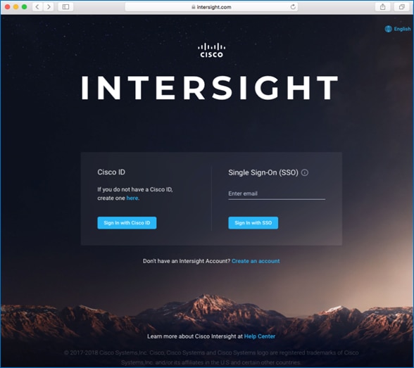
2. Login with a valid cisco.com account or single sign-on using your corporate authentication.
Collect Information from UCS Domain
To collect information from Cisco UCS Fabric Interconnects to setup access to Cisco Intersight, follow these steps:
1. Use a web browser to navigate to the Cisco UCS Manager GUI. Login using the admin account.
2. From the left navigation menu, select the Admin icon.
3. From the left navigation pane, select All > Device Connector.
4. In the right window pane, for Intersight Management, click Enabled to enable Intersight management.
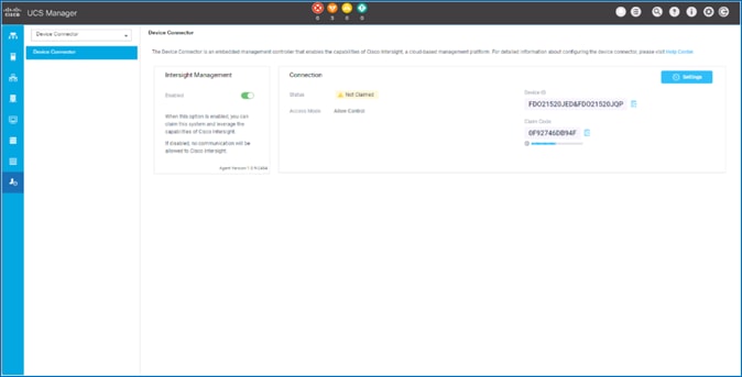
5. From the Connection section, copy the Device ID and Claim ID information. This information will be required to add this device to Cisco Intersight.
6. (Optional) Click Settings to change Access Mode and to configure HTTPS Proxy.
Add Cisco UCS Domain to Cisco Intersight
To add Cisco UCS Fabric Interconnects to Cisco Intersight to manage the UCS domain, follow these steps:
1. From Cisco Intersight, in the left navigation menu, select Devices.
2. Click Claim a New Device.
3. In the Claim a New Device pop-up window, paste the Device ID and Claim Code collected in the previous section.
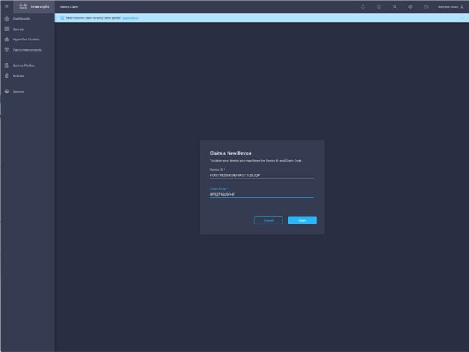
4. Click Claim.
On Cisco Intersight, the newly added UCS domain should now have a Status of Connected.
On Cisco UCS Manager, the Device Connector should now have a Status of Claimed.
Dashboard will present an overview of the managed UCS domains as shown below:
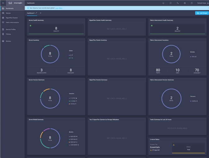
Introduction
AppDynamics is an Application Performance Monitoring (APM) Platform that helps you to understand and optimize the performance of your business, from its software to infrastructure to business journeys.
The AppDynamics APM Platform enables you to monitor and manage your entire application-delivery ecosystem, from the mobile app or browser client request through your network, backend databases and application servers and more. AppDynamics APM gives you a single view across your application landscape, letting you quickly navigate from the global perspective of your distributed application right down to the call graphs or exception reports generated on individual hosts.
AppDynamics has an agent-based architecture. Once our agents are installed it gives you a dynamic flow map or topography of your application. It uses the concept of traffic lights to indicate the health of your application (green is good, yellow is slow and red indicates potential issues) with dynamic baselining. AppDynamics measures application performance based on business transactions which essentially are the key functionality of the application. When the application deviates from the baseline AppDynamics captures and provides deeper diagnostic information to help be more proactive in troubleshooting and reduce the MTTR (mean time to resolution).
SAP Landscape Monitoring
AppDynamics has a one of its kind ABAP agent for monitoring SAP ABAP systems. We have comprehensive coverage of the SAP landscape with our ABAP, Java, .net and Server visibility agents. In addition, Datavard Insights extends the AppDynamics for SAP solution with system-level monitoring for the overall SAP systems and SAP HANA databases. While AppDynamics agents provides transaction-level visibility, Datavard Insights collects performance metrics, logs and events, including processes outside of the user business transactions, such as background jobs or IDocs processing.
The complex and proprietary nature of SAP applications makes it difficult to diagnose issues. AppDynamics allows enterprises to instrument SAP applications, monitor performance, and understand the root cause of performance bottlenecks.
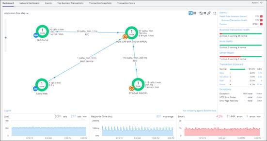
Trial Registration
To register for a free trial, follow these steps:
1. Connect to https://www.appdynamics.com/free-trial/
2. Provide the details to sign up for a free trial utilizing an AppDynamics SaaS controller.

3. Once the AppDynamics SaaS Controller has been provisioned, you will receive an email with the information you need for you to login to the Controller.
4. You can download the Java Agent and the Server Visibility Agent directly from the Controller.
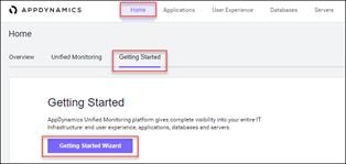
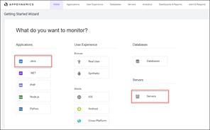
5. You can use the email and password you provided to sign up for the trial to login to the agent download site at the URL listed below and download the ABAP Agent:
https://download.appdynamics.com
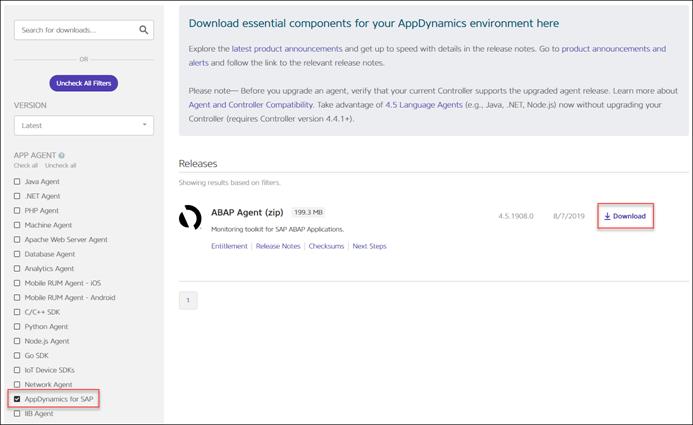
Agent Installation
AppDynamics has several types of agents to monitor different language applications to user Experience to Infrastructure monitoring. Based on the SAP landscape and the underlying technology of the SAP systems the agents are installed.
The most frequently installed agents are:
· Java Agent - For Java based SAP Systems
· ABAP Agent - For ABAP based SAP systems
· Server Visibility Agent - Provides extended hardware metrics and Service Availability Monitoring
Prerequisites
To verify the supported SAP environments, go to:
https://docs.appdynamics.com/display/SAP/SAP+Supported+Environments
Java Agent Installation
The Java Agent must be installed on SAP Java application servers (e.g. Enterprise Portal and PO application servers).
To install the Java Agent, follow these high-level steps:
1. Ensure you are logged into the host server as the appropriate <sidadm> OS user.
2. Create the permanent installation directory for the agent.
3. Unzip the file in the permanent directory (for example, /usr/sap/appdyn/app).
4. Change the permissions on the contents of the agents' installation directory to give full read/write privileges at the owner and group levels.
5. Edit the configuration file in the agent installation directory to configure the agent to connect to the controller, provide the identity of the JVM, and so on.
Configuring AppDynamics Java Agent in SAP
7. Restart the SAP JVM for the settings to take effect.
8. Validate the Java Agent is reporting to the controller by logging into the controller UI.
For more information, go to Install the AppDynamics Java Agent.
ABAP Agent Installation
The ABAP Agent needs to be installed on the SAP servers utilizing the ABAP stack. The installation requires these four main steps:
· Copy and unzip the ABAP Agent
· Import the ABAP Agent Transports
· Configure ABAP Agent and Install HTTP SDK
· Activate Datavard Insight Collectors
1. Copy and unzip the ABAP Agent:
a. Ensure you are logged into the host server as the appropriate <sidadm> OS user
b. Copy the agent binary to a temporary directory on the server
c. Unzip the file into a temporary directory
d. Change the permissions on the contents of the agents' installation directory to give full read/write privileges at the owner and group levels
2. Import the ABAP Agent Transports:
![]() There are different versions of data files and cofiles within the ABAP agents’ unzipped directory structure. The specific location of the appropriate files in the agents’ directory structure to use will depend on the version of NetWeaver in use. For more information, go to the related documentation Install on SAP NetWeaver Systems.
There are different versions of data files and cofiles within the ABAP agents’ unzipped directory structure. The specific location of the appropriate files in the agents’ directory structure to use will depend on the version of NetWeaver in use. For more information, go to the related documentation Install on SAP NetWeaver Systems.
a. The ABAP Agents data files and cofiles should be copied from the temporary directories where they were unzipped over to the appropriate transport directories for the SAP module in question.
§ For example, for ECC you could copy the transports to "/usr/sap/trans/ECC2/cofiles" and "/usr/sap/trans/ECC2/data".
b. Set the permissions on the cofiles and data files to allow read/write access at the owner and group levels.
c. Login to the SAP system, execute transaction STMS:
§ Go to the import queue of the system where you want to install the ABAP agent.
§ Select "Extras > Other Requests > Add" from the menu bar and add the vendor transports to the import queue one at a time.
d. Import the transports in the appropriate order:
§ The import order of the transports is specified in the “readme.txt” file of the ABAP Agent subdirectory that is specific to the version of NetWeaver in use.
§ For more information, go to: Install on SAP NetWeaver Systems
§ Make sure that when selecting the "Execution" tab in the "Import Transport Request" pop-up dialog box to select the option "Synchronous". When selecting the "Options" tab, put a checkmark next to "Ignore Invalid Component Version".
3. Configure ABAP Agent and install HTTP SDK:
![]() The following steps assume that your Linux hosts have glibc 2.5+ installed to allow for the automatic HTTP SDK installation. For more information, go to: Supported SAP Operating Systems and Installing HTTP SDK Automatically.
The following steps assume that your Linux hosts have glibc 2.5+ installed to allow for the automatic HTTP SDK installation. For more information, go to: Supported SAP Operating Systems and Installing HTTP SDK Automatically.
a. Login to the SAP system and execute transaction "/DVD/APPD_CUST".
b. Switch to edit mode.
c. Fill in the fields on the screen to configure the agent to connect to the controller, SDK settings, and Analytics API settings.
d. Click Activate integration.
e. Click SDK Installation. This will take you to the AppDynamics HTTP SDK Installation Manager screen.
f. Select Edit > Change Directory.
g. Enter the path that was used for the agents' permanent base install directory (for example, /usr/sap/appdyn) in the field displayed in the pop-up dialog box shown below and then click OK.
h. Click Install SDK.
i. Click the green checkmark to exit the screen and return to the AppDynamics settings screen.
j. Click Status. This will take you to the AppDynamics status check screen.
k. Click Start to start the HTTP SDK proxy on each SAP app server.
Activate Datavard Insight Collectors
Datavard Insights collect detailed performance data for an SAP system. It uses collector jobs that run as periodic background processes in the SAP system. These jobs must be scheduled to run.
To view the related documentation, go to:
Performance Collector Settings
Mapping Between AppDynamics Metrics and Datavard Insights KPIs
Server Visibility Agent Installation
The Server Visibility Agent must be installed on every application server and central services server that will be monitored.
To install the Server Visibility agent, follow these high-level steps:
1. Ensure you are logged into the host server as the appropriate <sidadm> OS user.
2. Create the permanent installation directory for the agent.
3. Unzip the file in the permanent directory (for example, /usr/sap/appdyn/machine).
4. Change the permissions on the contents of the agents' installation directory to give full read/write privileges at the owner and group levels.
5. Edit the configuration files in the agent installation directory to configure the agent to connect to the controller, provide the identity of the host, and so on.
6. Start the server visibility agent with the script provided in the agents’ bin directory.
7. Validate the server visibility is reporting to the controller by logging into the controller UI.
For more information, go to Install the AppDynamics Server Visibility Agent.
Environment Variables
Table 25 Nexus Switch Configuration Variables
| Variable |
Description |
Customer Implementation Value |
| <var_nexus_admin_pw> |
Admin password of the Nexus switch |
|
| <var_nexus_A_hostname> |
Cisco Nexus 9336C-FX2-A host name |
|
| <var_nexus_A_mgmt_ip> |
Out-of-band Cisco Nexus 9336C-FX2-A management IP address |
|
| <var_nexus_B_hostname> |
Cisco Nexus 9336C-FX2-B host name |
|
| <var_nexus_B_mgmt_ip> |
Out-of-band Cisco Nexus 9336C-FX2-B management IP address |
|
| <var_oob_mask> |
Out-of-band management network netmask |
|
| <var_oob_gateway> |
Out-of-band management network default gateway |
|
| <var_oob_ntp_ip> |
Out-of-band NTP server IP address |
|
| <var_nexus_vpc_domain_id> |
Unique Cisco Nexus switch VPC domain ID for Cisco Nexus 9336C-FX2 Switch pair |
|
| <var_mgmt_vlan_id> |
Management Network VLAN ID |
|
| <var_backup_vlan_id> |
Backup Network for HANA VLAN ID |
|
| <var_client_vlan_id> |
Client Network for HANA VLAN ID |
|
| <var_appserver_vlan_id> |
Application Server Network for HANA VLAN ID |
|
| <var_datasource_vlan_id> |
Data source Network for HANA VLAN ID |
|
| <var_replication_vlan_id> |
Replication Network for HANA VLAN ID |
|
| <var_internal_vlan_id> |
Internal Network for HANA Scale-Out VLAN ID |
|
| <var_nfsshared_vlan_id> |
Shared network for HANA Scale-Out VLAN ID |
|
Table 26 Cisco UCS Configuration Variables
| Variable |
Description |
Customer Implementation Value |
| <var_ucs_admin_pw> |
Admin password for the UCS Manager |
|
| <var_ucs_clustername> |
Cisco UCS Manager cluster host name |
|
| <var_ucsa_mgmt_ip> |
Cisco UCS 6332-16UP-A out-of-band management IP address |
|
| <var_ucsb_mgmt_ip> |
Cisco UCS 6332-16UP-B out-of-band management IP address |
|
| <var_ucs_cluster_ip> |
Cisco UCS Manager cluster IP address |
|
| <var_global_ntp_server_ip> |
NTP server IP address |
|
| <var_dns_domain_name> |
DNS domain name |
|
| <var_nameserver_ip> |
DNS server IP(s) |
|
Table 27 MDS Switch Configuration Variables
| Variable |
Description |
Customer Implementation Value |
| <var_mds_admin_pw> |
Admin password of the MDS switch |
|
| <var_mds-a_name> |
Cisco MDS A hostname |
|
| <var_mds-a_mgmt_ip> |
Cisco MDS A Management IP Address |
|
| <var_mds-b_name> |
Cisco MDS B hostname |
|
| <var_mds-b_mgmt_ip> |
Cisco MDS B Management IP Address |
|
| <var_fc-pc_a_id> / <var_fabric-A_vsan_id> |
Fiber Channel - Port Channel ID for Cisco MDS A |
|
| <var_fc-pc_b_id> / <var_fabric-B_vsan_id> |
Fiber Channel - Port Channel ID for Cisco MDS B |
|
| <var_san_a_id> |
VSAN ID for Cisco MDS A |
|
| <var_san_b_id> |
VSAN ID for Cisco MDS B |
|
Table 28 Hitachi Storage Variables
| Variable |
Description |
Customer Implementation Value |
| <var_hitachi_svp_ip> |
Out-of-band management IP for Hitachi storage management network |
|
| <var_hitachi_controller-1_mgmt_ip> |
Out-of-band management IP for Hitachi storage Controller 1 |
|
| <var_hitachi_controller-2_mgmt_ip> |
Out-of-band management IP for Hitachi storage Controller 2 |
|
| <var_hitachi_svp_ip> |
Hitachi SVP management IP |
|
Table 29 Operating System Variables
| Variable |
Description |
Customer Implementation Value |
| <var_os_root_pw> |
Linux root password |
|
| <var_os_host_name> |
Hostname of the UCS server |
|
| <var_os_domain_name> |
Domain name of the UCS server |
|
| <var_os_dns_server_1> |
DNS server 1 |
|
| <var_os_dns_server_2> |
DNS server 2 |
|
| <var_os_default_ipv4_gateway> |
IP4 Gateway |
|
| <SID> |
SAP System Identification for the SAP HANA Platform |
|
Certified SAP HANA Hardware Directory
Cisco UCS Server https://www.sap.com/dmc/exp/2014-09-02-hana-hardware/enEN/intel-systems.html#categories=Cisco%20Systems%20Inc.
Hitachi Enterprise Storage https://www.sap.com/dmc/exp/2014-09-02-hana-hardware/enEN/enterprise-storage.html#categories=certified%23Hitachi
SAP HANA TDI Documentation
· SAP HANA TDI: Overview
· SAP HANA TDI: FAQ
· SAP HANA TDI: Storage Requirements
· SAP HANA TDI: Network Requirements
Important SAP Notes
Read the following SAP Notes before you start the HANA installation. These SAP Notes contain the latest information about the installation, as well as corrections to the installation documentation.
The latest SAP Notes can be found here: https://service.sap.com/notes.
SAP HANA IMDB Related Notes
SAP Note 1514967 - SAP HANA: Central Note
SAP Note 1523337 - SAP HANA Database: Central Note
SAP Note 2000003 - FAQ: SAP HANA
SAP Note 1755396![]() - Released DT solutions for SAP HANA with disk replication
- Released DT solutions for SAP HANA with disk replication
SAP Note 1681092 - Support for multiple SAP HANA databases on a single SAP HANA appliance
Linux Related Notes
SAP Note 2235581 - SAP HANA: Supported Operating Systems
SAP Note 2684254 - SAP HANA DB: Recommended OS settings for SLES 15 / SLES for SAP Applications 15
SAP Note 2578899 - SUSE LINUX Enterprise Server 15: Installation notes
SAP Note 1275776 - Linux: Preparing SLES for SAP environments
SAP Note 2382421- Optimizing the Network Configuration on HANA- and OS-Level
SAP Note 2002167 - Red Hat Enterprise Linux 7.x: Installation and Upgrade
SAP Note 2292690 - SAP HANA DB: Recommended OS settings for RHEL 7
SAP Note 2009879 - SAP HANA Guidelines for RedHat Enterprise Linux (RHEL)
SAP Note 1731000![]() - Non-recommended configuration changes
- Non-recommended configuration changes
SAP Note 1829651![]() - Time zone settings in SAP HANA scale out landscapes
- Time zone settings in SAP HANA scale out landscapes
SAP Application Related Notes
SAP Note 1681092![]() - Support for multiple SAP HANA databases one HANA aka Multi SID
- Support for multiple SAP HANA databases one HANA aka Multi SID
SAP Note 2186744 - FAQ: SAP HANA Parameters
SAP Note 2493172 - SAP HANA Hardware and Cloud Measurement Tools
SAP Note 2399079 - Elimination of hdbparam in HANA 2
Cisco
MDS Best Practices: https://www.cisco.com/c/en/us/products/collateral/storage-networking/mds-9700-series-multilayer-directors/white-paper-c11-738426.html
Cisco MDS 9000 Series Interfaces Configuration Guide, Release 8.x: https://www.cisco.com/c/en/us/td/docs/switches/datacenter/mds9000/sw/8_x/config/interfaces/cisco_mds9000_interfaces_config_guide_8x.html
Nexus vPC Best Practices: https://www.cisco.com/c/dam/en/us/td/docs/switches/datacenter/sw/design/vpc_design/vpc_best_practices_design_guide.pdf
Cisco Nexus 9000 Series NX-OS Interfaces Configuration Guide, Release 7.x: https://www.cisco.com/c/en/us/td/docs/switches/datacenter/nexus9000/sw/7-x/interfaces/configuration/guide/b_Cisco_Nexus_9000_Series_NX-OS_Interfaces_Configuration_Guide_7x.html
Cisco UCS Best Practices: https://www.cisco.com/c/en/us/products/collateral/servers-unified-computing/ucs-manager/whitepaper_c11-697337.html
Cisco UCS Performance and Tuning: https://www.cisco.com/c/dam/en/us/products/collateral/servers-unified-computing/ucs-b-series-blade-servers/whitepaper_c11-740098.pdf
Cisco UCS for SAP HANA with Intel Optane DC Persistent Memory Module: https://www.cisco.com/c/dam/en/us/products/servers-unified-computing/ucs-b-series-blade-servers/whitepaper-c11-742627.pdf
Cisco UCS 6300 Spec Sheet https://www.cisco.com/c/dam/en/us/products/collateral/servers-unified-computing/ucs-b-series-blade-servers/6332-specsheet.pdf
Cisco UCS: Design Zone for SAP Applications (technical documentation)
Cisco UCS: Data Center Solutions for SAP (customer references)
Configure a Cisco AppDynamics Monitoring Solution for SAP Applications: https://www.cisco.com/c/en/us/solutions/collateral/data-center-virtualization/unified-computing/appd-sap-monitoring-wp.html
Hitachi Storage
Hitachi Virtual Storage Platform F Series:
Hitachi Virtual Storage Platform G Series:
SAP HANA Tailored Data Center Integration with Hitachi VSP F/G Storage Systems and SVOS RF
Hitachi Virtual Storage Platform E990
https://www.hitachivantara.com/en-us/products/storage/all-flash-hybrid-flash-storage/vsp-e990.html
SAP HANA TDI on Virtual Storage Platform E990 with Hitachi Storage Virtualization Operating System Reference Architecture:
Cisco and Hitachi Adaptive Solutions for SAP HANA TDI in a Direct-Attached Configuration with Hitachi Virtual Storage Platform E990
SAP HANA TDI on VSP 5000 Series with Hitachi Storage Virtualization Operating System RF Reference Architecture:
Joerg Wolters, Technical Marketing Engineer, Cisco Systems, Inc. (GmbH)
Joerg is a Technical Marketing Engineer and part of the Cisco UCS Solutions and Performance Group. Joerg has over six years of experience with SAP HANA on Cisco UCS platform. Joerg led the Cisco Solution Support for SAP HANA during the past five years. Currently, his focus is on developing and validating infrastructure best practices for SAP applications on Cisco UCS Servers, Cisco Nexus products and Storage technologies.
Acknowledgements
For their support and contribution to the design, validation, and creation of this Cisco Validated Design, the author would like to thank:
· Maximilian Weiß, Senior Solution Architect, Hitachi Vantara
· Dr. Stephan Kreitz, Master Solution Architect, Hitachi Vantara
 Feedback