Cisco UCS Integrated Infrastructure for Big Data and Analytics with MapR Data Platform
Available Languages

Cisco UCS Integrated Infrastructure for Big Data and Analytics with MapR Data Platform
Building a 28-Node Cluster with MapR
Last Updated: October 18, 2019

About the Cisco Validated Design Program
The Cisco Validated Design (CVD) program consists of systems and solutions designed, tested, and documented to facilitate faster, more reliable, and more predictable customer deployments. For more information, go to:
http://www.cisco.com/go/designzone.
ALL DESIGNS, SPECIFICATIONS, STATEMENTS, INFORMATION, AND RECOMMENDATIONS (COLLECTIVELY, "DESIGNS") IN THIS MANUAL ARE PRESENTED "AS IS," WITH ALL FAULTS. CISCO AND ITS SUPPLIERS DISCLAIM ALL WARRANTIES, INCLUDING, WITHOUT LIMITATION, THE WARRANTY OF MERCHANTABILITY, FITNESS FOR A PARTICULAR PURPOSE AND NONINFRINGEMENT OR ARISING FROM A COURSE OF DEALING, USAGE, OR TRADE PRACTICE. IN NO EVENT SHALL CISCO OR ITS SUPPLIERS BE LIABLE FOR ANY INDIRECT, SPECIAL, CONSEQUENTIAL, OR INCIDENTAL DAMAGES, INCLUDING, WITHOUT LIMITATION, LOST PROFITS OR LOSS OR DAMAGE TO DATA ARISING OUT OF THE USE OR INABILITY TO USE THE DESIGNS, EVEN IF CISCO OR ITS SUPPLIERS HAVE BEEN ADVISED OF THE POSSIBILITY OF SUCH DAMAGES.
THE DESIGNS ARE SUBJECT TO CHANGE WITHOUT NOTICE. USERS ARE SOLELY RESPONSIBLE FOR THEIR APPLICATION OF THE DESIGNS. THE DESIGNS DO NOT CONSTITUTE THE TECHNICAL OR OTHER PROFESSIONAL ADVICE OF CISCO, ITS SUPPLIERS OR PARTNERS. USERS SHOULD CONSULT THEIR OWN TECHNICAL ADVISORS BEFORE IMPLEMENTING THE DESIGNS. RESULTS MAY VARY DEPENDING ON FACTORS NOT TESTED BY CISCO.
CCDE, CCENT, Cisco Eos, Cisco Lumin, Cisco Nexus, Cisco StadiumVision, Cisco TelePresence, Cisco WebEx, the Cisco logo, DCE, and Welcome to the Human Network are trademarks; Changing the Way We Work, Live, Play, and Learn and Cisco Store are service marks; and Access Registrar, Aironet, AsyncOS, Bringing the Meeting To You, Catalyst, CCDA, CCDP, CCIE, CCIP, CCNA, CCNP, CCSP, CCVP, Cisco, the Cisco Certified Internetwork Expert logo, Cisco IOS, Cisco Press, Cisco Systems, Cisco Systems Capital, the Cisco Systems logo, Cisco Unified Computing System (Cisco UCS), Cisco UCS B-Series Blade Servers, Cisco UCS C-Series Rack Servers, Cisco UCS S-Series Storage Servers, Cisco UCS Manager, Cisco UCS Management Software, Cisco Unified Fabric, Cisco Application Centric Infrastructure, Cisco Nexus 9000 Series, Cisco Nexus 7000 Series. Cisco Prime Data Center Network Manager, Cisco NX-OS Software, Cisco MDS Series, Cisco Unity, Collaboration Without Limitation, EtherFast, EtherSwitch, Event Center, Fast Step, Follow Me Browsing, FormShare, GigaDrive, HomeLink, Internet Quotient, IOS, iPhone, iQuick Study, LightStream, Linksys, MediaTone, MeetingPlace, MeetingPlace Chime Sound, MGX, Networkers, Networking Academy, Network Registrar, PCNow, PIX, PowerPanels, ProConnect, ScriptShare, SenderBase, SMARTnet, Spectrum Expert, StackWise, The Fastest Way to Increase Your Internet Quotient, TransPath, WebEx, and the WebEx logo are registered trademarks of Cisco Systems, Inc. and/or its affiliates in the United States and certain other countries.
All other trademarks mentioned in this document or website are the property of their respective owners. The use of the word partner does not imply a partnership relationship between Cisco and any other company. (0809R)
© 2019 Cisco Systems, Inc. All rights reserved.
Table of Contents
Cisco UCS Integrated Infrastructure for Big Data and Analytics
Cisco UCS 6300 Series Fabric Interconnects
Cisco UCS C-Series Rack-Mount Servers
Cisco UCS Virtual Interface Cards
Cisco Intersight Cloud Based Management
MapR Enterprise-Grade Platform Services
Port Configuration on Fabric Interconnect
Server Configuration and Cabling for Cisco UCS C240 M5
Software Distributions and Versions
Cisco Unified Computing System Configuration
Configure Cisco UCS Fabric Interconnect
Configure Fabric Interconnects for a Cluster Setup
Configure Base Cisco Unified Computing System
Configure IP, UUID, Server, and MAC Pools
Set System class QoS and Jumbo Frame in Both the Cisco Fabric Interconnect
Create the Local Disk Configuration Policy
Configure and Create a Service Profile Template
Create Service Profile Template
Create Service Profile from Template
Install SUSE Linux Enterprise Server 12 SP3
Upgrade the Cisco Network Driver for VIC1387
Disable Transparent Huge Pages
Configure Data Drives on Data Nodes
Run the Cluster Verification Script
Node Types and Associated Services
Prepare Packages and Repositories
RPM Repositories for MapR Core Software
RPM Repositories for Hadoop Ecosystem Tools
Set Up and Run the MapR Installer
As the enterprises are expanding their lines of businesses, the data deluge from diverse data sources are creating new opportunities for business at the same time creating newer data management changes. Customers are looking for more enterprise-grade features where the core set of data services are designed to ensure exabyte-scale and high-performance while providing unmatched data protection, disaster recovery, security, and management services for disparate data types, including files, objects, tables, events, and more. Open APIs and support for containerization ensure broad distributed application access and seamless portability of applications across disparate environments.
Organizations want to maintain their status-quo and combine legacy and new technologies. They also want data to be made available to everyone in a secure, easy-to-use fashion. Essentially organizations need to do more with less. Data is stored on all layers in the stack, and there is no way to manage data as one digital asset independent of workloads, infrastructure, or applications. Therefore, Enterprises are embarking on data platform modernization to get ready to face the demands of modern-day business as new opportunities are created with the deluge of data from diverse data sources. As organizations adopt to modern data platforms at larger scale, aspects such as scale, compute, storage network, monitoring, and performance becomes essential as well. Enterprise applications in production requires scale, security, availability, and high-performance capabilities as well.
Cisco UCS Integrated Infrastructure for Big Data and Analytics enables the next-generation of big data architecture by providing simplified and centralized management, industry-leading performance, and a linearly scaling infrastructure and software platform. The configuration detailed in the document can be scaled to clusters of various sizes depending on the application demand. Up to 28 servers can be supported with no additional switching in a single Cisco UCS domain. Scaling beyond 28 servers can be implemented by interconnecting multiple Cisco UCS domains using Nexus 9000 Series switches or Cisco Application Centric Infrastructure (ACI), scalable to thousands of servers and to hundreds of petabytes of storage and managed from a single pane.
MapR Data Platform provides organizations with the enterprise-level functionality needed to take Big Data to production. This helps IT organizations manage the Data platforms by unleashing greater value from all your data in less time. The data struggle is real. Last-generation and even newer technologies for data platforms are limiting and lead to silos data across the organization, which hinder innovation, collaboration.
Together, Cisco UCS and MapR combine to create an industry leading modern data platforms to address today’s most challenging business to be agile to innovate and be market leading.
Introduction
With the evolving business needs, Applications have evolved from being monolithic to multi-tier to today’s connected network of distributed services woven together through microservices. As a result, organizations are faced with the challenge of data still being stored across all layers without a universal way to manage and access it. The data deluge and complexity of Big Data calls for a very clear need for a proven, dependable, high-performance platform for the ingestion, processing, storage and analysis of the data, as well as the seamless dissemination of the output, results and insights of the analysis.
The MapR Data Platform integrates the power of big data and Spark with global event streaming, real-time database capabilities and enterprise storage for developing and running innovative data applications. MapR was engineered for the data center with IT operations in mind. MapR enables big data applications using Spark and more to serve business-critical needs that cannot afford to lose data, must run on a 24x7 basis and require immediate recovery from node and site failures. The Cisco UCS Integrated Infrastructure for Big Data and Analytics and MapR Data Platform support these capabilities for the broadest set of applications from batch analytics to interactive querying and real-time streaming.
Solution
This CVD describes a scalable architecture and deployment procedures for the MapR Data Platform on the Cisco UCS Integrated Infrastructure for Big Data and Analytics.
This CVD implements the following:
· MapR Data Platform 6.1 on Cisco UCS Integrated Infrastructure for Big Data and Analytics
· Implementation is on Cisco UCS M5 Series Rack mount servers
· SUSE Linux Enterprise Server Operating System installation and post OS configurations for MapR
· GUI based Installation of MapR with MapR Installer
As one of the technology leaders in big Data, the MapR Data Platform distribution provides enterprise-class big data solutions that are fast to develop and easy to administer. With significant investment in critical technologies, MapR offers a complete data platform - a platform that is fully optimized for performance and scalability.
Deployed as part of a comprehensive data center architecture, the Cisco UCS Integrated Infrastructure for Big Data and Analytics with MapR fundamentally transforms the way that organizations do business with big data technology by delivering a powerful and flexible infrastructure that: increases business and IT agility, reduces total cost of ownership (TCO), and delivers exceptional return on investment (ROI) at scale.
The solution is built on the Cisco UCS Integrated Infrastructure for Big Data and Analytics and includes computing, storage, network and unified management capabilities to help companies manage the vast amount of data they collect today.
Cisco Unified Computing System infrastructure uses third generation Cisco UCS 6300 Series Fabric Interconnects and fifth generation (M5) Cisco UCS C-Series Rack Servers. This architecture is specifically designed for performance and linear scalability for big data workloads.
Audience
This document describes the architecture and deployment procedures for the MapR Data Platform on a 28 node Cisco UCS C240 M5 node cluster based on Cisco UCS Integrated Infrastructure for Big Data and Analytics. The intended audience of this document includes, but is not limited to, sales engineers, field consultants, professional services, IT managers, partner engineering and customers who want to deploy the MapR Data Platform on Cisco UCS Integrated Infrastructure for Big Data and Analytics.
Purpose of this Document
This document describes the architecture and deployment procedures for MapR 6.1.0 on a 28-node Cisco UCS C240 M5 cluster based on Cisco UCS Integrated Infrastructure for Big Data and Analytics.
Solution Summary
This CVD describes in detail the process of installing MapR 6.1.0 and the configuration details of the cluster. The current version of Cisco UCS Integrated Infrastructure for Big Data and Analytics offers the following configurations depending on the compute and storage requirements as shown in Table 1.
Table 1 Cisco UCS Integrated Infrastructure for Big Data and Analytics Configuration Options
|
|
Performance (UCS-SP-C240M5-A2) |
Capacity (UCS-SPC240M5L-S1) |
High Capacity (UCS-SP-S3260-BV) |
| Servers |
16 x Cisco UCS C240 M5 Rack Servers with SFF drives |
16 x Cisco UCS C240 M5 Rack Servers with LFF drives |
8 x Cisco UCS S3260 Storage Servers |
| CPU |
2 x Intel Xeon Processor Scalable Family 6132 (2 x 14 cores, 2.6 GHz) |
2 x Intel Xeon Processor Scalable Family 4110 (2 x 8 cores, 2.1 GHz) |
2 x Intel Xeon Processor Scalable Family 6132 (2 x 14 cores, 2.6 GHz) |
| Memory |
6 x 32 GB 2666 MHz (192 GB) |
6 x 32 GB 2666 MHz (192 GB) |
6 x 32 GB 2666 MHz (192 GB) |
| Boot |
M.2 with 2 x 240-GB SSDs |
M.2 with 2 x 240-GB SSDs |
M.2 with 2 x 240-GB SSDs |
| Storage |
26 x 2.4 TB 10K rpm SFF SAS HDDs or 12 x 1.6 TB Enterprise Value SATA SSDs |
12 x 8 TB 7.2K rpm LFF SAS HDDs |
28 x 6 TB 7.2K rpm LFF SAS HDDs |
| VIC |
40 Gigabit Ethernet (Cisco UCS VIC 1387) |
40 Gigabit Ethernet (Cisco UCS VIC 1387) |
40 Gigabit Ethernet (Cisco UCS VIC 1387) |
| Storage Controller |
Cisco 12-Gbps SAS Modular RAID Controller with 4-GB flash-based write cache (FBWC) or Cisco 12-Gbps Modular SAS Host Bus Adapter (HBA) |
Cisco 12-Gbps SAS Modular RAID Controller with 2-GB flash-based write cache (FBWC) |
Cisco 12-Gbps SAS Modular RAID Controller with 4-GB flash-based write cache (FBWC) |
| Network Connectivity |
Cisco UCS 6332 Fabric Interconnect |
Cisco UCS 6332 Fabric Interconnect |
Cisco UCS 6332 Fabric Interconnect |
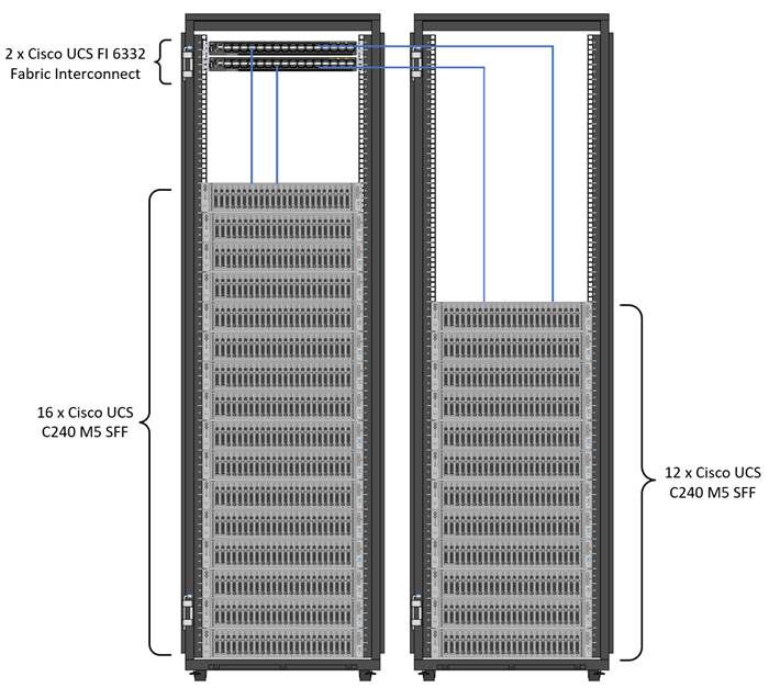
![]() Figure 1 with Cisco UCS C240 M5, can also be deployed with a fourth generation Cisco UCS 6454 Fabric Interconnect with 25G VIC. However, this could lead to performance slowdown, compared to a 40G VIC and FI.
Figure 1 with Cisco UCS C240 M5, can also be deployed with a fourth generation Cisco UCS 6454 Fabric Interconnect with 25G VIC. However, this could lead to performance slowdown, compared to a 40G VIC and FI.
As illustrated in Figure 1, a 28-node starter cluster. Rack #1 has 16 Cisco UCS C240 M5 servers. Each link in the figure represents a 40 Gigabit Ethernet link from each of the 16 servers directly connected to a Fabric Interconnect. Rack #2 has 12 Cisco UCS C240 M5 servers. Every server is connected to both Fabric Interconnects.
Figure 1 28 Node Starter Cluster Configuration for MAPR with K8s Managed Volume Drivers
Scaling the Solution
Figure 2 illustrates how to scale the solution. Each pair of Cisco UCS 6332 Fabric Interconnects has 28 Cisco UCS C240 M5 servers connected to it. This allows for four uplinks from each Fabric Interconnect to the Cisco Nexus 9332 switch. Six pairs of 6332 FI’s can connect to a single switch with four uplink ports each. With 28 servers per FI, a total of 168 servers can be supported. Additionally, we can scale to thousands of nodes with the Nexus 9500 series family of switches.
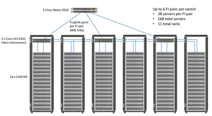
![]() 2 x Cisco UCS 6454 Fabric Interconnects can also be used in this reference design. For more information about Cisco UCS 6454 FI, go to https://www.cisco.com/c/en/us/products/collateral/servers-unified-computing/datasheet-c78-741116.html. Cisco UCS 6332 series FI supports 40 Gb end-to-end and is a good choice for higher bandwidth and faster connections. Cisco UCS 6454 can be considered, if you prefer to use 10/25Gb connections and get faster 40/100 Gb uplinks or move to 25Gb in the future.
2 x Cisco UCS 6454 Fabric Interconnects can also be used in this reference design. For more information about Cisco UCS 6454 FI, go to https://www.cisco.com/c/en/us/products/collateral/servers-unified-computing/datasheet-c78-741116.html. Cisco UCS 6332 series FI supports 40 Gb end-to-end and is a good choice for higher bandwidth and faster connections. Cisco UCS 6454 can be considered, if you prefer to use 10/25Gb connections and get faster 40/100 Gb uplinks or move to 25Gb in the future.
Cisco UCS Integrated Infrastructure for Big Data and Analytics
The Cisco UCS Integrated Infrastructure for Big Data and Analytics solution for MapR Data Platform is based on Cisco UCS Integrated Infrastructure for Big Data and Analytics, a highly scalable architecture designed to meet a variety of scale-out application demands with seamless data integration and management integration capabilities built using the components described in this section.
Cisco UCS Manager
Cisco UCS Manager (UCSM) resides within the Cisco UCS Fabric Interconnect. It makes the system self-aware and self-integrating, managing all of the system components as a single logical entity. Cisco UCS Manager can be accessed through an intuitive GUI, a CLI, or an XML API. Cisco UCS Manager uses service profiles to define the personality, configuration, and connectivity of all resources within Cisco UCS, radically simplifying provisioning of resources so that the process takes minutes instead of days. This simplification allows IT departments to shift their focus from constant maintenance to strategic business initiatives.
Key Features
· Supports Cisco UCS B-Series Blade and C-Series Rack Servers, the Cisco UCS C3260 storage server, Cisco UCS Mini, and the Cisco HyperFlex hyperconverged infrastructure.
· Programmatically controls server, network, and storage resources, with a unified, policy-driven management, so they can be efficiently managed at scale through software.
· Works with HTML 5, Java, or CLI graphical user interfaces.
· Can automatically detect, inventory, manage, and provision system components that are added or changed.
· Facilitates integration with third-party systems management tools.
· Builds on existing skills and supports collaboration across disciplines through role-based administration.
Cisco UCS 6300 Series Fabric Interconnects
Cisco UCS 6300 Series Fabric Interconnects provide high-bandwidth, low-latency connectivity for servers, with integrated, unified management provided for all connected devices by Cisco UCS Manager. Deployed in redundant pairs, Cisco fabric interconnects offer the full active-active redundancy, performance, and exceptional scalability needed to support the large number of nodes that are typical in clusters serving big data applications. Cisco UCS Manager enables rapid and consistent server configuration using service profiles, automating ongoing system maintenance activities such as firmware updates across the entire cluster as a single operation. Cisco UCS Manager also offers advanced monitoring with options to raise alarms and send notifications about the health of the entire cluster.
The Cisco UCS 6300 series Fabric interconnects are a core part of Cisco UCS, providing low-latency, lossless 10 and 40 Gigabit Ethernet, Fiber Channel over Ethernet (FCoE), and Fiber Channel functions with management capabilities for the entire system. All servers attached to Fabric interconnects become part of a single, highly available management domain.
Figure 3 Cisco UCS 6332 UP 32 -Port Fabric Interconnect
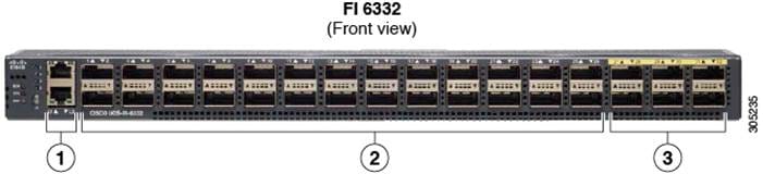
| 1 |
L1 and L2 high availability ports |
||
| 2 |
28 X 40G QSFP ports ( 98 X 10G SFP ports)
|
||
| 3 |
6 X 40G QSFP ports |
Cisco UCS C-Series Rack-Mount Servers
The Cisco UCS C240 M5 Rack-Mount Server (Figure 4) is a 2-socket, 2-Rack-Unit (2RU) rack server offering industry-leading performance and expandability. It supports a wide range of storage and I/O-intensive infrastructure workloads, from big data and analytics to collaboration. Cisco UCS C-Series Rack Servers can be deployed as standalone servers or as part of a Cisco UCS managed environment to take advantage of Cisco’s standards-based unified computing innovations that help reduce customers’ TCO and increase their business agility.
In response to ever-increasing computing and data-intensive real-time workloads, the enterprise-class Cisco UCS C240 M5 server extends the capabilities of the Cisco UCS portfolio in a 2RU form factor. It incorporates the Intel Xeon Scalable processors, supporting up to 20 percent more cores per socket, twice the memory capacity, and five times more
Non-Volatile Memory Express (NVMe) PCI Express (PCIe) Solid-State Disks (SSDs) compared to the previous generation of servers. These improvements deliver significant performance and efficiency gains that will improve your application performance. The Cisco UCS C240 M5 delivers outstanding levels of storage expandability with exceptional performance, along with the following:
· Latest Intel Xeon Scalable CPUs with up to 28 cores per socket
· Up to 24 DDR4 DIMMs for improved performance
· Up to 26 hot-swappable Small-Form-Factor (SFF) 2.5-inch drives, including 2 rear hot-swappable SFF drives (up to 10 support NVMe PCIe SSDs on the NVMe-optimized chassis version), or 12 Large-Form- Factor (LFF) 3.5-inch drives plus 2 rear hot-swappable SFF drives
· Support for 12-Gbps SAS modular RAID controller in a dedicated slot, leaving the remaining PCIe Generation 3.0 slots available for other expansion cards
· Modular LAN-On-Motherboard (mLOM) slot that can be used to install a Cisco UCS Virtual Interface Card (VIC) without consuming a PCIe slot, supporting dual 10- or 40-Gbps network connectivity
· Dual embedded Intel x550 10GBASE-T LAN-On-Motherboard (LOM) ports
· Modular M.2 or Secure Digital (SD) cards that can be used for boot
Figure 4 Cisco UCS C240 M5 Rack-Mount Server

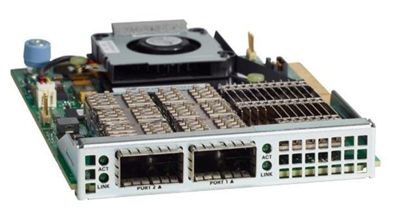
Cisco UCS Virtual Interface Cards
Cisco UCS Virtual Interface Cards (VICs) are unique to Cisco. Cisco UCS Virtual Interface Cards incorporate next-generation converged network adapter (CNA) technology from Cisco and offer dual 10- and 40-Gbps ports designed for use with Cisco UCS servers. Optimized for virtualized networking, these cards deliver high performance and bandwidth utilization, and support up to 256 virtual devices.
The Cisco UCS Virtual Interface Card 1387 offers dual-port Enhanced Quad Small Form-Factor Pluggable (QSFP+) 40 Gigabit Ethernet and Fiber Channel over Ethernet (FCoE) in a modular-LAN-on-motherboard (mLOM) form factor. The mLOM slot can be used to install a Cisco VIC without consuming a PCIe slot providing greater I/O expandability.
Figure 5 Cisco UCS VIC 1387
Cisco Intersight Cloud Based Management
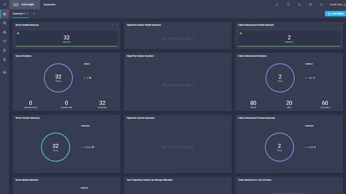
Cisco Intersight is Cisco’s new systems management platform that delivers intuitive computing through cloud-powered intelligence. This platform offers a more intelligent level of management that enables IT organizations to analyze, simplify, and automate their environments in ways that were not possible with prior generations of tools. This capability empowers organizations to achieve significant savings in Total Cost of Ownership (TCO) and to deliver applications faster, so they can support new business initiates. The advantages of the model-based management of the Cisco UCS platform plus Cisco Intersight are extended to Cisco UCS servers and Cisco HyperFlex and Cisco HyperFlex Edge systems. Cisco HyperFlex Edge is optimized for remote sites, branch offices, and edge environments.
The Cisco UCS and Cisco HyperFlex platforms use model-based management to provision servers and the associated storage and fabric automatically, regardless of form factor. Cisco Intersight works in conjunction with Cisco UCS Manager and the Cisco® Integrated Management Controller (IMC). By simply associating a model-based configuration with a resource through service profiles, your IT staff can consistently align policy, server personality, and workloads. These policies can be created once and used by IT staff with minimal effort to deploy servers. The result is improved productivity and compliance and lower risk of failures due to inconsistent configuration.
Cisco Intersight will be integrated with data center, hybrid cloud platforms and services to securely deploy and manage infrastructure resources across data center and edge environments. In addition, Cisco will provide future integrations to third-party operations tools to allow customers to use their existing solutions more effectively.
Figure 6 Cisco Intersight Dashboard Example
MapR Data Platform
The MapR Data Platform provides enterprise-class big data solutions that are fast to develop and easy to administer. With significant investment in critical technologies, MapR offers one of the industry’s most comprehensive data platforms, fully optimized for performance and scalability. MapR’s distribution delivers more than a dozen tested and validated Hadoop software modules over a fortified data platform, offering exceptional ease of use, reliability and performance for big data solutions.
The features of MapR Data Platform are as follows:
· Performance – Fast performance and throughput with low latency
· Scalability – Up to a trillion files, with no restrictions on the number of nodes in a cluster
· Standards-based API’s and tools – Standard Hadoop API’s, ODBC, JDBC, LDAP, Linux PAM, and more
· MapR Direct Access NFS – Random read/write, real-time data flows, existing non-Java applications work seamlessly
· Manageability – Advanced management console, rolling upgrades, REST API support
· Integrated security – Kerberos and non-Kerberos options with wire-level encryption
· Advanced multi-tenancy – Volumes, data placement control, job placement control, queues, and more
· Consistent snapshots – Full data protection with point-in-time recovery
· High availability – Ubiquitous HA with a no-NameNode architecture, YARN HA, NFS HA
· Disaster recovery – Cross-site replication with mirroring
· MapR-DB – Integrated enterprise-grade NoSQL database
· MapR Streams – Global publish-subscribe event streaming system for big data
MapR Data Platform is a hardened big data platform designed for the demanding requirements of enterprise customers. MapR is the leading contributor to the Hadoop ecosystem, and has created a rich suite of complementary open source projects that are included in the MapR Data Platform.
All the integration and the entire solution is thoroughly tested and fully documented. By taking the guesswork out of building out a big data deployment, MapR gives a streamlined path to success in solving real business problems.
MapR Data Platform is:
· Unified – one integrated system, bringing diverse users and application workloads to one pool of data on common infrastructure; no data movement required
· Secure – perimeter security, authentication, granular authorization, and data protection
· Governed – enterprise-grade data auditing, data lineage, and data discovery
· Managed – native high-availability, fault-tolerance and self-healing storage, automated backup and disaster recovery, and advanced system and data management
· Open – Apache-licensed open source to ensure both data and applications remain copy righted, and an open platform to connect with all of the existing investments in technology and skills.
Figure 7 MapR Data Platform
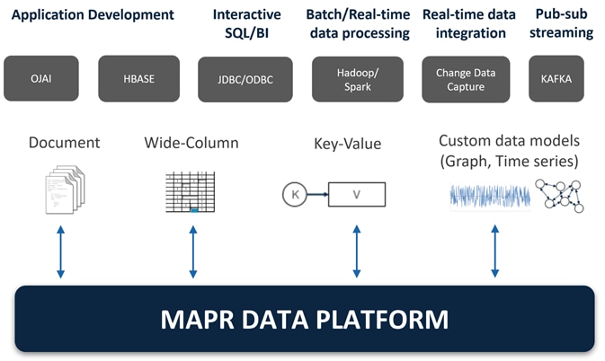
MapR provides a scalable, flexible, integrated platform that makes it easy to manage rapidly increasing volumes and varieties of data in any enterprise. Industry-leading MapR products and solutions enable customers to deploy and manage vast amount of data, manipulate and analyze that data, and keep that data secure and protected.
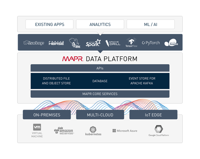
MapR Enterprise-Grade Platform Services
MapR Platform Services (Figure 8) are the core data handling capabilities of the MapR Data Platform. Modules include MapR-FS, MapR-Database and MapR Event Store for Apache Kafka. Its enterprise-friendly design provides a familiar set of file and data management services, including a global namespace, high availability, data protection, self-healing clusters, access control, real-time performance, secure multi-tenancy, and management and monitoring.
Figure 8 MapR Enterprise-Grade Platform Services
Enterprise Storage
MapR-FS is an enterprise standard POSIX file system that provides high-performance read/write data storage for the MapR Data Platform. MapR-FS includes important features for production deployments such as fast NFS access, access controls, and transparent data compression at a virtually unlimited scale.
Database
MapR-Database is an enterprise-grade, high performance, NoSQL database management system. It is used to add real-time, operational analytics capabilities to applications built on the Hadoop or Spark ecosystems. Because it is integrated into the MapR Data Platform, it inherits the protections and high-performance capabilities.
Event Streaming
MapR Event Store for Apache Kafka is a global publish-subscribe event streaming system for big data. It connects data producers and consumers worldwide in real-time, with unlimited scale. MapR Event Store is the first big data-scale streaming system built into a data platform. It makes data available instantly to stream processing and other applications and is the only big data streaming system to support global event replication reliably at IoT scale.
MapR Event Store: Event Streaming on a Global Scale
Many big data sources are continuous flows of data in real time: sensor data, log files, transaction data to name just a few. Enterprises are struggling to deal with the high volume and high velocity of the data using existing bulk data-oriented tools.
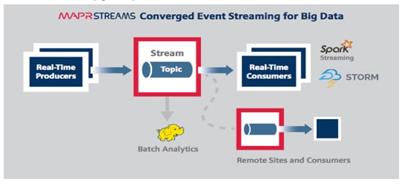
MapR Event Store (Figure 9) manages streaming data for real-time processing with enterprise-grade security and reliability at a global scale. It connects data producers and consumers worldwide in real time, with unlimited scale. MapR Event Store scales to billions of events per second, millions of topics, and millions of producer and consumer applications. Geographically dispersed MapR clusters can be joined into a global fabric, passing event messages between producer and consumer applications in any topology, including one-to-one and many-to-many.
This centralized architecture provides real-time access to streaming data for batch or interactive processing on a global scale with enterprise features including secure access-control, encryption, cross data center replication, multi-tenancy and utility-grade uptime.
Figure 9 MapR Event Store: Event Streaming for Big Data
MapR Event Store makes data available instantly to stream processing and other applications, providing:
· Kafka API for real-time producers and consumers for easy application migration.
· Out-of-the-box integration with popular stream processing frameworks like Spark Streaming and Flink.
MapR Event Store globally replicates event data at IoT-scale with:
· Arbitrary topology supporting thousands of clusters across the globe. Topologies of connected clusters include one-to-one, one-to-many, many-to-one, many-to-many, star, ring, and mesh. Topology loops are automatically handled to avoid data duplication.
· Global metadata replication. Stream metadata is replicated alongside data, allowing producers and consumers to failover between sites for high availability. Data is spread across geographically distributed locations via cross-cluster replication to ensure business continuity should an entire site-wide disaster occur.
MapR Open Source Technologies
MapR packages a broad set of Apache open source ecosystem projects that enable big data applications. The goal is to provide an open platform that provides the right tool for the job. MapR tests and integrates open source ecosystem projects such as Spark, Drill, HBase, among others. MapR is the only big data vendor that supports multiple versions of key Apache projects providing more flexibility in updating the environment.
Figure 10 MapR Open Source Engines and Tool
Figure 10 shows the Apache open source projects supported by the MapR Data Platform. Features of some of the key technologies are highlighted below. In conjunction with the data ingestion capabilities provided by MapR Event Store these technologies are building blocks for a system based on the Lambda Architecture.
MapReduce
MapReduce is a powerful framework for processing large, distributed sets of structured or unstructured data on a Hadoop cluster. The key feature of MapReduce is its ability to perform processing across an entire cluster of nodes, with each node processing its local data. This feature makes MapReduce orders of magnitude faster than legacy methods of processing big data. MapReduce is a common choice to perform the pre-compute processing of batch views in the batch layer of the Lambda Architecture.
HBase
HBase is a database that runs on a Hadoop cluster. It is not a traditional relational database management system (RDBMS). Data stored in HBase also does not need to fit into a rigid schema as with an RDBMS, making it ideal for storing unstructured or semi-structured data. HBase stores data in a table-like format with the ability to store billions of rows with millions of columns over multiple nodes in a cluster. HBase can be used to store the pre-computed batch views of data held in the serving layer of the Lambda Architecture.
Drill
Drill is an open source, low-latency query engine for big data that delivers secure and interactive SQL analytics at petabyte scale. It can discover schemas on-the-fly and enable immediate exploration of data stored in Hadoop and NoSQL stores across a variety of data formats and sources.
Drill is fully ANSI SQL compliant, integrates seamlessly with existing BI and visualization tools, and supports thousands of users across thousands of nodes accessing data in the terabyte and petabyte range. Drill can operate on the merged view of data from the serving layer and speed layer of the Lambda Architecture providing a complete historical and real-time picture.
Spark
Spark is a fast and general-purpose engine for large-scale data processing. By adding Spark to the Hadoop deployment and analysis platform and running it all on Cisco UCS Integrated Infrastructure for Big Data and Analytics, customers can accelerate streaming, interactive queries, machine learning and batch workloads, and offering experiences that deliver more insights in less time.
Spark unifies a broad range of capabilities: batch processing, real-time stream processing, advanced analytic capabilities, machine learning and interactive exploration that can intelligently optimize applications. Spark’s key advantage is speed: most operations are performed in memory eliminating disk I/O as a constraint; calculations are performed, and results are delivered only when needed; and results can be configured to persist in memory making multiple reads of the same dataset orders of magnitude faster than traditional MapReduce programs.
In the Lambda Architecture, Spark can replace the MapReduce calculation of pre-computed batch views in the batch layer. It can also be used for fast, interactive analysis on the merged view of data from the serving and speed layers. Finally, Spark Streaming operates on data in real-time in the speed layer.
Spark Streaming
Spark Streaming is an extension of the core Spark API that enables high-throughput, fault-tolerant stream processing of live data streams. Data can be ingested from many sources like MapR Streams, Kafka, Flume, Twitter or TCP sockets and processed using complex algorithms expressed with high-level distributed data processing functions like map, reduce and join.
Processed data can be pushed out to file systems, databases and live dashboards. Spark Streaming is built on top of Spark, so users can apply Spark's built-in machine learning algorithms (MLlib) and graph processing algorithms (GraphX) on data streams.
Spark Streaming brings Spark's language-integrated API to stream processing, letting users write streaming applications the same way as batch jobs (in Java, Python and Scala). It is also highly fault-tolerant, able to detect and recover from data loss mid-stream due to node or process failure.
The MapR Data Platform enables the development of streaming and NoSQL applications on a single cluster. By using Spark Streaming, MapR Streams, and MapR-DB together, real-time operational applications can be developed that allow for data ingestion at high speeds.
Requirements
This CVD describes architecture and deployment procedures for MapR Data Platform on a 28-node cluster based on Cisco UCS Integrated Infrastructure for Big Data and Analytics. The solution goes into detail configuration of MapR 6.1.0 on the Cisco UCS infrastructure and all of its dependencies.
The cluster configuration consists of the following:
· Two Cisco UCS 6332UP Fabric Interconnects
· 28 UCS C240 M5 Rack-Mount servers
· Two Cisco R42610 standard racks
· Four Vertical Power distribution units (PDUs) (Country Specific)
Physical Topology
Each rack consists of two vertical PDUs. The first rack consists of two Cisco UCS 6332UP Fabric Interconnects, 16 Cisco UCS C240 M5 Rack Servers connected to each of the vertical PDUs for redundancy; thereby, ensuring availability during power source failure. The second rack consists of 12 Cisco UCS C240 M5 Servers connected to each of the vertical PDUs for redundancy; thereby, ensuring availability during power source failure, similar to the first rack.
![]() Please contact your Cisco representative for country specific information.
Please contact your Cisco representative for country specific information.
Table 2 lists the rack configurations.
| Cisco |
First Rack |
Cisco |
Second Rack |
| 42URack |
|
42URack |
|
| 42 |
Cisco UCS FI 6332UP |
42 |
Unused |
| 41 |
Cisco UCS FI 6332UP |
41 |
Unused |
| 40 |
Unused Unused |
40 |
Unused |
| 39 |
39 |
Unused |
|
| 38 |
Unused |
38 |
Unused |
| 37 |
Unused |
37 |
Unused |
| 36 |
Unused Unused |
36 |
Unused |
| 35 |
35 |
Unused |
|
| 34 |
Unused Unused |
34 |
Unused |
| 33 |
33 |
Unused |
|
| 32 |
Cisco UCS C240 M5 |
32 |
Unused |
| 31 |
31 |
Unused |
|
| 30 |
Cisco UCS C240 M5 |
30 |
Unused |
| 29 |
29 |
Unused |
|
| 28 |
Cisco UCS C240 M5 |
28 |
Unused |
| 27 |
27 |
Unused |
|
| 26 |
Cisco UCS C240 M5 |
26 |
Unused |
| 25 |
25 |
Unused |
|
| 24 |
Cisco UCS C240 M5 |
24 |
Cisco UCS C240 M5 |
| 23 |
23 |
||
| 22 |
Cisco UCS C240 M5 |
22 |
Cisco UCS C240 M5 |
| 21 |
21 |
||
| 20 |
Cisco UCS C240 M5 |
20 |
Cisco UCS C240 M5 |
| 19 |
19 |
||
| 18 |
Cisco UCS C240 M5 |
18 |
Cisco UCS C240 M5 |
| 17 |
17 |
||
| 16 |
Cisco UCS C240 M5 |
16 |
Cisco UCS C240 M5 |
| 15 |
15 |
||
| 14 |
Cisco UCS C240 M5 |
14 |
Cisco UCS C240 M5 |
| 13 |
13 |
||
| 12 |
Cisco UCS C240 M5 |
12 |
Cisco UCS C240 M5 |
| 11 |
11 |
||
| 10 |
Cisco UCS C240 M5 |
10 |
Cisco UCS C240 M5 |
| 9 |
9 |
||
| 8 |
Cisco UCS C240 M5 |
8 |
Cisco UCS C240 M5 |
| 7 |
7 |
||
| 6 |
Cisco UCS C240 M5 |
6 |
Cisco UCS C240 M5 |
| 5 |
5 |
||
| 4 |
Cisco UCS C240 M5 |
4 |
Cisco UCS C240 M5 |
| 3 |
3 |
||
| 2 |
Cisco UCS C240 M5 |
2 |
Cisco UCS C240 M5 |
| 1 |
1 |
Port Configuration on Fabric Interconnect
Table 3 lists port configuration on Cisco UCS FI 6332 Fabric Interconnect.
Table 3 Port Configuration on Fabric Interconnect
| Port Type |
Port Number |
| Server |
1-28 |
| Network |
29-32 |
Server Configuration and Cabling for Cisco UCS C240 M5
The Cisco UCS C240 M5 rack server is equipped with 2 x Intel Xeon Scalable Family Processor 6132 (2 x 14 cores, 2.6 GHz), 192 GB of memory, Cisco UCS Virtual Interface Card 1337, Cisco 12-Gbps SAS Modular Raid Controller with 4-GB FBWC, 26 x 1.8 TB 10K rpm SFF SAS HDDs or 12 x 1.6 TB Enterprise Value SATA SSDs, M.2 with 2 x 240-GB SSDs for Boot.
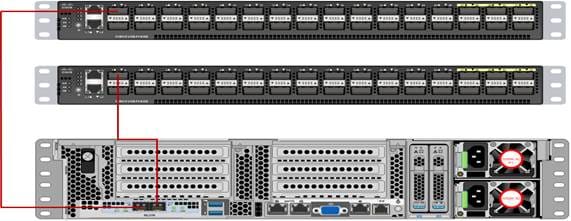
Figure 11 illustrates the port connectivity between the Cisco UCS FI 6332 and Cisco UCS C240 M5 Rack Server. 28 Cisco UCS C240 M5 servers are used in the master rack configuration.
Figure 11 Fabric Topology for Cisco UCS C240 M5
For information about physical connectivity, single-wire management, and cluster setup go to:
Software Distributions and Versions
The software distributions required versions are listed below.
· MapR (MapR 6.1.0)
The MapR Data Platform used is 6.1.0. For more information visit: https://www.mapr.com
· SUSE Linux Enterprise Server (SLES 12-SP3)
The operating system supported is SUSE Linux Enterprise Server 12 SP3. For more information go to: https://www.suse.com
Software Versions
The software versions tested and validated in this document are listed in Table 4.
| Layer |
Component |
Version or Release |
| Compute |
Cisco UCS C240-M5 |
C240M5.4.0.1h.0 |
| Network |
Cisco UCS 6332 |
UCS 4.0.(1d)A |
| Cisco UCS VIC1387 Firmware |
4.3(1b) |
|
| Cisco UCS VIC1387 Driver |
3.0.107.37-492.52 |
|
| Storage |
SAS Expander |
65.02.15.00 |
|
|
Cisco 12G Modular Raid controller |
50.1.0-1456 |
|
|
LSI MegaRAID SAS Driver |
07.703.06.00 |
| Software |
SUSE Linux Enterprise Server |
12 SP3 |
| Cisco UCS Manager |
4.0(1d) |
|
| MAPR |
6.1.0 |
![]() The latest driver can be downloaded here: https://software.cisco.com/download/home/283862063/type/283853158/release/3.1%25283%2529.
The latest driver can be downloaded here: https://software.cisco.com/download/home/283862063/type/283853158/release/3.1%25283%2529.
![]() The Latest Supported RAID controller Driver is already included with the SLES 12-SP3 operating system.
The Latest Supported RAID controller Driver is already included with the SLES 12-SP3 operating system.
![]() Cisco UCS C240 M5 Rack Servers with Intel Scalable Family Processors are supported from Cisco UCS Manager version 3.2 onwards.
Cisco UCS C240 M5 Rack Servers with Intel Scalable Family Processors are supported from Cisco UCS Manager version 3.2 onwards.
Cisco Unified Computing System Configuration
This section details the Cisco UCS configuration that was done as part of the infrastructure build out. The racking, power, and installation of the Cisco UCS Rack Server is described in the physical topology section earlier in this document. Please refer to the Cisco UCS Manager Getting Started Guide. For more information about each step, refer to the following document, Cisco UCS Manager - Configuration Guides.
Configure Cisco UCS Fabric Interconnect
This document assumes you are using Cisco UCS Manager Software version 4.0(1d). To upgrade the Cisco UCS Manager software and the Cisco UCS 6332-16UP Fabric Interconnect software to a newer version of the firmware, see Cisco UCS Manager Install and Upgrade Guides.
To configure Cisco UCS Fabric Interconnect, follow these steps:
1. Connect a console cable to the console port on what will become the primary fabric interconnect.
2. If the fabric interconnects were previously deployed and you want to erase it to redeploy, log in with the existing user name and password.
#connect local-mgmt
#erase config
#yes (to confirm)
3. After the fabric interconnect restarts, the out-of-box first time installation prompt appears, type “console” and press Enter.
4. Follow the Initial Configuration steps as outlined in Cisco UCS Manager Getting Started Guide. When configured, log into UCSM IP Address via Web interface to perform base Cisco UCS configuration.
Configure Fabric Interconnects for a Cluster Setup
To configure the Cisco UCS Fabric Interconnects, follow these steps:
1. Verify the following physical connections on the fabric interconnect:
a. The management Ethernet port (mgmt0) is connected to an external hub, switch, or router.
b. The L1 ports on both fabric interconnects are directly connected to each other.
c. The L2 ports on both fabric interconnects are directly connected to each other
d. Connect to the console port on the first Fabric Interconnect.
e. Review the settings on the console. Answer yes to Apply and Save the configuration.
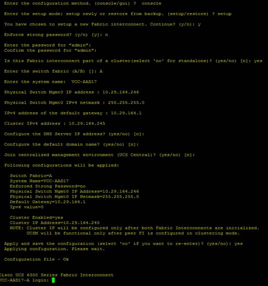
f. Wait for the login prompt to make sure the configuration has been saved to Fabric Interconnect A.
Figure 12 Initial Setup of Cisco UCS Manager on Primary Fabric Interconnect
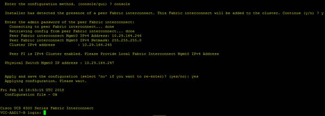
2. Connect the console port on the second Fabric Interconnect, configure secondary FI.
Figure 13 Initial Setup of Cisco UCS Manager on Secondary Fabric Interconnect
3. To log into the Cisco Unified Computing System (Cisco UCS) environment, follow these steps:
a. Open a web browser and navigate to the Cisco UCS Fabric Interconnect cluster address configured above.
b. Click the Launch UCS Manager link to download the Cisco UCS Manager software. If prompted, accept the security certificates.
Configure Base Cisco Unified Computing System
The following are the high-level steps involved for a Cisco UCS configuration:
1. Configure Fabric Interconnects for a Cluster Setup.
2. Set Fabric Interconnects to Fibre Channel End Host Mode.
3. Synchronize Cisco UCS to NTP.
4. Configure Fabric Interconnects for Rack or Chassis and Blade Server Discovery.
5. Configure Global Policies.
6. Configure Server Ports.
7. Configure LAN on Cisco UCS Manager.
8. Configure Ethernet LAN Uplink Ports.
9. Set QoS system class and Jumbo Frames in both the Cisco Fabric Interconnect.
10. Create Uplink Port Channels to Cisco Nexus Switches.
11. Configure FC SAN Uplink Ports
12. Configure VLAN.
13. Configure IP, UUID, Server, MAC Pool and policy.
14. IP Pool Creation.
15. UUID Suffix Pool Creation.
16. Server Pool Creation.
17. Configure Server BIOS Policy.
18. Create Adapter Policy.
19. Configure Default Maintenance Policy.
20. Configure vNIC Template.
21. Create Server Boot Policy.
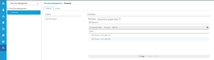
Synchronize Cisco UCS Manager to NTP
To synchronize the Cisco UCS environment to the NTP server, follow these steps:
1. In Cisco UCS Manager, in the navigation pane, click the Admin tab.
2. Select All > Time zone Management.
3. In the Properties pane, select the appropriate time zone in the Time zone menu.
4. Click Save Changes and then click OK.
5. Click Add NTP Server.
6. Enter the NTP server IP address and click OK.
7. Click OK to finish.
8. Click Save Changes.
Figure 14 Synchronize Cisco UCS Manager to NTP
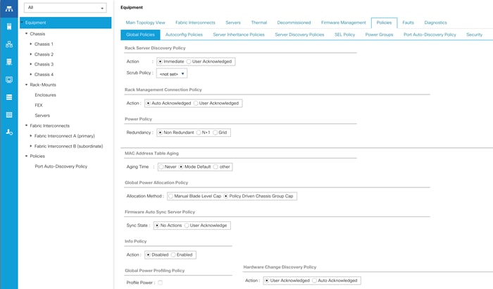
Configure Global Policies
The rack server and chassis discovery policy determines how the system reacts when you add a new rack server or chassis. We recommend using the platform max value as shown. Using platform max helps ensure that Cisco UCS Manager uses the maximum number of IOM uplinks available.
To configure the Global Policies, follow this step:
1. In Cisco UCS Manager; Go to Equipment > Policies (right pane) > Global Policies as shown in Figure 15.
Figure 15 Global Policies in Cisco UCS Manager
Configure Server Ports
You configure server ports to initiate chassis and blade discovery. To configure server ports, follow these steps:
1. Go to Equipment > Fabric Interconnects > Fabric Interconnect A > Fixed Module > Ethernet Ports.
2. Select the ports (for this solution ports are 1-28) which are connected to the Cisco UCS VIC 1387 on Cisco UCS C240 M5 rack server.
3. Right-click and select Configure as Server Port.
Figure 16 Configure Server Port on Cisco UCS Manager Fabric Interconnect for Server/Chassis Discovery
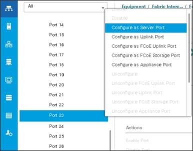
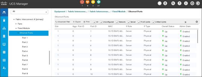
Figure 17 Ports Status after the Server Discover
Configure Uplink Ports
You configure network ports to connect to the datacenter network switch.
![]() In our solution study we connected to Nexus 9000 series switch.
In our solution study we connected to Nexus 9000 series switch.
To configure Network ports, follow these steps:
1. Go to Equipment > Fabric Interconnects > Fabric Interconnect A > Fixed Module > Ethernet Ports.
2. Select the ports (for this solution ports are 29-32) which are connected to the Cisco Nexus 9000 series switch for northbound network connectivity.
3. Right-click and select Configure as Network Port.
Figure 18 Configure Network Port on Cisco UCS Manager Fabric Interconnect
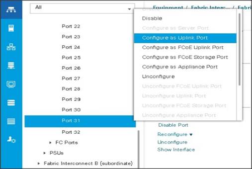
![]() After the Server port and network port configuration on Cisco UCS FI 6332 Port 1-28 are utilized for server management and data traffic and 29-32 will be a Network Port.
After the Server port and network port configuration on Cisco UCS FI 6332 Port 1-28 are utilized for server management and data traffic and 29-32 will be a Network Port.
Create New Organization
To configure the necessary Organization for the Cisco UCS environment, follow these steps:
1. In Cisco UCS Manager, click the Servers tab in the navigation pane.
2. Select root > Sub-Organization.
3. Right-click Sub-Organization.
4. Enter the name of the Organization.
5. Click OK.
Figure 19 Create a New Organization
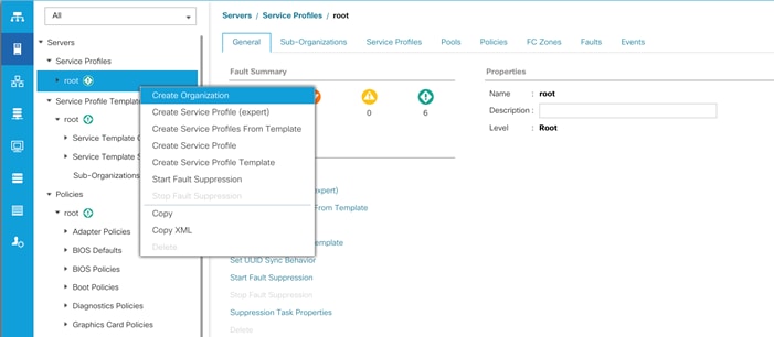
Figure 20 Assign Name for New Organization
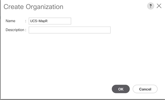
You will create pools and policies required for this solution under the newly created “UCS-MapR” Organization.
Configure IP, UUID, Server, and MAC Pools
IP Pool Creation
An IP address pool on the out of band management network must be created to facilitate KVM access to each compute node in the Cisco UCS domain.
To create a block of IP addresses for server KVM access in the Cisco UCS environment, follow these steps:
1. In Cisco UCS Manager, in the navigation pane, click the LAN tab.
2. Select Pools > root > Sub-Organizations > UCS-MapR > IP Pools > click Create IP Pool.
3. Select option Sequential to assign IP in sequential order then click Next.
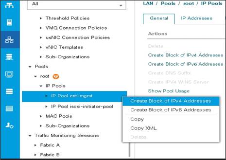
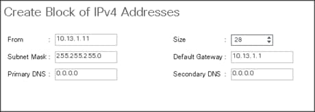
4. Click Add IPv4 Block.
5. Enter the starting IP address of the block and the number of IP addresses required, and the subnet and gateway information as shown below.
UUID Suffix Pool Creation
To configure the necessary universally unique identifier (UUID) suffix pool for the Cisco UCS environment, follow these steps:
1. In Cisco UCS Manager, click the Servers tab in the navigation pane.
2. Select Pools > root > Sub-Organization > UCS-MapR.
3. Right-click UUID Suffix Pools and then select Create UUID Suffix Pool.
4. Enter the name of the UUID name.
5. Optional: Enter a description for the UUID pool.
6. Keep the prefix at the derived option and select Sequential in as Assignment Order then click Next.
Figure 21 UUID Suffix Pool Creation
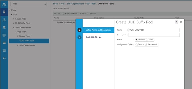
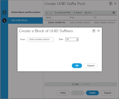
Figure 22 Create a Block of UUID Suffixes
Server Pool Creation
To configure the necessary server pool for the Cisco UCS environment, follow these steps:
![]() Consider creating unique server pools to achieve the granularity that is required in your environment.
Consider creating unique server pools to achieve the granularity that is required in your environment.
1. In Cisco UCS Manager, click the Servers tab in the navigation pane.
2. Select Pools > root > Sub-Organization > UCS-MapR> right-click Server Pools > Select Create Server Pool.
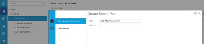
3. Enter name of the server pool.
4. Optional: Enter a description for the server pool then click Next.
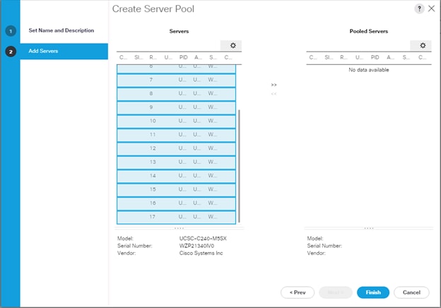
Figure 23 Create a Server Pool
5. Select servers to be used for the deployment and click > to add them to the server pool. In our case we added thirty servers in this server pool.
6. Click Finish and then click OK.
Figure 24 Add a Server in the Server Pool
MAC Pool Creation
To configure the necessary MAC address pools for the Cisco UCS environment, follow these steps:
1. In Cisco UCS Manager, click the LAN tab in the navigation pane.
2. Select Pools > root > Sub-Organization > UCS-MapR > right-click MAC Pools under the root organization.
3. Select Create MAC Pool to create the MAC address pool.
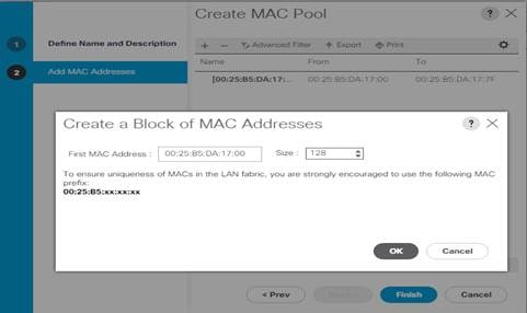
4. Enter a name for MAC pool. Select the Assignment Order as Sequential.
5. Enter the seed MAC address and provide the number of MAC addresses to be provisioned.
6. Click OK and then click Finish.
7. In the confirmation message, click OK.
Figure 25 Creating a Block of MAC Address
Configure VLAN
To configure the necessary virtual local area networks (VLANs) for the Cisco UCS environment, follow these steps:
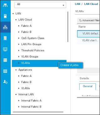
1. In Cisco UCS Manager, click the LAN tab in the navigation pane.
2. Select LAN > LAN Cloud.
3. Right-click VLANs
4. Select Create VLANs.
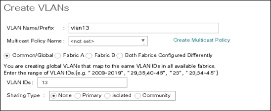
5. Enter Public_Traffic for the name of the VLAN to be used for Public Network Traffic.
6. Keep the Common/Global option selected for the scope of the VLAN.
7. Enter 13 for the ID of the VLAN ID.
8. Keep the Sharing Type as None.
Figure 26 Create VLANs
![]() The NIC carries the data traffic from VLAN13. A single vNIC is used in this configuration and the Fabric Failover feature in Fabric Interconnects handles any physical port down issues. It’s a seamless transition from an application perspective.
The NIC carries the data traffic from VLAN13. A single vNIC is used in this configuration and the Fabric Failover feature in Fabric Interconnects handles any physical port down issues. It’s a seamless transition from an application perspective.
Figure 27 Create VLANs
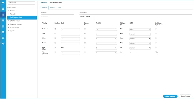
Set System class QoS and Jumbo Frame in Both the Cisco Fabric Interconnect
To configure jumbo frames and enable quality of service in the Cisco UCS fabric, follow these steps:
1. In Cisco UCS Manager, click the LAN tab in the navigation pane.
2. Select LAN > LAN Cloud > QoS System Class.
3. In the right pane, click the General tab.
4. On the Best Effort row, enter 9216 in the box under the MTU column.
5. Click Save Changes.
6. Click OK.
![]() Changing QoS system class MTU requires reboot of Cisco UCS Fabric Interconnect for changes to be effective.
Changing QoS system class MTU requires reboot of Cisco UCS Fabric Interconnect for changes to be effective.
Figure 28 Configure System Class QoS on UCS Fabric Interconnects
Create QoS Policies
To create the QoS policy to assign priority based on the class using the Cisco UCS Manager GUI, follow these steps:
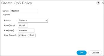
Platinum Policy
1. Select LAN tab in the left pane in the Cisco UCS Manager GUI.
2. Select LAN > Policies > root > UCS-MapR > QoS Policies.
3. Right-click QoS Policies.
4. Select Create QoS Policy.
Figure 29 Create a QoS Policy
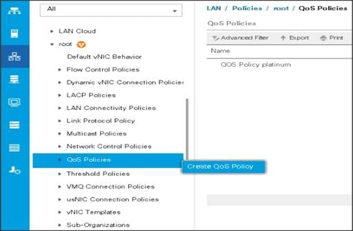
Figure 30 Create a Platinum QoS Policy
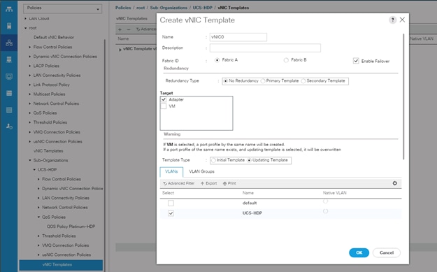
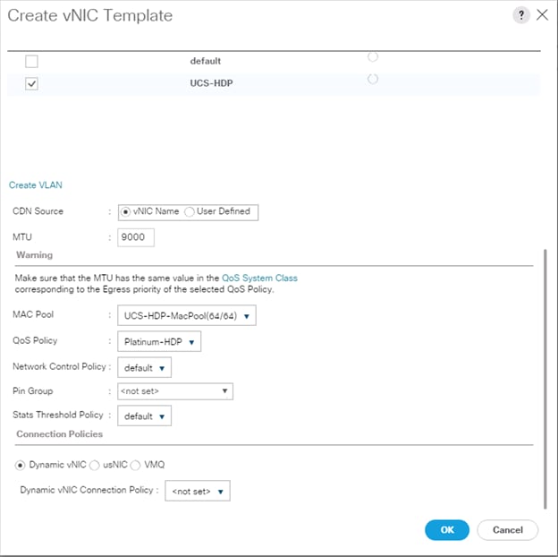
Create vNIC Templates
To create multiple virtual network interface card (vNIC) templates for the Cisco UCS environment, follow these steps:
1. In Cisco UCS Manager, click the LAN tab in the navigation pane.
2. Select Policies > root > Sub-Organization > UCS-MapR > vNIC Template.
3. Right-click vNIC Templates.
4. Select Create vNIC Template.
5. Enter name for vNIC template.
6. Keep Fabric A selected. Select the Enable Failover checkbox.
7. Select Updating Template as the Template Type.
8. Under VLANs, select the checkboxes for desired VLANs to add as part of the vNIC Template.
9. Set Native-VLAN as the native VLAN.
10. For MTU, enter 9000.
11. In the MAC Pool list, select MAC Pool configured.
12. Select Network Control Policy.
13. Click OK to create the vNIC template.
Figure 31 Create a vNIC Template
![]() If the solutions is being implemented with 6454 with 10G or 25G, MAPR_SUBNETS could be enabled pointing to two different subnets with additional vNICs. Instead of creating a single vNIC with traffic flowing through one fabric (A), we can enable MapR drive data traffic on both the fabrics by creating a second vNIC with traffic flowing on the other fabric B with a failover to fabric A.
If the solutions is being implemented with 6454 with 10G or 25G, MAPR_SUBNETS could be enabled pointing to two different subnets with additional vNICs. Instead of creating a single vNIC with traffic flowing through one fabric (A), we can enable MapR drive data traffic on both the fabrics by creating a second vNIC with traffic flowing on the other fabric B with a failover to fabric A.
![]() MapR Subnet and MapR External Advanced Options can be configured as outlined in the MapR administrator guide: https://mapr.com/docs/61/AdministratorGuide/DesignatingNICs.html
MapR Subnet and MapR External Advanced Options can be configured as outlined in the MapR administrator guide: https://mapr.com/docs/61/AdministratorGuide/DesignatingNICs.html
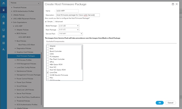
Create Host Firmware Package
Firmware management policies allow the administrator to select the corresponding packages for a given server configuration. These policies often include packages for adapter, BIOS, board controller, FC adapters, host bus adapter (HBA) option ROM, and storage controller properties.
To create a firmware management policy for a given server configuration in the Cisco UCS environment, follow these steps:
1. In Cisco UCS Manager, click the Servers tab in the navigation pane.
2. Select root > Sub-Organization > UCS-MapR > Host Firmware Packages.
3. Right-click Host Firmware Packages.
4. Select Create Host Firmware Package.
5. Enter name of the host firmware package.
6. Leave Simple selected.
7. Select the version.
8. Click OK to create the host firmware package.
Figure 32 Host Firmware Package Creation
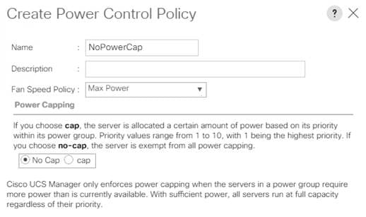
Create Power Control Policy
To create a power control policy for the Cisco UCS environment, follow these steps:
1. In Cisco UCS Manager, click the Servers tab in the navigation pane.
2. Select Policies > root > Sub-Organization > UCS-MapR > Power Control Policies.
3. Right-click Power Control Policies.
4. Select Create Power Control Policy.
5. Select Fan Speed Policy as Max Power.
6. Enter NoPowerCap as the power control policy name.
7. Change the power capping setting to No Cap.
8. Click OK to create the power control policy.
Figure 33 Create Power Control Policy
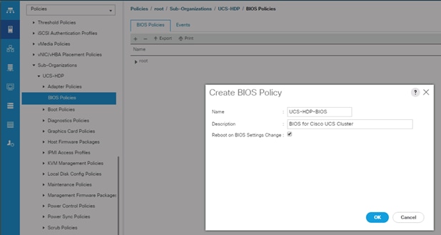
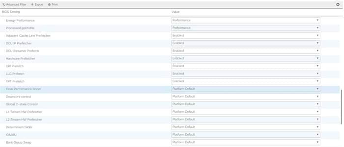
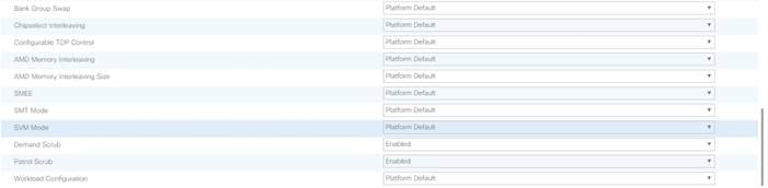
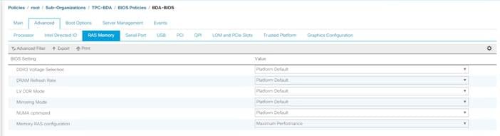
Create Server BIOS Policy
To create a server BIOS policy for the Cisco UCS environment, follow these steps:
1. In Cisco UCS Manager, click the Servers tab in the navigation pane.
2. Select Policies > root > Sub-Organization > UCS-HDP > BIOS Policies.
3. Right-click BIOS Policies.
4. Select Create BIOS Policy.
5. Enter C240M5-BIOS as the BIOS policy name.
Figure 34 BIOS Configuration
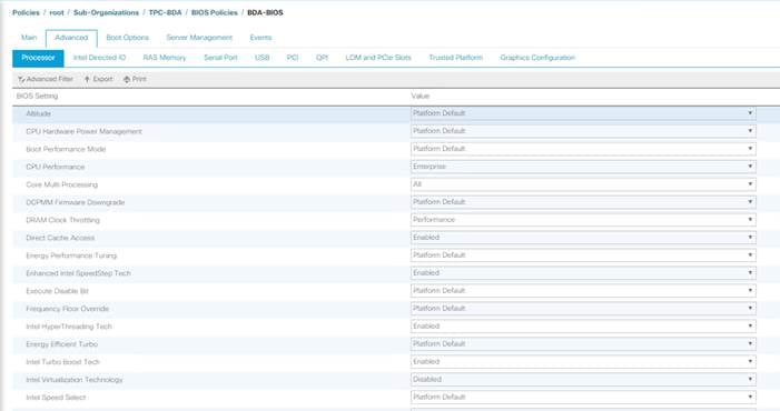

Cisco UCS M5 Server Performance Tuning guide: https://www.cisco.com/c/dam/en/us/products/collateral/servers-unified-computing/ucs-b-series-blade-servers/whitepaper_c11-740098.pdf
![]() BIOS settings can have a significant performance impact, depending on the workload and the applications. The BIOS settings listed in this section is for configurations optimized for best performance which can be adjusted based on the application, performance, and energy efficiency requirements.
BIOS settings can have a significant performance impact, depending on the workload and the applications. The BIOS settings listed in this section is for configurations optimized for best performance which can be adjusted based on the application, performance, and energy efficiency requirements.
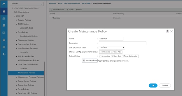
Configure Maintenance Policy
To update the default Maintenance Policy, follow these steps:
1. In Cisco UCS Manager, click the Servers tab in the navigation pane.
2. Select Policies > root > Sub-Organization > UCS-MapR > Maintenance Policies.
3. Right-click Maintenance Policies to create a new policy.
4. Enter name for Maintenance Policy
5. Change the Reboot Policy to User Ack.
6. Click Save Changes.
7. Click OK to accept the change.
Figure 35 Create Server Maintenance Policy
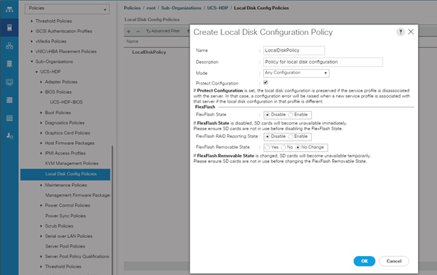
Create the Local Disk Configuration Policy
To create local disk configuration in the Cisco UCS Manager GUI, follow these steps:
1. Select the Servers tab on the left pane in the Cisco UCS Manager GUI.
2. Select Policies > root > Sub-Organization > UCS-MapR > Local Disk Config Policies
3. Right-click Local Disk Config Policies and Select Create Local Disk Config Policies.
4. Enter UCS-Boot as the local disk configuration policy name.
5. Change the Mode to Any Configuration. Check the Protect Configuration box.
6. Keep the FlexFlash State field as default (Disable).
7. Keep the FlexFlash RAID Reporting State field as default (Disable).
8. Click OK to complete the creation of the Local Disk Configuration Policy.
9. Click OK.
Figure 36 Create Local Disk Configuration Policy
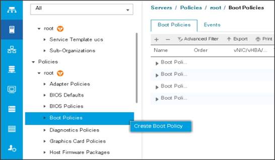
Create Boot Policy
To create boot policies within the Cisco UCS Manager GUI, follow these steps:
1. Select the Servers tab in the left pane in the Cisco UCS Manager GUI.
2. Select Policies > root.
3. Right-click the Boot Policies.
4. Select Create Boot Policy.
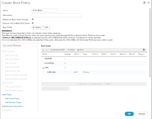
5. Enter ucs for the boot policy name.
6. (Optional) enter a description for the boot policy.
7. Keep the Reboot on Boot Order Change check box unchecked.
8. Keep Enforce vNIC/vHBA/iSCSI Name check box checked.
9. Keep Boot Mode Default (Legacy).
10. Expand Local Devices > Add CD/DVD and select Add Local CD/DVD.
11. Expand Local Devices and select Add Local Disk.
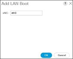
12. Expand vNICs and select Add LAN Boot and enter eth0.
13. Click OK to add the Boot Policy.
14. Click OK.
Figure 37 Create Boot Policy for Cisco UCS Server
Configure and Create a Service Profile Template
Service profile template enables policy based server management that helps ensure consistent server resource provisioning suitable to meet predefined workload needs.
Create Service Profile Template
To create a service profile template, follow these steps:
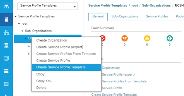
1. In the Cisco UCS Manager, go to Servers > Service Profile Templates > root Sub Organization > FlashStack-CVD > and right-click to “Create Service Profile Template” as shown below.
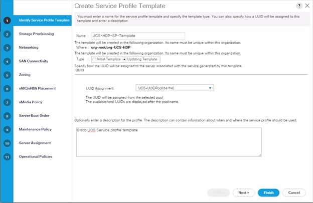
2. Enter the Service Profile Template name, for Type select Updating Template, and select the UUID Pool that was created earlier. Click Next.
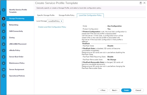
3. Select Local Disk Configuration Policy tab and select Local Storage policy from the drop-down list.
4. In the networking window, select Expert and click Add to create vNICs. Add one or more vNICs that the server should use to connect to the LAN.
5. In the create vNIC menu as vNIC name.
6. Select vNIC Template as vNIC0 and Adapter Policy as Linux.
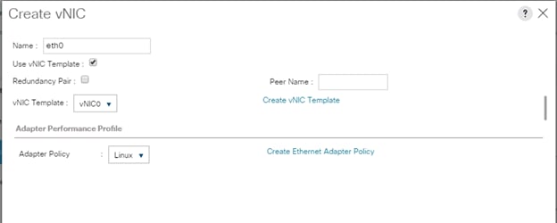
![]() Optionally, Network Bonding can be setup on the vNICs for each host for redundancy, as well as for increased throughput.
Optionally, Network Bonding can be setup on the vNICs for each host for redundancy, as well as for increased throughput.
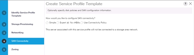
7. In the SAN Connectivity menu, select no vHBAs.
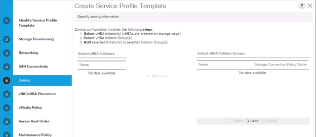
8. Click Next on the Zoning tab.
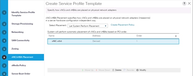
9. Select Let System Perform Placement for vNIC/vHBA Placement, click Next.
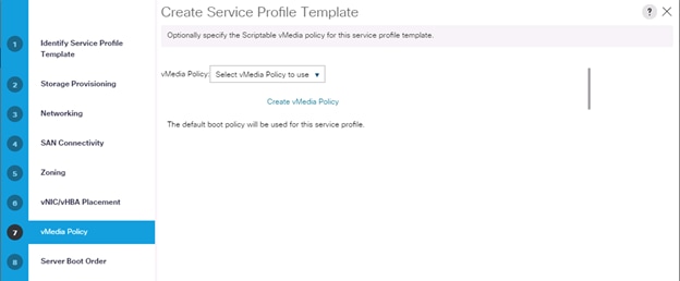
10. Click Next on vMedia Policy.
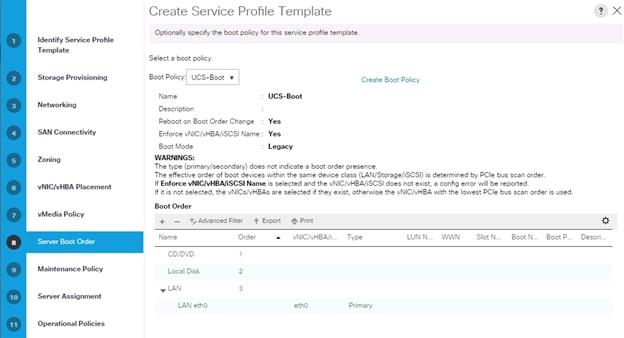
11. Select Boot Policy on the Server Boot Order tab.
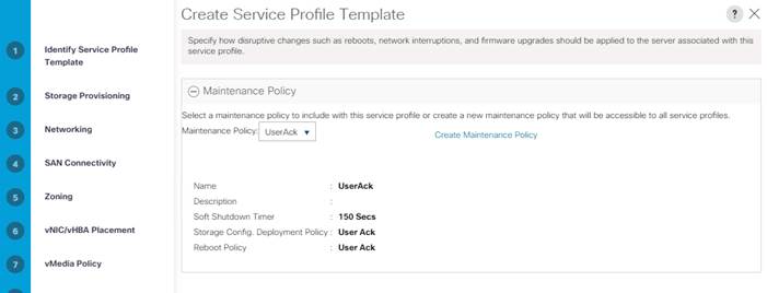
12. Select UserAck maintenance policy, that requires user acknowledgement prior to rebooting the server when making changes to the policy or pool configuration tied to a service profile.
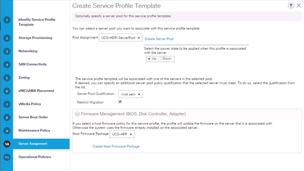
13. Select Server Pool policy to automatically assign service profile to a server that meets the requirement for server qualification based on the pool configuration. Select Power state when Service Profile is associated to server.
14. On the same page, you can configure the Host firmware Package Policy which helps to keep the firmware in sync when associated to server.
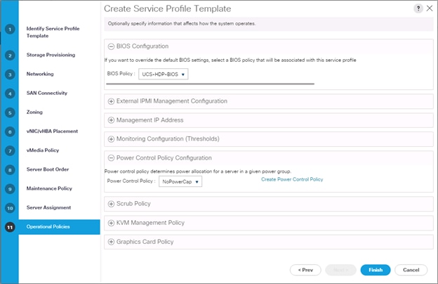
15. On the Operational Policy page, we configured the BIOS policy for the Cisco UCS C240 M5 Rack Server, Power Control Policy with NoPowerCap for maximum performance.
16. Click Finish to create the service profile template.
Create Service Profile from Template
To create service profiles from template, follow these steps:
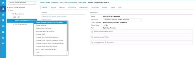
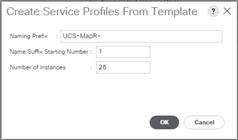
1. Right-click Service Profile Template select create Service profile from Template.
Figure 38 Create Service Profile from Template
Install SUSE Linux Enterprise Server 12 SP3
This section explains how to install SUSE Linux Enterprise Server using Software RAID (OS based Mirroring) on Cisco UCS C240 M5 servers. There are multiple ways to install the SUSE operating system. The installation procedure described in this deployment guide uses KVM console and virtual media from Cisco UCS Manager.
![]() In this study, SUSE version 12 SP3 DVD/ISO was utilized for the OS the installation on Cisco UCS C240 M5 Rack Servers.
In this study, SUSE version 12 SP3 DVD/ISO was utilized for the OS the installation on Cisco UCS C240 M5 Rack Servers.
To install the SUSE Linux Enterprise Server 12 SP3 operating system, follow these steps:
1. Log into the Cisco UCS Manager.
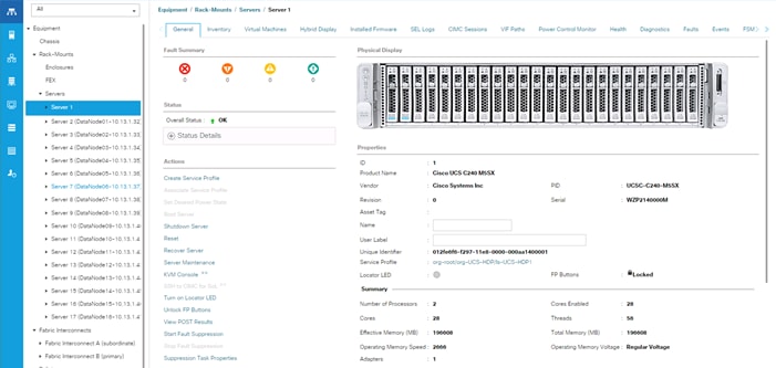
2. Select the Equipment tab.
3. In the navigation pane expand Rack-Mounts and then Servers.
4. Right-click the server and select KVM console.
5. In the right pane, click the KVM Console >>.
6. Click the link to launch the KVM console.
7. You will see the following:
KVM server certificate has been accepted. Click this link to continue loading the KVM client application: https://10.13.1.10/app/4_0_1c/kvm.html?&kvmIpAddr=10.13.1.166
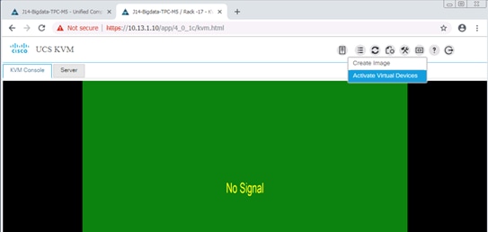
8. Point the cursor over the top right corner, select the Virtual Media tab.
9. Click the Activate Virtual Devices found in Virtual Media tab.
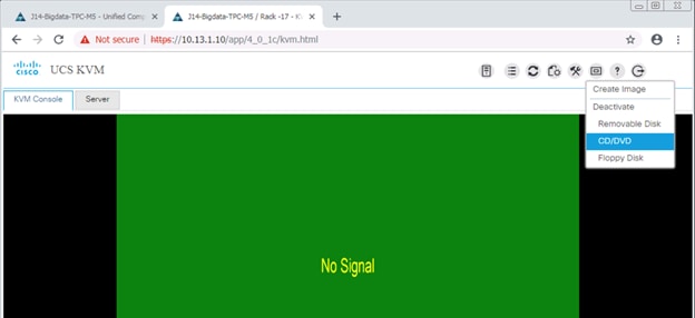
10. Click the Virtual Media tab to select CD/DVD.
11. Select Map Drive in the Virtual Disk Management window.
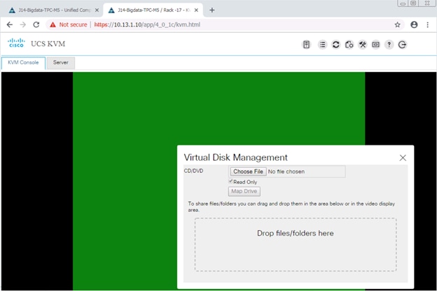
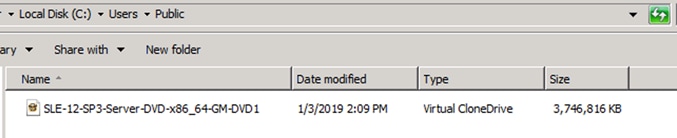
12. Browse to the SUSE Enterprise Linux 12 SP3 installer ISO image file.
![]() The SUSE Enterprise Linux 12 SP3 Server DVD is assumed to be on the client machine.
The SUSE Enterprise Linux 12 SP3 Server DVD is assumed to be on the client machine.
13. Click Open to add the image to the list of virtual media.
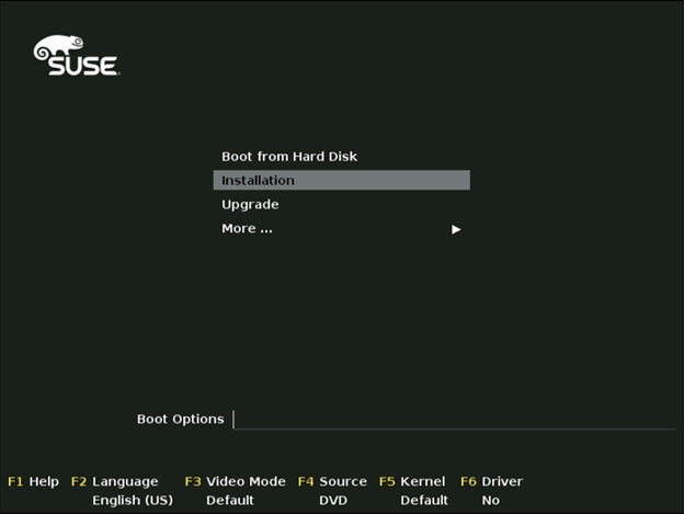
14. Select the Installation option from SUSE Linux Enterprise Server 12 SP3.
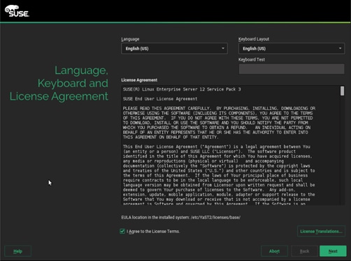
15. Agree to the End User License Agreement and select Next.
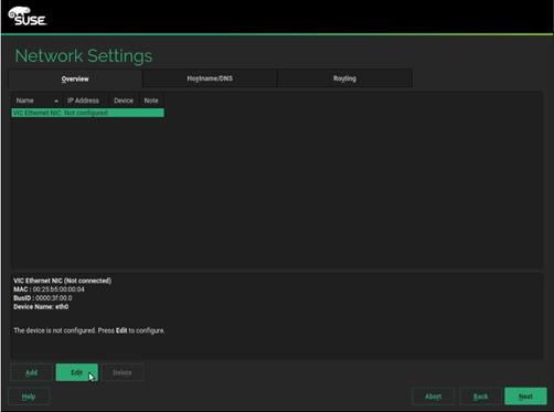
16. For the Network Settings stage, select Edit to configure the desired network interface.
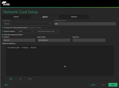
17. On the Network Card Setup Address tab, provide the assigned IP Address and Subnet Mask, then click Next.
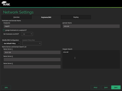
18. On the Hostname/DNS tab, enter the Hostname, Domain Name, Name Server(s) and Domain Search settings.
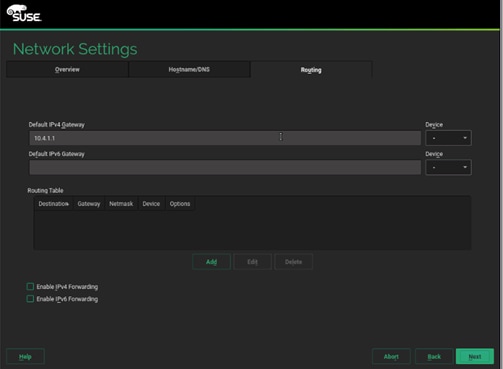
19. On the Routing tab, enter the Default IPv4 Gateway, then click Next.
20. On the Registration stage, if you already have an available subscription, enter your SUSE Customer Center email address and the registration code, then select Next. Otherwise, select Skip Registration and then click Next (A post-install registration can be done using the YaST tool).
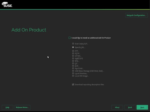
21. On the Add-on Product stage, click Next.
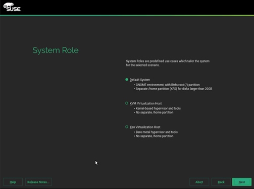
22. On the System Role stage, select Default System and then click Next.
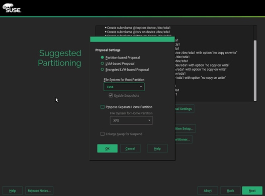
23. On the Suggest Partitioning stage, select Edit Proposal Settings.
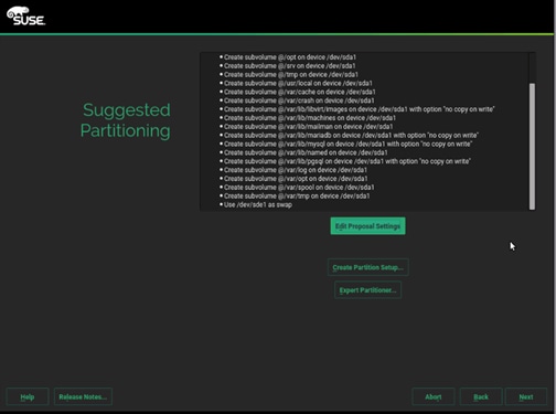
24. Uncheck Propose Separate Home Partition and then click OK.
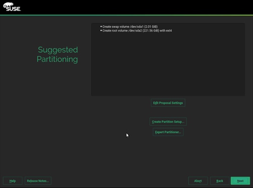
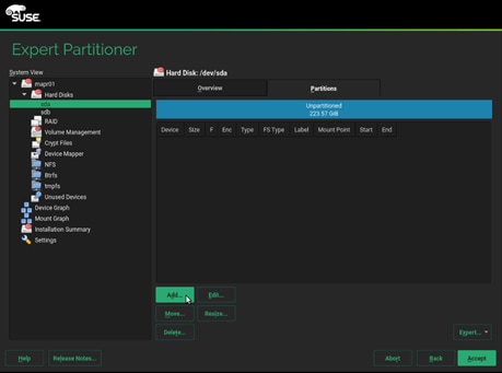
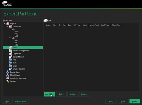
25. To setup the software RAID1 operating system volumes, use the Expert Partitioner.
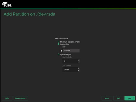
26. In the Hard Disks View, for the each of the two operating system drives, add the following three partitions, as a Primary Partition, of the designated size, as a Raw Volume (unformatted), with the OxFD Linux RAID type.
a. Select disk sda, click Add.
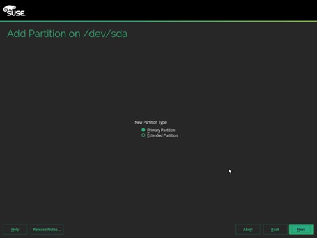
b. Select custom size and enter size as 2048MB. Click Next.
c. Select Role as Operating system.
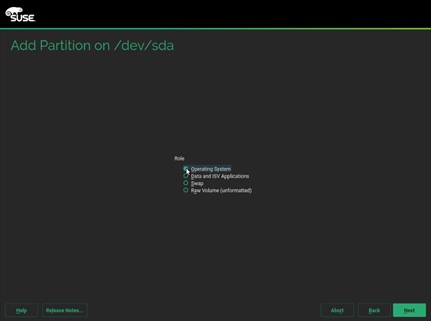
d. Follow the steps to create two more partition. One for swap and other for Data and ISV Applications with size as 2048MB and maximum size respectively.
27. Repeat steps a-d to create three partitions mentioned above on disk sdb.
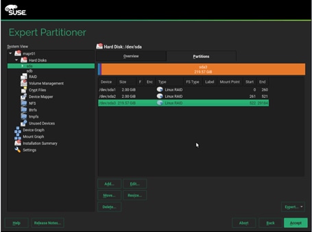
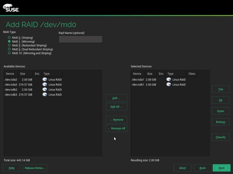
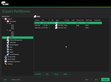
28. Once this is completed across both drives, in the RAID View, add the matching partitions from each disk, as a RAID1 (Mirroring) type.
29. Select RAID 1 and sda1 and sdb1 which are the matching partition for boot on disk sda and sdb.
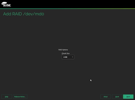
30. Default 4KiB as chunk size, click Next.
31. Select the appropriate Role. We created md0 for boot, md1 for swap and md2 for Data and ISV Applications.
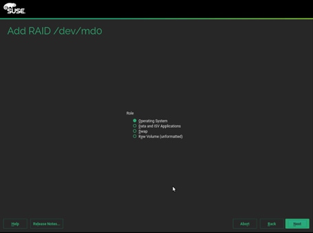
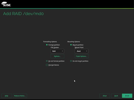
32. Format the partition with ext4 as file system and /boot mount partition. Mount and format as shown below for the three partitions created.
Operating System - Ext4 - /boot (partition1 – md0)
Swap - swap - swap (partition2 – md1)
Data and ISV Applications - Ext4 - / (partition 3 – md1)
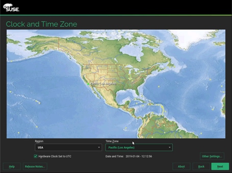
33. On the Clock and Time Zone stage, select the desired Region, Time Zone, then select Other Settings (to configure the designated NTP server) and then click Next.
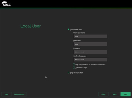
34. On the Local User stage, enter the User’s Full Name, Username and Password (twice), then click Next. The same password can be applied to the system administrator (root) account if that selection is made, otherwise a second screen will follow to ask for that account’s password.
35. To save time later, some adjustments can be made on the Installation Settings stage.
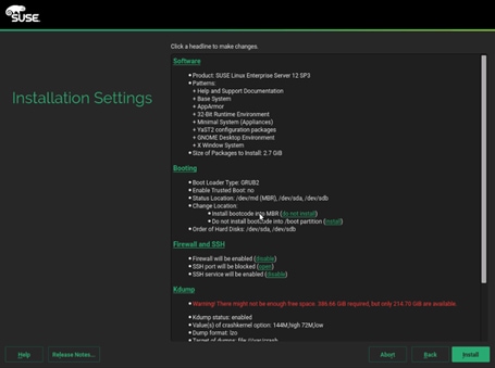
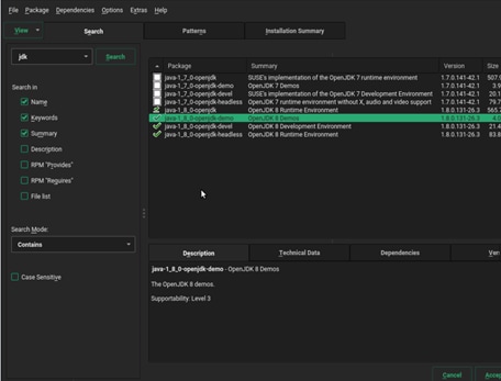
36. Select Software > Details > on the Search tab, enter “jdk” and Search, and check all the java-1_8_0-openjdk packages and click Accept and then click Continue.
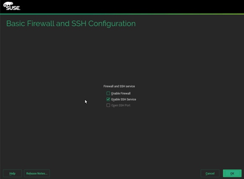
37. Select Firewall and SSH > Uncheck Enable Firewall, click OK.
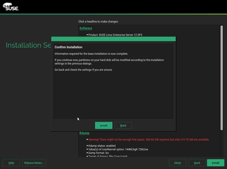
38. Click Install and then click Install in the popup window to confirm. The system reboots when done.
39. Repeat steps 1 to 38 to install SUSE Linux Enterprise Server 12 SP3 on Servers 2 through 28.
![]() The OS installation and configuration of the nodes that is mentioned above can be automated through PXE boot or third party tools.
The OS installation and configuration of the nodes that is mentioned above can be automated through PXE boot or third party tools.
The hostnames and their corresponding IP addresses are shown in Table 5.
Table 5 Hostnames and IP Address
| Hostname |
Eth0 |
| MapR01 |
10.4.1.31 |
| MapR02 |
10.4.1.32 |
| MapR03 |
10.4.1.33 |
| MapR04 |
10.4.1.34 |
| MapR05 |
10.4.1.35 |
| ….. |
….. |
| MapR27 |
10.4.1.57 |
| MapR28 |
10.4.1.58 |
Post OS Install Configuration
Choose one of the nodes of the cluster or a separate node as the Admin Node for management, such as MAPR installation, cluster parallel shell, creating a local SUSE repo and others. In this document, we use MapR01 for this purpose.
Set Up Passwordless Login
To manage all of the cluster nodes from the admin node password-less login needs to be setup. It assists in automating common tasks with clustershell (clush, a cluster wide parallel shell), and shell-scripts without using passwords.
When SUSE Linux Enterprise Server is installed across all the nodes in the cluster, to enable password-less login across all the nodes, follow these steps:
1. Log into the Admin Node (MapR01).
#ssh 10.4.1.31
2. Run the “ssh-keygen” command to create both public and private keys on the admin node.
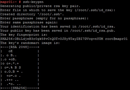
3. Run the following command from the admin node to copy the public key id_rsa.pub to all the nodes of the cluster. ssh-copy-id appends the keys to the remote-host’s. ssh/authorized_keys.
#for IP in {31..58}; do echo -n "$IP -> "; ssh-copy-id -i ~/.ssh/id_rsa.pub 10.4.1.$IP; done
![]()
4. Enter yes for Are you sure you want to continue connecting (yes/no)?
5. Enter the password of the remote host.
Configure /etc/hosts
Setup /etc/hosts on the Admin node; this is a pre-configuration to setup DNS as shown in the next section.
To create the host file on the admin node, follow these steps:
1. Populate the host file with IP addresses and corresponding hostnames on the Admin node (MapR01) and other nodes as follows:
a. On Admin Node (MapR01):
#vi /etc/hosts
#
# hosts This file describes a number of hostname-to-address
# mappings for the TCP/IP subsystem. It is mostly
# used at boot time, when no name servers are running.
# On small systems, this file can be used instead of a
# "named" name server.
# Syntax:
#
# IP-Address Full-Qualified-Hostname Short-Hostname
#
127.0.0.1 localhost
# special IPv6 addresses
::1 localhost ipv6-localhost ipv6-loopback
fe00::0 ipv6-localnet
ff00::0 ipv6-mcastprefix
ff02::1 ipv6-allnodes
ff02::2 ipv6-allrouters
ff02::3 ipv6-allhosts
10.4.1.31 MapR01
10.4.1.32 MapR02
10.4.1.33 MapR03
10.4.1.34 MapR04
10.4.1.35 MapR05
10.4.1.36 MapR06
10.4.1.37 MapR07
10.4.1.38 MapR08
………. ……..
………. ……..
………. ……..
10.4.1.57 MapR27
10.4.1.58 MapR28
Setting up ClusterShell
ClusterShell (or clush) is the cluster-wide shell that runs commands on several hosts in parallel. To set up the ClusterShell, follow these steps:
1. From the system connected to the Internet download Cluster shell (clush) and it’s dependencies:
wget https://download.opensuse.org/repositories/network:/cluster/SLE_12_SP3/noarch/clustershell-1.8.1-8.1.noarch.rpm
wget https://download.opensuse.org/repositories/network:/cluster/SLE_12_SP3/noarch/python2-clustershell-1.8.1-8.1.noarch.rpm
wget https://build.opensuse.org/package/binary/systemsmanagement:saltstack:products/python-PyYAML/SLE_12_SP3/x86_64/python-PyYAML-3.10-0.13.1.x86_64.rpm
2. Copy these packages to MapR01 then install them:
#zypper in -y ./clustershell-1.8.1-8.1.noarch.rpm ./python2-clustershell-1.8.1-8.1.noarch.rpm ./python-PyYAML-3.10-0.13.1.x86_64.rpm
3. Edit /etc/clustershell/groups.d/local.cfg file to include hostnames for all the nodes of the cluster. This set of hosts is taken when running clush with the ‘-a’ option.
#all: MapR[01-28]
4. For 28 node cluster as in our CVD, set groups file as follows:
a. On ClusterShell, go to: https://github.com/cea-hpc/clustershell/wiki/UserAndProgrammingGuide
![]() ClusterShell will not work if the passwordless ssh access to the target machine is not enabled (it is required to be enabled in the known_hosts file).
ClusterShell will not work if the passwordless ssh access to the target machine is not enabled (it is required to be enabled in the known_hosts file).
![]() A clush copy without –dest copies to the same directory location as the source-file directory.
A clush copy without –dest copies to the same directory location as the source-file directory.
5. Make sure DNS is working by running the following command on Admin node and any data-node.
[root@mapr22 ~]# host mapr01
mapr01.cms.net has address 10.4.1.31
![]() zypper install –y bind-utils needs to be run for host utility to run.
zypper install –y bind-utils needs to be run for host utility to run.
![]() Please refer to the SUSE Linux Enterprise Server administration documentation guide for more information: https://www.suse.com/documentation/sles-12/book_sle_admin/data/cha_dns.html.
Please refer to the SUSE Linux Enterprise Server administration documentation guide for more information: https://www.suse.com/documentation/sles-12/book_sle_admin/data/cha_dns.html.
Upgrade the Cisco Network Driver for VIC1387
The latest Cisco Network driver is required for performance and updates. You can download the latest drivers be from the link below: https://software.cisco.com/download/home/286318800/type/283291009/os/SLES%2012%20SP3/release/4.0%25281a%2529
To upgrade the Cisco Network driver for VIC1387, follow these steps:
1. In the ISO image for Linux drivers, the required cisco-enic-usnic-kmp-default-3.0.144.37_k4.4.73_5-595.52.x86_64.rpm can be located at \Network\Cisco\VIC\SLES\SLES12.3
2. From a node connected to the Internet, download, extract and transfer cisco-enic-usnic-kmp-default-3.0.144.37_k4.4.73_5-595.52.x86_64.rpm to MapR01 (admin node – MapR01, in our example).
3. Install the rpm on all nodes of the cluster using the following clush commands. For this example, the rpm is assumed to be in present working directory of MapR01.
# clush -a -b -c cisco-enic-usnic-kmp-default-3.0.144.37_k4.4.73_5-595.52.x86_64.rpm
# clush -a -b “rpm -ivh cisco-enic-usnic-kmp-default-3.0.144.37_k4.4.73_5-595.52.x86_64.rpm "
4. Make sure that the above installed version of kmod-enic driver is being used on all nodes by running the command "modinfo enic" on all nodes.
# clush -a -B "modinfo enic | head -5"
5. Also it is recommended to download the megaraid driver for higher performance , the RPM can be found in the same package at \Storage\Cisco\VIC\SLES\SLES12.3
#clush -a -b -c lsi-megaraid_sas-kmp-default-07.703.06.00_sles12sp3-1.x86_64.rpm
#clush -a -b "rpm -ivh lsi-megaraid_sas-kmp-default-07.703.06.00_sles12sp3-1.x86_64.rpm"
6. Make sure that the above installed version of kmod-enic driver is being used on all nodes by running the command "modinfo enic" on all nodes.
# clush -a -B "modinfo megariad_sas | head -5”
Enable Syslog
Syslog must be enabled on each node to preserve the logs pertaining to killed processes or failed jobs. Modern versions such as syslog-ng and rsyslog are possible, making it more difficult to be certain that a syslog daemon is present. To confirm that the service is properly configured, run on of the following commands:
#clush -B -a rsyslogd –v
#clush -B -a service rsyslog status
Set ulimit
On each node, ulimit -n specifies the number of inodes that can be simultaneously opened. With the default value of 1024, the system appears to be out of disk space and shows no inodes available. This value should be set to 64000 on every node.
![]() Higher values are unlikely to result in an appreciable performance gain.
Higher values are unlikely to result in an appreciable performance gain.
To set the ulimit, follow these steps:
1. To set the ulimit on SUSE, edit /etc/security/limits.conf on admin node MapR01 and add the following lines:
root soft nofile 64000
root hard nofile 64000
![]()
2. Copy the /etc/security/limits.conf file from admin node (MapR01) to all the nodes using the following command.
#clush -a -b -c /etc/security/limits.conf --dest=/etc/security/
3. Edit the /etc/pam.d/common-session* files to make sure the following entry is present:
# end of pam-auth-update config
session required pam_limits.so
![]() The ulimit values are applied on a new shell; running the command on a node on an earlier instance of a shell will display old values.
The ulimit values are applied on a new shell; running the command on a node on an earlier instance of a shell will display old values.
Set TCP Retries
Adjusting the tcp_retries parameter for the system network enables faster detection of failed nodes. Given the advanced networking features of Cisco UCS, this is a safe and recommended change (failures observed at the operating system layer are most likely serious rather than transitory).
![]() On each node set the number of TCP retries to 5; this can help detect unreachable nodes with less latency.
On each node set the number of TCP retries to 5; this can help detect unreachable nodes with less latency.
To set the TCP retries, follow these steps:
1. Edit the file /etc/sysctl.conf and on admin node MapR01 and add the following lines:
net.ipv4.tcp_retries2=5
2. Copy the /etc/sysctl.conf file from admin node (MapR01) to all the nodes using the following command:
#clush -a -b -c /etc/sysctl.conf --dest=/etc/
3. Load the settings from default sysctl file /etc/sysctl.conf by running.
#clush -B -a sysctl -p
Reduce Swapping
To reduce swapping, follow these steps:
1. In order to reduce Swapping, run the following on all nodes. Variable vm.swappiness defines how often swap should be used, 60 is default.
#clush -a -b " echo 'vm.swappiness=1' >> /etc/sysctl.conf"
2. Load the settings from the default sysctl file /etc/sysctl.conf.
#clush –a –b "sysctl –p"
Disable Memory Overcommit
![]() Using overcommit is not recommended because it can lead to the kernel memory manager stopping processes to free memory, resulting in stopped MapR processes and system instability. Set “vm.overcommit_memory” to 0.
Using overcommit is not recommended because it can lead to the kernel memory manager stopping processes to free memory, resulting in stopped MapR processes and system instability. Set “vm.overcommit_memory” to 0.
To disable memory overcommit, follow these steps:
1. Edit the file /etc/sysctl.conf and add the following line:
#clush -a -b " echo 'vm.overcommit_memory=0' >> /etc/sysctl.conf"
2. Save the file and run:
#clush -a -b “sysctl -p”
![]() You can try MapR on non-production equipment, but under the demands of a production environment, memory needs to be balanced against disks, network, and CPU.
You can try MapR on non-production equipment, but under the demands of a production environment, memory needs to be balanced against disks, network, and CPU.
Disable Transparent Huge Pages
Disabling Transparent Huge Pages (THP) reduces elevated CPU usage caused by THP. Run the following commands:
#clush -a -b "echo never > /sys/kernel/mm/transparent_hugepage/enabled”
#clush -a -b "echo never > /sys/kernel/mm/transparent_hugepage/defrag"
1. The commands (above) must be run for every reboot, so copy this command to /etc/rc.local so they are executed automatically for every reboot.
2. On the Admin node, run the following commands:
#echo "echo never > /sys/kernel/mm/transparent_hugepage/enabled" >> /root/thp_disable
#echo "echo never > /sys/kernel/mm/transparent_hugepage/defrag " >> /root/thp_disable
3. Copy file to each node:
#clush –a –b –c /root/thp_disable
4. Append the content of file thp_disable to /etc/rc.local:
#clush -a -b “cat /root/thp_disable >> /etc/rc.local”
Disable IPv6 Defaults
To disable IPv6 defaults, follow these steps:
1. Disable IPv6 as the addresses used are IPv4.
#clush -a -b " echo 'net.ipv6.conf.all.disable_ipv6 = 1' >> /etc/sysctl.conf"
#clush -a -b " echo 'net.ipv6.conf.default.disable_ipv6 = 1' >> /etc/sysctl.conf"
#clush -a -b " echo 'net.ipv6.conf.lo.disable_ipv6 = 1' >> /etc/sysctl.conf"
2. Load the settings from default sysctl file /etc/sysctl.conf.
#clush –a –b "sysctl –p”
Configure Data Drives on Data Nodes
To configure non-OS disk drives as RAID0 using StorCli command, follow these steps:
![]() These volumes are going to be used for MapRFS (HDFS supported) Data.
These volumes are going to be used for MapRFS (HDFS supported) Data.
1. Download storcli from the link: https://www.broadcom.com/support/download-search/?pg=&pf=&pn=&po=&pa=&dk=storcli
2. Extract the zip file and copy storcli-007.0709.0000.0000-1.noarch.rpm from the linux directory.
3. Download storcli and its dependencies and transfer to Admin node.
#scp storcli-007.0709.0000.0000-1.noarch.rpm MapR01:/root/
4. Copy storcli rpm to all the nodes using the following commands:
#clush -a -b -c /root/storcli-007.0709.0000.0000-1.noarch.rpm --dest=/root/
5. Run the following command to install storcli on all the nodes.
#clush -a -b “zypper install -y /root/storcli-007.0709.0000.0000-1.noarch.rpm”
6. Run the below command to copy storcli64 to root directory.
#cd /opt/MegaRAID/storcli/
#cp storcli64 /root/
7. Copy storcli64 to all the nodes using the following commands.
#clush -a -b -c /root/storcli64 --dest=/root/
8. Run the following command to get enclosure id.
# clush -a -B ./storcli64 /c0 show all| awk '{print $1}'| sed -n '/[0-9]:[0-9]/p'|awk '{print substr($1,1,2)}'|sort -u
![]()
9. Verify status of the drives is “UGood (Unconfigured good)” as shown in the screenshot below.
# clush -a -b "./storcli64 /c0 /e66 /sall show"
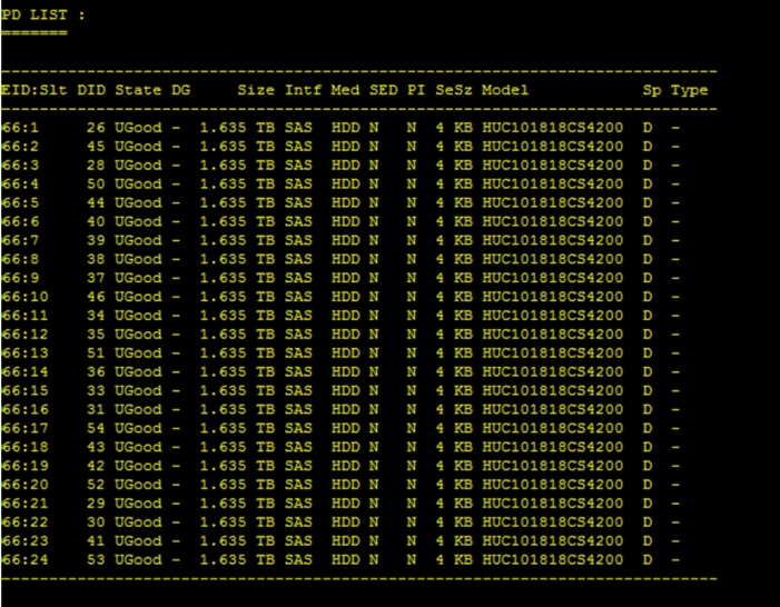
10. Run the following command from the admin node to create the virtual drives with individual RAID 0 configurations on all the data nodes.
Reference #clush -a -B ./storcli64 /c0 add vd (Raid0) drives=(EnclosureID):{Slot(x-y)} wb ra Strip=(StripSize)
#clush –a -B ./storcli64 /c0 add vd each r0 drives=66:1-24 wb ra Strip=1024
11. Verify drive status is changed to Onln (Online) and virtual drive status to Optl (Operational) after command is executed successfully as shown in the screenshot below.
# clush -a -b "./storcli64 /c0 /sall show"
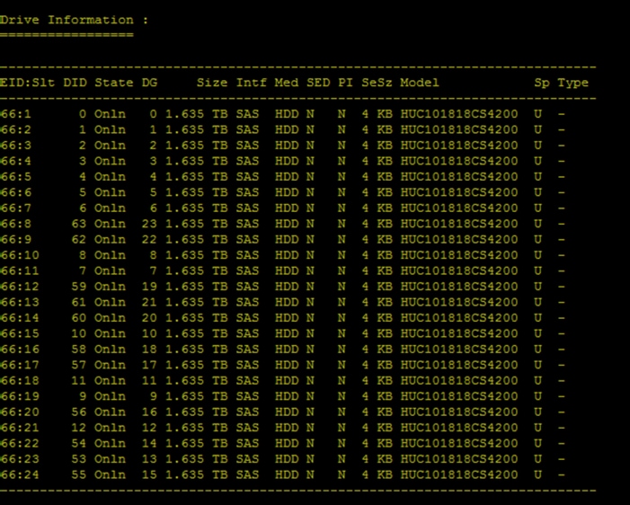
12. # clush -a -b "./storcli64 /c0 /vall show"
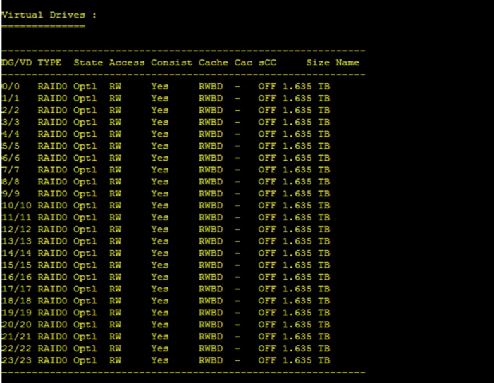
13. Alternatively, you can create a script as shown below with the commands to set the status for “Read Cache” and “Write Cache” as “Read Ahead” and “Write Back.”
#vi raid0.sh
./storcli64 /c0 add vd each r0 drives=66:1-24 wb ra Strip=1024
./storcli64 /c0 /vall set rdcache=ra
./storcli64 /c0 /vall set wrcache=wb
./storcli64 /c0 /vall set autobgi=on
14. Disk configuration status via “lsblk | grep ^sd” on MapR nodes.
#clush -a -B ‘lsblk | grep ^sd’
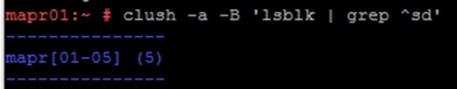
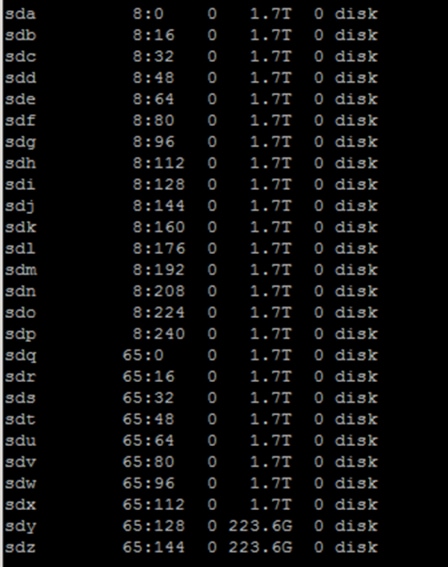
15. State can also be verified in UCSM as show below in Equipment>Rack-Mounts>Servers>Server # under Inventory/Storage/Disk tab.
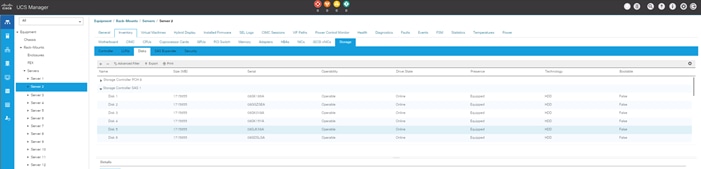
![]() Create Raid 1 for the MAPR Data Science Refinery nodes as shown as management nodes.
Create Raid 1 for the MAPR Data Science Refinery nodes as shown as management nodes.
Run the Cluster Verification Script
This section describes how to create the script “cluster_verification.sh” that verifies the CPU, memory, NIC, and storage adapter settings across the cluster on all nodes. This script also checks additional prerequisites such as NTP status, SELinux status, ulimit settings, JAVA_HOME settings and JDK version, IP address and hostname resolution, Linux version and firewall settings.
To run the cluster verification script, follow these steps:
1. Create the script cluster_verification.sh on the Admin node (MapR01), as shown below.
#vi cluster_verification.sh
#!/bin/bash
shopt -s expand_aliases,
# Setting Color codes
green='\e[0;32m'
red='\e[0;31m'
NC='\e[0m' # No Color
echo -e "${green} === Cisco UCS Integrated Infrastructure for Big Data and Analytics \ Cluster Verification === ${NC}"
echo ""
echo ""
echo -e "${green} ==== System Information ==== ${NC}"
echo ""
echo ""
echo -e "${green}System ${NC}"
clush -a -B " `which dmidecode` |grep -A2 '^System Information'"
echo ""
echo ""
echo -e "${green}BIOS ${NC}"
clush -a -B " `which dmidecode` | grep -A3 '^BIOS I'"
echo ""
echo ""
echo -e "${green}Memory ${NC}"
clush -a -B "cat /proc/meminfo | grep -i ^memt | uniq"
echo ""
echo ""
echo -e "${green}Number of Dimms ${NC}"
clush -a -B "echo -n 'DIMM slots: '; `which dmidecode` |grep -c \ '^[[:space:]]*Locator:'"
clush -a -B "echo -n 'DIMM count is: '; `which dmidecode` | grep \ "Size"| grep -c "MB""
clush -a -B " `which dmidecode` | awk '/Memory Device$/,/^$/ {print}' |\ grep -e '^Mem' -e Size: -e Speed: -e Part | sort -u | grep -v -e 'NO \ DIMM' -e 'No Module Installed' -e Unknown"
echo ""
echo ""
# probe for cpu info #
echo -e "${green}CPU ${NC}"
clush -a -B "grep '^model name' /proc/cpuinfo | sort -u"
echo ""
clush -a -B "`which lscpu` | grep -v -e op-mode -e ^Vendor -e family -e\ Model: -e Stepping: -e BogoMIPS -e Virtual -e ^Byte -e '^NUMA node(s)'"
echo ""
echo ""
# probe for nic info #
echo -e "${green}NIC ${NC}"
clush -a -B "`which ifconfig` | egrep '(^e|^p)' | awk '{print \$1}' | \ xargs -l `which ethtool` | grep -e ^Settings -e Speed"
echo ""
clush -a -B "`which lspci` | grep -i ether"
echo ""
echo ""
# probe for disk info #
echo -e "${green}Storage ${NC}"
clush -a -B "echo 'Storage Controller: '; `which lspci` | grep -i -e \ raid -e storage -e lsi"
echo ""
clush -a -B "dmesg | grep -i raid | grep -i scsi"
echo ""
clush -a -B "lsblk -id | awk '{print \$1,\$4}'|sort | nl"
echo ""
echo ""
echo -e "${green} ================ Software ======================= ${NC}"
echo ""
echo ""
echo -e "${green}Linux Release ${NC}"
clush -a -B "cat /etc/*release | uniq"
echo ""
echo ""
echo -e "${green}Linux Version ${NC}"
clush -a -B "uname -srvm | fmt"
echo ""
echo ""
echo -e "${green}Date ${NC}"
clush -a -B date
echo ""
echo ""
echo -e "${green}NTP Status ${NC}"
clush -a -B "ntpstat 2>&1 | head -1"
echo ""
echo ""
echo -e "${green}SELINUX ${NC}"
clush -a -B "echo -n 'SElinux status: '; grep ^SELINUX= \ /etc/selinux/config 2>&1"
echo ""
echo ""
clush -a -B "echo -n 'CPUspeed Service: '; `which service` cpuspeed \ status 2>&1"
clush -a -B "echo -n 'CPUspeed Service: '; `which chkconfig` --list \ cpuspeed 2>&1"
echo ""
echo ""
echo -e "${green}Java Version${NC}"
clush -a -B 'java -version 2>&1; echo JAVA_HOME is ${JAVA_HOME:-Not \ Defined!}'
echo ""
echo ""
echo -e "${green}Hostname LoOKup${NC}"
clush -a -B " ip addr show"
echo ""
echo ""
echo -e "${green}Open File Limit${NC}"
clush -a -B 'echo -n "Open file limit(should be >32K): "; ulimit -n'
# MapR related RPMs
clush -a -B 'rpm -qa | grep -i nfs |sort'
clush -a -B 'rpm -qa | grep -i nfs |sort'
clush -a -B 'echo Missing RPMs: ; for each in make patch lsb-release irqbalance syslinux hdparm sdparm dmidecode nc; do rpm -q $each | grep "is not installed"; done'
clush -a -B "ls -d /opt/mapr/* | head"
# mapr login
clush -a -B 'echo "mapr login "; getent passwd mapr'
clush -a -B 'echo "Root login "; getent passwd root'
exit
2. Change permissions to executable.
#chmod 755 cluster_verification.sh
3. Run the Cluster Verification tool from the admin node. This can be run before starting MapR to identify any discrepancies in Post OS Configuration between the servers or during troubleshooting of any cluster / MapR issues.
#./cluster_verification.sh
Micro-Benchmark Test
This section provides a set of micro-benchmarks and prerequisites scripts to verify that all the systems are configured correctly.
To verify the configuration across the cluster, follow these steps:
1. STREAM benchmark to test memory bandwidth.
2. RPCtest to test network bandwidth.
3. IOzone to test I/O.
![]() Running these tests is optional. Test results can vary based on topology and configuration.
Running these tests is optional. Test results can vary based on topology and configuration.
Run STREAM Benchmark
The STREAM benchmark measures sustainable memory bandwidth (in MB/s) and the corresponding computation rate for simple vector kernels. To download the STREAM benchmark, go to: http://www.cs.virginia.edu/stream/
To run the STREAM benchmark, follow these steps:
1. Log into the admin node. Copy and extract STREAM file to each node (/root/).
#clush -a -B -c stream.tgz
#clush -a -B "tar -xvf stream.tgz"
2. Run the following command to run the STREAM benchmark on all nodes:
#clush -B -a "/root/stream/runme.sh > /root/stream.log"
To verify the results, run the following commands:
1. Extract the five lines of the result as shown and verify it on all the nodes.
#clush -B -a "grep -A5 \"Function \" stream.log"
![]() Results can vary based on the configuration.
Results can vary based on the configuration.
Run MapR RPCtest
MapR RPCtest is a network bandwidth measurement test. In this solution, the methodology adopted to verify the network bandwidth across the cluster requires configuring half the nodes as senders and the remaining half as receivers. This test is included in the MapR software available at /opt/mapr/th/tools/rpctest as part of the installation.
To run the RPCtest, follow these steps:
1. Log into the admin node and run the following commands to create the script:
#!/bin/bash
# Use rpctest to validate network bandwidth for worst case, bisection
# One half of nodes (servers) sends load to other half and measures throughput
# MapR rpctest is client/server binary, use -h to see options
half1=(10.4.1.31 10.4.1.33 10.4.1.35 10.4.1.37 10.4.1.39 10.4.1.41 10.4.1.43 10.4.1.45)
for node in "${half1[@]}"; do
ssh -n $node /opt/mapr/server/tools/rpctest -server &
done
sleep 9 # let the servers set up
# Define 2nd array of client hosts (other half of all hosts in cluster)
half2=(10.4.1.32 10.4.1.34 10.4.1.36 10.4.1.38 10.4.1.40 10.4.1.42 10.4.1.44 10.4.1.46)
i=0
for node in "${half2[@]}"; do
ssh -n $node "/opt/mapr/server/tools/rpctest -client 5000 ${half1[$i]} > rpctest.log" &
((i++))
done
wait $!
sleep 5
tmp=${half1[@]}
clush -w ${tmp// /,} pkill rpctest
2. Run the runRPCtest.sh command from the admin node.
3. Results are generated on receiver nodes. Verify the results for all nodes.
clush -B -w 10.4.1.[32,34,36,38,40,42,44,46,48,50,52,54,56,58] cat rpctest.log
Run IOzone Benchmark
IOzone is a filesystem benchmark that measures the performance of various I/O operations, such as read, write, re-read, re-write, fread, fwrite, random read and random write.
![]() IOzone is data destructive. Do not run the test on disks with data.
IOzone is data destructive. Do not run the test on disks with data.
To run the IOzone benchmark test, follow these steps:
1. Download IOzone from http://www.iozone.org/ and copy it to all nodes at /root/.
2. Create the following script; run IOzone.sh on the admin node.
#!/bin/bash
# Parallel IOzone tests to stress/measure disk controller
# These tests are destructive therefore
# Test must be run BEFORE MapR filesystem is formatted with disksetup
# Run iozone command once on a single device to verify iozone command
D=$(dirname "$0")
abspath=$(cd "$D" 2>/dev/null && pwd || echo "$D")
# run iozone with -h option for usage, adjust path below for iozone location
# Set list of device names for the 'for' loop
lsblk -id | grep -o ^sd. | sort > /tmp/iozone.disks
for i in `lsblk -i | grep -B2 md[0-1] | grep -v '-' | awk '{print $1}'`; do sed -i "/$i/d" /tmp/iozone.disks; done
disks=`cat /tmp/iozone.disks | xargs`
echo $disks
set -x
for disk in $disks; do
echo $abspath/iozone -I -r 1M -s 80G -i 0 -i 1 -i 2 -f /dev/$disk > $disk-iozone.log&
sleep 3 #Some controllers seem to lockup without a sleep
done
3. Copy runIOzone.sh to all the nodes at location /root/.
#clush -a -B -c runIOzone.sh
4. Run the following command to start the test:
#clush -a -B runIOzone.sh
5. Verify that the tests are running and wait for its completion.
#clush -a -B "ps -aef | grep iozone | wc -l"
---------------
MapR[01-28] (28)
---------------
6. Run the following command to verify the test results.
![]() The test result is generated for each disk as sd<x>-iozone.log, where <x> is the device id. These logs have sequential and random write and read latencies from each disks.
The test result is generated for each disk as sd<x>-iozone.log, where <x> is the device id. These logs have sequential and random write and read latencies from each disks.
# grep " 83886080 " sd*.log
![]() Results can vary based on configuration.
Results can vary based on configuration.
Install MapR
Installation of MapR software across the cluster involves performing several steps on each node. To make the installation process simpler, start with the installation of core MapR components such as CLDB, MapR-FS, NFS gateway and Yarn. Any additional Hadoop ecosystem components can be easily installed by following instructions on http://doc.mapr.com/display/MapR/Ecosystem+Guide. This section will follow the Table 6 role assignments for installation of services on the 64-node cluster.
The following sections explain the steps and options to install MapR software:
· Preparing Packages and Repositories
· MapR Installation
· Installing MapR packages
· Verify successful installation
· Configure the Node with the configure.sh Script
· Formatting Disks with the disksetup Script
Plan the Cluster
The first step towards deploying the MapR is planning which nodes contribute to the cluster and selecting the services that will run on each node.
The MapR 6.1 Installation planning guide: https://mapr.com/docs/61/AdvancedInstallation/PlanningtheCluster.html
MapR Services
In a typical cluster, most nodes are dedicated to data processing and storage, and a smaller number of nodes run services that provide cluster coordination and management. Some applications run on cluster nodes and others run on client nodes that can communicate with the cluster.
Table 6 lists some of the services that can be run on a node and describes the MapR services.
| Service |
Description |
| Warden |
Warden runs on every node, coordinating the node's contribution to the cluster. |
| TaskTracker (optional) |
Hadoop TaskTracker starts and tracks MapReduce tasks on a node. The TaskTracker service receives task assignments from the JobTracker service and manages task execution. |
| NodeManager |
Hadoop YARN NodeManager service. The NodeManager manages node resources and monitors the health of the node. It works with the ResourceManager to manage YARN containers that run on the node. |
| FileServer |
FileServer is the MapR service that manages disk storage for MapR-FS and MapR-DB on each node. |
| CLDB |
Maintains the container location database (CLDB) service. The CLDB service coordinates data storage services among MapR-FS FileServer nodes, MapR NFS gateways, and MapR clients. |
| NFS |
Provides read-write MapR Direct Access NFS access to the cluster, with full support for concurrent read and write access. |
| MapR HBase Client (optional) |
Provides access to MapR-DB tables via HBase APIs. Required on all client nodes that will access table data in MapR-FS |
| JobTracker (optional) |
Hadoop JobTracker service. The JobTracker service coordinates the execution of MapReduce jobs by assigning tasks to TaskTracker nodes and monitoring task execution. |
| ResourceManager |
Hadoop YARN ResourceManager service. The ResourceManager manages cluster resources, and tracks resource usage and node health. |
| ZooKeeper |
Enables high availability (HA) and fault tolerance for MapR clusters by providing coordination. |
| HistoryServer |
Archives MapReduce job metrics and metadata. |
| Web Server |
Runs the MapR Control System. |
| Hue
|
Hue is Hadoop user interface that interacts with Apache Hadoop and its ecosystem components, such as Hive, Pig, and Oozie. |
| Pig |
Pig is a high-level data-flow language and execution framework. |
| Hive |
Hive is a data warehouse that supports SQL-like ad hoc querying and data summarization. |
| Flume |
Flume is a service for aggregating large amounts of log data |
| Oozie |
Oozie is a workflow scheduler system for managing Hadoop jobs. |
| Spark |
Spark is an processing engine for large datasets. |
| Sqoop |
Sqoop is a tool for transferring bulk data between Hadoop and relational databases. |
| Warden |
Warden runs on every node, coordinating the node's contribution to the cluster. |
Node Types
The MapR installer categorizes nodes as control nodes (which runs only cluster management services to manage the cluster), data nodes, control-as-data nodes (which combine the functions of control and data nodes), or client nodes. For deployment of MapR on Cisco UCS Integrated Infrastructure for Big Data, control services co-exist on data nodes (control-as-data node) as control services have a small footprint. The client node can be any node accessing the MapR cluster (all nodes in the MapR cluster are also client nodes)
Table 7 Node Types and Role Description
| Node Type |
Description |
| Data Node |
Used for processing data, so they have the FileServer and TaskTracker services installed. If MapR-DB or HBase is run on a data node, the HBase Client service is also installed. Data nodes are used for running YARN applications and MapReduce jobs, and for storing file and table data. These nodes run the FileServer service along with NodeManager (for YARN nodes), TaskTracker (for MapReduce nodes), and HBase client (for MapR-DB and HBase nodes). |
| Control-as-Data-Node |
Acts as both control and data nodes. They perform both functions and have both sets of services installed. |
| Client Node |
Provides access to the cluster so the user can communicate via the command line or the MapR Control System. Client nodes provide access to each node on the cluster so the user can submit jobs and retrieve data. A client node can be an edge node of the cluster, laptop, or any Windows machine. |
Node Types and Associated Services
Table 8 lists which services are assigned to each node type. When deploying MapR on Cisco UCS Integrated Infrastructure for Big Data, all Control Node services are deployed on Control-as-data node. There are no nodes running purely as control nodes as they also run data node services
Table 8 MapR Nodes and Associated Services
| Node Type |
YARN Main Services |
Core MapR Services |
Additional MRv1 Services |
Additional HBase Service |
| Control-as-data node |
ResourceManager (RM) HistoryServer (HS) NodeManager (NM) |
CLDB ZooKeeper FileServer NFS Webserver FileServer |
JobTracker (optional) TaskTracker (optional) |
|
| Data node |
NodeManager (NM) |
FileServer |
TaskTracker (optional) |
|
| Client node |
|
|
MapR Client |
HBase Client (optional) |
Hostnames and Roles
This section explains the cluster plan of a 64-node cluster with hostnames and roles assignments for the following services as listed in Table 9.
· ResourceManager (RM)
· HistoryServer (HS)
· NodeManager (NM)
· TaskTracker (TT, optional)
· JobTracker (JT, optional), FileServer (FS)
· Container Location Database (CLDB)
· Zookeeper
· Webserver
![]() Starting with MapR version 4.0, both Yarn and MapReduce V1 are supported in the same cluster and on the same node.
Starting with MapR version 4.0, both Yarn and MapReduce V1 are supported in the same cluster and on the same node.
Table 9 Host Names and Role Assignment
| Rack01 – Host Name |
MapR Roles |
Rack02 – Host Name |
MapR Roles |
| MAPR01 |
Core, FS, NFS, NM, HS |
MAPR17 |
Core, FS, NFS, NM |
| MAPR02 |
Core, FS, NFS, NM, WS |
MAPR18 |
Core, CLDB, ZooKeeper, FS |
| MAPR03 |
Core, FS, NFS, NM, RM |
MAPR19 |
Core, FS, NFS, NM, HS |
| MAPR04 |
Core, FS, NFS, NM |
MAPR20 |
Core, FS, NFS, NM, WS |
| MAPR05 |
Core, FS, NFS, NM |
MAPR21 |
Core, FS, NFS, NM, RM |
| MAPR06 |
Core, FS, NFS, NM |
MAPR22 |
Core, FS, NFS, NM |
| MAPR07 |
Core, FS, NFS, NM |
MAPR23 |
Core, FS, NFS, NM |
| MAPR08 |
Core, FS, NFS, NM |
MAPR24 |
Core, FS, NFS, NM |
| MAPR09 |
Core, CLDB, ZooKeeper, FS |
MAPR25 |
Core, FS, NFS, NM |
| MAPR10 |
Core, FS, NFS, NM, HS |
MAPR26 |
Core, FS, NFS, NM |
| MAPR11 |
Core, FS, NFS, NM, WS |
MAPR27 |
Core, CLDB, ZooKeeper, FS, HS |
| MAPR12 |
Core, FS, NFS, NM, RM |
MAPR28 |
Core, FS, NFS, NM |
| MAPR13 |
Core, FS, NFS, NM |
|
|
| MAPR14 |
Core, FS, NFS, NM |
|
|
| MAPR15 |
Core, FS, NFS, NM |
|
|
| MAPR16 |
Core, FS, NFS, NM |
|
|
Large clusters increase CLDB and Resource Manager workloads significantly. In clusters of 50 or more nodes:
· Use dedicated nodes for CLDB, ZooKeeper, and Resource Manager.
· Dedicated nodes have the benefit of supporting fast fail-over for file-server operations.
· If fast fail-over is not critical and you need to minimize hardware costs, you may combine the CLDB and ZooKeeper nodes. For example, a large cluster might include 3 to 9 such combined nodes.
· If necessary, review and adjust the hardware composition of CLDB, ZooKeeper, and Resource Manager nodes. Once you have chosen to use dedicated nodes for these services, you might determine that they do not need to be identical to other cluster nodes. For example, dedicated CLDB and ZooKeeper nodes probably do not need as much storage as other cluster nodes.
· Avoid configuring Drill on CLDB or ZooKeeper nodes.
![]() All Job management are performed by Resource Manager and Node Manager. In this CVD, Task Tracker and Job Tracker are not installed.
All Job management are performed by Resource Manager and Node Manager. In this CVD, Task Tracker and Job Tracker are not installed.
Prepare Packages and Repositories
A local repository on the admin node is set up to provide access to installation packages. With this method, the package manager on each node retrieves the installations package from the admin node (MapR01 is used as admin node as already mentioned) and installs the packages. Nodes do not need to have an internet access.
Below are the instructions on setting up a local repository for SUSE Linux Enterprise Server distribution. These instructions create a single repository that includes both MapR components and the Hadoop ecosystem components.
RPM Repositories for MapR Core Software
MapR hosts rpm repositories for installing the MapR core software using Linux package management tools. For every release of the core MapR software, a repository is created for each supported platform.
These platform-specific repositories are hosted at: http://package.mapr.com/releases/
You can find the SUSE repos are here:
https://package.mapr.com/releases/v6.1.0/suse/
https://package.mapr.com/releases/MEP/MEP-6.0/suse/
RPM Repositories for Hadoop Ecosystem Tools
MapR hosts rpm repositories for installing Hadoop ecosystem tools, such as Spark, Flume, Hive, Oozie, Pig and Sqoop. At any given time, MapR's recommended versions of ecosystem tools that work with the latest version of MapR core software are available in the links below.
These platform-specific repositories are hosted at:
https://package.mapr.com/releases/v6.1.0/suse/
https://package.mapr.com/releases/MEP/MEP-6.0.0/suse/
Other MapR scripts and tools can be found in the following locations:
https://package.mapr.com/scripts/
https://package.mapr.com/tools/
To create the local repositories, follow these steps:
1. Login as root on the admin node (MapR01).
2. Create the following directory on MapR01.
#mkdir -p /var/www/html/mapr.local
3. On a node that is connected to the Internet, download the following files, substituting the appropriate <version> and <datestamp>:
#wget https://package.mapr.com/releases/v6.1.0/suse/mapr-v6.1.0GA.rpm.tgz
#wget https://package.mapr.com/releases/MEP/MEP-6.0/suse/mapr-mep-v6.0.0.201810030946.rpm.tgz
#wget http://package.mapr.com/releases/installer/suse/mapr-installer-1.10.0.201901021450.rpm.tgz
![]() The MEP-<version> directory can be represented by a 2-digit number or a 3-digit number. The 3-digit MEP directory is for users who do manual installations. The 2-digit MEP directory is for use by the MapR installer.
The MEP-<version> directory can be represented by a 2-digit number or a 3-digit number. The 3-digit MEP directory is for users who do manual installations. The 2-digit MEP directory is for use by the MapR installer.
![]() For this document we used version 6.1.0. See MapR Repositories and Package Archives for the correct paths for all past releases: https://package.mapr.com/releases/MEP/MEP-6.0.0/suse/
For this document we used version 6.1.0. See MapR Repositories and Package Archives for the correct paths for all past releases: https://package.mapr.com/releases/MEP/MEP-6.0.0/suse/
![]() The server internet-host is an edge host that has access to the internet and to the admin node (MapR01). It is not a part of the MapR cluster. It is used to download and transfer files to the admin node from the internet as the admin node is not directly connected to the internet.
The server internet-host is an edge host that has access to the internet and to the admin node (MapR01). It is not a part of the MapR cluster. It is used to download and transfer files to the admin node from the internet as the admin node is not directly connected to the internet.
4. Copy the files to /var/www/html/mapr.local on the admin node, and extract them.
[root@internet-host ~]# scp mapr-v6.1.0GA.rpm.tgz MapR01:/var/www/html/mapr.local/
[root@internet-host ~]# scp https://package.mapr.com/releases/MEP/MEP-6.0/suse/mapr-mep-v6.0.0.201810030946.rpm.tgz MapR01:/var/www/html/mapr.local/
5. Connect to the admin (MapR01) node.
[root@MapR01 mapr.local]# tar -xvzf mapr-v6.1.0GA.rpm.tgz
[root@MapR01 mapr.local]# tar xvf mapr-mep-v6.0.0.201810030946.rpm.tgz
[root@MapR01 mapr.local]# tar -xvzf mapr-installer-1.10.0.201901021450.rpm.tgz
6. Install mapr installer on the node from where MapR installer will run. (MapR01 in our example).
[root@MapR01 mapr.local]# zypper install -y mapr-installer-definitions-1.10.0.201812181130-1.noarch.rpm mapr-installer-1.10.0.201812181130-1.noarch.rpm
Install MapR Software
To install MapR software on each node, follow these steps:
1. Install the planned MapR services as shown in Table 10.
2. Run the “configure.sh” script to configure the node.
3. Format raw drives and partitions allocated to MapR using the disksetup script.
Table 10 MapR Services and Packages
| Service |
Package |
| MapR core |
mapr-core |
| Cluster location DB (CLDB) |
mapr-cldb |
| History server |
mapr-historyserver |
| ResourceManager and/or JobTracker |
mapr-resourcemanager and/or mapr-jobtracker |
| MapR Control System |
mapr-webserver |
| MapR File Server |
mapr-fileserver |
| NFS |
mapr-nfs |
| NodeManager and/or TaskTracker |
mapr-nodemanager and/or mapr-tasktracker |
| ZooKeeper |
mapr-zookeeper |
| Hadoop Ecosystem Components |
Package |
| Drill |
mapr-drill |
| Spark |
mapr-spark |
| Hive |
mapr-hive |
| Oozie |
mapr-oozie |
| Pig |
mapr-pig |
| Sqoop |
mapr-sqoop |
Install MapR packages
This section explains how to download and run the MapR Installer setup script, which must be done before you can start the MapR Installer web interface.
The MapR Installer web interface makes the installation of a MapR cluster easy. After taking you through the process of selecting services and configuring the cluster, the installer installs MapR software. You can use the MapR Installer to install:
· New-feature releases, such as MapR 4.1, 5.0, 5.1, 5.2, 6.0, and 6.1
· Maintenance releases, such as 5.2.1, 5.2.2, and 6.0.1
You can also use the MapR Installer to perform upgrades on clusters that have a MapR Installer database. MapR Installer Stanzas provide a script-based tool that performs the same functions as the MapR Installer web interface. For more information about Stanzas, go to: MapR Installer Stanzas.
User Requirements - Create MapR User Across All Nodes
The installation process requires a valid MapR user to be present on all nodes in the cluster. The MapR Installer can create a user (the mapr user) for you or use a user that you have created. If you choose to create a user, make sure the following conditions are met:
· The user must have a home directory and a password.
· The user must be present on all nodes in the cluster.
· The numeric user and group IDs (MAPR_UID and MAPR_GUID) must be configured for the user, and these values must match on all nodes.
· The mapr user and root user must be configured to use bash. Other shells are not supported.
If the user is not a valid user, installation errors can result. For information about creating the user, see Managing Users and Groups.
If you choose to have the installer create the user, the installer runs the following command to add a local user to serve as the cluster admin user:
#useradd -m -u $MAPR_UID -g $MAPR_GID -G $(stat -c '%G' /etc/shadow) $MAPR_USER
In this command:
· MAPR_USER defaults to mapr.
· MAPR_UID defaults to 5000.
· MAPR_GID defaults to 5000.
The home directory is typically /home/mapr.
The installer also adds the following to the MAPR_USER's .bashrc file:
[[ -f {{ mapr_home }}/conf/env.sh ]] && . {{ mapr_home }}/conf/env.sh
Users of the cluster must have the same credentials and user id on every node in the cluster. Each user (or department) that runs the MapR jobs needs an account and must belong to a common group (gid). If a directory service, such as LDAP, is not used, this user is created on each node. Every user must have the same uid and primary gid on every node.
In addition, a MapR user with full privileges to administer the cluster is created. If a user named 'mapr' does not exist. It is recommended that the user named 'mapr' is created in advance in order to test the connectivity issues prior to the installation step.
Set Up and Run the MapR Installer
To set up and run the installer, follow these steps:
1. Select a node to run the MapR Installer. The node from which you run the MapR Installer does not need to be one of the nodes you plan to install the cluster on. Before you begin, you may want to check the prerequisites and known issues. Refer to the MapR Installer document for more information: https://mapr.com/docs/home/MapRInstaller.html
2. On the node connected to the internet, download the mapr-setup.sh script and choose one of the following options:
a. Download the setup script directly from package.mapr.com to the node that will run the MapR Installer:
#wget https://package.mapr.com/releases/installer/mapr-setup.sh -P /tmp
b. Copy mapr-Setup.sh script to the admin node MapR01:
#scp mapr-setup.sh MapR01:/root/
3. Change the file permissions so that you can run the file.
#chmod +x mapr-setup.sh
4. Run the “mapr-setup.sh” script as the root user from the directory that contains the script to run the MapR Installer. The script prompts you for some information. If you have not used this script before, consider reviewing Using mapr-setup.sh.
#sudo bash mapr-setup.sh
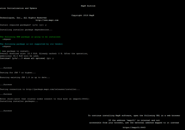
![]() For examples of options you can use with mapr-setup.sh, see Using mapr-setup.sh.
For examples of options you can use with mapr-setup.sh, see Using mapr-setup.sh.
5. Open the MapR Installer URL to start MapR installer: https://<Installer Node hostname/IPaddress>:9443
6. Enter credentials to login in to the MapR installer.

![]() You will be prompted to log in as the MapR Administrator user that you configured while running the mapr-setup.sh script.
You will be prompted to log in as the MapR Administrator user that you configured while running the mapr-setup.sh script.
Other Tasks You Can Perform with the MapR Installer
Once the initial installation completes, you can use the same MapR Installer URL to upgrade the cluster, apply a patch, or add nodes and additional services:
| Use this option . . . |
To |
| Extend Cluster |
Add a host to an existing cluster. |
| Incremental Install |
Add or upgrade services that are already installed on the cluster. |
| Maintenance Update |
Update your cluster to a new patch version of MapR Core or apply a patch. |
| Version Upgrade |
Upgrade the cluster to a newer MapR version, apply a patch, and upgrade services that are already installed on the cluster. |
| Shutdown |
Stop MapR services on the cluster. |
| Uninstall |
Remove existing MapR software before proceeding with a new installation. |
![]() The MapR Installer definitions are updated frequently. See Updating the MapR Installer to get the latest ecosystem components and MapR versions.
The MapR Installer definitions are updated frequently. See Updating the MapR Installer to get the latest ecosystem components and MapR versions.
7. With a successful login, you will be presented with following page. Click Next to continue with MapR installer.
8. Select MapR version, Add License After Installation Completes, Select Configuration Options, Select Services,
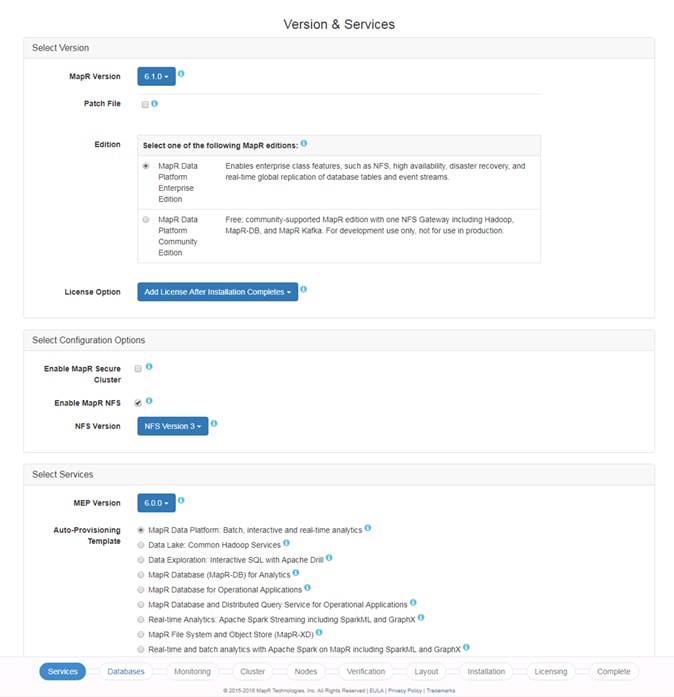
9. By default, service options as below are installed, click Show advanced server options to edit.
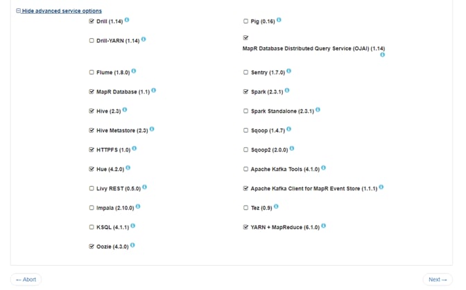
10. On the Database Setup page, select Database Type (Install Shared MySQL server in our case) and credentials. Click Next.
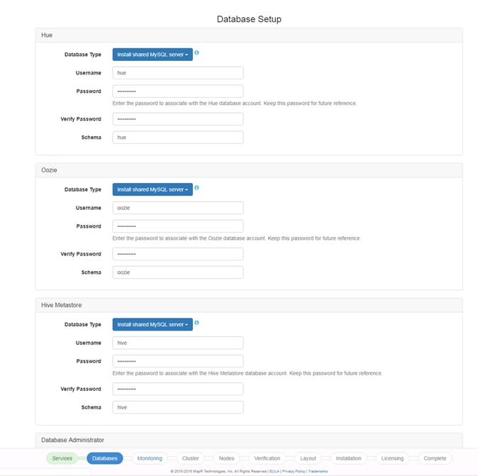
11. Install monitoring and logs services.
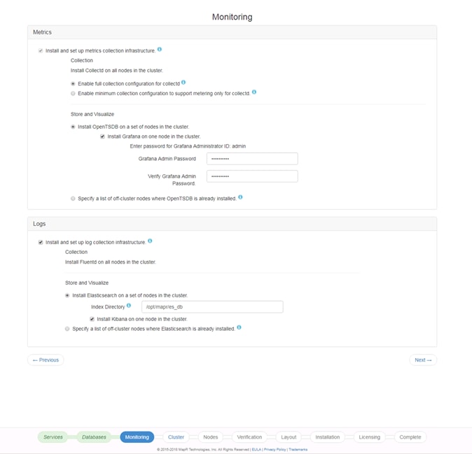
12. On the Set Up the Cluster page, enter the password for mapr user and cluster name for the cluster configuration.
This step creates the mapr user on each node part of the cluster.
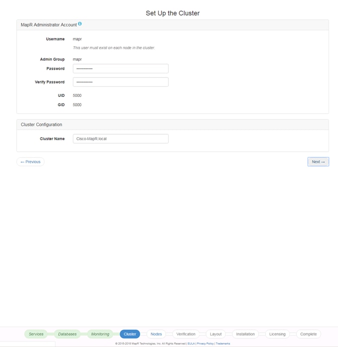
13. On the Node Configuration page, specify list of nodes, Configure Disks to be configured as part of the MapR cluster, Remote Authentication.
Generate SSH Keys
To generate the SSH keys, follow these steps:
1. To generate a key with default parameters (RSA, 2048 bits), enter the command ssh-keygen.
2. Accept the default location to store the key (~/.ssh/id_rsa) be pressing Enter (strongly recommended) or enter an alternative location.
3. Enter a passphrase consisting of 10 to 30 characters. The same rules as for creating safe passwords apply. It is strongly advised to refrain from specifying no passphrase.
![]() IMPORTANT! You should make absolutely sure that the private key is not accessible by anyone other than yourself (always set its permissions to 0600). The private key must never fall into the hands of another person.
IMPORTANT! You should make absolutely sure that the private key is not accessible by anyone other than yourself (always set its permissions to 0600). The private key must never fall into the hands of another person.
4. In order to change the password of an existing key pair, use the command ssh-keygen -p.
Copy an SSH Key
To copy a public SSH key to ~/.ssh/authorized_keys of a user on a remote machine, use the command ssh-copy-id. In order to copy your personal key stored under ~/.ssh/id_rsa.pub you may use the short form. In order to copy DSA keys or keys of other users, you need to specify the path as follows:
# ~/.ssh/id_rsa.pub
ssh-copy-id -i root@mapr01
# ~/.ssh/id_dsa.pub
ssh-copy-id -i ~/.ssh/id_dsa.pub root@mapr01
# ~notme/.ssh/id_rsa.pub
ssh-copy-id -i ~/.ssh/id_rsa.pub root@mapr01
1. In order to successfully copy the key, you need to enter the remote user's password. To remove an existing key, manually edit~/.ssh/authorized_keys.
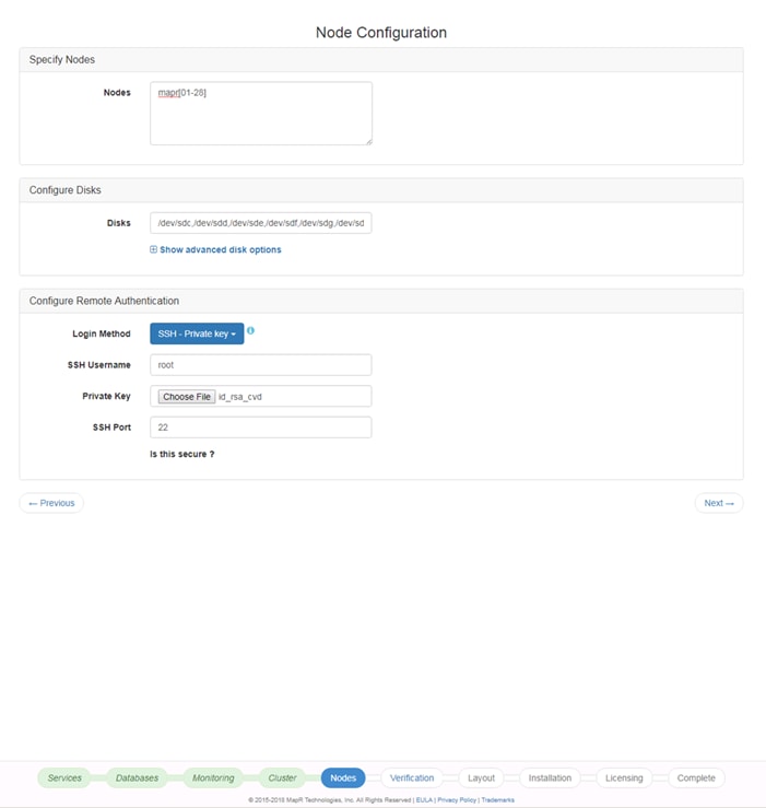
![]() MapR allows you to choose the appropriate disks for each node. Some nodes might have OS on /dev/sda and some other drives on other nodes, so the choice of disks are specific to the node. Choose non OS drives for the data drives.
MapR allows you to choose the appropriate disks for each node. Some nodes might have OS on /dev/sda and some other drives on other nodes, so the choice of disks are specific to the node. Choose non OS drives for the data drives.
2. MapR installer verifies nodes part of the installation. Nodes might report a warning message. Click OK to move forward with the installation. Click an Individual node to view logs.
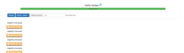
3. On Configure Service Layout page, review services to be installed. Click Install.
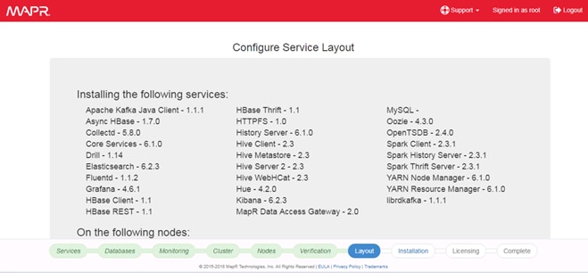
![]() Master services such as CLDB, resourceManager needs to be in two or more nodes to be in HA.
Master services such as CLDB, resourceManager needs to be in two or more nodes to be in HA.
4. Monitor the status of the installation progress. With a successful completion of the installation, click Next to assign license.
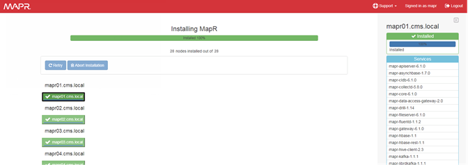
5. On the Licensing page, click Next.
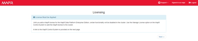
6. Review the completion page for the details about the services location.

7. Services installed on the nodes are highlighted in the screenshot below. On the same page there are buttons to perform various other option such as Extend Cluster or Incremental Install.
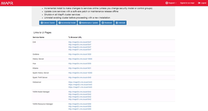
8. Click the link to access MapR Control System. Log in with the mapr username and password.
9. Click Admin > Cluster Settings > Licenses.
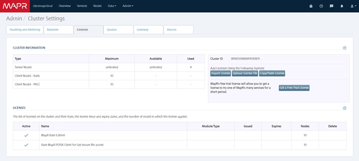
10. Choose an option to add licenses using one of the methods shown in the screenshot (above). We selected “Upload License File.”
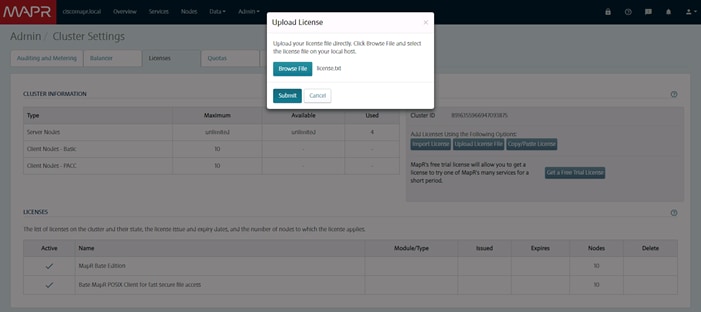
![]() Certain HA features of the MapR cluster will not start properly until a valid license is installed. When the trial license or a permanent one provided by MapR is successfully installed, restart the distributed CLDB services, as well as the ResourceManager service and the NFS service. This can be done from MapR Control System.
Certain HA features of the MapR cluster will not start properly until a valid license is installed. When the trial license or a permanent one provided by MapR is successfully installed, restart the distributed CLDB services, as well as the ResourceManager service and the NFS service. This can be done from MapR Control System.
Install Additional Hadoop Components
The final step in installing a MapR cluster is to install and bring up Hadoop ecosystem components, such as the following, and integrating them with a MapR cluster.
Please refer to the MapR Install guide at http://doc.mapr.com/display/MapR/Ecosystem+Guide for detailed instructions about installing and configuring Hadoop components:
· Apache Drill - Installing and using Drill on a MapR cluster
· Flume- Installing and using Flume on a MapR cluster
· Hive- Installing and using Hive on a MapR cluster, and setting up a MySQL metastore
· Hue - Installing and using Hue on MapR
· Oozie- Installing and using Oozie on a MapR cluster
· Pig- Installing and using Pig on a MapR cluster
· Spark- Installing and running Spark on MapR
· Sqoop- Installing and using Sqoop on a MapR cluster
Troubleshooting
This section includes some common troubleshooting questions and answers:
· Difficulty bringing up the cluster can be daunting, but most cluster problems are easily resolved. For the latest support tips, see http://answers.mapr.com.
· Can each node connect with the others? For a list of ports that must be open, see http://answers.mapr.com.
· Is the warden running on each node? On the node, run the following command as root:
$ service mapr-warden status
WARDEN running as process 18732
· If the warden service is not running, check the warden log file, /opt/mapr/logs/warden.log, for clues.
· To restart the warden service run:
$ service mapr-warden start
· The ZooKeeper service is not running on one or more nodes:
- Check the warden log file for errors related to resources, such as low memory
- Check the warden log file for errors related to user permissions
- Check for DNS and other connectivity issues between ZooKeeper nodes
· The MapR CLI program /opt/mapr/bin/maprcli won't run:
- Did you configure this node? See Install MapR Software.
- Permission errors appear in the log
Make sure that MapR's changes to the following files have not been overwritten by automated configuration management tools:
| /etc/sudoers |
Allows the mapr user to invoke commands as root |
| /etc/security/limits.conf
|
Allows MapR services to increase limits on resources such as memory, file handles, threads and processes, and maximum priority level |
| /etc/udev/rules.d/99-mapr-disk.rules |
Covers permissions and ownership of raw disk devices. |
![]() Before contacting Support, collect cluster's logs using the mapr-support-collect script.
Before contacting Support, collect cluster's logs using the mapr-support-collect script.
The Cisco UCS Integrated Infrastructure for Big Data and Analytics with MapR Data Platform enables the next-generation of big data architecture by providing simplified and centralized management, industry-leading performance, and a linearly scaling infrastructure and software platform.
The MapR Data Platform allows enterprises to build reliable, real-time applications by providing: a single cluster for streams, file storage database and analytics, persistence of streaming data, providing direct access to batch and interactive frameworks, a unified security framework for data-in-motion and data-at-rest with authentication, authorization and encryption, and a utility-grade reliability with self-healing and no single point-of-failure architecture.
The configuration detailed in this document can be extended to clusters of various sizes depending on application demands. Up to 28 servers can be supported with no additional switching in a single Cisco UCS domain with no network over-subscription. Scaling beyond 28 rack servers can be implemented by interconnecting multiple Cisco UCS domains using Nexus 9000 Series switches, scalable to thousands of servers and to hundreds of petabytes of storage, and managed from a single pane using Cisco UCS Central.
This section provides the BOM for the 28 Nodes Hadoop Base Rack and 8 Nodes Hadoop Expansion Rack. See Table 11 for the BOM for the Hadoop Base rack, Table 12 for the BOM for Hadoop Expansion Rack, Table 13 for the SUSE Linux Enterprise Server, and Table 14 lists MAPR SKUs available from Cisco.
Table 11 Bill of Materials for Cisco UCS C240 M5SX Hadoop Nodes Base Rack
| Part Number |
Description |
Qty |
| UCS-SP-C240M5-A2 |
SP C240 M5SX w/2x6132,6x32GB mem,VIC1387 |
28 |
| CON-OSP-C240M5A2 |
SNTC 24X7X4OS UCS C240 M5 A2 |
28 |
| UCS-CPU-6132 |
2.6 GHz 6132/140W 14C/19.25MB Cache/DDR4 2666MHz |
56 |
| UCS-MR-X32G2RS-H |
32GB DDR4-2666-MHz RDIMM/PC4-21300/dual rank/x4/1.2v |
168 |
| UCSC-PCI-1-C240M5 |
Riser 1 including 3 PCIe slots (x8, x16, x8); slot 3 required CPU2 |
28 |
| UCSC-MLOM-C40Q-03 |
Cisco VIC 1387 Dual Port 40Gb QSFP CNA MLOM |
28 |
| UCSC-PSU1-1600W |
Cisco UCS 1600W AC Power Supply for Rack Server |
56 |
| CAB-9K12A-NA |
Power Cord, 125VAC 13A NEMA 5-15 Plug, North America |
56 |
| UCSC-RAILB-M4 |
Ball Bearing Rail Kit for C220 & C240 M4 & M5 rack servers |
28 |
| CIMC-LATEST |
IMC SW (Recommended) latest release for C-Series Servers. |
28 |
| UCSC-HS-C240M5 |
Heat sink for UCS C240 M5 rack servers 150W CPUs & below |
56 |
| UCSC-BBLKD-S2 |
UCS C-Series M5 SFF drive blanking panel |
728 |
| UCSC-PCIF-240M5 |
C240 M5 PCIe Riser Blanking Panel |
28 |
| CBL-SC-MR12GM5P |
Super Cap cable for UCSC-RAID-M5HD |
28 |
| UCSC-SCAP-M5 |
Super Cap for UCSC-RAID-M5, UCSC-MRAID1GB-KIT |
28 |
| UCSC-RAID-M5HD |
Cisco 12G Modular RAID controller with 4GB cache |
28 |
| UCS-SP-FI6332-2X |
UCS SP Select 2 x 6332 FI |
1 |
| UCS-SP-FI6332 |
(Not sold standalone) UCS 6332 1RU FI/12 QSFP+ |
2 |
| CON-OSP-SPFI6332 |
ONSITE 24X7X4 (Not sold standalone) UCS 6332 1RU FI/No PSU/3 |
2 |
| UCS-PSU-6332-AC |
UCS 6332 Power Supply/100-240VAC |
8 |
| CAB-9K12A-NA |
Power Cord, 125VAC 13A NEMA 5-15 Plug, North America |
4 |
| QSFP-H40G-CU3M |
40GBASE-CR4 QSFP Direct-Attach Copper Cables |
56 |
| QSFP-40G-SR-BD |
QSFP40G BiDi Short-reach Transceiver |
8 |
| N10-MGT015 |
UCS Manager v4.0(1) |
2 |
| UCS-ACC-6332 |
UCS 6332 Chassis Accessory Kit |
2 |
| UCS-FAN-6332 |
UCS 6332 Fan Module |
8 |
| UCS-SP-H1P8TB-4X |
UCS SP 1.8 TB 12G SAS 10K RPM SFF HDD (4K) 4 Pack |
112 |
| UCS-SP-H1P8TB |
1.8 TB 12G SAS 10K RPM SFF HDD (4K) |
448 |
| UCS-SP-HD-1P8T-2 |
1.8TB 12G SAS 10K RPM SFF HDD (4K) 2 Pack |
28 |
| UCS-SP-HD-1P8T |
SP 1.8TB 12G SAS 10K RPM SFF HDD (4K) |
56 |
Table 12 Bill of Materials for Hadoop Nodes Expansion Rack
| Description |
Qty |
|
| UCS-SP-C240M5-A2 |
SP C240 M5SX w/2x6132,6x32GB mem, VIC1387 |
8 |
| CON-OSP-C240M5A2 |
SNTC 24X7X4OS UCS C240 M5 A2 |
8 |
| UCS-CPU-6132 |
2.6 GHz 6132/140W 14C/19.25MB Cache/DDR4 2666MHz |
16 |
| UCS-MR-X32G2RS-H |
32GB DDR4-2666-MHz RDIMM/PC4-21300/dual rank/x4/1.2v |
48 |
| UCSC-PCI-1-C240M5 |
Riser 1 including 3 PCIe slots (x8, x16, x8); slot 3 required CPU2 |
8 |
| UCSC-MLOM-C40Q-03 |
Cisco VIC 1387 Dual Port 40Gb QSFP CNA MLOM |
8 |
| UCSC-PSU1-1600W |
Cisco UCS 1600W AC Power Supply for Rack Server |
16 |
| CAB-9K12A-NA |
Power Cord, 125VAC 13A NEMA 5-15 Plug, North America |
16 |
| UCSC-RAILB-M4 |
Ball Bearing Rail Kit for C220 & C240 M4 & M5 rack servers |
8 |
| CIMC-LATEST |
IMC SW (Recommended) latest release for C-Series Servers. |
8 |
| UCSC-HS-C240M5 |
Heat sink for UCS C240 M5 rack servers 150W CPUs and below |
16 |
| UCSC-BBLKD-S2 |
UCS C-Series M5 SFF drive blanking panel |
208 |
| UCSC-PCIF-240M5 |
C240 M5 PCIe Riser Blanking Panel |
8 |
| CBL-SC-MR12GM5P |
Super Cap cable for UCSC-RAID-M5HD |
8 |
| UCSC-SCAP-M5 |
Super Cap for UCSC-RAID-M5, UCSC-MRAID1GB-KIT |
8 |
| UCSC-RAID-M5HD |
Cisco 12G Modular RAID controller with 4GB cache |
8 |
| UCS-SP-H1P8TB-4X |
UCS SP 1.8 TB 12G SAS 10K RPM SFF HDD (4K) 4Pk |
48 |
| UCS-SP-H1P8TB |
1.8 TB 12G SAS 10K RPM SFF HDD (4K) |
192 |
| UCS-SP-HD-1P8T-2 |
1.8TB 12G SAS 10K RPM SFF HDD (4K) 2 Pack |
8 |
| UCS-SP-HD-1P8T |
SP 1.8TB 12G SAS 10K RPM SFF HDD (4K) |
16 |
Table 13 SUSE Enterprise Linux Subscription(s)
| SUSE Enterprise Linux Server |
||
| SLES-2S2V-3A |
SUSE Enterprise Linux Server |
28 |
| CON-ISV1-EL2S2V3A |
3-year Support for SUSE Enterprise Linux Server |
28 |
Table 14 MAPR SKU’s Available at Cisco
| Cisco TOP SKU |
Cisco PID with Duration |
Product Name |
| UCS-BD-MR-ES= |
UCS-BD-MR-ES-3Y |
MapR Enterprise Standard License; Support - 3 Year |
| UCS-BD-MR-EP= |
UCS-BD-MR-EP-3Y |
MapR Enterprise Premier License; Support - 3 Year |
| UCS-BD-MD-SL= |
UCS-BD-MD-SL-3Y |
Apache Drill support on MapR Cluster, Subscription License |
| UCS-BD-MH-SL= |
UCS-BD-MH-SL -3Y |
Apache HBase MapR support, Subscription License |
| UCS-BD-MI-SL= |
UCS-BD-MI-SL-3Y |
Impala Query Engine support on MapR Cluster, Subscription License |
| UCS-BD-MK-SL= |
UCS-BD-MK-SL-3Y |
Apache Spark MapR support, Subscription License |
| UCS-BD-MAS-AR= |
UCS-BD-MAS-AR-3Y |
Add-On 24/7 support for MapR Spark; Renewal. |
| UCS-BD-MPRMCP-B= |
UCS-BD-MPRMCP-B-3Y |
Premium Subscription License for MapR Enterprise Edition |
Hardik Patel, Solutions Architect, Computing Systems Product Group, Cisco Systems, Inc.
Hardik Patel is Solution Architect with the Computing Systems Product Group. His focus includes Big Data and analytics system, next generation data center architecture and performance.
Acknowledgements
The author would like to thank the following for their support and contribution to the design, creation, and validation of this Cisco Validated Design:
· Karthik Kulkarni, Architect, Computing Systems Product Group, Cisco Systems, Inc.
· MapR Team – Greg Reeves, Andy Learner, Antje Barth
· SUSE Team – Bryan Gartner
 Feedback