- Preface
- Using the Cisco TelePresence System Administration
- Device Information
- Configuring the Cisco TelePresence System
- Troubleshooting the CTS 500
- Troubleshooting the CTS 500-32 and CTS 500-37
- Troubleshooting the CTS 1000
- Troubleshooting the CTS 1100
- Troubleshooting the CTS 1300
- Troubleshooting the TX1300 47
- Troubleshooting the CTS 3000 and CTS 3200
- Troubleshooting the CTS 3010 and CTS 3210
- Monitoring the Cisco TelePresence System
- Satellite Licenses for the Cisco TelePresence System
- Glossary
- Index
Cisco TelePresence System Adminstration Guide
Bias-Free Language
The documentation set for this product strives to use bias-free language. For the purposes of this documentation set, bias-free is defined as language that does not imply discrimination based on age, disability, gender, racial identity, ethnic identity, sexual orientation, socioeconomic status, and intersectionality. Exceptions may be present in the documentation due to language that is hardcoded in the user interfaces of the product software, language used based on RFP documentation, or language that is used by a referenced third-party product. Learn more about how Cisco is using Inclusive Language.
- Updated:
- February 16, 2012
Chapter: Device Information
Device Information
Contents
This chapter contains the following sections:
•![]() Accessing the Device Information Window
Accessing the Device Information Window
•![]() System Information and Status Tabs
System Information and Status Tabs
Accessing the Device Information Window
The Device Information window is the first thing you see when you log on to the Cisco TelePresence System Administration interface. It is from this window that you can access configuration, troubleshooting, and monitoring tasks for the Cisco TelePresence System (CTS) as well as view information about the devices installed on your system.
Before You Begin
To access the Cisco TelePresence System Administration interface for the first time, complete the steps in Logging into the Cisco Unified CM Administrator section of Cisco Unified Communications Manager Configuration Guide for the Cisco TelePresence System.
To view information about the Cisco TelePresence devices on your system:
Step 1 ![]() Log in to the Cisco TelePresence System Administration interface by completing the following steps:
Log in to the Cisco TelePresence System Administration interface by completing the following steps:
a. ![]() Open an Internet Explorer browser window and type in the IP address of the system in the URL field and click Enter. The Cisco TelePresence Administration Login Screen appears, as shown in Figure 2-1.
Open an Internet Explorer browser window and type in the IP address of the system in the URL field and click Enter. The Cisco TelePresence Administration Login Screen appears, as shown in Figure 2-1.

Note ![]() If you need to obtain the IP address, do the following:
If you need to obtain the IP address, do the following:
1. ![]() On the IP phone, locate "Manual" at the bottom of the screen and press the Manual soft key.
On the IP phone, locate "Manual" at the bottom of the screen and press the Manual soft key.
Or
2. ![]() Locate "Info" at the bottom of the screen and press the Info soft key.
Locate "Info" at the bottom of the screen and press the Info soft key.
3. ![]() Scroll down to the IP Address listing and copy the address.
Scroll down to the IP Address listing and copy the address.
Figure 2-1 Cisco TelePresence System Administration Login Screen
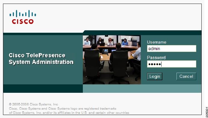
b. ![]() In the Admin field, type admin.
In the Admin field, type admin.
c. ![]() In the Password field, type cisco.
In the Password field, type cisco.
Note ![]() You can change the default password in Unified CM. See the Cisco Unified Communications Manager Configuration Guide for the Cisco TelePresence System.
You can change the default password in Unified CM. See the Cisco Unified Communications Manager Configuration Guide for the Cisco TelePresence System.
d. ![]() Click Login.
Click Login.
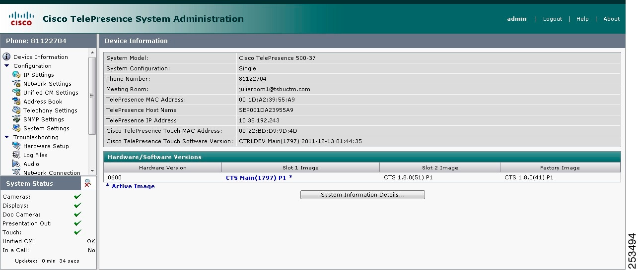
The Device Information window appears, as shown in Figure 2-2.
Figure 2-2 Device Information Screen
Step 2 ![]() View the information in the following sections within the Device Information window:
View the information in the following sections within the Device Information window:
•![]() System Information and Status Tabs
System Information and Status Tabs
Device Information Fields
The Device Information area contains details about the settings that were configured in the CTS and the Unified CM. The information in Table 2-1 describes setting descriptions in the Device Information fields.
Note ![]() The Cisco TelePresence System device type must be specifically selected before you can upgrade to CTS Software Release 1.8.0 and later releases.
The Cisco TelePresence System device type must be specifically selected before you can upgrade to CTS Software Release 1.8.0 and later releases.
|
|
|
|---|---|
System Model |
Cisco TelePresence System model can be one of the following: • • • • • • • • • • • |
System Configuration |
Indicates the number of high-definition displays for this system. |
Phone Number |
Call pattern for the IP phone as defined in Unified CM. |
Meeting Room |
Name of the meeting room in which this particular CTS is located as defined in Unified CM. |
TelePresence MAC Address |
MAC address of the primary CTS codec. |
TelePresence Host Name |
Host name of the primary CTS codec. |
TelePresence IP Address |
IP address of the primary CTS codec. |
Cisco TelePresence Touch MAC Address |
MAC address of the Cisco TelePresence Touch 12, if your system uses the touch device instead of the Cisco Unified IP phone for call control. |
Cisco TelePresence Touch Software Version |
Software version used by the Cisco TelePresence Touch 12, if your system uses the touch device instead of the Cisco Unified IP phone for call control. |
IP Phone MAC Address |
MAC Address of the IP phone as entered in Unified CM. |
IP Phone Host Name |
Host name of the IP phone as configured in Unified CM. |
IP Phone IP Address |
IP address of the IP phone as configured in Unified CM. |
IP Phone Software Version |
Version of the operating system software installed on this IP phone. |
Hardware/Software Versions
Version information is collected from the hardware and software versions currently loaded in the system. In the Hardware/Software Versions area, data in bold blue text (with an asterisk "*") indicates which software image is currently running. Table 2-2 describes the hardware and software versions information fields.
System Information and Status Tabs
Information provided in the System Information Details window is used by Cisco technical support personnel to assist in troubleshooting your system.
To obtain a detailed report about the system:
Step 1 ![]() Log in to the Cisco TelePresence System Administration page. The Device Information window appears.
Log in to the Cisco TelePresence System Administration page. The Device Information window appears.
Step 2 ![]() Click on the System Information Details bar. A new window opens.
Click on the System Information Details bar. A new window opens.
Step 3 ![]() Click the following tabs in the new window:
Click the following tabs in the new window:
Step 4 ![]() Click Close to close the window.
Click Close to close the window.
System Information Details
Detailed system information is displayed per codec:
•![]() One codec—For systems with one codec, all information displayed is for the system's single codec.
One codec—For systems with one codec, all information displayed is for the system's single codec.
•![]() Three codecs—For systems with three codecs, hardware and software information is displayed for left, center, and right codecs.
Three codecs—For systems with three codecs, hardware and software information is displayed for left, center, and right codecs.
•![]() Presentation codec—For systems that include a presentation codec, hardware and software information for the presentation codec is also displayed.
Presentation codec—For systems that include a presentation codec, hardware and software information for the presentation codec is also displayed.
Table 2-3 describes the fields found in the System Information Details window.
|
|
|
|---|---|
UDI_Hardware_Ver |
Unique device identifier hardware version number. |
UDI_Serial |
Unique device identifier serial number. |
UDI_PID |
Unique device identifier product identification number. |
System_Up_Time |
Amount of time the system has been running since last reboot. |
OS_Ver |
Version number of the operating system. |
OS_BuildTime |
Time at which operating system was built. |
UBOOT_Ver |
Version number of the application that controls the boot process. |
CF_Model |
Compact flash model number. |
Camera_PID |
Camera product identification number.1 |
Camera_Hardware |
Camera hardware number.1 |
Camera_Firmware_Ver |
Camera firmware version number.1 |
Camera_Hardware_Ver |
Camera hardware version number.1 |
Camera_BuildTime |
Time at which the camera firmware version was built.1 |
Document_Camera_Serial |
Document camera serial number.2 |
Document_Camera_Hardware_Ver |
Document camera hardware version number.2 |
Document_Camera_Model |
Document camera model number.2 |
Display_Serial |
Serial number of the display. |
Display_Hardware_Ver |
Display hardware version number. |
Display_Model |
Display model number. |
Display_BootCode_Ver |
Version number of the boot loader for AppCode. BootCode also provides upgrade feature for AppCode. |
Display_AppCode_Ver |
Version number for AppCode. AppCode provides monitoring, managing control, and diagnostic functionality. |
FPGA_ID |
Field programmable gate array identification number. |
FPGA_Rev |
Field programmable gate array revision number. |
FPGA_BuildTime |
Time at which field programmable gate array was built. |
MainRx_DevID |
Main camera device identification number. |
MainRx_Rev |
Main camera revision number. |
AuxRx_DevID |
Auxiliary camera (document camera or VGA input device) device identification number. |
AuxRx_Rev |
Auxiliary camera (document camera or VGA input device) revision number. |
MainTx_DevID |
Main display (plasma) device identification number. |
MainTx_Rev |
Main display (plasma) revision number. |
AuxTx_DevID |
Auxiliary display (projector) device identification number. |
AuxTx_Rev |
Auxiliary display (projector) revision number. |
OSD_DEVICE1_BuildTime |
On screen display (device 1) build time. |
OSD_DEVICE5_BuildTime |
On screen display (device 5) build time. |
VCODEC_encoder_Card_Ver |
Video CODEC encoder card version number. |
VCODEC_decoder_Card_Ver |
Video CODEC decoder card version number. |
Audio_Hardware_Ver |
Audio version hardware version number. |
Audio_CPLD_Ver |
Audio complex programmable logic device version number. |
Audio_DSP_BuildID |
Audio DSP software version.3 |
Audio_Base_BoardID |
Type of audio base board. Choices are: • • |
Audio_Base_Board_FAB_Ver |
Hardware version of the audio (base) board |
Audio_Base_Board_FW_Ver |
Firmware version of the audio (base) board |
Audio_Extension_UnitID |
Type of audio extension board. The board type is either 0xAE or is disconnected. |
Audio_Extension_Unit_FAB_Ver |
Hardware version of the audio extension board. |
Audio_Extension_Unit_FW_Ver |
Firmware version on the audio extension board. |
Audio_Clock_Source |
Clock source syncing the audio and video streams. |
Audio_PCB_S/N |
CTS 500 Series and CTS 1300 only. Unique device identification (UDI) containing serial numbers unique to that printed circuit board (PCB). |
Audio_PCB_P/N |
CTS 500 Series and CTS 1300 only. Unique device UDI containing part numbers unique to that PCB. |
Audio_PCB_Rev |
CTS 500 Series and CTS 1300 only. Unique UDI containing hardware revision information unique to that PCB. |
PoE_Reset_Available |
Indicates whether Power over Ethernet (PoE) Reset feature is available. |
Mfg_Installed_Cert |
Security certificate for encryption defined by Cisco Root Certificate Authority. |
Locally_Significant_Cert |
Security certificate obtained through Certificate Authority Proxy Function (CAPF), which supersedes the manufacturing installed security certificate. |
Max_Security_Setting |
Configured security setting. |
Aux Control Unit_Model |
Auxiliary control unit model. |
Aux Control Unit_Ver |
Auxiliary control unit system firmware version. |
Aux Control Unit_UDI_Vid |
Auxiliary control unit unique device identifier version identification. |
Aux Control Unit_UDI_Pid |
Auxiliary control unit unique device identifier product identification number. |
Aux Control Unit_UDI_Sn |
Auxiliary control unit unique device identifier serial number |
Projector_Model |
Projector model number, if projector is installed. |
Presentation Display Model |
Presentation display information. |
Phone_midlet_status |
Displays MIDlet status. |
Phone_midlet_version |
Displays MIDlet version |
1 CTS 1300 displays information for Center, Left, and Right cameras. 2 The document camera is not available on the CTS 1300. 3 CTS devices are backward compatible up to two CTS Software Releases. Cisco recommends that you upgrade to the latest version software. |
Status Details
Detailed status information is displayed per codec:
•![]() One codec—For systems with one codec, all information displayed is for the system's single codec.
One codec—For systems with one codec, all information displayed is for the system's single codec.
•![]() Three codecs—For systems with three codecs, hardware and software information is displayed for left, center, and right codecs.
Three codecs—For systems with three codecs, hardware and software information is displayed for left, center, and right codecs.
•![]() Presentation codec—For systems that include a presentation codec, hardware and software information for the presentation codec is also displayed.
Presentation codec—For systems that include a presentation codec, hardware and software information for the presentation codec is also displayed.

Tip ![]() You can also view this window by returning to the Device Information window and clicking the magnifying glass icon in the upper right corner of the Status pane, which is in the lower left corner of the screen. See Figure 2-3 for an example of the magnifying glass icon and the Status pane.
You can also view this window by returning to the Device Information window and clicking the magnifying glass icon in the upper right corner of the Status pane, which is in the lower left corner of the screen. See Figure 2-3 for an example of the magnifying glass icon and the Status pane.
Figure 2-3 CTS System Status
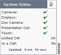
Table 2-4 contains descriptions of the Status Details fields. CTS displays a red X next to devices that are not operational or in error.
|
|
|
|---|---|
|
|
• • Note • • Note – – – • • • • Note • • • • • • • • • |
System Status |
• • • • • • |
Note |
|
Time Since Last Update
A running timer is located at the bottom of the Status Details page that displays elapsed time since last update.
Microphone Status
A roadmap of microphone status information icons is displayed at the bottom of the Status Details page.
|
• |
|
• |
|
• |
|
• |
Note ![]() To determine individual microphone and speaker functionality, use the hardware troubleshooting interface for your system. See Where to Go Next to locate the troubleshooting support document for your Cisco TelePresence system.
To determine individual microphone and speaker functionality, use the hardware troubleshooting interface for your system. See Where to Go Next to locate the troubleshooting support document for your Cisco TelePresence system.
Where to Go Next
Proceed to the following Cisco TelePresence system administration tasks from the Device Information window:
Configure
•![]() Configuring the Cisco TelePresence System
Configuring the Cisco TelePresence System
Troubleshoot
Platform-specific troubleshooting:
•![]() Troubleshooting the CTS 500-32 and CTS 500-37
Troubleshooting the CTS 500-32 and CTS 500-37
•![]() Troubleshooting the CTS 1300-65
Troubleshooting the CTS 1300-65
•![]() Troubleshooting the CTS 3000 and CTS 3200
Troubleshooting the CTS 3000 and CTS 3200
•![]() Troubleshooting the CTS 3010 and CTS 3210
Troubleshooting the CTS 3010 and CTS 3210
Monitor
 Feedback