Switch Operating Procedure
Available Languages
Table Of Contents
Managing the Configuration Files
Restoring a Saved Configuration
Enabling and Disabling ILMI on a Port
Displaying the ILMI Port Configuration
Displaying and Clearing ILMI Management Statistics
Determining the Software Version Number from Filenames
Displaying Software Revisions in Use
Displaying Software Revisions for All Cards
Displaying Software Revisions for a Single Card
Switching Between Redundant PXM Cards
Switching Between Redundant AXSM Cards
Removing Redundancy between Two Cards
Displaying APS Line Information
Removing APS Redundancy between Two Lines
Managing Network Clock Sources
Viewing the Configured Clock Sources
Restoring a Clock Source After Failure
Managing Service Class Templates (SCTs)
Displaying the SCT Assigned to a Port
Displaying the SCT Assigned to a Card
Port SCT Bandwidth and Policing Parameters (bw)
Port SCT General Parameters (gen)
Port SCT COSB Parameters (cosb)
Port SCT Virtual Circuit Threshold Parameters (vcThr)
Port SCT COSB Threshold Parameters (cosThr)
Card SCT Bandwidth and Policing Parameters (bw)
Card SCT General SCT Parameters (gen)
Card SCT COSB Parameters (cosb)
Card SCT Virtual Circuit Threshold Parameters (vcThr)
Card SCT COSB Threshold Parameters (cosThr)
Viewing an ATM Port Configuration
Displaying a Resource Partition Configuration
Changing a Resource Partition Configuration
Configuring VPI and VCI Ranges for SVCs and SPVCs
Displaying Load Sharing Status
Starting and Managing Telnet Sessions to Other Switches
Returning to a Previous Session
Returning to the Original CLI Session
Switch Operating Procedures
This chapter describes procedures you can use to manage the MGX 8850 switch.
Managing the Configuration Files
The following sections describe how to save a switch configuration in a single zipped file, clear or erase a configuration, and restore a configuration from a file.
Saving a Configuration
After configuring your switch or after making configuration updates, it is wise to save the configuration. Restoring a saved configuration is much easier than reentering all the commands used to configure the switch.
To save a configuration, you use the saveallcnf command, which saves the configuration to a file in the C:/CNF directory. The file is named using the switch name and the current date as follows:
Name_01_DateTime.zip.
The date appears in YYYYMMDD (year, month, day) format, and the time appears in HHMM (hour, minute) format. For example, if the configuration for a switch named "mgx8850a" were saved on February 29th, 2000 at 2:31pm, the file would be named C:/CNF/mgx8850a_01_200002291431.zip.
You can save a configuration if both of the following are true:
•
No save or restore process is currently running.
•

Caution
To save a switch configuration, use the following procedure.
Step 1
Step 2
mgx8850a.7.PXM.a > saveallcnfStep 3
When the save is complete, the switch prompt reappears, and the new file is stored in the C:/CNF directory. The switch displays the saved filename as shown below:
pop20one.7.PXM.a > saveallcnfThe 'saveallcnf' command can be time-consuming. The shelfmust not provision new circuits while this command is running.Do not run this command unless the shelf configuration is stableor you risk corrupting the saved configuration file.Do you want to proceed (Yes/No)? ysaveallcnf: shelf configuration saved in C:/CNF/pop20one_01_200006151550.zip.
Note
Clearing a Configuration
There are two commands that allow you to clear the switch configuration: clrcnf and clrallcnf.
To clear switch provisioning data such as the PNNI controller, AXSM ports, and SPVC connections, enter the clrcnf command. This command clears all configuration data except the following:
•
•
•
•
•
To clear the entire configuration, use the clrallcnf command. This command clears all the provisioning data and most of the general switch configuration parameters such as the switch name and SNMP configuration. The clrallcnf command clears all IP addresses except the boot IP address.
Restoring a Saved Configuration
You can restore a configuration if all of the following are true:
•
•
•
Caution
To restore a saved switch configuration, use the following procedure.
Step 1
Step 2
Note

Tips
Step 3
mgx8850a.7.PXM.a > restoreallcnf -f filename
Caution
Replace filename with the name of the saved configuration file.You do not have to enter the path to the file or the extension. For information on the location and name of the file, see "Saving a Configuration."
Managing ILMI
The following sections describe how to:
•
•
•
•
Enabling and Disabling ILMI on a Port
The MGX 8850 switch provides several commands that you can use to enable or disable ILMI on a port. For instructions on enabling or disabling ILMI from an AXSM card prompt, refer to "Configuring ILMI on a Port," in "Provisioning AXSM Communication Links." To enable or disable ILMI from the PXM45 prompt, use the following procedure.
Step 1
Step 2
To enable or disable ILMI on a port, enter the cnfilmienable command as follows:
popeye2.1.7pxm.a>cnfilmienable <portid> <no | yes>Replace portid using the format slot:bay.line:ifNum. Table 6-1 describes these parameters.
Enter yes to enable ILMI on the port, or enter no to disable ILMI.
Step 3
Displaying the ILMI Port Configuration
The following procedure describes some commands you can use to view the ILMI port configuration.
Step 1
Step 2
pop20two.1.AXSM.a > dspilmisSig. rsrc Ilmi Sig Sig Ilmi S:Keepalive T:conPoll K:conPollPort Part State Vpi Vci Trap Interval Interval InactiveFactor---- ---- ---- ---- ---- --- ------------ ---------- ----------1 1 Off 0 16 On 1 5 42 1 Off 0 16 On 1 5 43 1 Off 0 16 On 1 5 44 1 Off 0 16 On 1 5 4The example above shows that all ports are configured for the default ILMI values and that ILMI has not been started on any port. Table 6-2 describes each of the report columns.
Step 3
pop20one.10.AXSM.a > dspilmi <ifnum> <partitionId>Replace ifnum with the interface number of the port, and replace partitionID with the partition number assigned to the port. You can view both of these numbers in the dspilmis command report. The following is an example report for the dspilmi command. Table 6-2 describes each of the columns that appear in the command report.
pop20one.10.AXSM.a > dspilmi 1 1Sig. rsrc Ilmi Sig Sig Ilmi S:Keepalive T:conPoll K:conPollPort Part State Vpi Vci Trap Interval Interval InactiveFactor---- ---- ---- ---- ---- --- ------------ ---------- ----------1 1 On 0 16 On 1 5 4Step 4
pop20one.7.PXM.a > dsppnportsSummary of total connections(p2p=point to point,p2mp=point to multipoint,SpvcD=DAX spvc,SpvcR=Routed spvc)Type #Svcc: #Svpc: #SpvcD: #SpvpD: #SpvcR: #SpvpR: #Total:p2p: 0 0 0 0 0 0 0p2mp: 0 0 0 0 0 0 0Total=0Summary of total configured SPVC endpointsType #SpvcCfg: #SpvpCfg:p2p: 0 0p2mp: 0 0Per-port status summaryPortId IF status Admin status ILMI state #Conns7.35 up up Undefined 07.36 up up Undefined 07.37 up up Undefined 07.38 up up Undefined 0Type <CR> to continue, Q<CR> to stop:10:1.1:1 up up UpAndNormal 0The ILMI operational state is displayed as one of the following: Disable, EnableNotUp, or UpAndNormal. When ILMI is disabled on the port, the operational status is Disable. When ILMI is enabled on the local port but cannot communicate with ILMI on the remote port, the status is EnableNotUp (This happens when ILMI is disabled on the remote end.). When ILMI is enabled and communicating with ILMI on the remote port, the ILMI state is UpAndNormal.
Step 5
pop20one.7.PXM.a > dsppnilmi <portid>Replace portid using the format slot:bay.line:ifNum. Table 6-1 describes these parameters. The following example shows the format of the dsppnilmi command report.
pop20one.7.PXM.a > dsppnilmi 10:1.1:1Port: 10:1.1:1 Port Type: PNNI Side: networkAutoconfig: disable UCSM: disableSecure Link Protocol: enableChange of Attachment Point Procedures: enableModification of Local Attributes Standard Procedure: enableAddressreg: Permit AllVPI: 0 VCI: 16Max Prefix: 16 Total Prefix: 0Max Address: 64 Total Address: 0Resync State: 0 Node Prefix: yesPeer Port Id: 16848897 System_Id : 0.80.84.171.226.192Peer Addressreg: enablePeer Ip Address : 0.0.0.0Peer Interface Name : atmVirtual.01.1.1.01ILMI Link State : UpAndNormalILMI Version : ilmi40INFO: No Prefix registered
Displaying and Clearing ILMI Management Statistics
The following procedure describes some commands you can use to view ILMI management statistics.
Step 1
pop20one.10.AXSM.a > dspilmicnt <ifnum> <partitionId>Replace ifnum with the interface number of the port, and replace partitionID with the partition number assigned to the port. You can view both of these numbers in the dspilmis command report. The following is an example report for the dspilmicnt command.
pop20one.10.AXSM.a > dspilmicnt 1 1If Number : 1Partition Id : 1SNMP Pdu Received : 36914GetRequest Received : 18467GetNext Request Received : 0SetRequest Received : 0Trap Received : 1GetResponse Received : 18446GetResponse Transmitted : 18467GetRequest Transmitted : 18446Trap Transmitted : 4Unknown Type Received : 0ASN1 Pdu Parse Error : 0No Such Name Error : 0Pdu Too Big Error : 0Step 2
pop20one.10.AXSM.a > clrilmicnt <ifnum> <partitionId>Replace ifnum with the interface number of the port, and replace partitionID with the partition number assigned to the port. The following example shows the switch response to this command.
pop20one.10.AXSM.a > clrilmicnt 1 1ilmi stats for ifNum 1, partId 1 clearedStep 3
Deleting ILMI Prefixes
The procedure for adding ILMI prefixes is described in "Configuring ILMI Dynamic Addressing" in "Provisioning AXSM Communication Links." The following procedure describes how to delete an ILMI address prefix from a port.
Step 1
Step 2
pop20one.7.PXM.a > dspprfx <portid>Replace portid with the port address using the format slot:bay.line:ifnum. These parameters are described in Table 6-1. For example:
pop20one.7.PXM.a > dspprfx 10:2.2:4INFO: No Prefix registeredIn the example above, no ILMI prefixes have been assigned to the port, so the port will use the prefix configured for the SPVC prefix.
Step 3
pop20one.7.PXM.a > dnpnport 10:2.2:4Step 4
popeye2.7.PXM.a > delprfx <portid> atm-prefixReplace portid using the format slot:bay.line:ifNum. Table 6-1 describes these parameters.
Replace atm-prefix with the 13-byte ATM address prefix in use.
Step 5
pop20one.7.PXM.a > uppnport 10:2.2:4Step 6
Determining the Software Version Number from Filenames
The following version management commands require a version number to be entered in a specific format:
•
•
•
•
•
•
In most cases, you will find the correct firmware version numbers in the 2.0.12 Version Software Release Notes, Cisco WAN MGX 8850 Software. If the release notes are not available, you can use the firmware filename to determine the version number as described below.
Step 1
Step 2
mgx8850a.7.PXM.a > cd C:/FW
Note
Step 3
mgx8850a.7.PXM.a > llThe display shows:
pop20one.7.PXM.a > llsize date time name-------- ------ ------ --------512 APR-19-2000 01:24:16 . <DIR>512 APR-19-2000 01:24:16 .. <DIR>2248536 MAY-17-2000 15:12:16 axsm_002.000.000.000.fw591008 MAY-15-2000 21:37:28 axsm_002.000.000.000_bt.fw839392 MAY-15-2000 21:37:36 pxm45_002.000.000.000_bt.fw3450888 MAY-15-2000 21:37:48 pxm45_002.000.000.000_mgx.fw2260984 JUN-06-2000 07:18:40 axsm_002.000.001.000.fw592288 JUN-06-2000 07:09:02 axsm_002.000.001.000_bt.fw844720 JUN-06-2000 07:09:26 pxm45_002.000.001.000_bt.fw3481816 JUN-06-2000 07:11:00 pxm45_002.000.001.000_mgx.fwIn the file system :total space : 819200 K bytesfree space : 786279 K bytesFigure 6-1 shows the information contained in filenames for released software.
Figure 6-1 Filename Format for Released Software
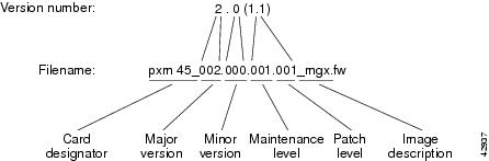
Filenames that include "_mgx" are for runtime PXM45 firmware, and filenames that include "_bt" are for boot firmware. AXSM runtime firmware images do not have an image description after the version number. When you first receive the switch from Cisco, there will be single versions of each file. If you download updates to any files, there will be multiple versions of those files.
Figure 6-2 shows the information contained in filenames for prereleased firmware. If you are evaluating nonreleased firmware, the filename format shows that the firmware is pre-released and indicates the development level of the prerelease firmware.
Figure 6-2 Filename Format for Prereleased Firmware

Step 4
Write the version number down in the format required by the revision management commands. The following example shows the required format. If you are logged in as a user with SERVICE_GP access privileges, you can display this example by entering any of the revision management commands without parameters.
pop20one.7.PXM.a > runrevERR: Syntax: runrev <slot> <revision>revision - revision number. E.g.,2.0(1)2.0(1.248)2.0(0)B1 or 2.0(0)B22.0(0)A1 or 2.0(0)A22.0(0)I1 or 2.0(0)I22.0(0)DThe first example above, 2.0(1), is for released firmware version 2.0, maintenance release 1. The second example, 2.0(1.248), is for patch 248 to version 2.0, maintenance release 1. The other examples are for prerelease firmware. Prerelease firmware does not include patches; the maintenance release number is increased for each software change.
Table 6-4 shows some example filenames and the correct version numbers to use with the revision management commands.
Displaying Software Revisions in Use
The following sections describe:
•
•
Displaying Software Revisions for All Cards
To display the boot and runtime software version in use on every card in the switch, enter the dsprevs command as shown in the following example:
pop20one.7.PXM.a > dsprevspop20one System Rev: 02.00 Jan. 24, 2001 18:32:57 PSTMGX8850 Node Alarm: NONEPhysical Logical Inserted Cur Sw Boot FWSlot Slot Card Revision Revision-------- ------- -------- -------- --------01 01 AXSM_4OC12 2.0(12) 2.0(12)02 02 AXSM_4OC12 2.0(12) 2.0(12)03 03 --- --- ---04 04 --- --- ---05 05 --- --- ---06 06 --- --- ---07 07 PXM45 2.0(12) 2.0(12)08 07 PXM45 2.0(12) 2.0(12)09 09 --- --- ---10 10 --- --- ---11 11 --- --- ---12 12 --- --- ---13 13 --- --- ---14 14 --- --- ---15 15 --- --- ---16 16 --- --- ---Type <CR> to continue, Q<CR> to stop:To display the upgrades status of the runtime software on all switch cards, enter the dsprevs -status command as shown in the following example:
pop20one.7.PXM.a > dsprevs -statuspop20one System Rev: 02.00 Jan. 24, 2001 18:37:16 PSTMGX8850 Node Alarm: NONEPhy. Log. Cur Sw Prim Sw Sec Sw Rev ChgSlot Slot Revision Revision Revision Status---- ---- -------- -------- -------- -------01 01 2.0(12) 2.0(12) 2.0(12) ---02 02 2.0(12) 2.0(12) 2.0(12) ---03 03 39.164(233.78) --- --- ---04 04 251.219(56.207) --- --- ---05 05 254.11(150.37) --- --- ---06 06 190.169(6.88) --- --- ---07 07 2.0(12) 2.0(12) 2.0(12) ---08 07 2.0(12) 2.0(12) 2.0(12) ---09 09 142.40(140.117) --- --- ---10 10 42.208(73.15) --- --- ---11 11 63.152(10.87) --- --- ---12 12 125.5(211.9) --- --- ---13 13 219.244(64.165) --- --- ---14 14 152.117(161.21) --- --- ---15 15 233.108(172.149) --- --- ---16 16 146.171(183.191) --- --- ---Type <CR> to continue, Q<CR> to stop:Displaying Software Revisions for a Single Card
To display the boot and runtime software revisions in use on a single card, enter the dspcd <slot> command as shown in the following example:
pop20one.7.PXM.a > dspcd 7pop20one System Rev: 02.00 Jan. 24, 2001 18:39:00 PSTMGX8850 Node Alarm: NONESlot Number 7 Redundant Slot: 8Front Card Upper Card Lower Card---------- ---------- ----------Inserted Card: PXM45 UI Stratum3 PXM HardDiskDriveReserved Card: PXM45 UI Stratum3 PXM HardDiskDriveState: Active Active ActiveSerial Number: SAK03260058 SAK0332009P SAK0325007QPrim SW Rev: 2.0(12) --- ---Sec SW Rev: 2.0(12) --- ---Cur SW Rev: 2.0(12) --- ---Boot FW Rev: 2.0(12) --- ---800-level Rev: 06 04 03Orderable Part#: 800-05306-01 800-05787-01 800-05052-02CLEI Code: hReset Reason: On Power upCard Alarm: NONEFailed Reason: NoneMiscellaneous Information:Type <CR> to continue, Q<CR> to stop:Managing Redundant Cards
The MGX 8850 switch supports redundancy between two cards of the same type. For PXM45 cards, this redundancy is preconfigured on the switch. To establish redundancy between two AXSM cards, you can use the addred command as described in "Establishing Redundancy Between Two AXSM Cards," in "Preparing AXSM Cards and Lines for Communication."
The following sections describe how to
•
•
•
Displaying Redundancy Status
To display the redundancy configuration for the switch, use the following procedure.
Step 1
Step 2
mgx8850a.7.PXM.a > dspredAfter you enter the command, the switch displays a report similar to the following:
pop2one.7.PXM.a > dspredpop2one System Rev: 02.00 Feb. 23, 2000 10:59:10 PSTMGX8850 Shelf Alarm: NONEPrimary Primary Primary Secondary Secondary Secondary RedundancySlotNum Type State SlotNum Type State Type------- ------- ------- --------- --------- --------- ----------7 PXM45 Active 8 PXM45 Empty Resvd 1-1
Switching Between Redundant PXM Cards
When the switch has two PXM45 cards running in active and standby mode, you can use the swtichcc command to swap the roles of the two cards. Typically, you use this command to switch roles so you can upgrade the hardware or software on one of the cards.
Note
To switch operation from one redundant PXM card to another, use the following procedure.
Step 1
Step 2
The dspcds command should list one card as active and one card as standby. If the cards are not in their proper states, the switchover cannot take place.
Step 3
mgx8850a.7.PXM.a > switchcc
Switching Between Redundant AXSM Cards
To switch operation from an active redundant AXSM card to the standby card, use the following procedure.
Step 1
Step 2
The dspcds command should list one card as active and one card as standby. If the cards are not in their proper states, the switchover cannot take place.
Step 3
mgx8850a.7.PXM.a > switchredcd <fromSlot> <toSlot>Replace fromSlot with the card number of the active card, and replace toSlot with the card number to which you want to switch control.
Removing Redundancy between Two Cards
To remove the redundant relationship between two AXSM cards, use the following procedure.
Step 1
Step 2
mgx8850a.7.PXM.a > delred <primarySlot>Replace primarySlot with the number of the primary card. You can view the primary and secondary status of cards by entering the dspred command.
Managing Redundant APS Lines
The MGX 8850 switch supports APS line redundancy. To establish redundancy between two lines, you can use the addapsln command as described in "Establishing Redundancy Between Two Lines with APS," in "Preparing AXSM Cards and Lines for Communication."
The following sections describe how to
•
•
•
•
Displaying APS Line Information
To display the APS line redundancy configuration for an AXSM card, use the dspapsln command as described below.
Step 1
Step 2
pop20one.9.AXSM.a > dspapslnAfter you enter the command, the switch displays a report similar to the following:
pop20one.9.AXSM.a > dspapslnWorking Prot. Conf Oper Active SFBer SDBer WTR Revt Dir LastUserIndex Index Arch Arch Line 10^-n 10^-n (min) SwitchReq------- ----- ---- ----- ------ ----- ----- ----- ---- --- ----------9.1.1 9.1.2 1+1 1+1 working 3 5 5 No uni No Request9.2.1 9.2.2 1+1 1+1 working 3 5 5 No uni No Request
Configuring APS Lines
To change the configuration for an APS line, use the cnfapsln command as described in the following procedure.
Step 1
Step 2
pop20one.9.AXSM.a > cnfapsln -w <workingIndex> -sf <SignalFaultBER>
-sd <SignalDegradeBER> -wtr <Wait To Restore> -dr <direction> -rv <revertive>
Select the working line to configure by replacing workingIndex with the with the location of the working line using the format "slot.bay.line." For example, to specify the line on card 9, bay 1, line 2, enter 9.1.2.
Table 6-5 describes the cnfapsln command options.
Table 6-5 Options for cnfapsln Command
-sf
The signal failure Bit Error Rate (BER) threshold. Replace SignalFaultBER with a number in the range of 3 to 5.
5 = signal failure BER threshold = 10 ^^ -5.
-sd
The Signal degrade BER threshold. Replace SignalDegradeBER with a number in the range of 5 to 9.
5 = signal degrade BER threshold = 10 ^^ -5.
-wtr
The number of minutes to wait before attempting to switch back to the working line. Replace Wait To Restore with a number in the range of 1 to 12 minutes.
Note that this option is applicable only when the -rv option is set to 2, enabling revertive operation.
-dr
The direction option, which specifies the communication paths to be switched when a failure occurs. The options are unidirectional or bidirectional. When the unidirectional option is selected, only the affected path, either transmit or receive, is switched. When the bidirectional option is selected, both paths are switched.
To set this option, replace the direction variable with 1 for unidirectional operation or 2 for bidirectional operation.
-rv
The revertive option, which defines how the switch should operate when a failed line recovers. The options are revertive and non-revertive. When the -rv option is configured for revertive operation and the working line recovers, the switch will switch back to the working line after the period specified by the -wtr option. If the line is configured for non-revertive operation, a failure on the working line will cause the switch to use the protect line until a manual switchover is initiated as described in "Switching APS Lines."
To set this option, replace the revertive variable with 1 for non-revertive operation or 2 for revertive operation.
Switching APS Lines
To switch between two APS lines, use the switchapsln command as described in the following procedure.
Step 1
Step 2
pop20one.9.AXSM.a > switchapsln <bay> <line> <switchOption> <serviceSwitch>Select the working line to switch by replacing bay with the bay number of the working line, and replacing line with the line number for the working line.
Table 6-6 describes the other options you can use with this command.
Removing APS Redundancy between Two Lines
To remove the redundant APS line relationship between two lines, use the delapsln command as described in the following procedure.
Step 1
Step 2
mgx8850a.7.PXM.a > delapsln <workingIndex>Select the working line to delete by replacing workingIndex with the location of the working line using the format "slot.bay.line." In the following example, the delapsln command removes the APS redundancy between the working line at Card 9, Bay 2, Line 1 and the protection line associated with it.
pop20one.9.AXSM.a > delapsln 9.2.1
Managing Network Clock Sources
The following sections describe how to do the following:
•
•
•
•
Viewing the Configured Clock Sources
One command allows you to view the configured clock sources and determine which clock source is active. To view the configured clock sources, use the following procedure.
Step 1
Step 2
mgx8850a.7.PXM.a > dspclksrcsThe following example shows a display with neither primary nor secondary clocks configured. This is the default configuration of a switch, which uses the internal clock as the network clock source. Whenever the active clock is listed as null, the switch is using the internal clock.
pop20two.7.PXM.a > dspclksrcsPrimary clock type: nullPrimary clock source: 0.0Primary clock status: not configuredPrimary clock reason: okaySecondary clock type: nullSecondary clock source: 0.0Secondary clock status: not configuredSecondary clock reason: okayActive clock: internal clocksource switchover mode: non-revertiveIn the following example, the display shows that both the primary and secondary clocks are configured for network clock sources. The primary clock source is coming from port 4 on the AXSM card in slot 10. The primary clock source is active. The secondary clock source is coming from port 1 on the AXSM card in slot 9.
pop20one.7.PXM.a > dspclksrcsPrimary clock type: genericPrimary clock source: 10:2.2:4Primary clock status: okPrimary clock reason: okaySecondary clock type: genericSecondary clock source: 9:1.1:1Secondary clock status: okSecondary clock reason: okayActive clock: primarysource switchover mode: non-revertive
Reconfiguring Clock Sources
The procedure you use to reconfigure a clock source depends on whether or not you need to change the role of the clock source. If the clock source keeps it role as either primary or secondary, just enter a new cnfclksrc command as described in the following locations:
•
•
When reconfiguring a clock source from primary to secondary or from secondary to primary, you must delete both existing clock sources and define new clock sources. The switch will not allow you to create two primary or two secondary clock sources, and the switch will not allow you to configure the same line as both primary and secondary clock sources. After you have deleted the old clock source, you can use the appropriate procedure referenced above to define a new clock source.
To delete a clock source, use the delclksrc command as described in the next section.
Deleting Clock Sources
Deleting a clock source deletes the definition of the clock source, not the clock source itself. You might want to delete a primary or secondary clock source definition so that you can reassign the clock source to another line.
To delete a clock source, use the following procedure.
Step 1
Step 2
You will need the information in this display to delete the clock source.
Step 3
mgx8850a.7.PXM.a > delclksrc <priority>The following example deletes a primary clock source:
mgx8850a.7.PXM.a > delclksrc primaryStep 4
null.
Restoring a Clock Source After Failure
The revertive option for clock sources connected to the PXM45 allows a primary clock source to resume operation as the primary clock source after a failure and restoration of the clock signal. However, if you have the revertive option disabled, or if your primary clock source is connected to an AXSM line, you will have to reconfigure the primary clock source after it is restored. To reconfigure the clock source as a BITS clock source, see "Configuring BITS Clock Sources," in "Configuring General Switch Features." To reconfigure the clock source as a AXSM line clock source, see "Configuring AXSM Line Clock Sources," in "Provisioning AXSM Communication Links."
Tips
Note
When the primary clock source is restored on the master clock node, you may have to reconfigure the primary clock source at each remote node where the node has switched from the primary source to the secondary source. This reconfiguration is necessary only if the local node has detected a change in the master clock source.
To determine if you need to reconfigure the primary clock at a non-master node, enter the dspclksrcs command. If the Active clock has changed to either secondary or internal clock, you must use the cnfclksrc command to reconfigure the primary clock source for that node.
Managing Feeder Connections
The procedure for defining feeder connections is described in "Provisioning AXSM Communication Links." Table 6-7 lists commands that you can use to manage feeder connections.
Displaying SVCs
To display active SVCs, use the following procedure.
Step 1
Step 2
popeye2.7.PXM.a > dsppnconsThe following is an example report for the dsppncons command.
popeye2.7.PXM.a > dsppnconsPort VPI VCI CallRef X-Port VPI VCI CallRef Type OAM-Type9:1.1:1 0 32 1 9:1.2:2 0 36 5 PTP NoCalling-Addr:47.666666666666666666666666.666666666666.00Called-Addr: 47.111111111111111111111111.111111111111.649:1.2:2 0 36 5 9:1.1:1 0 32 1 PTP NoCalling-Addr:47.666666666666666666666666.666666666666.00Called-Addr: 47.111111111111111111111111.111111111111.64
Managing Service Class Templates (SCTs)
The Service Class Template (SCT) provides the ability to automatically set numerous standard ATM parameters by simply installing the SCT.
The SCT provides the settings for two types of parameters:
•
•
Connection parameters control establishing and maintaining virtual connections (VCs), and may include policing action thresholds and bandwidth configurations.
Class of Service Buffer (CoSB) configuration parameters control Quality of Service (QoS) settings.
Cisco provides two SCTs that are recommended for use.
•
•
SCT 2 provides policing action settings.
SCT 3 does not provide policing action settings and should be used if you do not require policing.
SCTs 2 and 3 can be copied from the PXM45 card to an AXSM card. The path for SCTs on an AXSM card is /SCT/AXSM
Individual SCT settings cannot be modified using the CLI. If you want to modify specific SCT parameter settings and then save the SCT, you must use Cisco Wan Manager (CWM).
If you want to create your own SCT, you can do so by modifying the parameters in SCT 2 or 3 and then saving the SCT with a different name after you have modified the parameters. You can save up to 250 SCTs with names such as SCT 4 or SCT 100.
If you just want to modify ATM parameters after the SCT is loaded, but you do not want to save the settings as an SCT, you can use the CLI commands: cnfabr, cnfcon, or cnfabrtparmdft.
Note
The following sections describe how to:
•
•
•
•
Displaying the SCT Assigned to a Port
To display the SCT assigned to a port, use the following procedure.
Step 1
Step 2
pop20two.9.AXSM.a > dspportsThe dspports report displays a column labeled "Port SCT Id," which identifies the SCT assigned to each port:
pop20two.1.AXSM.a > dspportsifNum Line Admin Oper. Guaranteed Maximum Port SCT Id ifType VPIState State Rate Rate (VNNI only)----- ---- ----- ----- ---------- --------- ----------------- ------ ----------1 1.1 Up Up 1412830 1412830 2 NNI 02 1.2 Up Up 1412830 1412830 2 NNI 03 2.1 Up Up 1412830 1412830 2 NNI 04 2.2 Up Up 1412830 1412830 2 UNI 0
Displaying the SCT Assigned to a Card
To display the SCT assigned to a card, use the following procedure.
Step 1
Step 2
pop20two.9.AXSM.a > dspcdThe dspcd report displays a row labeled "Card SCT Id," which identifies the SCT assigned to the card.
pop20two.1.AXSM.a > dspcdFront Card Upper Card Lower Card---------- ---------- ------------Card Type: AXSM-4-622 SMFIR-2-622 SMFIR-2-622State: Active Present PresentSerial Number: SAK03500088 SBK0406002V SAK0346003FBoot FW Rev: 2.0(252)A1 --- ---SW Rev: 2.0(252)A1 --- ---800-level Rev: M6 14 13Orderable Part#: 800-5774-5 800-5383-1 800-5383-1PCA Part#: 73-4504-2 73-4125-1 73-4125-1Reset Reason:On Power upCard SCT Id: 2Type <CR> to continue, Q<CR> to stop:
Displaying Port SCT Settings
To view the port SCT settings, use the following procedure.
Step 1
Step 2
pop20two.9.AXSM.a > dspportsct <bw|gen|cosb|vcThr|cosThr> <ifNum>Select one of the options to display one of the five SCT configuration reports, and replace ifNum with the number of the port you want to view. Table 6-8 describes the reports for each of these options.
Note
The following sections display the reports for each of the dspportsct command options.
Port SCT Bandwidth and Policing Parameters (bw)
The following report appears when you enter the dspportsct bw command:
pop20two.10.AXSM.a > dspportsct bw 1+-----------------------------------------------------------------------------+Service Class Template [2] : Bw and Policing Parameters+-----------------------------------------------------------------------------+| SERV-TYPE | PCR | SCR | MCR | MBS | CDVT | ICR |+-----------------------------------------------------------------------------+| CBR.1 | 00001000 | 00000000 | 00000000 | 00000001 | 00250000 | 00000000 || VBR-RT.1 | 00001000 | 01000000 | 00000000 | 00000050 | 00250000 | 00000000 || VBR-RT.2 | 00001000 | 01000000 | 00000000 | 00000050 | 00250000 | 00000000 || VBR-RT.3 | 00001000 | 01000000 | 00000000 | 00000050 | 00250000 | 00000000 || VBR-nRT.1 | 00001000 | 01000000 | 00000000 | 00000050 | 00250000 | 00000000 || VBR-nRT.2 | 00001000 | 01000000 | 00000000 | 00000050 | 00250000 | 00000000 || VBR-nRT.3 | 00001000 | 01000000 | 00000000 | 00000050 | 00250000 | 00000000 || UBR.1 | 00000010 | 00000000 | 00000000 | 00000001 | 00250000 | 00000000 || UBR.2 | 00000010 | 00000000 | 00000000 | 00000001 | 00250000 | 00000000 || ABR | 00000010 | 00000000 | 01000000 | 00000001 | 00250000 | 00000000 || CBR.2 | 00001000 | 00000000 | 00000000 | 00000001 | 00250000 | 00000000 || CBR.3 | 00001000 | 00000000 | 00000000 | 00000001 | 00250000 | 00000000 |+-----------------------------------------------------------------------------+Table 6-9 describes the service types shown in the example, and Table 6-10 explains the SCT bandwidth and policing parameters.
Port SCT General Parameters (gen)
The following report appears when you enter the dspportsct gen command:
pop20two.10.AXSM.a > dspportsct gen 1+-------------------------------------------------------------------------------------------------+Service Class Template [2] : General Parameters+-------------------------------------------------------------------------------------------------+| SERV-TYPE | COSB_NUM | CAC_TYPE | UPC_ENB | CLP-SELEC | GCRA-1 | GCRA-2 | CI-CNTRL |+-------------------------------------------------------------------------------------------------+| CBR.1 | 00000003 | B-CAC |GCRA1-ENB | 000000003 | DISCARD | DISCARD | DISABLED || VBR-RT.1 | 00000004 | B-CAC |GCRA 1 & 2| 000000002 | DISCARD | DISCARD | DISABLED || VBR-RT.2 | 00000004 | B-CAC |GCRA 1 & 2| 000000001 | DISCARD | DISCARD | DISABLED || VBR-RT.3 | 00000004 | B-CAC |GCRA 1 & 2| 000000001 | DISCARD | SET-CLP | DISABLED || VBR-nRT.1 | 00000005 | B-CAC |GCRA 1 & 2| 000000002 | DISCARD | DISCARD | DISABLED || VBR-nRT.2 | 00000005 | B-CAC |GCRA 1 & 2| 000000001 | DISCARD | DISCARD | DISABLED || VBR-nRT.3 | 00000005 | B-CAC |GCRA 1 & 2| 000000001 | DISCARD | SET-CLP | DISABLED || UBR.1 | 00000006 | LCN_CAC |GCRA1-ENB | 000000003 | DISCARD | DISCARD | DISABLED || UBR.2 | 00000006 | LCN_CAC |GCRA1-ENB | 000000003 | DSCD/SET-CLP | DISCARD | DISABLED || ABR | 00000001 | B-CAC |GCRA1-ENB | 000000003 | DISCARD | DISCARD | DISABLED || CBR.2 | 00000003 | B-CAC |GCRA 1 & 2| 000000001 | DISCARD | DISCARD | DISABLED || CBR.3 | 00000003 | B-CAC |GCRA 1 & 2| 000000001 | DISCARD | SET-CLP | DISABLED |+-------------------------------------------------------------------------------------------------+Table 6-11 describes the SCT General Parameters shown in the example.
Port SCT COSB Parameters (cosb)
The following report appears when you enter the dspportsct cosb command:
pop20two.10.AXSM.a > dspportsct cosb+-----------------------------------------------------------------------------------+|Service Class Template [02] : COSB Parameters+-----------------------------------------------------------------------------------+| COSB | MIN-RATE | MAX-RATE | MIN-PRIORITY | EXCESS-PRIORITY | ERS ENABLE | CLR |+-----------------------------------------------------------------------------------+| 0001 | 00000000 | 00000100 | 000 | 002 | ENABLE | 10^-01 || 0002 | 00000000 | 00000100 | 000 | 002 | ENABLE | 10^-01 || 0003 | 00000000 | 00000100 | 000 | 000 | DISABLE | 10^-05 || 0004 | 00000000 | 00000100 | 000 | 001 | DISABLE | 10^-03 || 0005 | 00000000 | 00000100 | 000 | 001 | DISABLE | 10^-01 || 0006 | 00000000 | 00000100 | 000 | 002 | DISABLE | 10^-01 || 0007 | 00000000 | 00000100 | 000 | 002 | DISABLE | 10^-01 || 0008 | 00000000 | 00000100 | 000 | 002 | DISABLE | 10^-01 || 0009 | 00000000 | 00000100 | 000 | 002 | DISABLE | 10^-01 || 0010 | 00000000 | 00000100 | 000 | 002 | DISABLE | 10^-01 || 0011 | 00000000 | 00000100 | 000 | 002 | DISABLE | 10^-01 || 0012 | 00000000 | 00000100 | 000 | 002 | DISABLE | 10^-01 || 0013 | 00000000 | 00000100 | 000 | 002 | DISABLE | 10^-01 || 0014 | 00000000 | 00000100 | 000 | 002 | DISABLE | 10^-01 || 0015 | 00000000 | 00000100 | 000 | 002 | DISABLE | 10^-01 || 0016 | 00000000 | 00000100 | 000 | 002 | DISABLE | 10^-01 |+-----------------------------------------------------------------------------------+Table 6-12 describes the SCT COSB parameters shown in the example.
Port SCT Virtual Circuit Threshold Parameters (vcThr)
The following report appears when you enter the dspportsct vcThr command:
pop20two.10.AXSM.a > dspportsct vcThr 1+---------------------------------------------------------------------------------------------------------+Service Class Template [2] : VC Threshold Parameters+---------------------------------------------------------------------------------------------------------+| SERV-TYPE | VC THRESH | PACKET | MAX_CELL | EFCI | CLP_HI | EPD0 | CLP_LO | SCALING | SCALING || | TBL IDX | MODE | THRESH | | | | EPD1 | COSB | Log-If |+---------------------------------------------------------------------------------------------------------+| CBR.1 | 002 | DSB | 0000002500 | 1000000 | 0800000 | 0600000 | 0800000 | 0000001 | 0000001 || VBR-RT.1 | 003 | DSB | 0000005000 | 1000000 | 0800000 | 0600000 | 0800000 | 0000002 | 0000002 || VBR-RT.2 | 004 | DSB | 0000005000 | 1000000 | 0800000 | 0600000 | 0800000 | 0000002 | 0000002 || VBR-RT.3 | 005 | DSB | 0000005000 | 1000000 | 0800000 | 0600000 | 0800000 | 0000002 | 0000002 || VBR-nRT.1 | 006 | DSB | 0000025000 | 1000000 | 0800000 | 0600000 | 0800000 | 0000002 | 0000002 || VBR-nRT.2 | 007 | DSB | 0000025000 | 1000000 | 0800000 | 0600000 | 0800000 | 0000002 | 0000002 || VBR-nRT.3 | 008 | DSB | 0000025000 | 1000000 | 0800000 | 0600000 | 0800000 | 0000002 | 0000002 || UBR.1 | 009 | DSB | 0000050000 | 1000000 | 0800000 | 0600000 | 0800000 | 0000004 | 0000004 || UBR.2 | 010 | DSB | 0000050000 | 1000000 | 0800000 | 0600000 | 0800000 | 0000004 | 0000004 || ABR | 011 | DSB | 0000050000 | 0200000 | 0800000 | 0600000 | 0800000 | 0000003 | 0000003 || CBR.2 | 012 | DSB | 0000002500 | 1000000 | 0800000 | 0600000 | 0800000 | 0000001 | 0000001 || CBR.3 | 013 | DSB | 0000002500 | 1000000 | 0800000 | 0600000 | 0800000 | 0000001 | 0000001 |+---------------------------------------------------------------------------------------------------------+Table 6-13 describes the SCT VC Threshold parameters shown in the example.
Table 6-13 Service Class Template: SCT VC Threshold Parameters
SERV-TYPE
N.A.
The service type (i.e. CBR, VBR, ABR) to which the parameters (i.e. EFCI, CLP_HI, EPD0) in this table apply.
VC THRESH TBL IDX
N.A.
An index number into the queue engine's VC threshold table.
PACKET MODE
1 - Enabled
2 - DisabledEnables or disables Packet Discard Mode on the connection.
MAX_CELL THRESH
0 to 5000000 microseconds
The VcMax threshold for CLP (0+1) cells in microseconds.
EFCI
0 to 1000000
Explicit Forward Congestion Indication. The VC EFCI discard threshold. This value is a percentage of MAX_CELL THRESH. 1000000 is equal to 100%.
CLP_HI
0 to 1000000
Cells Loss Priority - High. The high hysteresis threshold at which CLP (1) cells will be discarded. The cells will continue to be discarded until the CLP_LO threshold is reached. This value is a percentage of MAX_CELL THRESH. 1000000 is equal to 100%.
EPD0
0 to 1000000
Early Packet Discard 0. The maximum threshold for CLP(0+1) cells. This value is a percentage of the MAX_CELL THRESH for the connection. 1000000 is equal to 100%.
CLP_LO /EPD1
0 to 1000000
Cells Loss Priority Low / Early Packet Discard 1. The low hysteresis threshold at which CLP (1) cells will stop being discarded. If packet mode is enable, EPD1 executes.
SCALING COSB
1 to 4
Class of Service Scaling Class. Indicates which of the four Scaling Class Tables (1 to 4, see Table 6-14) to use for a connection. Each table is for a specific service category and has an index of 16 entries. Each index entry contains a percentage by which to scale traffic on a connection to reduce CoS buffer congestion. The hardware generates the index and selects the entries as needed. Each entry is the ratio of the COSB cell count to the COSB maximum threshold. CoS scaling occurs when the CoSB cell count is approximately 50% of the CoSB max threshold.
SCALING Log-If
1 to 4
Logical Port Scaling Class. Indicates which of the four Scaling Class Tables (1 to 4, see Table 6-15) to use on a logical port. Each table is for a specific service category and has an index of 16 entries. Each index entry contains a percentage by which to scale traffic on a connection on a logical port to reduce congestion. The hardware generates the index and selects the entries as needed. Each entry is the ratio of the interface cell count to the interface maximum threshold. Interface scaling occurs when the interface cell count is approximately 50% of the interface max threshold.
Port SCT COSB Threshold Parameters (cosThr)
The following report appears when you enter the dspportsct cosThr command:
pop20two.10.AXSM.a > dspportsct cosThr 1+---------------------------------------------------------------------------------------------+Service Class Template [00002] : COSB Threshold Parameters+---------------------------------------------------------------------------------------------+| COSB |COSB THRESH| MAX_CELL | EFCI | CLP_HI | EPD0 | CLP_LO | RED | RED PROB || | TBL IDX | THRESH | | | | EPD1 | | FACTOR |+---------------------------------------------------------------------------------------------+| 0001 | 0000002 | 1000000 | 0200000 | 0800000 | 0600000 | 0800000 | 1000000 | 000000015 || 0002 | 0000003 | 1000000 | 0200000 | 0800000 | 0600000 | 0800000 | 1000000 | 000000015 || 0003 | 0000004 | 5000 | 1000000 | 0800000 | 0600000 | 0800000 | 1000000 | 000000015 || 0004 | 0000005 | 10000 | 1000000 | 0800000 | 0600000 | 0800000 | 1000000 | 000000015 || 0005 | 0000006 | 50000 | 1000000 | 0800000 | 0600000 | 0800000 | 1000000 | 000000015 || 0006 | 0000007 | 100000 | 1000000 | 0800000 | 0600000 | 0800000 | 1000000 | 000000015 || 0007 | 0000008 | 1000000 | 1000000 | 0800000 | 0600000 | 0800000 | 1000000 | 000000015 || 0008 | 0000009 | 1000000 | 1000000 | 0800000 | 0600000 | 0800000 | 1000000 | 000000015 || 0009 | 0000010 | 1000000 | 1000000 | 0800000 | 0600000 | 0800000 | 1000000 | 000000015 || 0010 | 0000011 | 1000000 | 1000000 | 0800000 | 0600000 | 0800000 | 1000000 | 000000015 || 0011 | 0000012 | 1000000 | 1000000 | 0800000 | 0600000 | 0800000 | 1000000 | 000000015 || 0012 | 0000013 | 1000000 | 1000000 | 0800000 | 0600000 | 0800000 | 1000000 | 000000015 || 0013 | 0000014 | 1000000 | 1000000 | 0800000 | 0600000 | 0800000 | 1000000 | 000000015 || 0014 | 0000015 | 1000000 | 1000000 | 0800000 | 0600000 | 0800000 | 1000000 | 000000015 || 0015 | 0000016 | 1000000 | 1000000 | 0800000 | 0600000 | 0800000 | 1000000 | 000000015 || 0016 | 0000017 | 1000000 | 1000000 | 0800000 | 0600000 | 0800000 | 1000000 | 000000015 |+---------------------------------------------------------------------------------------------+Table 6-16 describes the SCT COSB parameters shown in the example.
Displaying Card SCT Settings
To view the card SCT settings, use the following procedure.
Step 1
Step 2
pop20two.9.AXSM.a > dspcdsct <bw|gen|cosb|vcThr|cosThr>Select one of the options to display one of the five SCT configuration reports. Table 6-17 describes the reports for each of these options. The following section lists sample reports for each of these options.
Note
The following sections display the reports for each of the dspcdsct command options.
Note
Card SCT Bandwidth and Policing Parameters (bw)
The following report appears when you enter the dspcdsct bw command:
pop20two.10.AXSM.a > dspcdsct bw+-----------------------------------------------------------------------------+Service Class Template [2] : Bw and Policing Parameters+-----------------------------------------------------------------------------+| SERV-TYPE | PCR | SCR | MCR | MBS | CDVT | ICR |+-----------------------------------------------------------------------------+| CBR.1 | 00001000 | 00000000 | 00000000 | 00000001 | 00250000 | 00000000 || VBR-RT.1 | 00001000 | 01000000 | 00000000 | 00000050 | 00250000 | 00000000 || VBR-RT.2 | 00001000 | 01000000 | 00000000 | 00000050 | 00250000 | 00000000 || VBR-RT.3 | 00001000 | 01000000 | 00000000 | 00000050 | 00250000 | 00000000 || VBR-nRT.1 | 00001000 | 01000000 | 00000000 | 00000050 | 00250000 | 00000000 || VBR-nRT.2 | 00001000 | 01000000 | 00000000 | 00000050 | 00250000 | 00000000 || VBR-nRT.3 | 00001000 | 01000000 | 00000000 | 00000050 | 00250000 | 00000000 || UBR.1 | 00000010 | 00000000 | 00000000 | 00000001 | 00250000 | 00000000 || UBR.2 | 00000010 | 00000000 | 00000000 | 00000001 | 00250000 | 00000000 || ABR | 00000010 | 00000000 | 01000000 | 00000001 | 00250000 | 00000000 || CBR.2 | 00001000 | 00000000 | 00000000 | 00000001 | 00250000 | 00000000 || CBR.3 | 00001000 | 00000000 | 00000000 | 00000001 | 00250000 | 00000000 |+-----------------------------------------------------------------------------+Card SCT General SCT Parameters (gen)
The following report appears when you enter the dspcdsct gen command:
pop20two.10.AXSM.a > dspcdsct gen+-------------------------------------------------------------------------------------------------+Service Class Template [2] : General Parameters+-------------------------------------------------------------------------------------------------+| SERV-TYPE | COSB_NUM | CAC_TYPE | UPC_ENB | CLP-SELEC | GCRA-1 | GCRA-2 | CI-CNTRL |+-------------------------------------------------------------------------------------------------+| CBR.1 | 00000003 | B-CAC |GCRA1-ENB | 000000003 | DISCARD | DISCARD | DISABLED || VBR-RT.1 | 00000004 | B-CAC |GCRA 1 & 2| 000000002 | DISCARD | DISCARD | DISABLED || VBR-RT.2 | 00000004 | B-CAC |GCRA 1 & 2| 000000001 | DISCARD | DISCARD | DISABLED || VBR-RT.3 | 00000004 | B-CAC |GCRA 1 & 2| 000000001 | DISCARD | SET-CLP | DISABLED || VBR-nRT.1 | 00000005 | B-CAC |GCRA 1 & 2| 000000002 | DISCARD | DISCARD | DISABLED || VBR-nRT.2 | 00000005 | B-CAC |GCRA 1 & 2| 000000001 | DISCARD | DISCARD | DISABLED || VBR-nRT.3 | 00000005 | B-CAC |GCRA 1 & 2| 000000001 | DISCARD | SET-CLP | DISABLED || UBR.1 | 00000006 | LCN_CAC |GCRA1-ENB | 000000003 | DISCARD | DISCARD | DISABLED || UBR.2 | 00000006 | LCN_CAC |GCRA1-ENB | 000000003 | DSCD/SET-CLP | DISCARD | DISABLED || ABR | 00000001 | B-CAC |GCRA1-ENB | 000000003 | DISCARD | DISCARD | DISABLED || CBR.2 | 00000003 | B-CAC |GCRA 1 & 2| 000000001 | DISCARD | DISCARD | DISABLED || CBR.3 | 00000003 | B-CAC |GCRA 1 & 2| 000000001 | DISCARD | SET-CLP | DISABLED |+-------------------------------------------------------------------------------------------------+Card SCT COSB Parameters (cosb)
The following report appears when you enter the dspcdsct cosb command:
pop20two.10.AXSM.a > dspcdsct cosb+-----------------------------------------------------------------------------------+|Service Class Template [02] : COSB Parameters+-----------------------------------------------------------------------------------+| COSB | MIN-RATE | MAX-RATE | MIN-PRIORITY | EXCESS-PRIORITY | ERS ENABLE | CLR |+-----------------------------------------------------------------------------------+| 0001 | 00000000 | 00000100 | 000 | 002 | ENABLE | 10^-01 || 0002 | 00000000 | 00000100 | 000 | 002 | ENABLE | 10^-01 || 0003 | 00000000 | 00000100 | 000 | 000 | DISABLE | 10^-05 || 0004 | 00000000 | 00000100 | 000 | 001 | DISABLE | 10^-03 || 0005 | 00000000 | 00000100 | 000 | 001 | DISABLE | 10^-01 || 0006 | 00000000 | 00000100 | 000 | 002 | DISABLE | 10^-01 || 0007 | 00000000 | 00000100 | 000 | 002 | DISABLE | 10^-01 || 0008 | 00000000 | 00000100 | 000 | 002 | DISABLE | 10^-01 || 0009 | 00000000 | 00000100 | 000 | 002 | DISABLE | 10^-01 || 0010 | 00000000 | 00000100 | 000 | 002 | DISABLE | 10^-01 || 0011 | 00000000 | 00000100 | 000 | 002 | DISABLE | 10^-01 || 0012 | 00000000 | 00000100 | 000 | 002 | DISABLE | 10^-01 || 0013 | 00000000 | 00000100 | 000 | 002 | DISABLE | 10^-01 || 0014 | 00000000 | 00000100 | 000 | 002 | DISABLE | 10^-01 || 0015 | 00000000 | 00000100 | 000 | 002 | DISABLE | 10^-01 || 0016 | 00000000 | 00000100 | 000 | 002 | DISABLE | 10^-01 |+-----------------------------------------------------------------------------------+Card SCT Virtual Circuit Threshold Parameters (vcThr)
The following report appears when you enter the dspcdsct vcThr command:
pop20two.10.AXSM.a > dspcdsct vcThr+---------------------------------------------------------------------------------------------------------+Service Class Template [2] : VC Threshold Parameters+---------------------------------------------------------------------------------------------------------+| SERV-TYPE | VC THRESH | PACKET | MAX_CELL | EFCI | CLP_HI | EPD0 | CLP_LO | SCALING | SCALING || | TBL IDX | MODE | THRESH | | | | EPD1 | COSB | Log-If |+---------------------------------------------------------------------------------------------------------+| CBR.1 | 225 | DSB | 0000002500 | 1000000 | 0800000 | 0600000 | 0800000 | 0000001 | 0000001 || VBR-RT.1 | 226 | DSB | 0000005000 | 1000000 | 0800000 | 0600000 | 0800000 | 0000002 | 0000002 || VBR-RT.2 | 227 | DSB | 0000005000 | 1000000 | 0800000 | 0600000 | 0800000 | 0000002 | 0000002 || VBR-RT.3 | 228 | DSB | 0000005000 | 1000000 | 0800000 | 0600000 | 0800000 | 0000002 | 0000002 || VBR-nRT.1 | 229 | DSB | 0000025000 | 1000000 | 0800000 | 0600000 | 0800000 | 0000002 | 0000002 || VBR-nRT.2 | 230 | DSB | 0000025000 | 1000000 | 0800000 | 0600000 | 0800000 | 0000002 | 0000002 || VBR-nRT.3 | 231 | DSB | 0000025000 | 1000000 | 0800000 | 0600000 | 0800000 | 0000002 | 0000002 || UBR.1 | 232 | DSB | 0000050000 | 1000000 | 0800000 | 0600000 | 0800000 | 0000004 | 0000004 || UBR.2 | 233 | DSB | 0000050000 | 1000000 | 0800000 | 0600000 | 0800000 | 0000004 | 0000004 || ABR | 234 | DSB | 0000050000 | 0200000 | 0800000 | 0600000 | 0800000 | 0000003 | 0000003 || CBR.2 | 235 | DSB | 0000002500 | 1000000 | 0800000 | 0600000 | 0800000 | 0000001 | 0000001 || CBR.3 | 236 | DSB | 0000002500 | 1000000 | 0800000 | 0600000 | 0800000 | 0000001 | 0000001 |+---------------------------------------------------------------------------------------------------------+Card SCT COSB Threshold Parameters (cosThr)
The following report appears when you enter the dspcdsct cosThr command:
pop20two.10.AXSM.a > dspcdsct cosThr+---------------------------------------------------------------------------------------------+Service Class Template [00002] : COSB Threshold Parameters+---------------------------------------------------------------------------------------------+| COSB |COSB THRESH| MAX_CELL | EFCI | CLP_HI | EPD0 | CLP_LO | RED | RED PROB || | TBL IDX | THRESH | | | | EPD1 | | FACTOR |+---------------------------------------------------------------------------------------------+| 0001 | 0000114 | 1000000 | 0200000 | 0800000 | 0600000 | 0800000 | 1000000 | 000000015 || 0002 | 0000115 | 1000000 | 0200000 | 0800000 | 0600000 | 0800000 | 1000000 | 000000015 || 0003 | 0000116 | 5000 | 1000000 | 0800000 | 0600000 | 0800000 | 1000000 | 000000015 || 0004 | 0000117 | 10000 | 1000000 | 0800000 | 0600000 | 0800000 | 1000000 | 000000015 || 0005 | 0000118 | 50000 | 1000000 | 0800000 | 0600000 | 0800000 | 1000000 | 000000015 || 0006 | 0000119 | 100000 | 1000000 | 0800000 | 0600000 | 0800000 | 1000000 | 000000015 || 0007 | 0000120 | 1000000 | 1000000 | 0800000 | 0600000 | 0800000 | 1000000 | 000000015 || 0008 | 0000121 | 1000000 | 1000000 | 0800000 | 0600000 | 0800000 | 1000000 | 000000015 || 0009 | 0000122 | 1000000 | 1000000 | 0800000 | 0600000 | 0800000 | 1000000 | 000000015 || 0010 | 0000123 | 1000000 | 1000000 | 0800000 | 0600000 | 0800000 | 1000000 | 000000015 || 0011 | 0000124 | 1000000 | 1000000 | 0800000 | 0600000 | 0800000 | 1000000 | 000000015 || 0012 | 0000125 | 1000000 | 1000000 | 0800000 | 0600000 | 0800000 | 1000000 | 000000015 || 0013 | 0000126 | 1000000 | 1000000 | 0800000 | 0600000 | 0800000 | 1000000 | 000000015 || 0014 | 0000127 | 1000000 | 1000000 | 0800000 | 0600000 | 0800000 | 1000000 | 000000015 || 0015 | 0000128 | 1000000 | 1000000 | 0800000 | 0600000 | 0800000 | 1000000 | 000000015 || 0016 | 0000129 | 1000000 | 1000000 | 0800000 | 0600000 | 0800000 | 1000000 | 000000015 |+---------------------------------------------------------------------------------------------+Viewing an ATM Port Configuration
To view the configuration of an ATM line or trunk port, use the following procedure.
Step 1
Step 2
mgx8850a.10.AXSM.a > dspportsThis command displays all configured ports on the AXSM card. Port numbers are listed in the ifNum (interface number) column. The interfaces listed include UNI and NNI ports. Note the number of the port for which you want to view the configuration.
Step 3
mgx8850a.10.AXSM.a > dspport <ifNum>Replace ifNum with the number assigned to the port during configuration. The following example shows the report for this command:
pop20two.9.AXSM.a > dspport 2Interface Number : 2Line Number : 2.1Admin State : Up Operational State : DownGuaranteed bandwidth(cells/sec): 100000 Number of partitions: 1Maximum bandwidth(cells/sec) : 100000 Number of SPVC : 0ifType : NNI Number of SVC : 0SCT Id : 6VPI number(VNNI only) : 0
Managing Partitions
The following sections describe how to display, change, and delete a resource partition.
Displaying a Resource Partition Configuration
To display a list of resource partitions or a resource partition configuration, use the following procedure.
Step 1
Step 2
mgx8850a.10.AXSM.a > dsppartsThe switch displays a report similar to the following:
pop20one.10.AXSM.a > dsppartsif part Ctlr egr egr ingr ingr min max min max min maxNum ID ID GuarBw MaxBw GuarBw MaxBw vpi vpi vci vci conn conn(.0001%)(.0001%)(.0001%)(.0001%)-----------------------------------------------------------------------------1 1 2 1000000 1000000 1000000 1000000 0 4095 32 65535 10000 100002 1 2 1000000 1000000 1000000 1000000 0 255 32 65535 5000 5000Step 3
mgx8850a.10.AXSM.a > dsppart <ifNum> <partId>Replace ifnum with the interface number of the port, and replace partitionID with the partition number assigned to the port. The following example shows the report provided by the dsppart command.
pop20one.10.AXSM.a > dsppart 1 1Interface Number : 1Partition Id : 1 Number of SPVC: 0Controller Id : 2 Number of SPVP: 0egr Guaranteed bw(.0001percent): 1000000 Number of SVC : 2egr Maximum bw(.0001percent) : 1000000ing Guaranteed bw(.0001percent): 1000000ing Maximum bw(.0001percent) : 1000000min vpi : 0max vpi : 4095min vci : 32max vci : 65535guaranteed connections : 10000maximum connections : 10000
Changing a Resource Partition Configuration
To change the configuration of a resource partition, use the following procedure.
Step 1
Step 2
Step 3
mgx8850a.10.AXSM.a > cnfpart -if <ifNum> -id <partId> -emin <egrminbw> -emax <egrmaxbw>
-imin <ingminbw> -imax <ingmaxbw> -vpmin <minVpi> -vpmax <maxVpi> -vcmin <minVci> -vcmax
<maxVci> -mincon <minConns> -maxcon <maxConns>
Table 6-18 describes the parameters for this command.
Table 6-18 Parameters for the cnfpart Command
ifNum
Interface number or port number. This number identifies the port this resource partition configures. Enter the interface number that was assigned to the port when it was configured (See "Adding ATM Ports," in "Provisioning AXSM Communication Links.").
partId
Partition identification number. Enter a number in the range of 1 to 20. On an AXSM card, this number must be the same for all ports that use the PNNI controller.
egrminbw
Egress minimum bandwidth. Enter the minimum percentage of the outgoing port bandwidth that you want assigned to the PNNI controller. One percent is equal to 0.00001 units. For example, an egrminbw of 1000000 = 100%.
egrmaxbw
Egress maximum bandwidth. Enter the maximum percentage of the outgoing port bandwidth that you want assigned to the PNNI controller. One percent is equal to 0.00001 units. For example, an egrminbw of 250000 = 25%.
ingminbw
Ingress minimum bandwidth. Enter the minimum percentage of the incoming port bandwidth that you want assigned to the PNNI controller. One percent is equal to 0.00001 units. For example, an egrminbw of 500000 = 50%.
ingmaxbw
Ingress maximum bandwidth. Enter the maximum percentage of the incoming port bandwidth that you want assigned to the PNNI controller. One percent is equal to 0.00001 units. For example, an egrminbw of 750000 = 75%.
minVpi
Minimum VPI number for this port. For UNI ports, enter a value in the range from 0 to 255. For NNI ports, enter a value in the range from 0 to 4095.
maxVpi
Maximum VPI number for this port. For UNI ports, enter a value in the range from 0 to 255. For NNI ports, enter a value in the range from 0 to 4095. The value for maxVpi cannot be less than for minVpi.
minVci
Minimum VCI number for this port. For OC-48 AXSM cards, enter a number in the range from 32 to 131072. For all other cards, enter a number in the range from 32 to 65535. To support features planned for the future, Cisco recommends setting the minimum VCI to 35 or higher.
maxVci
Maximum VCI number for this port. For OC-48 AXSM cards, enter a number in the range from 32 to 131072. For all other cards, enter a number in the range from 32 to 65535.
minConns
Minimum number of simultaneous connections allowed on this port. The minimum number of connections is 0. The type of back card and line determine the maximum number of connections as follows:
T3/E3 lines: 65535 per line to a total of 65535 per back card
OC3 lines: 32767 per line to a total of 65535 per back card
OC12 lines: 32767 per line to a total of 65535 per back card
OC48 lines: 131071 per line to a total of 131071 per back card
Note that the maximum number of connections is 128K (131,071) for the AXSM front card and the OC48 back card. For the other AXSM back cards, which are used in pairs (upper and lower bays), the maximum number of connections is 64K (65535), which totals 128K for the front card.
maxConns
Maximum number of simultaneous connections allowed on this port. The range is the same as described for the minConns parameter, and this parameter must be set to number that is greater than the number defined for minConns.
Step 4
Deleting a Resource Partition
To delete a resource partition, you must do the following:
•
•
The following procedure explains how to delete a resource partition.
Step 1
Step 2
Step 3
Step 4
mgx8850a.10.AXSM.a > dspconsThe following is a sample dspcons display.
pop20one.7.PXM.a > dspconsLocal Port Vpi.Vci Remote Port Vpi.Vci State Owner----------------------------+-----------------------------+-------+------10:2.2:2 100 100 Routed 100 100 FAIL MASTERLocal Addr: 47.00918100000000107b65f33c.0000010a1802.00Remote Addr: 47.009181000000002a123f213f.000001011802.00\\Step 5
Step 6
mgx8850a.10.AXSM.a > delcon <ifNum> <VPI> <VCI>Step 7
mgx8850a.10.AXSM.a > dnport <ifNum>Step 8
mgx8850a.10.AXSM.a > delpart <ifNum> <partId>Replace ifnum with the interface number of the port, and replace partitionID with the partition number assigned to the port.
Step 9
Removing Static ATM Addresses
If you create a static ATM address and later want to remove that address, use the following procedure to delete it.
Step 1
Step 2
Step 3
popeye2.7.PXM.a > deladdr <portid> <atm-address> <length> [-plan {e164|nsap}]The command parameters are described in Table 6-19.
Table 6-19 ATM Address Configuration Parameters
portid
Port identifier in the format slot:bay.line:ifnum. These parameters are described in Table 6-1.
atm-address
Enter the ATM address using up to 40 nibbles. The ATM address can include up to 20 bytes, which is 40 nibbles or 160 bits.
length
Enter the length, in bits, of the address you specified with the atm-address parameter. Each nibble is equal to 4 bits. The acceptable range for the parameter is from 0 to 160 bits.
-plan
Enter the address plan, which is either e164 (E.164) or nsap (NSAP). For an NSAP address, the first byte of the address automatically implies one of the three NSAP address plans: NSAP E.164, NSAP DCC, or NSAP ICD.
Default = nsap.
Step 4
popeye2.7.PXM.a > dspaddr <portid>Replace portid with the port address using the format slot:bay.line:ifnum These parameters are described in Table 6-1.
Configuring VPI and VCI Ranges for SVCs and SPVCs
When you add a partition to a port, you define the minimum and maximum VPIs and VCIs for that port. These VPIs and VCIs become available for all services unless you make additional configuration changes. If this configuration is acceptable for your installation, you can skip this section. You are not required to configure VPI and VCI ranges for SVCs and SPVCs.
The MGX 8850 switch allows you to define the minimum and maximum values for the following:
•
•
•
To configure VPI and VCI usage for connections on a specific port, use the following procedure.
Step 1
Step 2
Step 3
popeye2.7.PXM.a > dnpnport <portid>A PNNI port is automatically brought up when you add it. You must down the port before you can change the port range. Replace portid using the format slot:bay.line:ifNum. Table 6-1 describes these parameters.
Step 4
popeye2.7.PXM.a > cnfpnportrange <portid> [-minsvccvpi <min-svcc-vpi>] [-maxsvccvpi
<max-svcc-vpi>]] [-minsvccvci <min-svcc-vci>] [-maxsvccvci <max-svcc-vci>]] [-minsvpcvpi
<min-svpc-vpi>] [-maxsvpcvpi <max-svpc-vpi>]]
The only required parameter for this command is the portid parameter, but the command serves no purpose if you enter it without options. If you include some options with the command and omit others, the omitted options remains set to the last configured values. Table 6-20 lists and describes the options and parameters for this command.
Table 6-20 Parameters for the cnfpnportrange Command
portid
Port identifier in the format slot:bay.line:ifnum. Table 6-1 describes these parameters.
min-svcc-vpi
Minimum VPI value for SVCC.
Range: 0 to 4095.
Default = 0.max-svcc-vpi
Maximum VPI value for SVCC.
Range: 0 to 4095.
Default = 4095.min-svcc-vci
Minimum VCI value for SVCC.
Range: 32 to 65535.
Default = 35.max-svcc-vci
Maximum VCI value for SVCC.
Range: 32 to 65535.
Default = 65535.min-svpc-vpi
Minimum VPI value for SVPC.
Range: 1 to 4095.
Default = 1.max-svpc-vpi
Maximum VPI value for SVPC.
Range: 1 to 4095.
Default = 4095.
Step 5
popeye2.7.PXM.a > uppnport <portid>Replace portid using the format slot:bay.line:ifNum. Table 6-1 describes these parameters.
Step 6
popeye2.7.PXM.a > dsppnportrange <portid>After you enter this command, the switch displays a report similar to the following:
pop20two.7.PXM.a > dsppnportrange 1:2.1:2minSvccVpi: 0 maxSvccVpi: 4095minSvccVci: 32 maxSvccVci: 65535minSvpcVpi: 1 maxSvpcVpi: 4095
Managing Load Sharing
When redundant PXM45 cards are used, load sharing enables traffic routing through the switch fabric on both PXM45 cards, doubling the capacity of the switch. Load sharing is enabled by default and should only be disabled for testing or debugging purposes.
The switch provides two options for load sharing management: Auto Shutdown and Plane Alarm Threshold. The switch fabric on each PXM45 is made up of 3 switch planes that each contain links to 14 slots within the switch chassis. When the Auto Shutdown feature is enabled and one of these internal links fails, that link is automatically shut down and the card in the affected slot must use a link to another switch plane. If Auto Shutdown is not enabled and a link goes bad, the affected card slot can still attempt to use that link.
The Plane Alarm Threshold option defines the threshold at which a switch plane is declared bad and reported as such. When a switch plane is reported bad, the PXM45 on which the switch plan resides should be replaced.
The following procedures describe how to view the load sharing option settings and how to change them.
Displaying Load Sharing Status
To display whether the status of the load sharing options, enter the dspxbarmgmt command. The following example shows the display for this command.
pop20two.7.PXM.a > dspxbarmgmtpop20two System Rev: 02.01 Dec. 07, 2000 18:36:47 GMTMGX8850 Node Alarm: MAJORLoad Sharing: EnableAuto Shutdown: DisablePlane Alarm Threshold: 3The Load Sharing and Auto Shutdown lines shows the option status as Enable or Disable. The Plane Alarm Threshold line displays a number between 1 and 32. On PXM45 cards, the maximum number of slots to which each plane can connect is 14.
Changing Load Sharing Options
To change the load sharing options, enter the cnfxbarmgmt command as described in the following procedure.
Step 1
Step 2
Step 3
pop20two.7.PXM.a > cnfxbarmgmt <loadSharing> <autoShutdown> <planeAlarmThresh>
Note
Table 6-21 describes the parameters for this command.
Step 4
Starting and Managing Telnet Sessions to Other Switches
The MGX 8850 switch supports Telnet sessions between switches. For example, you can start a CLI session with one switch, Telnet to a second switch to view configuration information, then switch back to the first switch and continue that CLI session. Each switch supports up to 15 simultaneous Telnet sessions, and you can Telnet across multiple switches. For example, you can establish a CLI session on switch A, Telnet to switch B, and then Telnet from switch B to switch C. The following sections describe:
•
•
Starting a Telnet Session
To start a Telnet session, enter the telnet command as follows:
pop20one.7.PXM.a > telnet [-E<escapeCharacter>] [-R<tracerouteCharacter>] <ipAddress>
[[0x|X|x]<tcpPort>]
You must enter an IP address with the telnet command as shown in the following example:
pop20one.7.PXM.a > telnet 172.29.52.88Trying 172.29.52.88...Connected to 172.29.52.88Login: ciscopassword:The -E option allows you to specify an escape character that takes you back to the previous session. For example, if you have Telnetted from Switch A to Switch B to Switch C, you can use this escape character to return to Switch B. The default escape character is Q. To change this, specify an alternate escape character withe the -E option when you start a Telnet session. There should be no space character between the -E and the escape character.
The -R option allows you to specify an escape character that displays a trace of your Telnet activity. For example, if you have Telnetted from Switch A to Switch B to Switch C, you can use this escape character to display the Telnet routes from A to B and from B to C. The default escape character is g. To change this, specify an alternate escape character withe the -R option when you start a Telnet session. There should be no space character between the -R and the escape character.
The tcpPort option allows you to specify a destination port for the Telnet session. If you omit this option, the Telnet session uses the default Telnet port.
Returning to a Previous Session
After you Telnet from one switch to another, enter the bye command or the exit command to close the current session and return to the previous session. For example, if you have Telnetted from Switch A to Switch B to Switch C, the bye command will terminate the session on Switch C and display the session on Switch B.
Returning to the Original CLI Session
After you Telnet from switch to switch, enter the escape character to close all Telnet sessions and return to the original CLI session. The default escape sequence is Escape, Q (uppercase Q). Press the Escape key first, then press Shift-Q. If you specified an alternate escape character when opening Telnet sessions, enter that character in place of Q.
For example, if you Telnet from Switch A to Switch B to Switch C, the escape character sequence closes the Telnet sessions on Switches B and C, and displays the CLI session on Switch A.
Displaying a Telnet Trace
After you Telnet from switch to switch, enter the trace escape character to display a list of connections you have established between switches. The default escape sequence is Escape, g (lowercase g). Press the Escape key first, then press g. If you specified an alternate escape character when opening Telnet sessions, enter that character in place of g.
The following example shows a sequence of Telnet sessions and the trace that documents the sequence:
pop20one.7.PXM.a > telnet 172.29.52.88Trying 172.29.52.88...Connected to 172.29.52.88Login: ciscopassword:pop20two.7.PXM.a > telnet 172.29.52.56Trying 172.29.52.56...Connected to 172.29.52.56Login:password:pop20one.7.PXM.a >-> local IP 172.29.52.56, next hop at 172.29.52.88-> local IP 172.29.52.88, connected to server at 172.29.52.56pop20two.7.PXM.a >
 Feedback