Configuring General Switch Features
Available Languages
Table Of Contents
Configuring General Switch Features
Starting a CLI Management Session After Initialization
Ending a CLI Management Session
Entering Commands at the Switch Prompt
Displaying Detailed Command Lists
Displaying Command Syntax and Parameters
Changing Your Own User Password
Changing User Access Levels and Passwords with cnfuser
Resetting the User cisco Password
Setting and Viewing the Switch Name
Viewing and Setting the Switch Date and Time
Configuring the PNNI Controller
Configuring BITS Clock Sources
Setting the Switch IP Addresses
Setting the Node or Disk IP Address
Setting and Viewing the SPVC Prefix
Configuring for Network Management
Configuring General Switch Features
This chapter describes how to set up general switch features that apply to multiple switch interfaces, and begins with a configuration quickstart procedure, which introduces the configuration tasks. The following sections provided detailed information on how to complete the configuration tasks.
Configuration Quickstart
The quickstart procedure is provided as an overview and as a quick reference for those who have already configured the MGX 8850 switch.
Step 1
Select the runtime firmware version the switch will use on the PXM45 card and restart the switch with that firmware. For example:
sysVersionSet "002.000.012.000"Note that these commands must be entered at the PXM45 backup boot prompt: pxm45bkup>.
See "Initializing the Switch," which appears later in this chapter.
Step 2
Start a management session.
For instructions on starting a session from a terminal or workstation attached to the CP port, see "Starting a CLI Management Session After Initialization," which appears later in this chapter.
For information on other ways to manage a switch, see ""Supporting and Using Additional CLI Access Options."
Note: To perform all the procedures in this quickstart procedure, you must log in as a user with SERVICE_GP privileges. The default user with these privileges is service and the password default password is serviceuser. For more information on access privileges, see "Configuring User Access," which appears later in this chapter.
Step 3
Related commands:
cnfpasswdcnfuser <options>deluser <username>Configure user access. This step is optional.
See "Configuring User Access," which appears later in this chapter.
Step 4
Configure the switch name.
See "Setting and Viewing the Switch Name," which appears later in this chapter.
Step 5
cnftmzngmt <timeoffsetGMT>cnftime <hh:mm:ss>Related commands:
dspdateConfigure the switch time.
See "Viewing and Setting the Switch Date and Time," which appears later in this chapter.
Step 6
addcontroller <options>Related commands:
dspcontrollersAdd the PNNI controller.
See "Configuring the PNNI Controller," which appears later in this chapter.
Step 7
Configure any BITS clock ports the switch will use. This step is optional.
See "Configuring BITS Clock Sources," which appears later in this chapter.
Step 8
cnfpnni-node <options>Set the PNNI node address.
See "Setting the PNNI Node Address," which appears later in this chapter.
Step 9
ipifconfig <options>Set the IP address or addresses for LAN access.
See "Setting the Switch IP Addresses," which appears later in this chapter.
Step 10
Related commands:
dspspvcprfxSet the SPVC prefix.
See "Setting and Viewing the SPVC Prefix," which appears later in this chapter.
Step 11
Related commands:
dspsnmpConfigure SNMP management.
See "Configuring for Network Management," which appears later in this chapter.
Initializing the Switch
After you assemble a new switch, as described in the Cisco MGX 8850 Hardware Installation Guide, you must initialize the switch before you can configure it. Although PXM45 cards ship with the latest version of boot firmware on the front card, the runtime firmware cannot be loaded until both front and back cards are installed. When you initialize the switch, you are configuring the switch to load a specific runtime firmware version from the PXM45 hard disk back card.
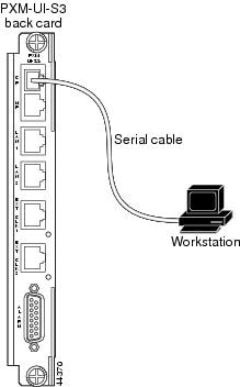
A new switch must be initialized using a console port management session. As shown in Figure 2-1, a console port management session requires a terminal or workstation with a serial connection to the Console Port (CP) port on the PXM45 UI-S3 back card.
Figure 2-1 Workstation Connection to Console Port
To initialize the switch, use the following procedure.
Step 1
Physically connect a terminal or workstation to the PXM45 UI-S3 back card as shown in Figure 2-1.
You can use any personal computer or UNIX workstation with a terminal emulation program that emulates the VT-100.

Note
Step 2
The default switch configuration supports the following settings: 9600 bps, 8 data bits, no parity, 1 stop bit, no hardware flow control.
Step 3
Step 4
Note
Step 5
When startup is complete for an uninitialized switch, it will display the PXM45 backup boot prompt:
pxm45bkup>Step 6
The version number is listed in the 2.0.12 Version Software Release Notes, Cisco WAN MGX 8850 Software and must be entered using the same format listed in the firmware file name. For example, if the firmware filename is pxm45_002.000.001.000_mgx.fw, the firmware version number you will enter is 002.000.001.000.
Step 7
pxm45bkup> sysVersionSet "version"Replace version with the version number for the runtime firmware. For example:
pxm45bkup> sysVersionSet "002.000.001.000"Step 8
pxm45bkup> rebootDuring initialization, the switch will appear to boot twice. When the reboot is complete, the switch displays the Login prompt, which indicates that the firmware is loaded and the switch is ready for configuration.

Tips
Step 9
Login: superuserpassword:unknown.7.PXM.a >
Note
The switch does not display the password during login. When login is complete, the switch prompt appears.
The switch prompt for PXM45 and AXSM cards uses the following format:
nodename.slot.cardtype.state>
Table 2-1 describes the components in the CLI prompt.
Table 2-1 CLI Prompt Components
nodename
The nodename is the name of the node. When a new switch starts up, the node name is set to "unknown." To change the name, see "Setting and Viewing the Switch Name," which appears later in this chapter.
slot
The slot number indicates which card you are configuring. For most general switch configuration procedures, you need to configure the switch using the PXM45 cards in slots 7 or 8. For many line and trunk configuration procedures, you need to modify service modules (such as the AXSM card), which can be in slots 1-6 and 9-14.
cardtype
The cardtype identifies the model of the card, such as PXM or AXSM.
state
The card state is active (a), standby (s), or initialized (i). Cards are labeled as initialized during switch startup.
After initialization, the PXM45 card in the initialized slot becomes active. If a second PXM45 is installed in the other slot, the active PXM45 initiates a runtime firmware load on the other slot. After the runtime firmware loads on the non-active PXM45, the card enters standby mode, ready to take control if the active card fails.
After you log in, the switch maintains your session for 10 minutes (600 seconds) after the last keystroke is entered. If the session is idle longer than 600 seconds, the session is terminated.
Tips
Step 10
unknown.7.PXM.a > timeout <seconds>Replace seconds with the number of seconds you want the session to remain active before it times out. The maximum value is 600. To disable time-out, enter 0 seconds. The switch uses the new timeout value until you terminate the session. Each time a new session is started, the timout value returns to the default value, 600 seconds.
Once you have completed the procedure above, you have established a Command Line Interface (CLI) management session. You can use a CLI management session to configure or monitor the switch.
Starting a CLI Management Session After Initialization
After initialization, you can terminate and start sessions at any time using the terminal or workstation connection to the CP port, which was described in the previous section.
Tips
To start a CLI management session at the CP port for switch configuration and monitoring, use the following procedure.
Step 1
For instructions on preparing the terminal and the connection, refer to the previous section, "Initializing the Switch."
Step 2
Loginprompt does not appear, press Return. TheLoginprompt comes from the switch and indicates that the terminal has successfully connected to the switch.Step 3
Loginprompt appears, enter the login name supplied with your switch, and then enter the password for that login name. For example:Login: superuserpassword:pop20one.7.PXM.a >
Note
The switch does not display the password during login. When login is complete, the switch prompt appears.
The switch prompt for PXM45 and AXSM cards uses the following format:
nodename.slot.cardtype.state>
Table 2-1 describes the components in the switch prompt.
After you log in, the switch maintains your session for 10 minutes (600 seconds) after the last keystroke is entered. If the session is idle longer than 600 seconds, the session is terminated.
Tips
Step 4
unknown.7.PXM.a > timeout <seconds>Replace seconds with the number of seconds you want the session to remain active before it times out. The maximum value is 600. To disable time-out, enter 0 seconds. The switch uses the new timeout value until you terminate the session. Each time a new session is started, the timout value returns to the default value, 600 seconds.
Once you have completed the procedure above, you have established a Command Line Interface (CLI) management session. You can use a CLI management session to configure or monitor the switch.
Ending a CLI Management Session
CLI management sessions automatically terminate after the configured idle time. The default idle time is 600 seconds (10 minutes) and can be changed with the timeout command. To manually end a CLI management session, enter the bye or exit command.
Note
To restart the session after entering the bye or exit command, just press Return, and the switch will prompt you for a username and password.
Entering Commands at the Switch Prompt
The commands in the switch operating system are associated with the cards that are installed in the switch. Before you execute a command, you must select a card that supports the command. The switch displays the currently selected card in the switch prompt. For example, the following switch prompt shows that the PXM45 card in slot 7 is selected:
mgx8850a.7.PXM.a >To select another card in the switch, enter the following command:
mgx8850a.7.PXM.a > cc <slotnumber>Replace slotnumber with the number of the slot in which the card you want to manage is installed. Table 2-2 lists the valid slot numbers for each card type.
Table 2-2 Valid Slot Numbers for Each Card Type
PXM45
7 and 8
AXSM
1-6 and 9-14
After you use the cc command to change cards, verify that you are managing the correct card by viewing the slot number shown in the switch prompt. The following example shows the prompt for an AXSM card in slot 9:
mgx8850a.9.AXSM.a >If you have trouble executing a command, look at the switch prompt to see if you have selected the correct card and type for the command. The following example shows the response to an unrecognized command:
mgx8850a.9.AXSM.a > dspdateERR: unknown command: "dspdate"The dspdate command must be run on a PXM45 card and is not recognized by an AXSM card.
Tips
Because the help command is the only command that begins with he, you can use the abbreviated he command to display help. The following example demonstrates that the switch recognizes partial commands and displays long reports one page at a time.
pop20one.7.PXM.a > heAvailable commands------------------?abortofflinediagabortrevactauditaddaddraddcontrolleraddfltsetaddpnni-nodeaddpnni-summary-addraddpnportaddprfxaddredaddserialifaddtrapmgradduseraesa_pingarpAddarpDeletearpFlushType <CR> to continue, Q<CR> to stop:Because the help report is too long to appear on one screen, it is displayed in pages. Press Return to display the next page, or type q and press Return to cancel the report display.
The following example demonstrates what can appear when a command is entered at the wrong card prompt.
mgx8850a.9.AXSM.a > dspcdsERR: incorrect number of parameters: (not enough)Syntax: dspcdsct <bw|gen|cosb|vcThr|cosThr>bw|gen|cosb|vcThr|cosThr -- bw: Bandwidth parametersgen: policing and CAC parameterscosb: cosb parametersvcThr: vc threshold parameterscosThr: cosb threshold parametersIn the example above, the dspcds command is entered at the AXSM card prompt, but this command is not supported on the AXSM card (although the dspcd command is). Because the command isn't recognized, the switch matches it up to a command that is supported, which is the dspcdsct command. Because the command was entered without parameters, the switch displays an error message and the correct format for entering the dspcdsct command.
Whenever the switch displays an error message, be sure to check the spelling of the command, the parameters entered with the command, and the prompt at which the command was entered.
Getting Command Help
The following sections describe how to display the following types of command help:
•
•
•
Displaying Command Lists
To display a list of all the commands available, enter the help command as follows:
mgx8850a.7.PXM.a > helpTo display a list of commands that include a common set of characters, enter a question mark and the common set of characters as shown in the following example:
pop20one.7.PXM.a > ? ipAvailable commands------------------cliPlugincliPlugoutcnfifipcnfilmiprotocnftrapipdelifipdspifipdspipconntaskdspipifdspipifcachedsptrapipipifconfigpntracevsipktsetipconndebugDisplaying Detailed Command Lists
Detailed command lists display the following additional information for each command:
•
•
•
Note
To enable detailed command lists, enter the clidbxlevel command as shown in the following example:
pop20two.7.PXM.a > clidbxlevel 1Value of cliDbxLevel is now 1After you enter this command, you can display detailed command lists by entering the help command as shown in the following example:
pop20one.7.PXM.a > helpCommand Access Card Log---------------------------------------------------? ANYUSER ANY_STATE -abortofflinediag SERVICE_GP ANY_STATE -abortrev SERVICE_GP ANY_STATE +actaudit SUPER_GP ACTIVE_ONLY +addaddr GROUP1 ACTIVE_ONLY +addcontroller SUPER_GP ACTIVE_ONLY +addfltset GROUP1 ACTIVE_ONLY +addpnni-node SUPER_GP ACTIVE_ONLY +addpnni-summary-addr SUPER_GP ACTIVE_ONLY +addpnport GROUP1 ACTIVE_ONLY +addprfx GROUP1 ACTIVE_ONLY +addred SUPER_GP ACTIVE_ONLY -addserialif SUPER_GP ACTIVE_ONLY -addtrapmgr SUPER_GP ACTIVE_ONLY +adduser GROUP1 ACTIVE_ONLY +aesa_ping SUPER_GP ACTIVE_ONLY +arpAdd SUPER_GP ANY_STATE +arpDelete SUPER_GP ANY_STATE +arpFlush SUPER_GP ANY_STATE +Type <CR> to continue, Q<CR> to stop: (command aborted)
Note
The Access column shows the access level required to execute the command. Access levels are described in "Configuring User Access," which appears later in this chapter.
The Card column identifies the card states during which the command can be executed. Valid card states are active, standby), and initialized. Cards are labeled as initialized during switch startup. The options that appear in the Card column are described in Table 2-3.
If a plus symbol appears in the Log column, each execution of the command is logged. If a minus symbol appears in the column, the command is not logged.
Displaying Command Syntax and Parameters
To display the syntax of a command, enter the command without any parameters. The following example shows the syntax report provided by the switch using the addport command.
pop20two.1.AXSM.a > addportERR: incorrect number of parameters: (not enough)Syntax: addport "<ifNum> <bay.line> <guaranteedRate> <maxRate> <sctID> <ifType>[vpi]"If Number -- number between 1 and 60Line Number -- format bay.lineGuaranteed virtual int. Rate -- rates in cells/sec:Max virtual int. Rate -- for OC48:between 50 and 5651320for OC12:between 50 and 1412830for OC3:between 50 and 353207for T3:between 50 and 96000(PLCP),104268(ADM)for E3:between 50 and 80000SctID -- Port SCT Id between 0 and 255, for default file use 0IfType -- 1: uni 2: nni 3: vnnivpiNum -- vpi between 1 and 4095:used for configuring interface as virtual trunkWhen a parameter is shown between less-than (<) and greater-than (>) symbols, the parameter represents a variable that must be replaced by a value. The values are described below the command syntax.
When the parameter is shown between brackets ([]), it is an optional parameter. If you omit an optional parameter, most commands will use the last value defined for the option. If no value has been assigned to an option, the default value is used.
Note
Configuring User Access
The usernames and passwords supplied with your switch provide access to all switch features, and they allow you to add and delete users and change user passwords.
When configuring user access for the switch, consider the following recommendations:
•
•
•
•
The following sections describe how to add users, change passwords for existing users, delete users, and recover the user cisco password.
Adding Users
The switch supports up to 50 users. When you add users, you must specify the following for each user:
•
•
•
The user name and password identify the user and determine the user's access level for switch management.
An access level must be assigned to a user when the user is added to the switch. The access levels listed in Table 2-4 are used throughout this guide to indicate the level of access required to execute a command or complete a procedure. These access levels are also called access privileges. If a user has access privileges at a lower level than a command requires, the user cannot execute the command. If the user has access privileges at the level required or at a higher level, the user can execute the command.
To add a user to the switch, use the following procedure.
Step 1
Step 2
mgx8850a.7.PXM.a >adduser <username> <accessLevel>Enter the username using 1-12 alphanumeric characters. Specify the access level by entering one of the levels defined in Table 2-4.
Note
Tips
If you enter the command correctly, the switch prompts you for a password.
Step 3
Step 4
This completes the addition of the new user.
Step 5
Step 6
Tips
Changing Your Own User Password
Use the cnfpasswd command to change your own password.
Note
To change your own password with the cnfpasswd command, use the following procedure.
Step 1
Step 2
mgx8850a.7.PXM.a >cnfpasswdStep 3
Step 4
Step 5
This completes the change of password.
Step 6
Changing User Access Levels and Passwords with cnfuser
After you create a user, you can change that user's access level or password using the cnfuser command.
Note
To change the user level or password of a switch user, use the following procedure.
Step 1
Step 2
mgx8850a.7.PXM.a >cnfuser -u <username> [-p <password>] [-l <accessLevel>]Replace username with the name of the user for whom you are making the change.
If you are changing the password, specify the -p option and enter a password containing 5-15 characters. If you are changing the user access level, specify the -l (lowercase L) option and enter the appropriate access level as shown in Table 2-4.
Note
Step 3
Step 4
The dspusers command displays all the usernames and the access level for each user as shown in the following example:
pop20two.7.PXM.a > dspusersUserId AccessLevel-------------------------cisco CISCO_GPservice SERVICE_GPsuperuser SUPER_GPjbowman GROUP1
Deleting Users
To delete a user, use the following procedure.
Step 1
Step 2
mgx8850a.7.PXM.a >deluser <username>Enter the username using 1 to 12 alphanumeric characters.
This completes the deletion of a user.
Step 3
Resetting the User cisco Password
If you lose or forget your password for switch access, you should ask a user with a higher access level to reset your password using the cnfuser command. If you don't have any passwords for any access levels, you can use the following password recovery procedure to reset the password for user cisco. This procedure resets the user cisco password to cisco and leaves all other passwords unchanged (You can change the other passwords with the cnfuser command after logging in as user cisco.).
Step 1

Caution
Step 2
Step 3
Step 4
Step 5
Setting and Viewing the Switch Name
The switch name identifies the switch you are working on, which is important when you are managing multiple switches. The current switch name appears in the CLI prompt when you are managing a PXM45 cards and service modules. To change the switch name, use the following procedure.
Step 1
Step 2
unknown.7.PXM.a > cnfname <node name>Enter up to 32 characters for the new node name, and since the node name is case-sensitive, be sure to use the correct case. For example:
unknown.7.PXM.a > cnfname pop20twoThis node name will be changed to pop20two. Please Confirmcnfname: Do you want to proceed (Yes/No)? ycnfname: Configured this node name to pop20two Successfully.pop20two.7.PXM.a >The new name appears immediately in the next CLI prompt.
Viewing and Setting the Switch Date and Time
The switch date and time is appended to event messages and logs. To assure that events are properly time stamped, use the following procedure to view and change the date and time.
Step 1
Step 2
mgx8850a.7.PXM.a > dspdateStep 3
mgx8850a.7.PXM.a > cnfdate <mm/dd/yyyy>Step 4
mgx8850a.7.PXM.a > cnftmzn <timezone>Replace timezone with GMT for Greenwich Mean Time, EST for Eastern Standard Time, CST for Central Standard Time, MST for Mountain Standard Time, PST for Pacific Standard Time. Options 2 through 5 are for switches located in the Western Hemisphere. If your switch is located outside the Western Hemisphere, select GMT and use the next step to specify an offset from GMT.
Step 5
mgx8850a.7.PXM.a > cnftmzngmt <timeoffsetGMT>Replace timeoffsetGMT with the offset in hours from GMT. Enter a number in the range of -12 to +12.
Step 6
mgx8850a.7.PXM.a > cnftime <hh:mm:ss>Replace hh with the hour of the day (0-23), mm with the minute of the hour (0-59), and ss with the number of seconds in the minute (0-60).
Step 7
Configuring the PNNI Controller
The PNNI controller simplifies switch configuration by using the PNNI protocol to discover call routes in an ATM network. Without the PNNI controller, each route through the network would have to be defined manually. "Managing PNNI Routes," provides more information on PNNI. This section describes how to enable and configure the PNNI controller for the switch.
Note
To enable and configure the PNNI controller, enter the following command:
mgx8850a.7.PXM.a > addcontroller <cntrlrId> i <cntrlrType> <lslot> [cntrlrName]Table 2-5 describes the parameters for the addcontroller command.
Tips
To display the PNNI controller configuration, enter the dspcontrollers command:
mgx8850a.7.PXM.a > dspcontrollersConfiguring BITS Clock Sources
The "Network Clock Source Plan" section in "Preparing for Configuration," introduces Building Integrated Timing System (BITS) clock sources and provides guidelines for developing a network clock source plan. When the network clock source plan requires BITS clock sources on the switch, you can use the procedure in this section to configure the BITS clock connections.
Figure 2-2 shows how BITS clock sources connect to the PXM45 UI-S3 back card.
Figure 2-2 BITS Clock Source Ports on PXM UI-S3 Back Card
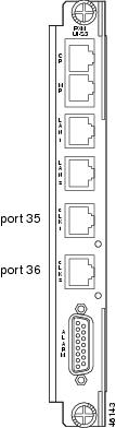
The PXM45-UI-S3 clock source ports can be used to receive clock signals from either T1 or E1 lines; the card does not support both line types simultaneously. These clock ports support stratum levels 1-3.
The PXM45 provides a revertive function that you can enable when the primary clock source is received on a BITS clock port. A clock source failure occurs when the signal is lost or the clock source has drifted out of the range specified for its stratum. When the revertive function is enabled, the switch automatically reverts to the primary BITS clock after the primary source operates within specification for 12 seconds.
The following procedure describes how to configure the switch to use clock sources on the BITS clock ports.
Step 1
Step 2
mgx8850a.7.PXM.a > cnfclksrc <priority> [shelf.]slot.port -bits {e1|t1} [-revertive
{enable|disable}]
Table 2-6 describes the parameters for this command.
Step 3
Step 4
The following command example shows how to configure a primary E1 external clock source at the upper connector of the PXM45-UI-S3. Note the command punctuation.
mgx8850a.7.PXM.a > cnfclksrc primary 7.35 -bits e1The next example configures a primary network clock source and enables the revertive option.
mgx8850a.7.PXM.a > cnfclksrc primary 7.36 -bits e1 -revertive enableThe last example disables the revertive function for an E1 BITS clock.
mgx8850a.7.PXM.a > cnfclksrc primary 7.36 -bits e1 -revertive disableSetting the PNNI Node Address
The PNNI node address is the switch ATM address that is advertised throughout the PNNI network. The default PNNI node address is shown in Figure 2-3.
Figure 2-3 Default PNNI Node Address
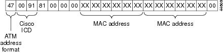
The first byte (47) of the default address identifies the address as an International Code Designator (ICD) ATM End Station Address (AESA). The second and third bytes (0091) are the globally unique ICD assigned to Cisco, and the next four bytes (81000000) are identical for all MGX 8850 switches. The unique portion of the default node address is the 6-byte MAC address, which is used in bytes 8 through 13 and again in bytes 14 through 19. Byte 20, which is the selector byte, is set to 00 by default.
Cisco assigns a unique MAC address to each PXM45 when it ships from the factory, and this is used to create a unique PNNI node address. For evaluation purposes, the Cisco unique ATM addresses are acceptable. For production networks, however, Cisco recommends that you change the PNNI node address to an address that conforms to the address plan for your business. For more information on creating an address plan, see "Guidelines for Creating an ATM Address Plan," in "Preparing for Configuration."
Caution
The following procedure describes how to set the PNNI node address for the switch.
Step 1
Step 2
pop20one.7.PXM.a > cnfpnni-node node-index -enable falseThe node-index uniquely defines a single PNNI node within the switch. The switch allows you to define multiple PNNI nodes within the switch. Initially, there is just one PNNI node, and its index number is 1. To disable the default PNNI node, replace node-index with 1.
Step 3
pop20one.7.PXM.a > cnfpnni-node node-index [-atmAddr atm-address] [-level level]
[-nodeId nodeId]
Table 2-7 describes the parameters for this command.
Note
Table 2-7 Parameter Descriptions for the cnfpnni-node Command
node-index
1 to 4,294,967,299
This number uniquely defines a single PNNI node within the switch. The switch allows you to define multiple PNNI nodes within the switch. Initially, there is just one PNNI node, and its index number is 1. To change the PNNI node address for the default PNNI node, enter 1.
atm-address
Enter a 20-byte ATM address for the PNNI node. This address should conform to your ATM address plan. For more information, see "Guidelines for Creating an ATM Address Plan," in "Preparing for Configuration."
level
1 to 104
Enter the PNNI level for the peer group in which the switch operates. The default value is 56, and this value remains unchanged if you do not enter a new value. For more information on selecting a PNNI level, see "Guidelines for Creating an ATM Address Plan," in "Preparing for Configuration."
nodeId
Enter a 22-byte node ID as shown in Figure 2-4. The level should match the level set with the -level option and the ATM address should match the address set with the -atmAddr option.
Figure 2-4 Node ID

Step 4
pop20one.7.PXM.a > cnfpnni-node node-index -enable trueReplace node-index with the value you used when disabling and reconfiguring the PNNI node.
Step 5
pop20one.7.PXM.a > dsppnni-node node-indexReplace node-index with the value you used when reconfiguring the PNNI node. The switch displays a report similar to the following:
pop20two.7.PXM.a > dsppnni-node 1node index: 1 node name: pop20twoLevel............... 56 Lowest.............. trueRestricted transit.. off Complex node........ offBranching restricted onAdmin status........ up Operational status.. upNon-transit for PGL election.. offNode id...............56:160:47.00918100000000001a531c2a.00001a531c2a.01ATM address...........47.00918100000000001a531c2a.00001a531c2a.01Peer group id.........56:47.00.9181.0000.0000.0000.0000.00
Setting the Switch IP Addresses
The switch uses two type of IP addresses for Ethernet LAN access:
•
•
The following sections describe how to set these addresses. For information on how the switch uses these addresses and how to choose the addresses to set, refer to "Preparing for Configuration."
Note
Setting the Boot IP Address
The boot IP address is the address a PXM45 card uses when it first starts up. If the switch cannot fully start, this IP address can be used to access the switch in boot mode. When the switch is properly configured (with different addresses set for the boot IP and disk IP addresses), the boot IP address can also be used to directly access the standby PXM45 card, while the disk IP address can be used to access the active PXM45.
Note
To set the boot IP address, use the bootchange command, which allows you to also define a remote boot location, a default gateway IP address, and a username and password for the remote boot location.
Step 1
Step 2
pop20two.7.PXM.a > bootchange'.' = clear field; '-' = go to previous field; ^D = quitboot device : lnPciIn the previous example, the switch is waiting for you to take action on the boot device option. You can press period (.) to clear the current value (lnPci), press minus (-) to go back to the previous field (although this is the first of 14 fields), or press Return to accept the current value and display the next option. The following example shows all options:
pop20two.7.PXM.a > bootchange'.' = clear field; '-' = go to previous field; ^D = quitboot device : lnPciprocessor number : 0host name : bootserverfile name : /users/jbowman/mgx8850/2.1/pxm45_002.001.000.000_mgx.fwinet on ethernet (e) : 172.29.52.88inet on backplane (b):host inet (h) : 171.71.153.27gateway inet (g) : 172.29.52.1user (u) : rliftp password (pw) (blank = use rsh):flags (f) : 0x0target name (tn) : pxm45-h10startup script (s) :other (o) :
Note
Step 3
Step 4
inet on ethernet (e) : 172.29.52.88 172.29.52.108The 172.29.52.88 address appeared as part of the prompt. If no address had been previously defined, no text would appear after the colon. In this example, 172.29.52.108 is the new boot IP address.
Step 5
Step 6
Step 7
Note
Setting the Node or Disk IP Address
The node or disk IP address is the address an active PXM45 card uses during normal switch operation. This address serves as the node IP address, but it is also called the disk IP address in the CLI. The node IP address can be set to match the boot IP address when only one IP address is available, or it can be set to a unique address to support access to the standby PXM45 during regular operation. For more information on how the boot and node IP addresses are used, refer to "Preparing for Configuration."
To set the node IP address, use the ipifconfig command as described in the following procedure.
Step 1
Step 2
mgx8850a.7.PXM.a> dspipif lnPci0
Note
In the IP Interface Configuration Table, look for an Internet address entry under the lnPci entry. If an IP address is configured, you can use that address and skip the rest of this procedure. However, if the address has not been entered or is incompatible with your network, you must configure a valid IP address as described in the next step.
Step 3
mgx8850a.7.PXM.a> ipifconfig lnPci0 <IP_Addr> <netmask Mask>Replace IP_Addr with the IP address you want this port to use, and replace Mask with the network mask used on this network.
Tips
Note
Setting and Viewing the SPVC Prefix
The SPVC node prefix is the ATM prefix that PNNI advertises for all SPVCs and SPVPs on this node. The ATM address for each SPVC and SPVP is the combination of the SPVC prefix and a port identification number.
You can configure one SPVC node prefix per node. The default SPVC prefix is set to match the first 13 bytes of the default ATM address, which is shown in Figure 2-3. In most cases, if you change the PNNI node address, you should change the SPVC prefix to match the new ATM address.
Note
To set the SPVC prefix, use the following procedure.
Note
Step 1
Step 2
pop20two.7.PXM.a > dspspvcprfxThe switch response is similar to the following:
pop20two.7.PXM.a > dspspvcprfxSPVC Node Prefix: 47.00918100000000001a531c2a
Tips
Step 3
pop20two.7.PXM.a > cnfspvcprfx <prefix>Replace prefix with the 13-byte prefix you want to use.
Note
Step 4
Configuring for Network Management
The MGX 8850 switch includes a Simple Network Management Protocol (SNMP) agent that you can configure for communications with a network management station such as Cisco WAN Manager (CWM) or a third-party SNMP manager. When configured for SNMP management, the switch accepts configuration commands from management stations and sends status and error messages to the management station.
Typically, CWM operates on a workstation connected to an IP network and uses IP over ATM connections to connect to the MGX 8850 switches. For information on establishing this type of access, refer to "Setting Up ATM WAN Connections" in "Supporting and Using Additional CLI Access Options."
To support the auto-discovery feature of CWM, ILMI should be brought up on all links between the CWM workstation and the switches it will manage. For information on bringing up ILMI, refer to"Configuring ILMI on a Port" in "Provisioning AXSM Communication Links."
To configure information about a switch in the local SNMP agent, use the following procedure.
Step 1
Step 2
mgx8850a.7.PXM.a > cnfsnmp community [password]If the password parameter is not specified, the password becomes "private."
Step 3
mgx8850a.7.PXM.a > cnfsnmp location [location]If the location parameter is not specified, the location is set to null (no text). The location value is sent to SNMP managers when information is requested about the sysLocation MIB object.
Step 4
mgx8850a.7.PXM.a > cnfsnmp contact [contact]If the contact parameter is not specified, the location is set to null (no text). The contact value is sent to SNMP managers when information is requested about the sysContact MIB object.
Step 5
pop20one.7.PXM.a > dspsnmppop20one System Rev: 02.00 Jan. 14, 2001 17:47:50 GMTMGX8850 Node Alarm: MAJORCommunity: privateSystem Location: Tech Docs LabSystem Contact jbowman
 Feedback