Provisioning
Available Languages
Table Of Contents
Provisioning AXSM Communication Links
Quickstart Provisioning Procedures
Trunk Configuration Quickstart
SPVC and SPVP Configuration Quickstart
IISP Link Configuration Quickstart
Virtual Trunk Configuration Quickstart
Feeder Configuration Quickstart
Configuring Port Resources Using Partitions
Selecting the Port Signaling Protocol
Verifying PNNI Trunk Communications
Verifying End-to-End PNNI Communications
Defining Destination Addresses for IISP Links
Assigning Static ATM Addresses to Destination Ports
Configuring ILMI Traps and Signaling
Configuring ILMI Automatic Configuration
Configuring ILMI Dynamic Addressing
Starting ILMI with the Default or Existing Values
Configuring the Slave Side of SPVCs and SPVPs
Configuring the Master Side of SPVCs and SPVPs
Configuring AXSM Line Clock Sources
Provisioning AXSM Communication Links
This chapter describes how to add ATM ports and connections to the physical lines defined in "Preparing AXSM Cards and Lines for Communication." This chapter explains how to provision the following types of connections on the MGX 8850 switch:
•
Switched Virtual Circuit (SVC)
•
•
•
•
The configuration differences between these different types of connections are often as simple as an additional command or a different set of command options. To eliminate redundancy and help experienced users complete configuration procedures quickly, this chapter uses configuration quickstarts and task descriptions to explain how to configure these connections.
The first time you configure a connection type, use the quickstart procedure to see the order of tasks to complete, and then look to the task descriptions for detailed instructions on how to complete the tasks. As you get more experience configuring connections, you can look up fewer tasks.

Tips

Note
Note
Quickstart Provisioning Procedures
The following sections present abbreviated procedures that you can use to provision the switch.
Trunk Configuration Quickstart
ATM trunks connect the switch to other ATM switches in the core ATM network. The quickstart procedure in this section provides a summary of the tasks required to configure ATM trunks on the MGX 8850 switch. This procedure is provided as an overview and as a quick reference for those who have previously configured these types of connections.
Note
Step 1
Start a configuration session.
Note: To perform all the procedures in this quickstart procedure, you must log in as a user with GROUP1 privileges or higher.
Step 2
Prepare AXSM cards and lines as described in "Preparing AXSM Cards and Lines for Communication."
Step 3
Related commands:
dspportsAdd and configure ATM ports. This step establishes ATM communications between two ATM devices.
Specify NNI for interswitch trunks and VNNI for virtual trunks.
See "Adding ATM Ports," which appears later in this chapter.
Step 4
Related commands:
dsppartsdsppartcnfpartAdd and configure partitions. This step configures one or more service partitions, which can be used to control how trunk resources are allocated to different services.
See "Configuring Port Resources Using Partitions," which appears later in this chapter.
Step 5
Related commands:
dsppnportsdsppnport <portid>dsppnportsig <portid>Define the signaling protocol used on the trunk. The default signaling protocol is UNI Version 3.1.
Specify pnni10 for PNNI trunks and either iisp30 or iisp31 for IISP trunks. The command for configuring a feeder trunk is:
pop20two.7.PXM.a > cnfpnportsig <portid> -cntlvc <ip>See "Selecting the Port Signaling Protocol," which appears later in this chapter.
Step 6
When both ends of the link are configured, verify PNNI communications between the two ends. In the dsppnni-link report, there should be an entry for the port for which you are verifying communications. The Hello state reported should be twoWayInside and the Remote note ID should display the remote node ATM address after the second colon.
See "Verifying PNNI Trunk Communications," which appears later in this chapter.
Step 7
Related commands:
dspportsdspilmisThis step is optional. Configure and start ILMI on trunks where you want to support Cisco WAN Manager or use ILMI features.
See "Configuring ILMI on a Port," which appears later in this chapter.
Line Configuration Quickstart
ATM Lines connect the switch to ATM end devices, which serve as the boundary between the ATM network and other communications paths or networks. Typical end devices include ATM routers and multiservice concentrators.
The quickstart procedure in this section provides a summary of the tasks required to configure ATM lines on the MGX 8850 switch. This procedure is provided as an overview and as a quick reference for those who have previously configured these types of connections.
Note
Step 1
Start a configuration session.
Note: To perform all the procedures in this quickstart procedure, you must log in as a user with GROUP1 privileges or higher.
Step 2
Prepare AXSM cards and lines as described in "Preparing AXSM Cards and Lines for Communication."
Step 3
Related commands:
dspportsAdd and configure ATM ports. This step establishes ATM layer two communications between two ATM devices.
Specify UNI for ATM lines.
See "Adding ATM Ports," which appears later in this chapter.
Step 4
Related commands:
dsppartsdsppartcnfpartAdd and configure partitions. This step configures one or more service partitions, which can be used to control how line resources are allocated to different network controllers.
See "Configuring Port Resources Using Partitions," which appears later in this chapter.
Step 5
Bring down the port so it can be configured. The next three steps require this.
Step 6
Related commands:
dsppnportsdsppnport <portid>dsppnportsig <portid>Define the signaling protocol used on the line. The default signaling protocol for UNI lines is UNI Version 3.1.
Specify uni30, uni31, or uni40.
See "Selecting the Port Signaling Protocol," which appears later in this chapter.
Step 7
Related commands:
dsppnportsdspaddr <portid>deladdr <options>Configure static ATM addresses for ports that require them.
See "Assigning Static ATM Addresses to Destination Ports," which appears later in this chapter.
Step 8
Related commands:
cnfaddrreg <portid> yesdspprfx <portid>If dynamic addressing is to be used on a port, define an ATM address prefix that ILMI can use when assigning addresses.
See "Configuring ILMI Dynamic Addressing," which appears later in this chapter.
Step 9
Bring up port after configuration is complete.
Step 10
Related commands:
dspportsdspilmisConfigure and start ILMI on the port. This step is required for dynamic addressing and the ILMI automatic configuration feature. Otherwise, it is optional.
See "Configuring ILMI on a Port," which appears later in this chapter.
SVC Configuration Quickstart
Switched Virtual Circuits (SVCs) are the solution for on-demand connections. They are set up as needed and torn down when no longer needed. To enable this dynamic behavior, SVCs use signaling. End systems request connectivity to other end systems and, provided that the requested services are available, the connection is set up at the time of the request. When idle, an SVC is taken down to save network bandwidth.
MGX 8850 switches use the PNNI protocol to develop a logical map of the network. This logical map allows switches to work together to determine how to set up SVCs through the network. PNNI enables automatic SVC configuration, which greatly reduces the time required to set up new networks.
Because the switch automatically sets up SVCs, you do not have to configure SVC routes. However, the switch must be configured correctly before it can set up SVCs. The following quickstart procedure summarizes the tasks required to enable SVC communications. With the exception of CPE configuration, all these tasks are described in this chapter.
Note
Step 1
See "Trunk Configuration Quickstart," which appears earlier in this chapter.
Configure the trunks that link the switches through which the ATM end stations connect.
Step 2
Verify PNNI connectivity between nodes pairs that will host SVCs.
See "Verifying End-to-End PNNI Communications," which appears later in this chapter.
Step 3
See "Line Configuration Quickstart," which appears earlier in this chapter.
Configure lines for the ATM end stations at each end of the SVC, and assign either static or dynamic addressing to each line.
Step 4
See the CPE documentation.
Configure CPE devices for line communications with the MGX 8850 switch.
Step 5
This optional step displays the SVC connections that are operating.
See "Displaying SVCs," in Chapter 6, "Switch Operating Procedures."
It is beyond the scope of this guide to describe how to configure each model of CPE to communicate with the MGX 8850 switch. To complete this configuration, you will need to learn the capabilities of the CPE and the MGX 8850 switch and define a set of communications parameters that are supported by both devices. For example, the MGX 8850 switch supports UNI 3.1 communications, but if the CPE does not, you'll need to select a signaling protocol (such as UNI 3.0) that is supported by both devices.
Once all the requirements have been met for SVC connections, CPE devices can establish SVC connections to other CPE devices on the same switched network.
SPVC and SPVP Configuration Quickstart
A Soft Permanent Virtual Circuit (SPVC) is a Permanent Virtual Circuit (PVC) that can be rerouted using the Private Network-to-Network Interface (PNNI) Version 1.0 protocol. As with PVCs, SPVCs are full-time connections. A PVC, however, uses a predefined circuit path and will fail if the path is interrupted. Using the PNNI protocol, SPVCs can be rerouted to avoid failed communication links or to use links that offer better bandwidth.
A Soft Permanent Virtual Path (SPVP) is a permanent virtual path that can be rerouted using the Private Network-to-Network Interface (PNNI) Version 1.0 protocol. The difference between an SPVC and an SPVP is that the SPVP supports multiple virtual circuits, whereas a SPVC is by definition a single virtual circuit. As with SPVCs, when an SPVP fails, PNNI can determine if an alternate route exists and reroute the connection.
The quickstart procedure in this section provides a summary of the tasks required to configure SPVCs and SPVPs on the MGX 8850 switch. This procedure is provided as an overview and as a quick reference for those who have previously configured these types of connections.
Step 1
Start a configuration session.
Note: To perform all the procedures in this quickstart procedure, you must log in as a user with SUPER_GP privileges or higher.
Step 2
See "Trunk Configuration Quickstart," which appears earlier in this chapter.
Configure the trunks that link the switches to which the ATM end stations connect.
Step 3
Verify PNNI connectivity between the two nodes that will host the SPVC or SPVP end points.
See "Verifying End-to-End PNNI Communications," which appears later in this chapter.
Step 4
See "Line Configuration Quickstart," which appears earlier in this chapter.
Configure lines for the ATM end stations at each end of the SPVC or SPVP, and assign either static or dynamic addressing to each line.
Step 5
Related commands:
dspconsdspcon <ifNum> <vpi> <vci>Configure the slave side of an SPVC.
See "Configuring SPVCs and SPVPs," which appears later in this chapter.
Step 6
Related commands:
dspconsdspcon <ifNum> <vpi> <vci>Configure the master side of an SPVC.
See "Configuring SPVCs and SPVPs," which appears later in this chapter.
IISP Link Configuration Quickstart
The quickstart procedure in this section provides a summary of the tasks required to configure IISP links on the MGX 8850 switch. This procedure is provided as an overview and as a quick reference for those who have previously configured these types of connections.
Step 1
Start a configuration session.
Note: To perform all the procedures in this quickstart procedure, you must log in as a user with SUPER_GP privileges or higher.
Step 2
See "Trunk Configuration Quickstart," which appears earlier in this chapter.
Configure the ports at each end of the IISP link.
When setting the signaling protocol with the cnfpnportsig command, be sure to specify iisp30 or iisp31.
Step 3
Add destination addresses to each end of the trunk.
See "Defining Destination Addresses for IISP Links," which appears later in this chapter.
Step 4
Add static addresses to destination ports. This step is required when addresses are not dynamically assigned to the CPE at the destination ports.
See "Assigning Static ATM Addresses to Destination Ports," which appears later in this chapter.
Virtual Trunk Configuration Quickstart
Virtual trunks are introduced in the "Multiservice Edge Aggregation" section of "Preparing for Configuration." Figure 4-1 shows illustrates how a virtual trunk is configured.
Figure 4-1 Virtual Trunk Configuration
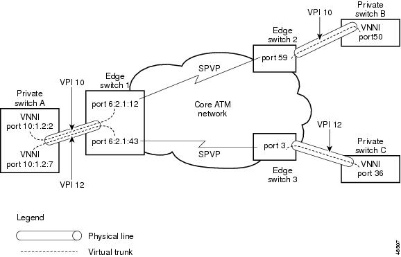
Figure 4-1 shows sample configuration data that you can use as an example when following the quickstart procedure below.
To set up a virtual trunk, the following tasks have to be completed:
•
•
The MGX 8850 switch supports:
•
•
Note
The following quickstart procedure provides a summary of the tasks required to configure virtual trunks on the MGX 8850 switch. This procedure is provided as an overview and as a quick reference for those who have previously configured these types of connections.
Step 1
Start a configuration session.
Note: To perform all the procedures in this quickstart procedure, you must log in as a user with SUPER_GP privileges or higher.
Step 2
See "Trunk Configuration Quickstart," which appears earlier in this chapter.
Configure the virtual trunk end ports at the private switches. When configuring the trunk, do the following:
•
•
•
Step 3
See "Trunk Configuration Quickstart, which appears earlier in this chapter.
Configure the virtual trunk end ports at each core edge node. When configuring these ports, do the following:
•
•
•
Step 4
See "Configuring SPVCs and SPVPs," which appears later in this chapter.
Fore each virtual trunk, configure an SPVP between the virtual trunk UNI ports at each edge of the core network.
Feeder Configuration Quickstart
The quickstart procedure in this section provides a summary of the tasks required to configure a connection from an MGX 8850 Release 1 feeder, through one or more MGX 8850 Release 2 switches, and to a remote feeder or CPE. This procedure is provided as an overview and as a quick reference for those who have previously configured these types of connections.
Note
Step 1
Start a configuration session on the MGX 8850 Release 2 switch. This will be the local routing switch that connects to the feeder.
Note: To perform all the procedures in this quickstart procedure, you must log in as a user with GROUP1 privileges or higher.
Step 2
See "Trunk Configuration Quickstart" or "Line Configuration Quickstart," both of which appear earlier in this chapter.
Configure the local routing switch port that leads to the feeder. When configuring the line, do the following:
•
•
•
pop20two.7.PXM.a > cnfpnportsig <portid> -cntlvc <ip>Replace ip with the IP address assigned to ATM0.
Step 3
Related commands:
dspfdr <ifnum>Define the local routing switch port as a feeder port.
See "Defining a Feeder Port," which appears later in this chapter.
Step 4
See the MGX 8850 Release 1 documentation.
At the MGX 8850 Release 1 feeder, use the addcon command to add a connection on the link to the MGX 8850 Release 2 switch.
Step 5
Configure the port on the remote routing switch that terminates calls in the core network. If the remote routing switch port connects to a feeder, repeat Steps 2 and 3 to configure the remote feeder trunk. If the remote routing switch port connects to CPE, configure the port for UNI communications.
Step 6
Related commands:
dspconsCreate an SPVC from the local routing switch feeder port to the remote routing switch termination port.
See "Configuring SPVCs and SPVPs."
Adding ATM Ports
In the previous chapter, you brought up physical lines by specifying the correct line port number. The line ports correspond to line connectors on the switch back cards. Bringing up a line establishes minimal connectivity between two nodes. When you add an ATM port to a line, you enable ATM communications over the line.
Each line can support UNI, NNI, or VNNI ports. UNI ports are used for lines that connect to PBXs, ATM routers, and other ATM devices that connect to the core ATM network through the MGX 8850 switch. NNI ports are used for trunks that connect to other core ATM network devices, such as the MGX 8850 switch. VNNI ports support virtual trunk connections between two ATM end stations.
You must configure one ATM port for each line or trunk to enable ATM communications over that link. You define the port type (UNI, NNI, or VNNI) when you add the ATM port to the line or trunk.
To add an ATM port to a line, use the following procedure.
Step 1
Step 2
mgx8850a.10.AXSM.a > dsplns
Tips
Step 3
mgx8850a.10.AXSM.a > dspportsThis command displays all ports on the AXSM card in the ifNum (interface number) column. The interfaces listed include UNI, NNI, and VNNI ports. Pay attention to the port numbers already in use. When you add a port, you must specify a port number that is unique on the AXSM card. For example, if port number 2 is assigned to line 2.1 (bay 2, line 1), you cannot use port 2 on any other line on that AXSM card.
Note
Step 4
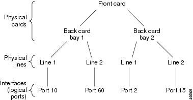
mgx8850a.10.AXSM.a > addport <ifNum> <bay.line> <guaranteedRate> <maxRate> <sctID>
<ifType> [vpi]
Table 4-1 lists the parameter descriptions for adding ports. Figure 4-2 shows the relationship between logical interface numbers and physical lines.
Table 4-1 Parameters for addport Command
ifNum
An ATM port is also called an interface. An ATM port is defined by its slot, bay, line, and interface numbers. You do not have to enter a slot number during port configuration because you identify the slot number when you select the card.
Enter a number from 1 to 60 to identify this interface. The interface number must be unique on the card to which it is assigned. For UNI and NNI ports, you can assign one logical interface per line. For VNNI ports (for virtual trunks), you can assign multiple logical interfaces per line.
bay
Replace bay with 1 if the line is connected to a back card in the upper bay, or replace it with 2 if the line is connected to a back card in the lower bay. Remember that the bay number is always 1 for an AXSM-1-2488.
line
Replace line with the number that corresponds to the back card port to which the line is connected. Table 4-2 lists the valid line numbers for each AXSM card.
guaranteedRate
Enter the minimum rate for the port in cells per second (cps).
Note that in this release, the guaranteedRate value should equal the maxRate value.
The rate ranges are as follows:
OC48: 50 to 5651320
OC12: 50 to 1412830
OC3: 50 to 353207
T3: 50 to 96000 (PLCP) or 104268 (ADM)
E3: 50 to 80000
maxRate
Enter the maximum rate for the port in cps.
Note that in this release, the maxRate value should equal the guaranteedRate value.
The rate ranges are as follows:
OC48: 50 to 5651320
OC12: 50 to 1412830
OC3: 50 to 353207
T3: 50 to 96000 (PLCP) or 104268 (ADM)
E3: 50 to 80000
sctID
Enter the port SCT number (0-255). The Cisco policing SCT ID is 2, and the non-policing ID is 3.
ifType
Enter a number that indicates the interface type. Enter 1 for UNI, 2 for NNI, and 3 for VNNI, which defines a virtual trunk port.
vpi
When the ifType parameter is set to 3 for VNN, enter a VPI number for the virtual trunk in the range of 1 to 4095. This parameter is not required for UNI and NNI ports.
Table 4-2 AXSM Card Types
AXSM-16-155
1-8
1, 2
AXSM-4-622
1-2
1, 2
AXSM-1-2488
1
1
AXSM-16-T3E3
1-8
1, 2
Figure 4-2 Relationship Between Cards, Bays, Lines, and Logical Interface Numbers
The following example command defines a line port as a UNI T3 line:
mgx8850a.10.AXSM.a > addport 1 1.1 96000 96000 1 1The following example command defines a line port as an OC48 NNI trunk:
mgx8850a.10.AXSM.a > addport 2 2.1 5651328 5651328 2 2Step 5
mgx8850a.10.AXSM.a > dspportsThis command displays all configured ports on the AXSM card. Port numbers are listed in the ifNum (interface number) column. If you want to view information on a particular port, note the number of that port.
Step 6
mgx8850a.10.AXSM.a > dspport <ifNum>Replace ifNum with the number assigned to the port during configuration. The following example shows the report for this command:
pop20two.1.AXSM.a > dspport 1Interface Number : 1Line Number : 1.1Admin State : Up Operational State : UpGuaranteed bandwidth(cells/sec): 1412830 Number of partitions: 1Maximum bandwidth(cells/sec) : 1412830 Number of SPVC : 0ifType : NNI Number of SPVP : 0Port SCT Id : 2VPI number(VNNI only) : 0 Number of SVC : 2
Tips
Configuring Port Resources Using Partitions
After you add a line or trunk port, you need to configure additional parameters that define how the port resources are used by the switch network controllers. These parameters include the following:
•
•
•
•
In this release, the MGX 8850 switch supports only the PNNI controller (see "Configuring General Switch Features"). Some parameters, such as the ranges for VPI and VCI values, are provided so that the port resources can be divided between two or more controllers. Because the current software supports one controller, you can assign all port VPI, VCI, and bandwidth resources to the PNNI controller. However, since the switch supports a maximum number of connections, you may choose to limit the number of connections allowed on a single port. For example, if you allowed the maximum number of connections on all ports, two or three very busy ports could use all available connections and disable communications on all other ports.
The port resources are defined as a group in a controller partition, which is dedicated to a single port controller. You must define one controller partition for the PNNI controller, and you must configure one resource partition for each port that uses the PNNI controller. Figure 4-3 presents a simplified view of the relationship between the port controller, controller partition, and resource partitions.
Figure 4-3 Relationship of Port Controller, Controller Partition, and Resource Partitions

Figure 4-3 shows that the single controller partition connects to the PNNI port controller and to the resource partitions. After you create a port, you must create a resource partition for that port to select the PNNI controller and define which ATM resources the port will use. You do not have to create the controller partition, as it is automatically created when you create the first resource partition. The important concept is that the same controller partition, and therefore the same partition ID, is used for all resource partitions on the same AXSM card. The PNNI controller is identified by the controller ID and the controller partition is identified by the partition ID. The resource partitions are identified by specifying the partition ID in combination with the port ID (interface number).
To create a resource partition for a port, use the following procedure.
Step 1
Note
Step 2
mgx8850a.10.AXSM.a > dspportsThis command displays all ports on the AXSM card in the ifNum (interface number) column.
Step 3
mgx8850a.10.AXSM.a > addpart <ifNum> <partId> <ctrlrId> <egrminbw> <egrmaxbw> <ingminbw>
<ingmaxbw> <minVpi> <maxVpi> <minVci> <maxVci> <minConns> <maxConns>
Table 4-3 describes the parameters for this command.
Table 4-3 Parameters for the addpart Command
ifNum
Interface number or port number. This number identifies the port this resource partition configures. Enter the interface number that was assigned to the port when it was configured (see "Adding ATM Ports").
partId
Partition identification number. Enter a number in the range of 1 to 20. On an AXSM card, this number must be the same for all ports that use the PNNI controller.
ctrlrId
Controller identification number. Enter the number 2 to specify the PNNI controller (see "Configuring the PNNI Controller," in "Configuring General Switch Features").
egrminbw
Egress minimum bandwidth. Enter the minimum percentage of the outgoing port bandwidth that you want assigned to the PNNI controller. One percent is equal to 0.00001 units. For example, an egrminbw of 1000000 = 100%.
egrmaxbw
Egress maximum bandwidth. Enter the maximum percentage of the outgoing port bandwidth that you want assigned to the PNNI controller. One percent is equal to 0.00001 units. For example, an egrminbw of 250000 = 25%.
ingminbw
Ingress minimum bandwidth. Enter the minimum percentage of the incoming port bandwidth that you want assigned to the PNNI controller. One percent is equal to 0.00001 units. For example, an egrminbw of 500000 = 50%.
ingmaxbw
Ingress maximum bandwidth. Enter the maximum percentage of the incoming port bandwidth that you want assigned to the PNNI controller. One percent is equal to 0.00001 units. For example, an egrminbw of 750000 = 75%.
minVpi
Minimum VPI number for this port. For UNI ports, enter a value in the range from 0 to 255. For NNI ports, enter a value in the range from 0 to 4095.
maxVpi
Maximum VPI number for this port. For UNI ports, enter a value in the range from 0 to 255. For NNI ports, enter a value in the range from 0 to 4095. The value for maxVpi cannot be less than for minVpi.
minVci
Minimum VCI number for this port. For OC-48 AXSM cards, enter a number in the range from 32 to 131072. For all other cards, enter a number in the range from 32 to 65535. To support features planned for the future, Cisco recommends setting the minimum VCI to 35 or higher.
maxVci
Maximum VCI number for this port. For OC-48 AXSM cards, enter a number in the range from 32 to 131072. For all other cards, enter a number in the range from 32 to 65535.
minConns
Minimum number of simultaneous connections allowed on this port. The minimum number of connections is 0. The type of back card and line determine the maximum number of connections as follows:
T3/E3 lines: 65535 per line to a total of 65535 per back card
OC3 lines: 32767 per line to a total of 65535 per back card
OC12 lines: 32767 per line to a total of 65535 per back card
OC48 lines: 131071 per line to a total of 131071 per back card
Note that the maximum number of connections is 128K (131,071) for the AXSM front card and the OC48 back card. For the other AXSM back cards, which are used in pairs (upper and lower bays), the maximum number of connections is 64K (65535), which totals 128K for the front card.
maxConns
Maximum number of simultaneous connections allowed on this port. The range is the same as described for the minConns parameter, and this parameter must be set to number that is greater than the number defined for minConns.
Step 4
mgx8850a.10.AXSM.a > dsppartsStep 5
mgx8850a.10.AXSM.a > dsppart <ifNum> <partId>Table 4-3 describes the parameters for this command. The following example shows the report provided by the dsppart command.
pop20two.1.AXSM.a > dsppart 1 2Interface Number : 1Partition Id : 2 Number of SPVC: 0Controller Id : 2 Number of SPVP: 0egr Guaranteed bw(.0001percent): 1000000 Number of SVC : 2egr Maximum bw(.0001percent) : 1000000ing Guaranteed bw(.0001percent): 1000000ing Maximum bw(.0001percent) : 1000000min vpi : 0max vpi : 4095min vci : 32max vci : 65535guaranteed connections : 0maximum connections : 5000
Note
Selecting the Port Signaling Protocol
The default signaling protocol for all new ports is UNI Version 3.1. If you plan to use this protocol on a line, you can accept this default and skip this section. However, if you plan to use a different protocol on the line, or if you are setting up a PNNI trunk, you must select the correct protocol using the following procedure.
Step 1
Step 2
popeye2.7.PXM.a > dsppnports <portid>Step 3
popeye2.7.PXM.a > dnpnport <portid>A port is automatically brought up when you add it. You must down the port before you can change the port signaling protocol. Replace portid using the format slot[:bay].line[:ifNum]. Table 4-4 describes these parameters.
Step 4
pop20one.7.PXM.a > dsppnportsSummary of total connections(p2p=point to point,p2mp=point to multipoint,SpvcD=DAX spvc,SpvcR=Routed spvc)Type #Svcc: #Svpc: #SpvcD: #SpvpD: #SpvcR: #SpvpR: #Total:p2p: 0 0 0 0 0 0 0p2mp: 0 0 0 0 0 0 0Total=0Summary of total configured SPVC endpointsType #SpvcCfg: #SpvpCfg:p2p: 0 0p2mp: 0 0Per-port status summaryPortId IF status Admin status ILMI state #Conns7.35 up up Undefined 07.36 up up Undefined 07.37 up up Undefined 07.38 up up Undefined 0Type <CR> to continue, Q<CR> to stop:10:1.1:1 up up UpAndNormal 010:1.2:2 up up Disable 0Step 5
pop20two.7.PXM.a > cnfpnportsig <portid> [-univer {uni30|uni31|uni40|none}] [-nniver
{iisp30|iisp31|pnni10}] [-unitype {public|private}] [-addrplan {both|aesa|e164}] [-side
{user|network}] [-vpi <vpi>] [-sigvci <signalling-vci>] [-rccvci <routing-vci>] [-cntlvc
<ip>]
The only required parameter for this command is the portid parameter, but the command serves no purpose if you don't enter at least one option with it. If you include some options with the command and omit others, the omitted option remains set to the last configured value.
Table 4-4 shows the components required in the portid parameter, which is used with many commands. Table 4-5 lists and describes the options and parameters for the cnfpnportsig command.
Tips
Table 4-4 Port Identification Parameters
slot
Enter the slot number for the card that hosts the port you are configuring.
bay
Replace bay with 1 if the line is connected to a back card in the upper bay, or replace it with 2 if the line is connected to a back card in the lower bay. Remember that the bay number is always 1 for an AXSM-1-2488.
line
Replace line with the number that corresponds to the back card port to which the line is connected. Table 4-2 lists the valid line numbers for each AXSM card.
ifNum
An ATM port is also called an interface. Enter a number from 1 to 60 to identify this interface. The interface number must be unique on the card to which it is assigned. An ATM port is defined by its slot, bay, line, and interface numbers. You do not have to enter a slot number during port configuration because you identify the slot number when you select the card.
Table 4-5 PNNI Port Signaling Configuration Parameters
portid
Port identifier in the format slot:bay.line:ifnum. These parameters are described in Table 4-4.
-univer
When configuring PNNI signaling for a UNI port, you can use this option to specify which version of UNI signaling you want the port to use. You can select UNI version 3.0 (uni30), UNI version 3.1 (uni31), UNI version 4.0 (uni40) or no signaling (none). The default value is uni31. For lines that will support ABR SVCs, select uni40. The UNI ports at each end of a virtual trunk SPVP must be set to none. SPVCs and SPVPs can use UNI 3.x or 4.0 signaling.
-nniver
When configuring PNNI signaling for an NNI port, you can use this option to specify which signaling protocol you want the port to use. You can select IISP version 3.0 (iisp30), IISP version 3.1 (iisp31), or PNNI version 1.0 (pnni10).
-unitype
When configuring PNNI signaling for a UNI port, you can use this option to specify the UNI type. You can define the port as a private UNI port (private) or as a public UNI port (public). The default value is private.
-addrplan
When configuring PNNI signaling for a UNI port, this parameter specifies the ATM address plan used on this port. You can select AESA (aesa), E.164 (e164), or both (both). The default value is aesa.
-side
Defines the role of the signaling service used on the port. This parameter applies to IISP ports when static addressing is used (address registration is disabled). If this is a UNI connection or an NNI connection within the network, select network. For connections to other networks, you might need to select user (this is negotiated with the administrators of the other network). The default value is network.
-vpi
Defines the VPI for signaling services on this port. Enter a value in the range from 0 to 4095. The default value is 0.
-cntlvc
This option defines a feeder trunk. The syntax for the feeder trunk definition is:
pop20two.7.PXM.a > cnfpnportsig <portid> -cntlvc <ip>Replace ip with the IP address defined for ATM0. For information on setting the ATM0 address, refer to "Setting Up ATM WAN Connections" in "Supporting and Using Additional CLI Access Options."
-sigvci
Defines the VCI for signaling services on this port. The default value is 5, which is the well-known, reserved VCI for signaling services on VPI 0. If you choose another VCI for signaling, choose a VCI value in the range from 32 to 65535. Otherwise, the VCI can conflict with other VCIs in the reserved range from 0 to 31 on VPI 0.
-rccvci
Defines the VCI for the PNNI routing control connection (RCC) on this port. The default value is 18, which is the well-known, reserved VCI for this services on VPI 0. If you choose another VCI for signaling, choose a VCI value in the range of 32 to 65535. Otherwise, the VCI can conflict with other VCIs in the reserved range from 0 to 31 on VPI 0.
Note
The following example illustrates how to configure an NNI port to use PNNI Version 1.0 signaling.
popeye2.7.PXM.a > cnfpnportsig 1:1.1:1 -nniver pnni10Step 6
popeye2.7.PXM.a > uppnport <portid>Replace portid using the format slot:bay.line:ifNum. Table 4-4 describes these parameters.
Step 7
Step 8
popeye2.7.PXM.a > dsppnport <portid>Replace portid using the format slot:bay.line:ifNum. Table 4-4 describes these parameters. The following example shows the report for this command.
pop20one.7.PXM.a > dsppnport 10:1.1:1Port: 10:1.1:1 Logical Id: 17438721IF status: up Admin Status: upUCSM: enableAuto-config: enable Addrs-reg: enableIF-side: network IF-type: nniUniType: private version: pnni10Input filter: 0 Output filter: 0minSvccVpi: 0 maxSvccVpi: 4095minSvccVci: 35 maxSvccVci: 65535minSvpcVpi: 1 maxSvpcVpi: 4095#SpvcCfg: #SpvcActive: #SpvpCfg: #SpvpActive:p2p : 0 0 0 0p2mp: 0 0 0 0#Svcc: #Svpc: Total:p2p : 0 0 0p2mp: 0 0 0Total : 0
Verifying PNNI Communications
After setting up trunks or when problems occur, use the procedures in this section to determine if PNNI is operating. The next section describes how to verify PNNI communications on a single trunk. The following section describes how to verify PNNI communications between two nodes, which can be separated by multiple PNNI links.
Verifying PNNI Trunk Communications
After you configure both ends of a PNNI trunk, it should be ready to support SVCs and any SPVCs or SPVPs that are configured. To verify that the trunk is functioning, use the following procedure.
Step 1
Step 2
Step 3
pop20two.7.PXM.a > dsppnni-linkThe dsppnni-link command displays a report for every PNNI link on the switch. The following example shows the report for a switch with a single PNNI link.
pop20two.7.PXM.a > dsppnni-linknode index : 1Local port id: 16848897 Remote port id: 17438721Local Phy Port Id: 1:1.1:1Type. lowestLevelHorizontalLink Hello state....... twoWayInsideDerive agg........... 0 Intf index........... 16848897SVC RCC index........ 0 Hello pkt RX......... 10Hello pkt TX......... 9Remote node name.......pop20oneRemote node id.........56:160:47.00918100000000107b65f33c.00107b65f33c.01Upnode id..............0:0:00.000000000000000000000000.000000000000.00Upnode ATM addr........00.000000000000000000000000.000000000000.00Common peer group id...00:00.00.0000.0000.0000.0000.0000.00In the dsppnni-link command report, there should be an entry for the port for which you are verifying communications. The Local Phy Port Id field in this entry displays the port id in the same format shown in the dsppnports command report. The Hello state reported for the port should be twoWayInside and the Remote note ID should display the remote node ATM address after the second colon.
In the example above, the report shown is for port 1:1.1:1. The Hello state is twoWayInside, and the ATM address of the node at the other end of the link is 47.00918100000000107b65f33c.00107b65f33c.01. This link is ready to support connections between the two switches.
Tips
Verifying End-to-End PNNI Communications
When connections between two nodes travel over multiple trunks, use the following procedure to verify that the PNNI communications path is operational.
Step 1
Step 2
pop20two.7.PXM.a > dsppnni-nodenode index: 1 node name: pop20twoLevel............... 56 Lowest.............. trueRestricted transit.. off Complex node........ offBranching restricted onAdmin status........ up Operational status.. upNon-transit for PGL election.. offNode id...............56:160:47.00918100000000001a531c2a.00001a531c2a.01ATM address...........47.00918100000000001a531c2a.00001a531c2a.01Peer group id.........56:47.00.9181.0000.0000.0000.0000.00Step 3
pop20two.7.PXM.a > dsppnni-reachable-addr networkThe dsppnni-reachable-addr command lists all the PNNI nodes with which the node you are managing can communicate. The following example shows the report for a switch with a single PNNI link.
pop20two.7.PXM.a > dsppnni-reachable-addr networkscope............... 0 Advertising node number 2Exterior............ falseATM addr prefix.....47.0091.8100.0000.0010.7b65.f33c/104Advertising nodeid..56:160:47.00918100000000107b65f33c.00107b65f33c.01Node name...........pop20oneThe remote node is identified in the Advertising nodeid row. The information before the first colon (56) is the PNNI level, the information between the first and second colons (160) is the ATM address length, and the remainder of the node ID is the ATM address for the remote node.
When the dsppnni-reachable-addr command lists the ATM address of a remote node, you have verified PNNI communications with that node.
Tips
Defining Destination Addresses for IISP Links
Typically, an IISP link joins two independent networks. IISP is used instead of PNNI so that the topologies of the two networks remain unknown to the each other.
When you create an IISP link, you must identify destination addresses for the link. These addresses identify which ATM nodes are accessible through this link. After you define these addresses, all requests for these addresses are routed over the IISP link to the other network. To enable bidirectional call initiation, destination addresses must also be defined at the remote end of the link.
To add destination addresses to an IISP link, do the following.
Step 1
Step 2
Step 3
popeye2.7.PXM.a > addaddr <portid> <atm-address> <length> -type ext -proto static [-plan
{e164 | nsap}] [-scope scope] [-redistribute {yes | no}]
Note
Table 4-7 describes the parameters used with the addaddr command.
Table 4-6 ATM Address Configuration Parameters
portid
Port identifier in the format slot:bay.line:ifnum. These parameters are described in Table 4-4.
atm-address
Enter the ATM address using up to 40 nibbles. The ATM address can include up to 20 bytes, which is 40 nibbles or 160 bits. To summarize a group of destination addresses, enter an ATM address that is less than 20 bytes and includes the common bytes in the group of destination addresses.
length
Enter the length, in bits, of the address you specified with the atm-address parameter. Each nibble is equal to 4 bits. The acceptable range for the parameter is from 0 to 160 bits. When you enter a complete 20-byte ATM address, the length is 160. When you summarize a group of destination addresses, the length is equal to the number of bytes entered multiplied by 8.
-type
Enter the address type, which is ext (external) for IISP destination addresses. The int (internal) value is used when creating static addresses for links to CPE.
Default = int.
-proto
For IISP destination addresses, specify the -proto option with the static value. The local value applies to CPE links.
Default = local.
-plan
Enter the address plan, which is either e164 (E.164) or nsap (NSAP). For an NSAP address, the first byte of the address automatically implies one of the three NSAP address plans: NSAP E.164, NSAP DCC, or NSAP ICD.
Default = nsap.
scope
PNNI scope of advertisement. The scope defines the level of the PNNI hierarchy at which this address is advertised. Enter 0 to advertise the destination address to all nodes in the node's peer group.
Range: 0 through 104.
Default = 0.-redistribute
Specifies whether or not the ATM address should be distributed or advertised to PNNI neighbor nodes. Enter yes to enable distribution and enter no to disable. When this option is set to yes, the node distributes the address to the PNNI neighbors defined with the scope option. When set to no, the address is not advertised to any other nodes.
Default = no.
Step 4
popeye2.7.PXM.a > dspaddr <portid>Replace portid with the port address using the format slot:bay.line:ifnum. These parameters are described in Table 4-4.
Assigning Static ATM Addresses to Destination Ports
When a CPE does not support ILMI, the switch cannot automatically determine the CPE address. To enable communications with the CPE, you must assign a static ATM address to the port leading to the CPE. The static address must match the address used by the CPE. When assigning the static address, you can use command options to define how widely the static address is advertised within the switch network. Use the following procedure to define a static address for a UNI port.
Step 1
Step 2
Step 3
popeye2.7.PXM.a > cnfaddrreg <portid> noReplace portid using the format slot:bay.line:ifNum. Table 4-4 describes these parameters.
Step 4
popeye2.7.PXM.a > addaddr <portid> <atm-address> <length> [-type int] [-proto local]
[-plan {e164 | nsap}] [-scope scope] [-redistribute {yes | no}]
Note
Replace portid with the ID you used with the cnfaddreg command described earlier. Table 4-7 describes the other parameters used with the addaddr command.
Note
Table 4-7 ATM Address Configuration Parameters
portid
Port identifier in the format slot:bay.line:ifnum. These parameters are described in Table 4-4.
atm-address
Enter the ATM address using up to 40 nibbles. The ATM address can include up to 20 bytes, which is 40 nibbles or 160 bits.
length
Enter the length, in bits, of the address you specified with the atm-address parameter. Each nibble is equal to 4 bits. The acceptable range for the parameter is from 0 to 160 bits.
-type
Enter the address type, which is int (internal) for CPE static addresses. The ext (external) value is used when creating destination addresses for IISP links.
Note that because the default value is int, you do not have to specify this option when defining static CPE addresses.
Default = int.
-proto
For CPE static addresses, specify the -proto option with the local value. The static value applies to IISP links.
Note that because the default value is local, you do not have to specify this option when defining static CPE addresses.
Default = local.
-plan
Enter the address plan, which is either e164 (E.164) or nsap (NSAP). For an NSAP address, the first byte of the address automatically implies one of the three NSAP address plans: NSAP E.164, NSAP DCC, or NSAP ICD.
Default = nsap.
scope
PNNI scope of advertisement. The scope defines the level of the PNNI hierarchy at which this address is advertised. Enter 0 to advertise the destination address to all nodes in the node's peer group.
Range: 0 through 104.
Default = 0.-redistribute
Specifies whether or not the ATM address should be distributed or advertised to PNNI neighbor nodes. Enter yes to enable distribution and enter no to disable. When this option is set to yes, the node distributes the address to the PNNI neighbors defined with the scope option. When set to no, the address is not advertised to any other nodes.
Default = no.
The following example assigns an ATM address to port 9:1.2:2:
popeye2.7.PXM.a > addaddr 1:2.1:3 47.1111.1111.1111.1111.1111.1111.1111.1111.1111.11 160Step 5
pop20two.7.PXM.a > dspaddr 1:2.1:347.1111.1111.1111.1111.1111.1111.1111.1111.1111.11length: 160 type: internal proto: localscope: 0 plan: nsap_icd redistribute: false
Configuring ILMI on a Port
ILMI is optional on all ports. Use ILMI on a port when you want to do any of the following:
•
•
•
ILMI is enabled by default on all ports and remains in a down state until ILMI is started. There are two ways to start ILMI on a port. To configure and start ILMI with a single command, use the cnfilmi command. To start ILMI using the default values, use the upilmi command. The following sections describe how to:
•
•
•
•
Note
Configuring ILMI Traps and Signaling
The default ILMI configuration uses the standard ILMI signaling VPI and VCI, sets three ILMI signaling timers, and enables the distribution of ILMI management messages (traps) to SNMP managers such as CWM. If the defaults are acceptable, you can start ILMI on the port using the upilmi command. To change the defaults and start ILMI, use the following procedure.
Note
Step 1
Step 2
pop20two.1.AXSM.a > dspilmisSig. rsrc Ilmi Sig Sig Ilmi S:Keepalive T:conPoll K:conPollPort Part State Vpi Vci Trap Interval Interval InactiveFactor---- ---- ---- ---- ---- --- ------------ ---------- ----------1 2 On 0 16 On 1 5 42 2 Off 0 16 On 1 5 43 2 Off 0 16 On 1 5 4The example above shows that ILMI is enabled on port 1 (ILMI State = On) and is disabled on ports 2 and 3 (ILMI State = Off). All other ILMI parameters are set to the default values.
Note
Step 3
pop20one.10.AXSM.a > cnfilmi -if <ifNum> -id <partitionID> [-ilmi <ilmiEnable>] [-vpi
<vpi>] [-vci <vci>] [-trap <ilmiTrapEnable>] [-s <keepAliveInt>] [-t
<pollingIntervalT491>] [-k <pollInctFact>]
Table 4-8 describes the parameters for the cnfilmi command.
Table 4-8 cnfilmi Command Configuration Parameters
ifNum
Interface number or port number. This number identifies the port on which you are configuring ILMI. Enter the interface number that was assigned with the addport command (see "Adding ATM Ports").
partitionID
Partition ID number. This number identifies the PNNI partition assigned to the port. Enter the partition number that was assigned to the port with the addpart command (see "Configuring Port Resources Using Partitions").
ilmiEnable
ILMI enable parameter. To change the current state of ILMI, enter 1 to enable or start ILMI or 2 to disable ILMI. Note that the default value is 1, which causes ILMI to start whenever the cnfilmi command is entered, unless you enter this parameter with value 2.
Default = 1, enable.
vpi
ILMI signaling VPI. If you need to change the default, enter a VPI number in the range of 0 to 255. Note that changing this value disables ILMI communications until the device at the remote end of the line has been configured for the same ILMI VPI.
Default = 0.
vci
ILMI signaling VCI. If you need to change the default, enter a VCI number in the range of 0 to 65535. Note that changing this value disables ILMI communications until the device at the remote end of the line has been configured for the same ILMI VCI.
Default = 16.
ilmiTrapEnable
ILMI trap distribution. When ILMI is started on a port, ILMI traps are sent to SNMP managers such as CWM.
To enable or disable the distribution of ILMI traps, enter 1 to enable ILMI traps or 2 to disable ILMI traps.
Default = 1, enable.
keepAliveInt
ILMI keep alive timer.
Range: 1 through 65535.
Default = 1.pollingIntervalT491
ILMI polling interval T491 timer.
Range: 0 through 65535.
Default = 5.pollInctFact
ILMI polling factor K timer.
Range: 0 through 65535.
Default = 4.
Step 4
Configuring ILMI Automatic Configuration
The MGX 8850 supports the automatic configuration feature of ILMI 4.0, which allows two devices that share a link to share their configurations and negotiate a common set of communication parameters. For example, if two network devices share a link and are configured for different maximum VCIs on a partition, the automatic configuration feature can determine and select the highest VCI supported by both nodes. To use ILMI automatic configuration, the devices at each end of the link must support this ILMI 4.0 feature.
To enable or disable automatic configuration on a port, use the cnfautocnf command as described in the following procedure.
Note
Step 1
Step 2
pop20two.7.PXM.a > dsppnport 1:1.1:1Port: 1:1.1:1 Logical Id: 16848897IF status: up Admin Status: upUCSM: enableAuto-config: enable Addrs-reg: enableIF-side: network IF-type: nniUniType: private version: pnni10Input filter: 0 Output filter: 0minSvccVpi: 0 maxSvccVpi: 4095minSvccVci: 35 maxSvccVci: 65535minSvpcVpi: 1 maxSvpcVpi: 4095#SpvcCfg: #SpvcActive: #SpvpCfg: #SpvpActive:p2p : 0 0 0 0p2mp: 0 0 0 0#Svcc: #Svpc: Total:p2p : 0 0 0p2mp: 0 0 0Total : 0The Auto-config field shows whether the automatic configuration feature is enabled or disabled.
Step 3
pop20one.7.PXM.a > dnpnport 1:1.1:1Step 4
pop20one.7.PXM.a > cnfautocnf <portid> <yes | no>Replace portid with the port address using the format slot:bay.line:ifnum. These parameters are described in Table 4-4.
Enter yes to enable automatic configuration or enter no to disable automatic configuration. The default is yes.
Step 5
pop20one.7.PXM.a > uppnport 1:1.1:1Step 6
Configuring ILMI Dynamic Addressing
Dynamic ATM addressing is enabled by default on all MGX 8850 ports. Once ILMI is started, ILMI can negotiate ATM addresses for CPE connected to the port. To determine the ATM address for the CPE, the switch uses a 13-byte ILMI prefix that is assigned to the port and the MAC address from the CPE. For dynamic addressing to work, the remote device must support it. ILMI versions 3.x and 4.0 support dynamic address registration.
The default ILMI prefix matches the PNNI node prefix and the SPVC prefix, both of which are described in "Guidelines for Creating an ATM Address Plan" in "Preparing for Configuration." If you change the PNNI node prefix, the SPVC prefix and the ILMI prefix remain unchanged. If you change the SPVC prefix, the ILMI prefix will change with it, as long as no ILMI prefix is assigned directly to the port. To eliminate the possibility of having a future SPVC prefix change effect dynamic addressing on a port, assign one or more ILMI prefixes to the port.
The following procedure describes how to enable or disable dynamic addressing and how to assign an ILMI address prefix to a port.
Note
Step 1
Step 2
pop20two.7.PXM.a > dsppnport 1:1.1:1Port: 1:1.1:1 Logical Id: 16848897IF status: up Admin Status: upUCSM: enableAuto-config: enable Addrs-reg: enableIF-side: network IF-type: nniUniType: private version: pnni10Input filter: 0 Output filter: 0minSvccVpi: 0 maxSvccVpi: 4095minSvccVci: 35 maxSvccVci: 65535minSvpcVpi: 1 maxSvpcVpi: 4095#SpvcCfg: #SpvcActive: #SpvpCfg: #SpvpActive:p2p : 0 0 0 0p2mp: 0 0 0 0#Svcc: #Svpc: Total:p2p : 0 0 0p2mp: 0 0 0Total : 0The Auto-reg field shows whether the dynamic addressing feature is enabled or disabled.
Step 3
pop20one.7.PXM.a > dspprfx <portid>Replace portid with the port address using the format slot:bay.line:ifnum. These parameters are described in Table 4-4. For example:
pop20one.7.PXM.a > dspprfx 1:1.1:1INFO: No Prefix registeredIn the example above, no ILMI prefixes have been assigned to the port, so the port will use the prefix configured for the SPVC prefix.
Step 4
pop20one.7.PXM.a > dnpnport 1:1.1:1Step 5
popeye2.7.PXM.a > cnfaddrreg <portid> <yes | no>Enter yes to enable dynamic address configuration or enter no to disable it. The default is yes.
Step 6
popeye2.7.PXM.a > addprfx <portid> <atm-prefix>Replace portid using the format slot:bay.line:ifNum. Table 4-4 describes these parameters.
Replace atm-prefix with the 13-byte ATM address prefix that you want the dynamically assigned address to use. Specify the address prefix using 26 hexadecimal digits. The range for each digit is 0 through F (0 through 9, A, B, C, D, E, and F).
Note
Tips
Step 7
pop20one.7.PXM.a > uppnport 1:1.1:1Step 8
Starting ILMI with the Default or Existing Values
The upilmi command starts ILMI on a port with the existing ILMI configuration, which is the default configuration when ILMI has never been configured on that port. Although ILMI starts automatically when you configure it with the cnfilmi command, you might have to bring down ILMI with the dnilmi command to make a configuration change such as adding an ILMI prefix. To start or restart ILMI with the upilmi command, use the following procedure.
Step 1
Step 2
pop20two.1.AXSM.a > dsppartsif part Ctlr egr egr ingr ingr min max min max min maxNum ID ID GuarBw MaxBw GuarBw MaxBw vpi vpi vci vci conn conn(.0001%)(.0001%)(.0001%)(.0001%)-----------------------------------------------------------------------------1 2 2 1000000 1000000 1000000 1000000 0 4095 32 65535 0 50002 2 2 1000000 1000000 1000000 1000000 0 4095 32 65535 0 50003 2 2 1000000 1000000 1000000 1000000 0 255 32 65535 0 1000
Tips
Step 3
pop20one.10.AXSM.a > upilmi <ifNum> <partId>Replace ifNum with the interface number for the port, and replace partId with the partition number assigned to the port. For example:
pop20one.10.AXSM.a > upilmi 2 1Step 4
pop20two.1.AXSM.a > dspilmisSig. rsrc Ilmi Sig Sig Ilmi S:Keepalive T:conPoll K:conPollPort Part State Vpi Vci Trap Interval Interval InactiveFactor---- ---- ---- ---- ---- --- ------------ ---------- ----------1 2 On 0 16 On 1 5 42 2 Off 0 16 On 1 5 43 2 Off 0 16 On 1 5 4The ILMI State column displays the configured state for ILMI, which is On if ILMI is enabled and Off if ILMI is disabled (use dsppnports or dsppnilmi to see the operational state). The other columns display ILMI configuration parameters described in Table 4-8.
Configuring SPVCs and SPVPs
SPVCs and SPVPs are created between two nodes and must be configured on each node. The master node is responsible for routing and rerouting. The slave node is responsible for responding to requests from the master during connection setup and rerouting.
The master and slave relationships exist for each SPVC or SPVP and apply only to the SPVC or SPVP connection. For example, you can have one SPVC with a master on Node A and a slave on Node B, and then create another with the Master on Node B and the slave on Node A. It is good practice to distribute the master side of SPVCs and SPVPs among the network nodes so that the route processing task is distributed.
The following sections describe how to configure slave and master SPVC and SPVP connections.
Tips
Configuring the Slave Side of SPVCs and SPVPs
To configure the slave side of an SPVC or SPVP, use the following procedure.
Step 1
Step 2
mgx8850a.10.AXSM.a > addcon <ifNum> <vpi> <vci> <serviceType> <mastership>
[-slave atmAddr.vpi.vci] [-lpcr <cellrate>] [-rpcr <cellrate>] [-lscr <cellrate>]
[-rscr <cellrate>] [-lmbs <cells>] [-rmbs <cells>] [-lcdv <time>] [-rcdv <time>]
[-lctd <time>] [-rctd <time>] [-lmcr <cellrate>] [-rmcr <cellrate>] [-cdvt <time>]
[-cc <1|0>] [-stat <1|0>] [-frame <1|0>] [-mc <maxCost>]
Caution
Table 4-9 lists and defines the parameters and options for the addcon command. The local and remote terms used in Table 4-9 refer to settings for the local port you are configuring and the remote port at the other end of the connection. If you omit an option, the SPVC uses the default value.
Note
Tips
Note
The following command example defines a port as the slave side of an SPVC. Note the slave id shown in the command response.
pop20two.1.AXSM.a > addcon 3 101 101 1 2slave endpoint added successfullyslave endpoint id : 4700918100000000001A531C2A00000101180300.101.101Step 3
Step 4
pop2two.1.AXSM.a > dspconsThe switch displays a report similar to the following:
pop20two.1.AXSM.a > dspconsrecord Identifier Type SrvcType M/S Upld Admn Alarm------ ---------- ---- -------- --- ---- ---- -----0 03 0101 00101 VCC cbr1 S 02022a26 UP Condn
Configuring the Master Side of SPVCs and SPVPs
To configure the master side of an SPVC, use the following procedure.
Step 1
Step 2
mgx8850a.7.PXM.a > cc <slotnumber>Step 3
mgx8850a.10.AXSM.a > addcon <ifNum> <vpi> <vci> <serviceType> <mastership>
[-slave atmAddr.vpi.vci] [-lpcr <cellrate>] [-rpcr <cellrate>] [-lscr <cellrate>]
[-rscr <cellrate>] [-lmbs <cells>] [-rmbs <cells>] [-cdvt <time>]
[-lcdv <time>] [-rcdv <time>] [-lctd <time>] [-rctd <time>]
[-cc <1|0>] [-stat <1|0>] [-frame <1|0>] [-mc <maxCost>]
Table 4-9 lists and defines the parameters and options for this command. If you omit an option, the SPVC uses the default value.
Tips
The following command example defines a port as the master side of an SPVC. Note the master id shown in the command response.
pop20one.10.AXSM.a > addcon 3 101 101 1 1 -slave
4700918100000000001A531C2A00000101180300.101.101
master endpoint added successfullymaster endpoint id : 4700918100000000107B65F33C0000010A180300.101.101Step 4
pop2one.10.AXSM.a > dspconsThe switch displays a report showing all connections. The following example show a report for a switch with one connection:
pop20one.10.AXSM.a > dspconsrecord Identifier Type SrvcType M/S Upld Admn Alarm------ ---------- ---- -------- --- ---- ---- -----0 03 0101 00101 VCC cbr1 M 02022c36 UP noneStep 5
pop20two.9.AXSM.a > dspcon ifNum vpi vciReplace the ifNum parameter with the interface or port number. The vpi and vci parameters are described in Table 4-9. The following example shows a dspcon command report.
pop20one.10.AXSM.a > dspcon 3 101 101--------------------------------------------------------------------------Local : NSAP Address vpi vci(M) 4700918100000000107B65F33C0000010A180300 101 101Remote : NSAP Address vpi vci(S) 4700918100000000001A531C2A00000101180300 101 101--------------------------------------------------------------------------Conn. Type : VCC Admn Status : ADMN-UPService Type : cbr1 Oper Status : OKController : 2 Record # : 0--------------------------------------------------------------------------Local PCR : 50 Remote PCR : 50Local SCR : N/A Remote SCR : N/ALocal CDV : -1 Remote CDV : -1Local CTD : -1 Remote CTD : -1Local MBS : N/A Remote MBS : N/AMax Cost : -1 Frame discard: NLocal CDVT : 250000--------------------------------------------------------------------------OAM CC Config : DISABLED Statistics : DISABLED--------------------------------------------------------------------------Loopback Type : No Lpbk | Dir: N/A | Status: No Lpbk | RTD: 0us--------------------------------------------------------------------------Type <CR> to continue, Q<CR> to stop:--------------------------------------------------------------------------Port side Tx : normal Swth side Tx : normalPort side Rx : normal Swth side Rx : normal--------------------------------------------------------------------------I-AIS/RDI E-AIS/RDI CONDITIONED CCFAIL IfFail Mismatch LMI-ABITNO NO NO NO NO NO NO--------------------------------------------------------------------------The -1 entries in the example above indicate that a value was not specified with the addcon command. The N/A entries indicate that a value is not applicable to connections with this service type.
Step 6
pop20two.7.PXM.a > dspconsThe following example shows the report for the connection shown in the preceding examples.
pop20two.7.PXM.a > dspconsLocal Port Vpi.Vci Remote Port Vpi.Vci State Owner----------------------------+-----------------------------+-------+------1:2.1:3 101 101 Routed 101 101 OK SLAVELocal Addr: 47.00918100000000001a531c2a.000001011803.00Remote Addr: 47.00918100000000107b65f33c.0000010a1803.00
Defining a Feeder Port
An ATM feeder node provides a connection between multiple relatively slow lines (such as T1 lines) and a relatively faster uplink (such as an OC-3 line) to an ATM core network. Feeders such as the MGX 8850 Release 1 switch can concatenate traffic from Frame Relay, ATM, circuit emulation, and voice circuits for transmission over the core to other feeders or to Customer Premise Equipment (CPE).
Note
Figure 4-4 shows a topology that includes an MGX 8850 Release 1 feeder node.
Figure 4-4 Feeder Node Topology

In the configuration shown in Figure 4-4, the MGX 8850 switch supports up to 16 feeders. When using the MGX 8850 Release 1 switch as a feeder, you can route traffic to the core from the following MGX 8850 Release 1 service modules:
•
•
•
•
•
The lower speed communication lines that connect to the feeder must exit the core network on lines that lead to another feeder or CPE. To enable communications between a feeder and a remote feeder or CPE, you need to configure an SPVC as described in "Configuring SPVCs and SPVPs," which appears earlier in this chapter. Table 4-10 identifies the supported interoperability between MGX 8850 Release 1 service modules over these AXSM SPVCs.
Note
The MGX 8850 switch uses the LMI Annex G protocol to communicate with the MGX 8850 Release 1 feeder node. When you define a feeder port, you instruct the switch to use this protocol to communicate with a feeder. The following procedure describes how to define a feeder port on the MGX 8850 switch.
Step 1
Step 2
pop20one.10.AXSM.a > addfdr <ifNum>Replace ifNum with the interface number for the port. For example:
pop20one.10.AXSM.a > addfdr 1
Tips
Note
Step 3
Step 4
Note
After you configure a feeder connection, you can use the dspcons command to check for alarms on the feeder line. In the example below, the Abitfail alarm on connections 3 and 4 indicate a communication problem between the routing switch and the feeder node.
rtnode3.13.AXSM.a > dspconsrecord Identifier Type SrvcType M/S Upld Admn Alarm------ ---------- ---- -------- --- ---- ---- -----0 01.0001.00032 VCC ubr1 M 00dfdfe9 UP multiple1 01.0001.00033 VCC ubr1 M 00de8ad8 UP multiple2 01.0001.00041 VCC cbr1 S 00dfb0d8 UP Condn3 01.0001.00042 VCC cbr1 S 00dfe281 UP Abitfail4 01.0001.00043 VCC cbr1 S 00dfe28a UP Abitfail5 01.0001.00052 VCC ubr1 S 00e1244f UP multiplePossible causes for the alarms shown above include:
•
•
•
Configuring AXSM Line Clock Sources
To configure the switch to receive a clock source on an AXSM line, you must do the following:
•
•
•
•
"Preparing AXSM Cards and Lines for Communication," describes how to activate a line. The procedures for creating ports and resource partitions appear earlier in this chapter. The following procedure describes how to configure an AXSM clock source after the line and port have been configured.
Step 1
Step 2
mgx8850a.7.PXM.a > cnfclksrc <priority> [shelf.]slot:bay.line:ifnumTable 4-11 describes the parameters for this command.
Tips
Step 3
The following command example shows how to configure a secondary clock source for subport (logical port) 10 on line 1 of the AXSM card in the upper bay of slot 3. Note the placement of the periods and colons.
mgx8850a.7.PXM.a > cnfclksrc secondary 3:1.1:10
 Feedback