Catalyst 6800 Ethernet Module Installation Guide
Bias-Free Language
The documentation set for this product strives to use bias-free language. For the purposes of this documentation set, bias-free is defined as language that does not imply discrimination based on age, disability, gender, racial identity, ethnic identity, sexual orientation, socioeconomic status, and intersectionality. Exceptions may be present in the documentation due to language that is hardcoded in the user interfaces of the product software, language used based on RFP documentation, or language that is used by a referenced third-party product. Learn more about how Cisco is using Inclusive Language.
- Updated:
- December 22, 2014
Chapter: Installing and Removing Modules, Transceivers, and Attaching Cables
Installing and
Removing Modules, Transceivers, and Attaching Cables
- Installing and Removing Ethernet Switching Modules
- Installing Transceivers and Module Connectors
- Attaching Network Interface Cables
- Verifying the Installation
Installing and Removing Ethernet Switching Modules
Installing an Ethernet Switching Module
The C6800-32P10G-XL Ethernet module illustrations are shown here as examples; the same installation procedure applies to other modules.
That there is
enough clearance to accommodate any interface equipment, such as pluggable
transceivers, installed directly on the module ports. If possible, install
modules between empty slots that contain only module filler plates.
That you have
adequate cable guides installed on the chassis to accept the additional network
interface cables for the new module.
That the captive
installation screws are tightened on all modules installed in the chassis.
This is to
ensure that the EMI gaskets on all of the modules are fully compressed in order
to maximize the opening space for the new or replacement module. If the captive
installation screws are loose, the EMI gaskets on the installed modules will
push adjacent modules toward the open slot, reducing the opening size and
making it difficult to install the module.
What to Do Next
Removing an Ethernet Module
During this
procedure, wear grounding wrist straps to avoid ESD damage to the module.
Invisible laser
radiation may be emitted from disconnected fibers or connectors. Do not stare
into beams or view directly with optical instruments.
Statement
1051

Caution

Warning
| Step 1 | Attach an ESD grounding strap to your wrist and to ground. | ||
| Step 2 | Disconnect any network interface cables attached to the module. | ||
| Step 3 | Verify that the
captive installation screws on all of the modules in the chassis are tight.
This step ensures that the space created by the removed module is maintained. If the captive installation screws are loose, the EMI gaskets on the installed modules will push the modules toward the open slot, reducing the opening size and making it difficult to remove the module. | ||
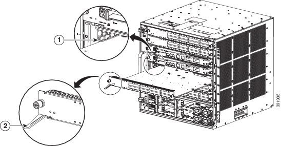
| Step 4 | Loosen the two captive screws on the module. Make sure that the two captive screws are completely unscrewed from the chassis. | ||
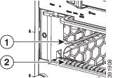
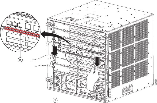
| Step 5 | Place your thumbs on the left and right ejector levers and simultaneously rotate the levers outward to unseat the module from the backplane connector. | ||
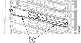
| Step 6 | Grasp the front edge of the module and slide the module part of the way out of the slot. Place your other hand under the module to support the weight of the module. Do not touch the module circuitry. | ||
| Step 7 | Place the removed module on an antistatic mat or in an antistatic bag, or immediately reinstall it in another slot. | ||
| Step 8 | Perform one of
the following steps:
If the slot is to remain empty and is adjacent to a module, you must install a module filler plate (Cisco part numbers SLOTBLANK-09 or WS-X6K-SLOT-CVR-E) to maintain proper air flow through the chassis. Do not install a blank slot cover (Cisco part number WS-X6K-SLOT-CVR) over the unused slot.
|
Installing Transceivers and Module Connectors
Some Ethernet modules require that pluggable transceivers be installed in the module port sockets. These transceivers are normally shipped separately from the module and must be installed after the module is installed in the chassis slot.
|
Transceiver or Module Connector Type |
Installation Procedure Document and Link |
|---|---|
|
SFP and SFP+ |
|
|
QSFP+ |
Attaching Network Interface Cables
Attaching Optical Network Interface Cables
Caution | Do not remove the plugs from the transceiver optical bores or the fiber-optic cable until you are ready to connect the cable. The plugs protect the transceiver optical bores and cable from contamination. |
| Step 1 | Remove the dust plugs from the network interface cable optical connectors. Save the dust plugs for future use. |
| Step 2 | Immediately
inspect and clean the optical connector's fiber-optic end-faces.
|
| Step 3 | Remove the dust
plugs from the transceiver optical bores.
If you are using the LX/LH GBIC with MMF, you need to install a patch cord between the GBIC and the MMF cable. The Read-Only WDM GBIC (WDM-GBIC-REC=) has only one optical bore (receive). |
| Step 4 | Immediately attach the network interface cable optical connector to the transceiver. Follow these guidelines: |
Mode-Conditioning Patch Cord
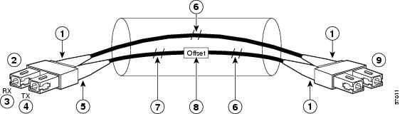
When using the long-wavelength and long-haul (LX and LH) GBIC with 62.5-micron diameter multimode fiber (MMF), you must install a mode-conditioning patch cord (Cisco product number CAB-GELX-625 or equivalent) between the GBIC and the MMF cable on both the transmit and receive ends of the link.
When an unconditioned laser source designed for operation on single-mode optical fiber (SMF) is directly coupled to an MMF cable, an effect known as differential mode delay (DMD) might result in a degradation of the modal bandwidth of the optical fiber cable. This degradation results in a decrease in the link span (the distance between a transmitter and a receiver) that can be supported reliably. The effect of DMD can be overcome by conditioning the launch characteristics of a laser source. A practical means of performing this conditioning is to use a device called a mode-conditioning patch cord.
A mode-conditioning patch cord is required for 1000BASE-LX and LH applications over FDDI-grade, OM1, and OM2 fiber-cable types. Mode-conditioning patch cords should not be used for applications over OM3 fiber cable (laser-optimized fiber cable). For more information about mode-conditioning patch cords, see the Use of Mode Conditioning Patch Cables in Gigabit Ethernet and 10 Gigabit Ethernet Laser-Based Transmissions bulletin available on Cisco.com.
|
1 |
Beige color identifier |
6 |
MMF |
|
2 |
To Gigabit Ethernet interface |
7 |
Single-mode fiber (SMF) |
|
3 |
RX (receiver) |
8 |
Offset junction |
|
4 |
TX (transmitter) |
9 |
To cable plant |
|
5 |
Blue color identifier |
 Note | We recommend that you use the LX and LH GBIC and MMF with the patch cord for short link distances of 33 to 328 feet (10 to 100 meters) because not using the patch could result in an elevated bit error rate (BER). |
The patch cord is required to comply with IEEE standards. IEEE found that link distances could not be met with certain types of fiber-optic cable due to a problem in the center of some fiber-optic cable cores. The solution is to launch light from the laser at a precise offset from the center by using the patch cord. At the output of the patch cord, the LX and LH GBIC complies with the IEEE 802.3z standard for 1000BASE-LX.
Installing the Patch Cord
Warning | Invisible laser radiation may be emitted from disconnected fibers or connectors. Do not stare into beams or view directly with optical instruments. Statement 1051 |
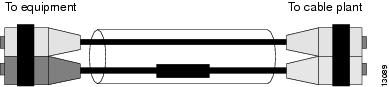
To install the patch cord, perform these steps:
1. Plug the end of the patch cord labeled To Equipment into the GBIC. See Figure 1.
2. Plug the end labeled To Cable Plant into the patch panel. See Figure 1.
DETAILED STEPS
Connecting Transceivers to a Copper Network
Caution | To comply with GR-1089 intrabuilding lightning immunity requirements, you must use grounded, shielded, twisted-pair Category 5 cabling. |
| Step 1 | Insert the
network cable RJ-45 connector into the RJ-45 connector on the transceiver.
When connecting to a 1000BASE-T-compatible switch or repeater, use four-twisted-pair, crossover Category 5 cabling. |
| Step 2 | Insert the other end of the network cable into an RJ-45 connector on a 1000BASE-T-compatible target device. |
Verifying the Installation
Verifying Newly Installed Modules
Enter the show module or show port [modnum/port_num] privileged EXEC command.
This verifies that the system acknowledges the new modules and has brought them online.
Enter the ping host user EXEC command to ping a host and check connectivity.
If the host is unresponsive, check the IP address of the switch and default IP route, if appropriate.
Example: show module Command Output for C6800-48P-TX-XL
These are examples of the show module command output for the C6800-48P-TX-XL Ethernet module:
Switch# show module sw 1
 Switch Number:     1   Role:  Virtual Switch Standby
----------------------  -----------------------------
Mod Ports Card Type                              Model              Serial No.
--- ----- -------------------------------------- ------------------ -----------
  1   20  DCEF2T 4 port 40GE / 16 port 10GE      WS-X6904-40G       SAL1624E826
  2    4  WiSM 2 WLAN Service Module             WS-SVC-WISM2-K9    SAL1523FLRV
  3    5  Supervisor Engine 2T 10GE w/ CTS (CSSO VS-SUP2T-10G       SAL17152F6Q
  4    5  Supervisor Engine 2T 10GE w/ CTS (Hot) VS-SUP2T-10G       SAL17152F7C
  5    4  Network Analysis Module 3              WS-SVC-NAM-3-K9    SAL16127XFD
  6   48  DCEF-XL 48P 10/100/1000MB Ethernet     C6800-48P-TX-XL    SAL1736CC7W

Mod MAC addresses                       Hw    Fw           Sw           Status
--- ---------------------------------- ------ ------------ ------------ -------
  1  1cdf.0f9b.df26 to 1cdf.0f9b.df39   1.0   12.2(50r)SYL 15.1(2)SY2   Ok
  2  e05f.b994.2660 to e05f.b994.266f   1.0   12.2(18r)S1  15.1(2)SY2   Ok
  3  2c54.2dc4.a0a5 to 2c54.2dc4.a0ac   1.5   12.2(50r)SYS 15.1(2)SY2   Ok
  4  2c54.2dc3.7499 to 2c54.2dc3.74a0   1.5   12.2(50r)SYS 15.1(2)SY2   Ok
  5  1cdf.0f9b.a76e to 1cdf.0f9b.a77d   1.1   12.2(50r)SYL 15.1(2)SY2   Ok
  6  7c69.f69b.c8d8 to 7c69.f69b.c907   0.1   12.2(18r)S1  15.1(2)SY2   Ok

Mod  Sub-Module                  Model              Serial       Hw     Status
---- --------------------------- ------------------ ----------- ------- -------
  1  Distributed Forwarding Card WS-F6K-DFC4-EXL    SAL1532M1VE  1.0    Ok
  3  Policy Feature Card 4       VS-F6K-PFC4XL      SAD1422005E  0.509  Ok
  3  CPU Daughterboard           VS-F6K-MSFC5       SAL17142D69  2.0    Ok
  4  Policy Feature Card 4       VS-F6K-PFC4XL      SAD142502KP  0.509  Ok
  4  CPU Daughterboard           VS-F6K-MSFC5       SAL171424F1  2.0    Ok
 5/0 NAM Application Processor   SVC-APP-PROC-1     SAL161065NJ  1.0    Ok
  6  Distributed Forwarding Card WS-F6K-DFC4-AXL    SAL1736CC7W  0.1    Ok

Base PID:
Mod  Model         Serial No.
---- -----------   ----------
  5 WS-SVC-APP-HW-1    SAL16127XFD

Mod  Online Diag Status
---- -------------------
  1  Pass
  2  Pass
  3  Pass
  4  Pass
  5  Not Applicable
 5/0 Not Applicable
  6  Pass
Switch#show module switch 1 slot 6

 Switch Number:     1   Role:  Virtual Switch Standby
----------------------  -----------------------------
Mod Ports Card Type                              Model              Serial No.
--- ----- -------------------------------------- ------------------ -----------
  6   48  DCEF-XL 48P 10/100/1000MB Ethernet     C6800-48P-TX-XL    SAL1736CC7W

Mod MAC addresses                       Hw    Fw           Sw           Status
--- ---------------------------------- ------ ------------ ------------ -------
  6  7c69.f69b.c8d8 to 7c69.f69b.c907   0.1   12.2(18r)S1  15.1(2)SY2   Ok

Mod  Sub-Module                  Model              Serial       Hw     Status
---- --------------------------- ------------------ ----------- ------- -------
  6  Distributed Forwarding Card WS-F6K-DFC4-AXL    SAL1736CC7W  0.1    Ok

Mod  Online Diag Status
---- -------------------
  6  Pass
Example: show module Command Output for C6800-48P-SFP
These are examples of the show module command output for the C6800-48P-SFP Ethernet module:
Switch# show module sw 2
 Switch Number:     2   Role:   Virtual Switch Active
----------------------  -----------------------------
Mod Ports Card Type                              Model              Serial No.
--- ----- -------------------------------------- ------------------ -----------
  1   20  DCEF2T 4 port 40GE / 16 port 10GE      WS-X6904-40G       SAL1627FUGE
  3    5  Supervisor Engine 2T 10GE w/ CTS (Acti VS-SUP2T-10G       SAL17152N0N
  4    5  Supervisor Engine 2T 10GE w/ CTS (CSSO VS-SUP2T-10G       SAL17152F4G
  7   48  DCEF 48P 1GE SFP                       C6800-48P-SFP      SAL1810N5E2

Mod MAC addresses                       Hw    Fw           Sw           Status
--- ---------------------------------- ------ ------------ ------------ -------
  1  1cdf.0f9b.e9fa to 1cdf.0f9b.ea0d   1.0   12.2(50r)SYL 15.1(2)SY2   Ok
  3  5057.a8e2.5e85 to 5057.a8e2.5e8c   1.5   12.2(50r)SYS 15.1(2)SY2   Ok
  4  5057.a8e2.5e4e to 5057.a8e2.5e55   1.5   12.2(50r)SYS 15.1(2)SY2   Ok
  7  b838.61d7.fca8 to b838.61d7.fcd7   0.1   12.2(18r)S1  15.1(2)SY2   Ok

Mod  Sub-Module                  Model              Serial       Hw     Status
---- --------------------------- ------------------ ----------- ------- -------
  1  Distributed Forwarding Card WS-F6K-DFC4-EXL    SAL1535P0LR  1.0    Ok
  3  Policy Feature Card 4       VS-F6K-PFC4XL      SAD1352022C  0.509  Ok
  3  CPU Daughterboard           VS-F6K-MSFC5       SAL17152L07  2.0    Ok
  4  Policy Feature Card 4       VS-F6K-PFC4XL      SAD140801W1  0.509  Ok
  4  CPU Daughterboard           VS-F6K-MSFC5       SAL17152KZK  2.0    Ok
  7  Distributed Forwarding Card WS-F6K-DFC4-A      SAL1810N5AL  2.0    Ok

Mod  Online Diag Status
---- -------------------
  1  Pass
  3  Pass
  4  Pass
  7  Pass
Switch# show module switch 2 slot 7
 Switch Number:     2   Role:   Virtual Switch Active
----------------------  -----------------------------
Mod Ports Card Type                              Model              Serial No.
--- ----- -------------------------------------- ------------------ -----------
  7   48  DCEF 48P 1GE SFP                       C6800-48P-SFP      SAL1810N5E2

Mod MAC addresses                       Hw    Fw           Sw           Status
--- ---------------------------------- ------ ------------ ------------ -------
  7  b838.61d7.fca8 to b838.61d7.fcd7   0.1   12.2(18r)S1  15.1(2)SY2   Ok

Mod  Sub-Module                  Model              Serial       Hw     Status
---- --------------------------- ------------------ ----------- ------- -------
  7  Distributed Forwarding Card WS-F6K-DFC4-A      SAL1810N5AL  2.0    Ok

Mod  Online Diag Status
---- -------------------
  7  Pass
 Feedback