Catalyst 6800 Ethernet Module Installation Guide
Bias-Free Language
The documentation set for this product strives to use bias-free language. For the purposes of this documentation set, bias-free is defined as language that does not imply discrimination based on age, disability, gender, racial identity, ethnic identity, sexual orientation, socioeconomic status, and intersectionality. Exceptions may be present in the documentation due to language that is hardcoded in the user interfaces of the product software, language used based on RFP documentation, or language that is used by a referenced third-party product. Learn more about how Cisco is using Inclusive Language.
- Updated:
- December 22, 2014
Chapter: Pluggable Transceivers, Module Connectors
Pluggable
Transceivers, Module Connectors
Pluggable Transceivers
This section provides brief descriptions of the pluggable transceivers that can be installed in the switch modules and supervisor engines. The following safety warnings apply:
 Warning | Only trained and qualified personnel should be allowed to install, replace, or service this equipment. Statement 1030 |
Warning | Ultimate disposal of this product should be handled according to all national laws and regulations. Statement 1040 |
Warning | Class I (CDRH) and Class 1M (IEC) laser products. Statement 1055 |
Warning | Use of controls, adjustments, or performing procedures other than those specified may result in hazardous radiation exposure. Statement 1057 |
1-GB Transceivers
|
1-GB Transceiver Type |
Supported on These Modules |
More Information |
|---|---|---|
|
SFP |
|
Cisco Small Form-Factor Pluggable Modules for Gigabit Ethernet Applications Data Sheet |
 Note | To determine if a specific SFP transceiver is compatible with the supported modules, see the Cisco Gigabit Ethernet Transceiver Modules Compatibility Matrix document that is available on Cisco.com. |
10-GB Transceivers
The switch supports 10-GB SFP+ transceivers. The following table lists the modules that the transceivers support and the links that provide transceiver specifications:
|
10-GB Transceiver Type |
Supported on These Modules |
More Information |
|---|---|---|
|
SFP+ transceivers |
|
|
To determine if a specific 10-GB transceiver is compatible with the supported modules, see the 10-Gigabit Ethernet Transceiver Modules Compatibility Matrix document that is available on Cisco.com.
40-GB Transceivers
The switch supports Quad Small Form-Factor Pluggable (QSFP) transceiver modules. The following table lists the modules that the transceivers support and the links that provide transceiver specifications:
|
40-GB Transceiver Type |
Supported on These Modules |
More Information |
|---|---|---|
|
QSFP Transceivers |
|
Note | To determine if a specific 40-GB transceiver is compatible with the supported modules, see the Cisco 40-Gigabit Ethernet Transceiver Modules Compatibility Matrix document that is available on Cisco.com. |
WDM Transceivers
The following table lists the supported modules, applicable illustrations, and the specification tables for WDM transceivers.
|
WDM Transceiver Type |
Description |
Supported on These Modules |
More Information |
||
|---|---|---|---|---|---|
|
CWDM SFP |
The Coarse Wavelength Division Multiplexing (CWDM) SFP is a hot-swappable device that you can plug into SFP-compatible modules and supervisor engines. The CWDM SFP transceiver uses an LC optical connector to connect to a single-mode fiber-optic (SMF) cable. You can connect the CWDM SFPs to the CWDM passive optical system optical add/drop multiplexer (OADM) modules or multiplexer/demultiplexer plug-in modules using single-mode fiber-optic cables. |
|
|||
|
DWDM SFP |
The Cisco DWDM SFP is a hot-swappable I/O transceiver module that you can plug into Gigabit Ethernet SFP ports or slots. It supports the ITU 100-GHz wavelength grid and matches the wavelength plan for the Cisco 100-GHz ONS product family. It is a fixed-wavelength SFP, with 40 different SFP models. It uses standard SFP interface network: dual LC/PC connector.
|
|
Cisco Dense Wavelength-Division Multiplexing Small Form-Factor Pluggable Module |
||
|
DWDM SFP+ |
The Cisco DWDM SFP+ transceiver module is a hot-swappable I/O device that you can plug into an Ethernet SFP+ port of a Cisco switch or router to link the port with the network. It supports 40 nontunable ITU 100-GHz wavelengths. It also supports digital optical monitoring capability and the Cisco quality identification (ID) feature, which enables a Cisco switch or router to identify whether or not the module is an SFP+ module certified and tested by Cisco. |
|
Note | To determine if a specific WDM transceiver is compatible with the supported modules, see the Cisco Gigabit Ethernet Transceiver Modules Compatibility Matrix document that is available on Cisco.com. |
Module Connectors
This section provides brief descriptions of the module connectors that the switch supports.
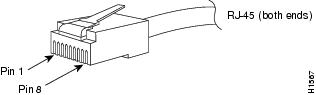
RJ-45 Connector
The RJ-45 connector is used to connect a Category 3, Category 5, Category 5e, or Category 6 foil twisted-pair or unshielded twisted-pair cable from the external network to the module interface connector.
 Caution | Category 5e, Category 6, and Category 6a cables can store large levels of static electricity because of the dielectric properties of the materials used in their construction. Always ground the cables (especially in new cable runs) to a suitable and safe earth ground before connecting them to the module. |
Caution | To comply with GR-1089 intrabuilding and lightning immunity requirements, you must use a foil twisted-pair (FTP) cable that is properly grounded at both ends. |
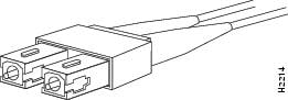
SC Connector
The SC connector is used to connect fiber-optic module ports or transceivers with the external SMF or MMF network.
Warning | Invisible laser radiation may be emitted from disconnected fibers or connectors. Do not stare into beams or view directly with optical instruments. Statement 1051 |
Note | Make sure that the optical connectors are clean before making the connections. Contaminated connectors can damage the fiber and cause data errors. |
Always insert the network connector completely into the socket. A secure connection is especially important when you are establishing a connection between a module and a long-distance (1.24 miles) (2 km) network, or a module and a suspected highly attenuated network. If the link LED does not light up, try removing the network cable plug and reinserting it firmly into the module socket. It is possible that dirt or skin oils have accumulated on the plug faceplate (around the optical-fiber openings), generating significant attenuation and reducing the optical power levels below threshold levels so that a link cannot be established.
Caution | Use extreme care when removing or installing connectors so that you do not damage the connector housing or scratch the end-face surface of the fiber. Always install protective covers on unused or disconnected components to prevent contamination. Always clean fiber connectors before installing them. |
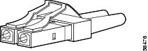
LC Connector
The LC fiber optic connector is a small form-factor fiber-optic connector that provides high-density fiber connectivity. The LC connector can be used with either MMF cable or SMF cable. The LC connector uses a latching clip mechanism that is similar to the one used on the RJ-45 copper connector.
Warning | Invisible laser radiation may be emitted from disconnected fibers or connectors. Do not stare into beams or view directly with optical instruments. Statement 1051 |
Note | Make sure that the optical connectors are clean before making the connections. Contaminated connectors can damage the fiber and cause data errors. |
 Feedback