- Preface
- New and Changed Information
- Overview
- Configuring Ethernet Interfaces
- Configuring VLANs
- Configuring Private VLANs
- Configuring Rapid PVST+
- Configuring Multiple Spanning Tree
- Configuring STP Extensions
- Configuring LLDP
- Configuring MAC Address Tables
- Configuring IGMP Snooping
- Configuring MVR
- Configuring VTP V3
- Configuring Traffic Storm Control
- Configuring the Fabric Extender
- Configuring VM-FEX
- Configuring MAC/ARP Hardware Resource Carving Template
- Configuring VN-Segment
- Configuring VXLANs
Configuring VXLANs
This chapter contains the following sections:
- Information About VXLAN
- Guidelines and Limitations for VXLAN
- Enabling VXLAN
- Configuring a VNI
- Configuring a Network Virtualization Endpoint Interface
- Configuring a Switch in the Store-and-Forward Mode
- Disabling VXLAN
- Verifying VXLAN Configuration
- Example of VXLAN Bridging Configuration
Information About VXLAN
You can use Virtual Extensible Local Area Networks (VXLANs) to extend reachability of a VLAN within a data center over Layer 3. When you use VXLANs, you are no longer restricted to using only 4096 VLANs in a data center.
A Layer 2 VLAN is mapped into a larger (24-bit) ID VXLAN Network Identifier (VNI). All frames on that VLAN are encapsulated in an IP/UDP frame for transport. An additional VXLAN header is added to carry the VNI information. The VNI identifies the Layer 2 segment that the frame belongs to and is used to define a much larger Layer 2 broadcast domain for that frame. Typically, a Layer 2 domain (VLAN) confines the VM's mobility. With a VXLAN, the Layer 2 domain is extended throughout the data center, increasing the VM's mobility by extending the Layer 2 broadcast domain across Layer 3. The 24-bit VNI provides for about 16 million different Layer 2 segments that support a large number of tenants, and their VLANs, in a multitenant data center.
VXLAN Layer 2 Gateway
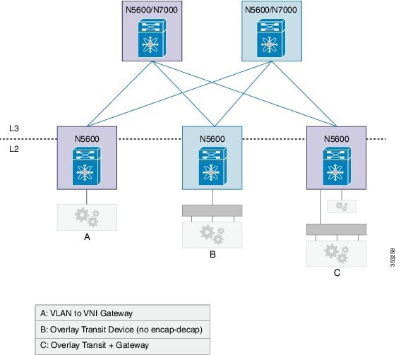
A VXLAN gateway is a device that encapsulates a classical Ethernet (CE) frame into a VXLAN frame and decapsulates a VXLAN frame into a CE frame. A gateway device transparently provides VXLAN benefits to the physical hosts and virtual machines. The physical hosts or VMs are completely unaware of VXLAN encapsulation. The gateway function can be implemented in a physical network device such as the Cisco Nexus 5600 Series Switch or a vSwitch such as the Cisco Nexus 1000V.
VXLAN Router
Similar to traditional routing between different VLANs, a VXLAN router is required for communication between devices that are in different VXLAN segments. The VXLAN router translates frames from one VNI to another. Depending on the source and destination, this process might require decapsulation and reencapsulation of a frame. The Cisco Nexus device supports all combinations of decapsulation, route, and encapsulation. The routing can also be done across native Layer 3 interfaces and VXLAN segments.
You can enable VXLAN routing at the aggregation layer or on Cisco Nexus device aggregation nodes. The spine only forwards based IP and ignores the encapsulated packets. To help scaling, a few leaf nodes (a pair of border leaves) perform routing between VNIs. A set of VNIs can be grouped into a virtual routing and forwarding (VRF) instance (tenant VRF) to enable routing among those VNIs. If routing must be enabled among a large number of VNIs, you might need to split the VNIs between several VXLAN routers. Each router is responsible for a set of VNIs and a respective subnet. Redundancy is achieved with FHRP.
The following figure shows a configuration example with two Cisco Nexus leaf nodes (each node is a virtual port channel [vPC] pair) that acts as VXLAN routers. Node A routes VNIs 1 to 100 while node B routes VNIs 201 to 300. You must configure a separate VNI (555) per tenant VRF to carry traffic between VXLAN routers and for routing protocols to exchange routing information between the VXLAN routers.
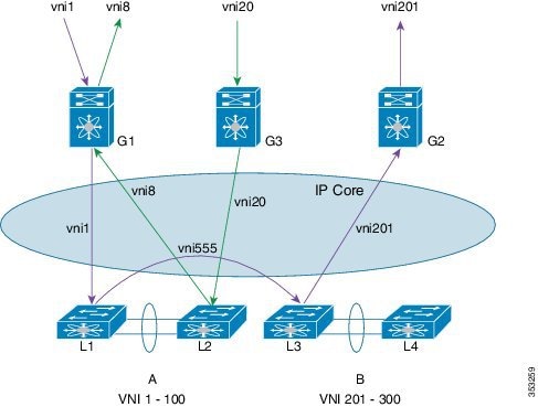
The figure shows two flows. vni-1 to vni-201 and vni-20 to vni-8.
-
vni-1 to vni-201 : The packet in vNI1 at G1 is sent to the default router for vni-1 (L1 and L2). The router finds that the destination address is in vni-201 which is reachable over interface vni-555. The packet is encapsulated with vni-555 and sent to the L3 and L4 pair. The router pair (L3 and L4) routes the packet from vni-555 to vni-201 where the final destination is reachable. The packet is then sent to G2, which uses vni-201 to be delivered to the final destination. This packet takes two router hops.
-
vni-20 to > vni-8: The packet at G3 in vni-20 is sent to the default router (L1 and L2). The final destination is reachable on vni-8. Router (L1 and L2) reencapsulates the packet with vni-8 and sends it to G1 where the final destination resides.
Any packet that originates in vni 1 to 100, but is destined to go outside of its VNI, must come to node A to get routed. Similarly, any packet delivered to vni 201 to 300 whose source is different from the destination VNI is routed into its destination VNI on node B. Packets from vni-1 to vni-201 take two hops (the first hop on node A and the second on node B).
The traffic that is routed between a VNI and outside (nonvirtualized) world might have to go through an external router that is connected to the VXLAN router. This router might need to provide Network Address Translation (NAT) and firewall services as well.
The VXLAN routers can use any routing protocol, for example Open Shortest Path First (OSPF), for routing within the tenant VRF. The routers must form neighbor adjacencies over the transit-VNI, because the tenant VRFs are not visible in the core. The core routers only know about the underlay VRF that is used for routing the packets between VXLAN Tunnel Endpoints (VTEPs) that are based on the outer header.
VXLAN Overlay Network for Broadcast/Unknown-Unicast/Multicast Overlay Traffic
All broadcast/unknown-unicast/multicast overlay traffic must be sent to multiple VTEPs. To identify all the VTEPs that are interested in traffic for a specific VNI, VTEPs build a multicast tree which is identified as the VXLAN Overlay Network for each VNI. This is achieved by mapping the VNI to a multicast group on all the VTEPs that are interested in the VNI. A multicast tree is built using the PIM protocol and all non-unicast traffic is distributed to all the interested VTEPs that join the multicast tree. This is achieved by mapping any given VNI to a multicast group address, which is also called the Delivery Group (DG) for that VNI. When VTEP sends a non-unicast packet on a VNI over the overlay network, the packet is encapsulated in a VXLAN header and is sent to the DG address instead of sending it to single destination VTEP IP address as in the case of unicast traffic. The VXLAN encapsulated packets destined to the DG get routed in the overlay network by using the PIM tree built for the DG . All the VTEPs that join the PIM tree built for that DG receive the traffic.
Cisco Nexus devices use PIM BIDIR only to build this VXLAN Overlay Network. PIM ASM/SSM is not supported currently, so any multicast group defined as DG to carry VXLAN overlay traffic for a VNI must always be defined as a BIDIR group. The rendezvous point (RP) for this BIDIR group can be anywhere in the Layer 3 overlay network. Multiple VNIs can map to the same DG, and so the overlay traffic for these VNIs is sent across the Overlay Network using the same PIM BIDIR tree. Cisco Nexus devices can support a maximum of 200 DGs on a given VTEP.
VXLAN Multicast Routing
You can configure the VXLAN router as a multicast router for inner (user) multicast groups. Multicast routing must be configured within a tenant VRF. The multicast routing protocol for the inner groups does not have to be PIM BIDIR even though PIM BIDIR is used for the outer multicast. The inner multicast group can use PIM-Any Source Multicast (ASM), ASM, or BIDIR as supported by the platform. If VTEP is a part of a vPC pair, the inner group cannot be a BIDIR group. In a vPC setup, BIDIR can be used only as a DG to build the VXLAN overlay network and cannot be used to carry inner multicast traffic. Similar to VXLAN unicast routing, multicast routing is done among the VNI interfaces that are in a tenant VRF. The VXLAN gateway nodes deliver the multicast data and control frames to the VXLAN multicast router using an outer delivery group (DG).
PIM routers for the inner multicast group exchange the PIM messages over a VXLAN network that connects them on all VNIs that are part of the tenant VRF.
- Cisco Nexus Device Overlays
- VXLAN Tunnel Endpoint
- VXLAN Tunnel Endpoint Peers
- vPC Considerations
- QoS/ACL Support
- TTL Handling
- Multipathing Support
- MTU
Cisco Nexus Device Overlays
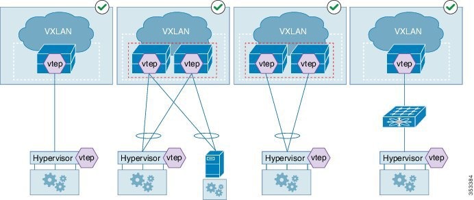
The following figure shows a topology with a virtual port channel (vPC), fabric extenders (FEXes), VXLAN hypervisors, and gateway ports that are supported by the Cisco Nexus device. All FEX topologies (AA-FEX, ST-FEX, and 2LvPC) are supported.
The figure below shows the supported topologies. A VXLAN Tunnel Endpoint (VTEP) hypervisor can be connected through switch vPC as shown in diagrams 2 and 3. Diagram 4 shows that the hypervisor can be connected through Straight-through (ST) FEX (without vPC).
The figure below shows the unsupported topologies. A VXLAN Tunnel Endpoint (VTEP) hypervisor cannot be connected through FEX vPC configurations—ST-FEX vPC, AA-FEX, and 2LVPC, as shown in the first three diagrams. Diagram 4 shows that mixing of overlay and non-overlay devices is not supported on the same fabric extender (FEX).

VXLAN Tunnel Endpoint
A VXLAN Tunnel Endpoint (VTEP) performs the VXLAN gateway function. A VTEP is represented as an interface in the Cisco NX-OS. All VTEPs are managed by the VXLAN manager. The Cisco Nexus device requires one VTEP for each encapsulation type.
VTEP IP Addresses and VRF Instances
Each VTEP must have at least one IP address. This IP address is used for encapsulation or decapsulation. For vPC configurations, a separate IP address is used for encapsulation or decapsulation of the traffic to and from vPC connected hosts. The emulated IP address must be the same on both switches in a vPC pair. The emulated IP address allows the network to load balance the traffic destined to the vPC-connected devices without using MCT. Similarly, a distinct non-emulated IP address that is used for encapsulation or decapsulation for a singly connected host ensures that traffic to that host arrives on the correct switch in the pair without going through a vPC Peer-Link, also known as Multichassis EtherChannel Trunk (MCT).
The VRF instance specified for the VTEP carries all the encapsulated traffic within the data center.
The Cisco Nexus device supports a single infrastructure (infra)-VRF and multiple tenant VRFs. The infra-VRF carries the VXLAN traffic through the core Layer 3 network. A tenant VRF is not visible to the routing devices in the core. The tenant VRFs are used by VXLAN routers. The Cisco Nexus device supports the default VRF as the infra-VRF.
VTEP IP Multicast Addresses
A VXLAN gateway uses an IP delivery group (DG) to flood multidestination frames within a VNI. Layer 2 broadcast, unknown unicast, and multicast frames are flooded to other VTEPs using the IP multicast DG address. Only one flood-DG address can be used per VNI. To reduce the amount of BUM traffic that reaches all VTEPs, each VNI should be given its own DG address so that the flood domain is contained within the VTEPs that are a gateway for the VNI. The number of VNIs might exceed the distinct DG trees that can be supported by the network. In that case, multiple VNIs must share a DG address for flooding. The user (inner or overlay) multicast frames are also encapsulated using a DG.
VXLAN Tunnel Endpoint Peers
VTEP-Peer Learning
The Cisco Nexus device discovers VXLAN Tunnel Endpoint Peers (VTEPs) using the flood-and-learn technique which is when a VTEP peer is learned when the first VXLAN encapsulated packet is received from the peer.
A gateway device must identify only those VTEP peers that support any of the locally configured VNIs or delivery groups (DG).
The Cisco Nexus device has the capability to snoop unicast, as well as, multicast packets sent by unknown peers. If an unknown VTEP-peer sends packets using any of the multicast DGs configured locally, a notification is received from the hardware, which provides the information about the new peer. In addition to monitoring the multicast DG addresses, the Cisco Nexus device also monitors frames sent to its own VTEP addresses. The multicast and unicast frames snooped by the hardware are not de-capsulated until the sender is a known VTEP-peer.
The VXLAN manager adds the sender VTEP as a new peer. After the VTEP peer is added in the hardware, the hardware would then stop sending the VTEP peer discovery notification for it.
Due to the sharing of DG addresses, the VNI in the packet might not be configured as a gateway VNI. In that case, the VTEP peer avoids further VTEP peer discovery indications.
VTEP-Peer Aging/Removal
A VTEP-peer might shut down, be removed from the network, become unreachable, or just become dormant. In many situations, there is no direct indication to remove the VTEP-peer. Therefore, you must employ an aging mechanism to clean up the VTEP peers that were dynamically learned. The cleanup is essential because the total number of active VTEP peers present at any given time is limited by the hardware. The ageout time is set to 10 minutes.
vPC Considerations
vPC Consistency Checks
|
Parameter |
vPC Check Type |
Description |
|---|---|---|
|
VLAN-VNI mapping |
Type-1—nongraceful |
Brings down the affected VLANs on vPC ports on both sides. |
|
VTEP-Member-VNI |
Type-1—nongraceful |
Member VNIs must be the same on both nodes. VNIs that are not common bring down the corresponding VLANs on vPC ports on both sides. |
|
VTEP-emulated IP |
Type-1—graceful |
If an emulated IP address is not the same on both nodes, all gateway vPC ports on one side (secondary) are brought down. Alternatively, one side of all vPC ports is brought down. |
|
VTEP-node IP address |
Type 2 |
vPC manager issues a warning. |
vPC and Multicast
For each outer destination group (DG), you must select one of the vPC peers as a designated Affinity Forwarder (AF). The AF switch forwards the multidestination traffic to the vPC connected devices while a non-AF switch only forwards traffic to singly connected devices. The selection of an AF is done by a multicast group that is based on a vPC permanent role.
QoS/ACL Support
Quality of Service (QoS) and Access Control Lists (ACLs) are applied to the ingress packets for packets from VLAN to VXLAN (encapsulation). During encapsulation, the outer Class of Service (CoS) and differentiated services code point (DSCP) values are derived from the final inner COS and DSCP values. When a packet is decapsulated, the outer CoS is used as the inner CoS, because there is no inner .1Q, or .1P tag carried with the inner frame. The rest of the processing is done on the inner frame.
If traffic is decapsulated and reencapsulated, the inner CoS value is used to derive the outer DSCP value. The CoS is preserved from the ingress frame.
For overlay transit traffic (traffic that is not decapsulated), QoS and ACLs are applied to the outer headers.
TTL Handling
When a native classical Ethernet (CE) packet is encapsulated, the outer Time To Live (TTL) is selected based on a configured value. The default is 32. The outer TTL is decremented based on the outer IP routing and discarded when it goes to zero. The inner TTL is unchanged as the packet traverses the overlay network. After decapsulation, the inner TTL is preserved if the inner packet is Layer 2 switched. The inner TTL is decremented whenever an inner packet is routed.
When a multicast packet is decapsulated and reencapsulated, the outer TTL is decremented by 1 while the inner TTL is preserved. If the inner packet is multicast routed, the inner TTL is decremented whenever an unencapsulated inner packet is delivered to the end station.
Multipathing Support
When a CE packet is encapsulated using VXLAN encapsulation, a 16-bit hash value is created using the Layer 2 and Layer 3 addresses and Layer 4 source and destination ports if available. The hash value is then used as an outer UDP src_port. This hash value represents the inner-packet flow (with some aliasing due to the 16-bit hash result). The outer UDP source port is used by core routers to load balance traffic between two VTEPs based on inner flows.
When the packet is first encapsulated, inner packet headers are used to select one of many available equal cost paths to the destination VTEP.
MTU
The Cisco Nexus device does not support fragmentation or re-assembly of VXLAN traffic. As VXLAN encapsulation adds 50 bytes to the packet, the MTU of the tenant devices must be at least 50 bytes smaller than the MTU of the network devices. The Cisco VXLAN device supports an MTU configuration on a physical interface as well as an SVI interface. Ensure that the MTU on the VNI-mapped SVI is 50 bytes smaller than the physical interfaces's MTU when configuring VXLAN routing. For a VXLAN Layer 2 gateway, the default MTU is 1500. The recommended method is to increase the MTU to 1550.
Guidelines and Limitations for VXLAN
The VXLAN configuration guidelines and limitations are as follows:
-
A VXLAN device must be configured in the store-and-forward mode.
-
The classical Ethernet (CE) packet on an edge interface is mapped to a VNI based on the VLAN to which it is associated. The VLAN to Virtual Network Identifier (VNI) mapping is created under the VLAN configuration, which limits the number of supported VNIs on a switch to 4000.
-
The multicast delivery group used to build the VXLAN overlay network for VNIs must be configured as a Protocol-Independent Multicast (PIM) Bidirectional (BIDIR) group. The VXLAN overlay network cannot be built using PIM SM or PIM SSM.
-
PIM-BDIR in a vPC configuration for non-VXLAN traffic is not supported.
-
The Cisco Nexus device does not support Layer 3 links on southbound interfaces that are connected to a fabric extender (FEX).
-
Only loopback interfaces are supported as the source interface for the NVE interface. under an Network Virtualization Edge (NVE) configuration. NVE is equal to VTEP.
-
For any protocols that work over inner switched virtual interfaces (SVIs), you should increase the maximum transmission unit (MTU) of that SVI by 50 to allow VXLAN encapsulation. If you use the default MTU, you might get unexpected results.
-
A VXLAN Tunnel Endpoint (VTEP) hypervisor cannot be connected through Straight-Through FEX (ST-FEX-VPC), Active-Active FEX (AA-FEX), and 2-Layer vPC.
-
The Cisco Nexus device can only support Layer 3 routed port links to carry overlay traffic to the core.
-
A Layer 2 trunk cannot be used to carry overlay traffic to the core. Layer 2 trunks with SVIs can be used on southbound interfaces that connect to hypervisors. The overlay traffic that originates to and from hypervisors is carried using an SVI.
-
The IP routing protocol must be configured for the underlay network.
-
PIM-BIDIR multicast routing must be configured for the underlay network.
-
The vn-segment-vlan-based feature must be configured on the VXLAN gateway and router devices.
-
IGMP snooping is not supported on VXLAN VLANs.
-
Hypervisor VTEPs (such as Cisco Nexus 1000V) cannot be connected using Layer 3 interfaces. They must be connected through Layer 2 interfaces.
-
Only one NVE interface is supported on a switch.
-
SNMP is not supported on the NVE interface.
-
Policy-based routing (PBR) is not supported for tenant traffic.
-
Ingress and egress ACLs cannot be applied to the outer header of the VXLAN packet on the VXLAN gateway device.
-
A physical port cannot be used as a tenant (gateway) port and overlay port at the same time.

Note
-
The maximum transmission unit (MTU) must configured throughout the network to accommodate 50 bytes of VXLAN encapsulation.
-
Tenant ports and overlay ports that connect to VTEP hypervisors cannot be on the same fabric extender (FEX).
-
When you are connecting VTEP hypervisors to FEX ports, all VTEP hypervisors that are connected to a FEX must use the same outer VLAN.
-
Refer to supported and un-supported topology diagrams when connecting hosts and VTEP hypervisors to a Cisco Nexus device.
-
Configured store and forward mode with reload.
-
Connecting hypervisors with different overlay encapsulation to the same FEX is not allowed.
-
VLAN 1 cannot be used to carry VXLAN traffic.
-
There is no support for originating Hot Standby Router Protocol (HSRP) packets with the source MAC as a user-configured HSRP MAC. Support is limited to using standard HSRP MAC addresses (v1 and v2) as the source MAC addresses for HSRP packets.
-
The show interface nve 1 counters command does not display statistics of VXLAN incoming and outgoing packets.
-
DHCP snooping on VXLAN-enabled VLANs is not supported.
vPC Considerations
-
A virtual IP must be configured for the vPC pair
-
A virtual IP must be configured for loopback purposes.
-
A peer-link switched virtual interfaces (SVI) must be only on a peer-link in external communication. A configuration example:
vpc nve peer-link-vlan 99
interface vlan99
no shutdown
no ip redirects
ip address 99.1.1.1/24
ip ospf cost 10
ip router ospf 1 area 0.0.0.0
ip pim sparse-mode
-
A special peer-link SVI must be configured on the VPC pair.
-
VPC peers must have identical configurations:
-
A VTEP hypervisor cannot be connected to AA-FEX, EVPC, or ST-FEX vPC.
-
Supports a line-rate encapsulation or decapsulation of VXLAN switched traffic.
Note
VXLAN introduces a 50-byte overhead to the original packet due to VXLAN encapsulation. For example, for a 1000 byte packet, there is a 5% overhead per packet. Overhead varies depending on the packet size and it is expected for VXLAN.
Enabling VXLAN
You must configure underlay and PIM-bidir multicast.
Configure the switch in the store-and-forward mode. See Configuring a Switch in the Store-and-Forward Mode.
This example shows how to enable VXLAN:
switch# configure terminal
switch(config)# feature nv overlay
switch(config)# feature vn-segment-vlan-based
Configuring a VNI
This example shows how to configure a VNI:
switch# configure terminal
switch(config)# vlan 1001
switch(config)# vn-segment 8000
Configuring a Network Virtualization Endpoint Interface
This examples shows how to configure a network virtualization interface:
switch# configure terminal
switch(config)# interface nve 1
switch(config-if-nve)# source interface loopback 0
switch(config-if-nve)# member vni 21000 mcast-group 239.3.5.1
switch(config-if-nve)# no shutdown
switch(config-if-nve)# copy running-config startup-config
Configuring a Switch in the Store-and-Forward Mode
This example shows how to configure a switch in the store-and-forward mode:
switch# configure terminal
switch(config)# hardware ethernet store-and-fwd-switching
switch(config)# copy running-config startup-config
Switch must now be reloaded.
Disabling VXLAN
This example shows how to disable a VXLAN:
switch# configure terminal
switch(config)# no feature nv overlay
switch(config)# no feature vn-segment-vlan-based
Verifying VXLAN Configuration
Use one of the following commands to verify the configuration:
|
Command |
Purpose |
|---|---|
|
switch# show interface nve id |
Displays details of the NVE interface. |
|
switch# show platform fwm info nve peer [all] |
Displays a list of NVE peers detected by using their IP address. |
|
switch# show mac address-table nve [count] [encap_type] |
Displays MAC addresses behind NVE peers. |
|
switch# show vlan counters |
Displays packet counters for a VLAN. |
|
switch# show nve peer |
Displays a list of discovered peers participating in the same VNIs. |
|
switch# show nve vni |
Displays a list of the configured VNIs. |
|
switch# show platform fwm info nve vni |
Displays a list of configured VNIs. |
|
switch# show nve conflict all |
Displays conflicts due to misconfiguration. |
|
switch# show run | grep "vpc nve" |
|
|
switch# show platform fwm info global | grep -i "NVE peer" |
|
Example of VXLAN Bridging Configuration
An example of loopback interface configuration and routing protocol configuration:
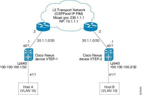
Cisco Nexus device VTEP-1 configuration:
switch-vtep-1(config)# feature ospf
switch-vtep-1(config)# feature pim
switch-vtep-1(config)# router ospf 1
switch-vtep-1(config-router)# router-id 100.100.100.1
switch-vtep-1(config)# ip pim rp-address 10.1.1.1 group-list 224.0.0.0/4 bidir
switch-vtep-1(config)# interface loopback0
switch-vtep-1(config-if)# ip address 100.100.100.1/32
switch-vtep-1(config-if)# ip router ospf 1 area 0.0.0.0
switch-vtep-1(config-if)# ip pim sparse-mode
switch-vtep-1(config)# interface e2/1
switch-vtep-1(config-if)# ip address 20.1.1.1/30
switch-vtep-1(config-if)# ip router ospf 1 area 0.0.0.0
switch-vtep-1(config-if)# ip pim sparse-mode
switch-vtep-1(config)# feature nv overlay
switch-vtep-1(config)# feature vn-segment-vlan-based
switch-vtep-1(config)# interface e1/1
switch-vtep-1(config-if)# switchport
switch-vtep-1(config-if)# switchport access vlan 10
switch-vtep-1(config-if)# no shutdown
switch-vtep-1(config)# interface nve1
switch-vtep-1(config-if)# no shutdown
switch-vtep-1(config-if)# source-interface loopback0

switch-vtep-1(config-if)# member vni 10000 mcast-group 230.1.1.1
switch-vtep-1(config)# vlan 10
switch-vtep-1(config-vlan)# vn-segment 10000
switch-vtep-1(config-vlan)# exit
Cisco Nexus device VTEP-2 configuration:
switch-vtep-2(config)# feature ospf
switch-vtep-2(config)# feature pim
switch-vtep-2(config)# router ospf 1
switch-vtep-2(config-router)# router-id 100.100.100.2
switch-vtep-2(config)# ip pim rp-address 10.1.1.1 group-list 224.0.0.0/4 bidir
switch-vtep-2(config)# interface loopback0
switch-vtep-2(config-if)# ip address 100.100.100.2/32
switch-vtep-2(config-if)# ip router ospf 1 area 0.0.0.0
switch-vtep-2(config-if)# ip pim sparse-mode
switch-vtep-2(config)# interface e2/1
switch-vtep-2(config-if)# ip address 30.1.1.1/30
switch-vtep-2(config-if)# ip router ospf 1 area 0.0.0.0
switch-vtep-2(config-if)# ip pim sparse-mode
switch-vtep-2(config)# feature nv overlay
switch-vtep-2(config)# feature vn-segment-vlan-based
switch-vtep-2(config)# interface e1/1
switch-vtep-2(config-if)# switchport
switch-vtep-2(config-if)# switchport access vlan 10
switch-vtep-2(config-if)# no shutdown
switch-vtep-2(config)# interface nve1
switch-vtep-2(config-if)# no shutdown
switch-vtep-2(config-if)# source-interface loopback0

switch-vtep-2(config-if)# member vni 10000 mcast-group 230.1.1.1
switch-vtep-2(config)# vlan 10
switch-vtep-2(config-vlan)# vn-segment 10000
switch-vtep-2(config-vlan)# exit
An example of the results of a VXLAN configuration:
switch(config)# show nve vni

Interface          VNI        Multicast-group   VNI State
----------------   --------   ---------------   ---------
nve1               10000      230.1.1.1          up

switch(config)# show nve peers

Interface          Peer-IP           VNI        Up Time
----------------   ---------------   --------   -----------
nve1               100.100.100.2     10000      06:13:07

switch(config)# show mac address-table

Legend:
        * - primary entry, G - Gateway MAC, (R) - Routed MAC, O - Overlay MAC
        age - seconds since last seen,+ - primary entry using vPC Peer-Link,
        (T) - True, (F) - False
   VLAN     MAC Address      Type      age     Secure NTFY Ports
---------+-----------------+--------+---------+------+----+------------------
*  100     0000.bb01.0001   dynamic  0         F      F    nve1
*  100     0000.bb01.0002   dynamic  0         F      F    nve1
*  100     0000.bb01.0003   dynamic  0         F      F    nve1
*  100     0000.bb01.0004   dynamic  0         F      F    nve1
*  100     0000.bb01.0005   dynamic  0         F      F    nve1
*  100     0000.bb01.0006   dynamic  0         F      F    nve1
For a vPC VTEP configuration, the loopback address requires a secondary IP.
An example of a vPC VTEP configuration:
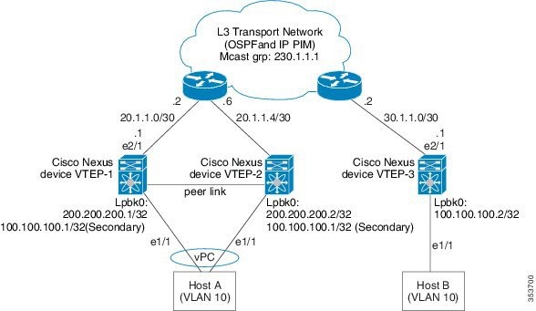
Cisco Nexus device VTEP-1 configuration:
switch-vtep-1(config)# feature nv overlay
switch-vtep-1(config)# feature vn-segment-vlan-based
switch-vtep-1(config)# feature ospf
switch-vtep-1(config)# feature pim
switch-vtep-1(config)# router ospf 1
switch-vtep-1(config-router)# router-id 200.200.200.1
switch-vtep-1(config)# ip pim rp-address 10.1.1.1 group-list 224.0.0.0/4 bidir
switch-vtep-1(config)# interface loopback0
switch-vtep-1(config-if)# ip address 200.200.200.1/32
switch-vtep-1(config-if)# ip address 100.100.100.1/32 secondary
switch-vtep-1(config-if)# ip router ospf 1 area 0.0.0.0
switch-vtep-1(config-if)# ip pim sparse-mode
switch-vtep-1(config)# interface e2/1
switch-vtep-1(config-if)# ip address 20.1.1.1/30
switch-vtep-1(config-if)# ip router ospf 1 area 0.0.0.0
switch-vtep-1(config-if)# ip pim sparse-mode
switch-vtep-1(config)# interface port-channel 10
switch-vtep-1(config-if)# vpc 10
switch-vtep-1(config-if)# switchport
switch-vtep-1(config-if)# switchport mode access
switch-vtep-1(config-if)# switchport access vlan 10
switch-vtep-1(config-if)# no shutdown
switch-vtep-1(config)# interface e1/1
switch-vtep-1(config)# channel-group 10 mode active
switch-vtep-1(config-if)# no shutdown
switch-vtep-1(config-if)# interface nve1
switch-vtep-1(config-if)# no shutdown
switch-vtep-1(config-if)# source-interface loopback0

switch-vtep-1(config-if)# member vni 10000 mcast-group 230.1.1.1
switch-vtep-1(config)# vlan 10
switch-vtep-1(config-vlan)# vn-segment 10000
switch-vtep-1(config-vlan)# exit

switch-vtep-1(config)#vpc nve peer-link-vlan 99
interface Vlan99
  no shutdown
  no ip redirects
  ip address 99.1.1.1/24
  ip ospf cost 10
  ip router ospf 1 area 0.0.0.0
  ip pim sparse-mode
Cisco Nexus device VTEP-2 configuration:
switch-vtep-2(config)# feature nv overlay
switch-vtep-2(config)# feature vn-segment-vlan-based
switch-vtep-2(config)# feature ospf
switch-vtep-2(config)# feature pim
switch-vtep-2(config)# router ospf 1
switch-vtep-2(config-router)# router-id 200.200.200.2
switch-vtep-2(config)# ip pim rp-address 10.1.1.1 group-list 224.0.0.0/4 bidir
switch-vtep-2(config)# interface loopback0
switch-vtep-2(config-if)# ip address 200.200.200.2/32
switch-vtep-2(config-if)# ip address 100.100.100.1/32 secondary
switch-vtep-2(config-if)# ip router ospf 1 area 0.0.0.0
switch-vtep-2(config-if)# ip pim sparse-mode
switch-vtep-2(config)# interface e2/1
switch-vtep-2(config-if)# ip address 20.1.1.5/30
switch-vtep-2(config-if)# ip router ospf 1 area 0.0.0.0
switch-vtep-2(config-if)# ip pim sparse-mode
switch-vtep-2(config)# interface port-channel 10
switch-vtep-2(config-if)# vpc 10
switch-vtep-2(config-if)# switchport
switch-vtep-2(config-if)# switchport mode access
switch-vtep-2(config-if)# switchport access vlan 10
switch-vtep-2(config-if)# no shutdown
switch-vtep-2(config)# interface e1/1
switch-vtep-2(config)# channel-group 10 mode active
switch-vtep-2(config-if)# no shutdown
switch-vtep-2(config-if)# interface nve1
switch-vtep-2(config-if)# no shutdown
switch-vtep-2(config-if)# source-interface loopback0

switch-vtep-2(config-if)# member vni 10000 mcast-group 230.1.1.1
switch-vtep-2(config)# vlan 10
switch-vtep-2(config-vlan)# vn-segment 10000
switch-vtep-2(config-vlan)# exit

switch-vtep-2(config)#vpc nve peer-link-vlan 99
interface Vlan99
  no shutdown
  no ip redirects
  ip address 99.1.1.2/24
  ip ospf cost 10
  ip router ospf 1 area 0.0.0.0
  ip pim sparse-mode
Cisco Nexus device VTEP-3 configuration:
switch-vtep-2(config)# feature nv overlay
switch-vtep-2(config)# feature vn-segment-vlan-based
switch-vtep-2(config)# feature ospf
switch-vtep-2(config)# feature pim
switch-vtep-2(config)# router ospf 1
switch-vtep-2(config-router)# router-id 100.100.100.2
switch-vtep-2(config)# ip pim rp-address 10.1.1.1 group-list 224.0.0.0/4 bidir
switch-vtep-2(config)# interface loopback0
switch-vtep-2(config-if)# ip address 100.100.100.2/32
switch-vtep-2(config-if)# ip router ospf 1 area 0.0.0.0
switch-vtep-2(config-if)# ip pim sparse-mode
switch-vtep-2(config)# interface e2/1
switch-vtep-2(config-if)# ip address 30.1.1.1/30
switch-vtep-2(config-if)# ip router ospf 1 area 0.0.0.0
switch-vtep-2(config-if)# ip pim sparse-mode
switch-vtep-2(config)# interface e1/1
switch-vtep-2(config-if)# switchport
switch-vtep-2(config-if)# switchport mode access
switch-vtep-2(config-if)# switchport access vlan 10
switch-vtep-2(config-if)# no shutdown
switch-vtep-2(config)# interface nve1
switch-vtep-2(config-if)# no shutdown
switch-vtep-2(config-if)# source-interface loopback0

switch-vtep-2(config-if)# member vni 10000 mcast-group 230.1.1.1
switch-vtep-2(config)# vlan 10
switch-vtep-2(config-vlan)# vn-segment 10000
switch-vtep-2(config-vlan)# exit
Note | The secondary IP is used by the emulated VTEP for VXLAN. |
Note | Ensure that all configurations are identical between the VPC primary and VPC secondary. |
 Feedback