
Preinstallation
This section includes the following information:
Installation Options
The Cisco MDS 9396S Switch can be installed using the following methods:
-
In an open EIA rack, using:
-
The rack-mount kit shipped with the switch
-
The Telco and EIA Shelf Bracket Kit (an optional kit, purchased separately) in addition to the rack-mount kit shipped with the switch
-
-
In a perforated or solid-walled EIA cabinet, using:
-
The rack-mount kit shipped with the switch
-
The Telco and EIA Shelf Bracket Kit (an optional kit, purchased separately) in addition to the rack-mount kit shipped with the switch
-
For instructions on installing the switch using the optional, separately purchased Telco and EIA Shelf Bracket Kit, see the Cisco MDS 9000 Family Telco and EIA Shelf Bracket section.
 Note |
The Telco and EIA Shelf Bracket Kit is optional and is not provided with the switch. To order the kit, contact your switch provider. |
Installation Guidelines
Follow these guidelines when installing the Cisco MDS 9396S Switch:
-
Plan your site configuration and prepare the site before installing the switch. The recommended site planning tasks are listed in the Site Planning and Maintenance Records section.
-
Ensure there is adequate space around the switch to allow for servicing the switch and for adequate airflow (airflow requirements are listed the Technical Specifications section).
-
Ensure the air-conditioning meets the heat dissipation requirements listed the Technical Specifications section.
-
Ensure the cabinet or rack meets the requirements listed in the Cabinet and Rack Installation section.
Note |
If the front cabinet mounting rails are not offset from the front door or bezel panel by a minimum of 3 inch (7.6 cm), and a minimum of 5 inch. (12.7 cm), respectively, and cable management brackets are installed on the front of the chassis, the chassis should be mounted rear-facing to ensure the minimum bend radius for fiber-optic cables. |
Note |
Jumper power cords are available for use in a cabinet. For more information, see the Jumper Power Cord section. |
-
Ensure the chassis is adequately grounded. If the switch is not mounted in a grounded rack, we recommend connecting both the system ground on the chassis and the power supply ground to an earth ground.
-
Ensure the site power meets the power requirements listed in the Technical Specifications section. If available, you can use an uninterrupted power supply (UPS) to protect against power failures.
 Caution |
Avoid UPS types that use ferro-resonant technology. These UPS types can become unstable with systems such as the Cisco MDS 9000 Family, which can have substantial current draw fluctuations because of fluctuating data traffic patterns. |
-
Ensure that circuits are sized according to local and national codes.
For North America, the 300 W power supplies require a 20 A circuit. If you are using a 200 or 240 VAC power source in North America, the circuit must be protected by a two-pole circuit breaker.
Caution |
To prevent loss of input power, ensure the total maximum loads on the circuits supplying power to the switch are within current ratings for wiring and breakers. |
-
As you install and configure the switch, record the information listed in the Site Planning and Maintenance Records section
-
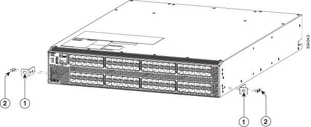
Use the following screw torques when installing the switch:
-
Captive screws: 4 in-lb (0.45 N·m)
-
M3 screws: 4 in-lb (0.45 N·m)
-
M4 screws: 12 in-lb (1.36 N·m)
-
M6 screws: 40 in-lb (4.5 N·m)
-
10-32 screws: 20 in-lb (2.26 N·m)
-
12-24 screws: 30 in-lb (3.39 N·m)
-
Required Equipment
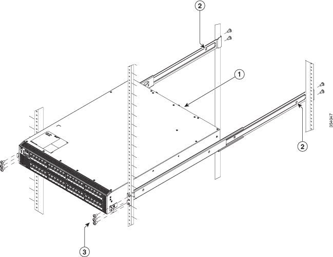
-
Eight customer-supplied 12-24 or 10-32 screws (required for attaching slider rails and mounting bracket to the mounting rails)
-
Number 1 and number 2 Phillips screwdrivers with torque capability
-
3/16-inch flat-blade screwdriver
-
Tape measure and level
-
ESD wrist strap or other grounding device
-
Anti static surface
The following additional items (not found in the accessory kit) are required to ground the chassis:
-
Grounding cable (6 AWG recommended), sized according to local and national installation requirements; the required length depends on the proximity of the switch to proper grounding facilities
Crimping tool large enough to accommodate girth of lug
-
Wire stripping tool
Unpacking and Inspecting the Switch
Caution |
When handling switch components, wear an ESD strap and handle modules by the carrier edges only. An ESD socket is provided on the chassis. For the ESD socket to be effective, the chassis must be grounded through the power cable, the chassis ground, or the metal-to-metal contact with a grounded rack. |
 Tip |
Keep the shipping container in case the chassis requires shipping in the future. |
Note |
If you purchased Cisco support through a Cisco reseller, contact the reseller directly. If you purchased support directly from Cisco, contact Cisco Technical Support at this URL: http://www.cisco.com/c/en/us/support/web/tsd-cisco-worldwide-contacts.html |
Note |
The switch is thoroughly inspected before shipment. If any damage occurred during transportation or any items are missing, contact your customer representative immediately. |
To inspect the shipment, follow these steps:
-
Compare the shipment to the equipment list provided by your customer service representative and verify that you have received all items, including the following:
-
Grounding lug kit
-
Rack-mount kit
-
ESD wrist strap
-
Cables and connectors
-
Any optional items ordered
-
-
Check for damage and report any discrepancies or damage to your customer service representative. Have the following information ready:
-
Invoice number of shipper (see packing slip)
-
Model and serial number of the damaged unit
-
Description of damage
-
Effect of damage on the installation
-
-
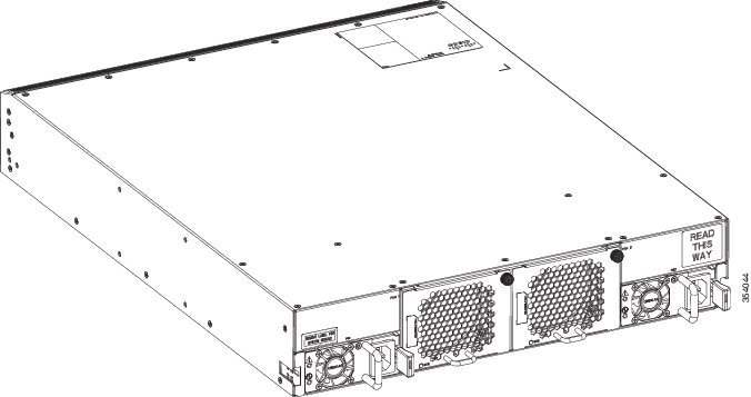
Check to be sure that all of the power supplies and the fan trays have the expected direction of airflow. Port-side-intake airflow modules have a burgundy coloring, and port-side exhaust airflow modules have blue coloring. The airflow direction must be the same for all modules.

 Feedback