Industrial Security Implementation Guide
Bias-Free Language
The documentation set for this product strives to use bias-free language. For the purposes of this documentation set, bias-free is defined as language that does not imply discrimination based on age, disability, gender, racial identity, ethnic identity, sexual orientation, socioeconomic status, and intersectionality. Exceptions may be present in the documentation due to language that is hardcoded in the user interfaces of the product software, language used based on RFP documentation, or language that is used by a referenced third-party product. Learn more about how Cisco is using Inclusive Language.
- Updated:
- July 20, 2021
Chapter: Industrial Security Implementation Guide
Industrial Security Implementation Guide
Cisco Cyber Vision
Installation
Global Center and Center
The Cyber Vision Center can be deployed as a virtual machine (VM) or as a hardware appliance. In this design, the Global Center and Centers were deployed as VMs on a Cisco Unified Computing System (UCS). For more information on installation and resource recommendations, see https://www.cisco.com/c/en/us/support/security/cyber-vision/series.html. As recommended in the Industrial Security Design Guide ( https://www.cisco.com/c/en/us/td/docs/solutions/Verticals/Industrial_Automation/IA_Horizontal/IA_Security/IA_Security_DG.html), the local Centers were validated with dual interfaces for management and sensor communication, respectively.
Sensors
There are two types of Cyber Vision Sensor: hardware and network. The hardware Sensor is the Cyber Vision IOx application installed on an Industrial Compute Gateway 3000 (IC3000) appliance. The network Sensor is the Cyber Vision IOx application installed on the supported switches. For information on installing a Sensor on the IC3000, see https://www.cisco.com/c/en/us/support/security/cyber-vision/series.html.
For network Sensors, there are three methods of installation: switch CLI, switch web interface, and Cyber Vision Center Extension. This guide will cover the network sensor installation using the Cyber Vision Center Extension feature. Refer to the Cyber Vision documentation for guidance on manual installations, if needed: https://www.cisco.com/c/en/us/support/security/cyber-vision/series.html.
Prior to any installation, the following configurations must be done on the switch:
■![]() Data export using Encapsulated Remote Switched Port Analyzer (ERSPAN)
Data export using Encapsulated Remote Switched Port Analyzer (ERSPAN)
Refer to Appendix for details on these configurations.
Once the switch has all necessary configurations, the sensor can be deployed using the Cyber Vision Center extension. First, install the extension by doing the following:
1.![]() Download the extension (.ext file) from cisco.com.
Download the extension (.ext file) from cisco.com.
2.![]() In Cyber Vision Center, navigate to Admin > Extensions.
In Cyber Vision Center, navigate to Admin > Extensions.
3.![]() Click the Import Extension File button and browse to the extension file.
Click the Import Extension File button and browse to the extension file.
After the extension has been installed, install a sensor by doing the following:
1.![]() In Cyber Vision Center, navigate to Admin > Sensors > Sensors.
In Cyber Vision Center, navigate to Admin > Sensors > Sensors.
2.![]() Click the Deploy Cisco Device button:
Click the Deploy Cisco Device button:
a.![]() In the IP address field, enter the IP address of the switch.
In the IP address field, enter the IP address of the switch.
b.![]() In the Port field, enter 443 for a network sensor.
In the Port field, enter 443 for a network sensor.
c.![]() In the User field, enter the user name to use to log in to the switch.
In the User field, enter the user name to use to log in to the switch.
d.![]() In the Password field, enter the password associated with the user account on the switch.
In the Password field, enter the password associated with the user account on the switch.
e.![]() In the Center IP field, you may enter the IP address of the Center that the sensors will use for communication. For dual interface Center deployments, it is recommended to enter the eth1 IP address here.
In the Center IP field, you may enter the IP address of the Center that the sensors will use for communication. For dual interface Center deployments, it is recommended to enter the eth1 IP address here.
f.![]() Under Capture mode, you may choose from the various options to change what data the sensor will process. In this validation, the Optimal (default) option was selected.
Under Capture mode, you may choose from the various options to change what data the sensor will process. In this validation, the Optimal (default) option was selected.
h.![]() More configuration fields will show. In the Capture IP address field, enter the ERSPAN destination IP address for the sensor.
More configuration fields will show. In the Capture IP address field, enter the ERSPAN destination IP address for the sensor.
i.![]() In the Capture prefix length field, enter the prefix associated with the ERSPAN IP address.
In the Capture prefix length field, enter the prefix associated with the ERSPAN IP address.
j.![]() In the Capture VLAN number field, enter the monitoring session destination VLAN
In the Capture VLAN number field, enter the monitoring session destination VLAN
k.![]() In the Collection IP address field, enter the IP address of the eth0 interface of the sensor. This is the IP address that will be used for communication with the Center.
In the Collection IP address field, enter the IP address of the eth0 interface of the sensor. This is the IP address that will be used for communication with the Center.
l.![]() In the Collection prefix length field, enter the prefix associated with the sensor IP address.
In the Collection prefix length field, enter the prefix associated with the sensor IP address.
m.![]() In the Collection gateway field, enter the IP address of the gateway that the sensor will use for communicating through the network.
In the Collection gateway field, enter the IP address of the gateway that the sensor will use for communicating through the network.
n.![]() In the Collection VLAN number, enter the VLAN of the sensor IP address.
In the Collection VLAN number, enter the VLAN of the sensor IP address.
o.![]() Under Application type, click the radio button of the type of sensor you wish to deploy. For the Passive and Active Discovery option, additional information is required:
Under Application type, click the radio button of the type of sensor you wish to deploy. For the Passive and Active Discovery option, additional information is required:
i. In the IP address field, enter an IP address for the sensor to use in Active Discovery. Note that this IP address needs to be from the same subnet as the end devices you wish to discover. If active discovery is necessary on the same subnet as the sensor itself, you can click the USE COLLECTION button.
ii. In the Prefix length field, enter the prefix associated with the IP address.
iii. In the VLAN field, enter the VLAN for the subnet.
iv. (Optional) Click the ADD ONE button to configure another Active Discovery interface. This secondary interface should be configured for doing active discovery on a different subnet than what was specified for the first interface.
Configuration
Licensing
Cyber Vision Center makes use of Cisco Smart Software Licensing, which can be installed via online or offline methods. For online licensing, the Center must be able to communicate externally to Cisco.com. To license Cyber Vison Center using the online method, do the following:
1.![]() Ensure the Cisco Cyber Vision Advantage license is present in your Smart Software Account.
Ensure the Cisco Cyber Vision Advantage license is present in your Smart Software Account.
2.![]() Copy the token associated with the Cyber Vision Advantage license from the Smart Software Licensing site.
Copy the token associated with the Cyber Vision Advantage license from the Smart Software Licensing site.
3.![]() In Cyber Vision Center, navigate to Admin > License.
In Cyber Vision Center, navigate to Admin > License.
5.![]() In the Product Instance Registration Token field, paste the token.
In the Product Instance Registration Token field, paste the token.
Presets
Presets allow the user to customize how components are displayed and grouped. In addition, the presets allow the user to quickly navigate to device activity, vulnerability, and event information. The Cisco Cyber Vision Center comes with default presets, such as Control Systems Management, but the user can create their own by doing the following:
1.![]() In Cyber Vision Center, navigate to Explore.
In Cyber Vision Center, navigate to Explore.
2.![]() At the top, click the New Preset button. Provide a name and an optional description.
At the top, click the New Preset button. Provide a name and an optional description.
3.![]() The new preset will now show in the My preset list. Click the preset rectangle to display the preset dashboard and filter options.
The new preset will now show in the My preset list. Click the preset rectangle to display the preset dashboard and filter options.
4.![]() From the left Criteria menu, select the necessary options to filter data included in the Preset. Click the Save icon at the top when finished.
From the left Criteria menu, select the necessary options to filter data included in the Preset. Click the Save icon at the top when finished.
Active Discovery
The Active Discovery feature allows the sensor to send a broadcast message to a given subnet to retrieve device information. To initiate Active Discovery, do the following:
1.![]() Create a Preset that is filtered for the Sensor with Active Discovery enabled.
Create a Preset that is filtered for the Sensor with Active Discovery enabled.
3.![]() Click the Edit Active Discovery Settings icon.
Click the Edit Active Discovery Settings icon.
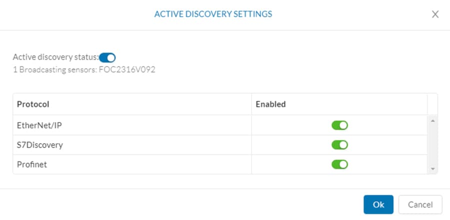
4.![]() Click the Active Discovery Status button to enable Active Discovery.
Click the Active Discovery Status button to enable Active Discovery.
5.![]() Click the button to the right of each protocol to enable.
Click the button to the right of each protocol to enable.
Figure 1 Enable Active Discovery
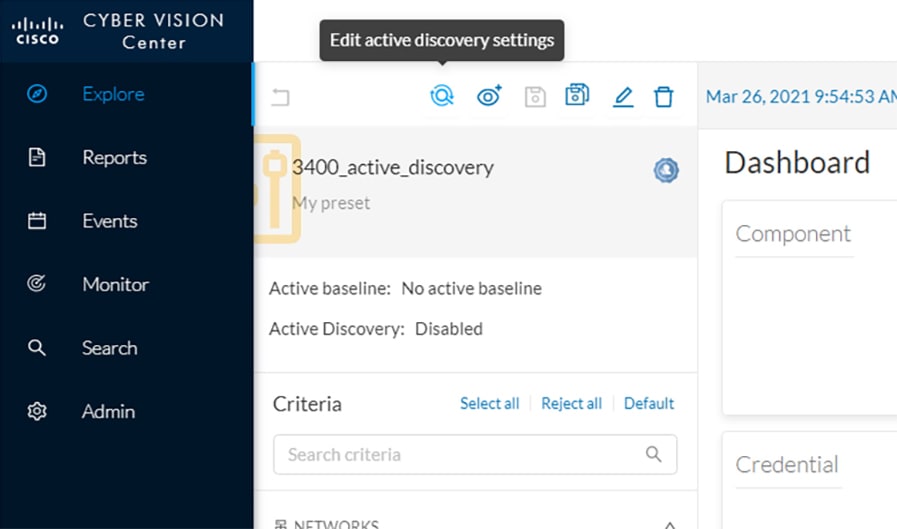
Figure 2 Active Discovery Settings
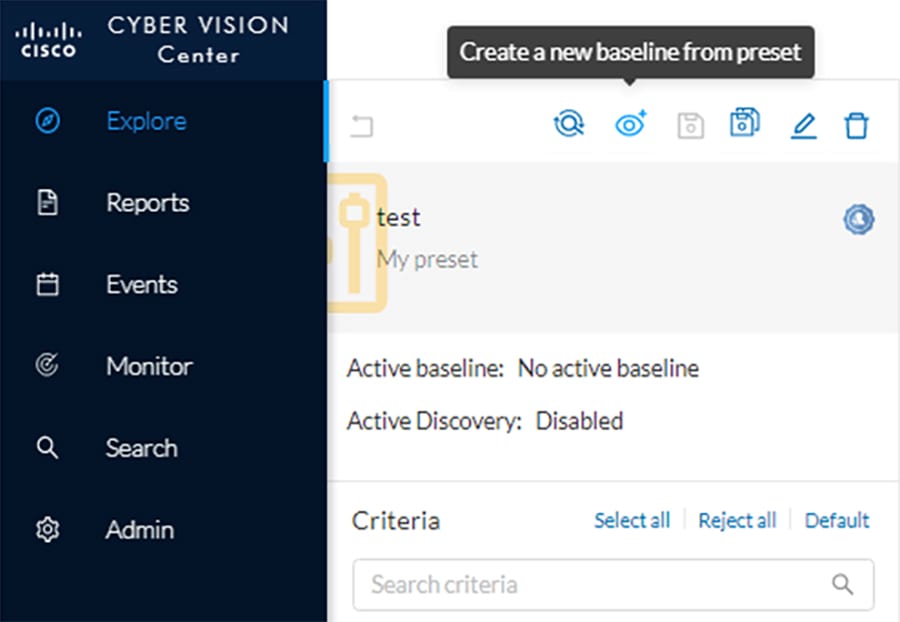
Baseline
The Baseline feature helps to monitor given devices and/or communication for anomalous activity. To create a Baseline, do the following:
1.![]() Create a Preset for the given devices and/or activity to be monitored.
Create a Preset for the given devices and/or activity to be monitored.
3.![]() Click the Create a New Baseline from Preset icon.
Click the Create a New Baseline from Preset icon.
a.![]() In the Name field, enter a name for the Baseline.
In the Name field, enter a name for the Baseline.
b.![]() Optionally, provide a Description.
Optionally, provide a Description.
Upgrade
Upgrades can be done from the Center to upgrade both the Center and the Sensors. To upgrade the Center and Sensors, do the following:
1.![]() Download the combined upgrade file (.dat) from Cisco.com
Download the combined upgrade file (.dat) from Cisco.com
2.![]() In Cyber Vision Center, navigate to Admin > System.
In Cyber Vision Center, navigate to Admin > System.
3.![]() Click the System Update button and browse to the upgrade file.
Click the System Update button and browse to the upgrade file.
4.![]() The Center will verify if you want to run the update. Click the Yes, update button.
The Center will verify if you want to run the update. Click the Yes, update button.
For information on individual device upgrades, refer to the Cyber Vision documentation: https://www.cisco.com/c/en/us/support/security/cyber-vision/series.html.
Global Center and Local Center
The Global Center aggregates flows, devices, and events from local Centers. To connect a local Center to the Global Center, do the following:
1.![]() In the local Center, navigate to Admin > System.
In the local Center, navigate to Admin > System.
2.![]() Scroll to the bottom and copy the string below Certificate fingerprint.
Scroll to the bottom and copy the string below Certificate fingerprint.
3.![]() In Global Center, navigate to Admin > System > Management.
In Global Center, navigate to Admin > System > Management.
4.![]() Click the Register a Center button.
Click the Register a Center button.
a.![]() In the Name field, enter a name for the local center.
In the Name field, enter a name for the local center.
b.![]() In the Fingerprint field, paste the certificate fingerprint string from the local Center.
In the Fingerprint field, paste the certificate fingerprint string from the local Center.
5.![]() In Global Center, navigate to Admin > System.
In Global Center, navigate to Admin > System.
6.![]() Scroll to the bottom and copy the string below Certificate fingerprint.
Scroll to the bottom and copy the string below Certificate fingerprint.
7.![]() In the local Center, navigate to Admin > System.
In the local Center, navigate to Admin > System.
8.![]() Scroll down and click the Enroll button under Enroll to a Global Center.
Scroll down and click the Enroll button under Enroll to a Global Center.
a.![]() In the Global Center fingerprint field, paste the fingerprint copied from the Global Center.
In the Global Center fingerprint field, paste the fingerprint copied from the Global Center.
b.![]() In the Global Center IP address field, enter the IP address of the Global Center.
In the Global Center IP address field, enter the IP address of the Global Center.
Knowledge Database
The Knowledge Database (DB) includes vulnerability data for various hardware, firmware, and the like. The Knowledge DB is installed on the Global Center and pushed to the local Centers and must be updated separately from the Cyber Vision software itself. To install a Knowledge DB update, do the following:
1.![]() Download the latest Cyber Vision Knowledge DB (.db) file from Cisco.com.
Download the latest Cyber Vision Knowledge DB (.db) file from Cisco.com.
2.![]() In Global Center, navigate to Admin > System.
In Global Center, navigate to Admin > System.
3.![]() Under Knowledge DB, click the Import a Knowledge DB button and browse to the update file.
Under Knowledge DB, click the Import a Knowledge DB button and browse to the update file.
Integrations
Cisco SecureX
The Cyber Vision Center and Cisco SecureX integration allows the user to further investigate IP addresses detected by Cyber Vision in SecureX, which may provide more insight about the entity from the wealth of information collected in SecureX. To connect Cyber Vision Center to SecureX, do the following:
1.![]() In Cyber Vision Center, navigate to Admin > Integrations > CTR.
In Cyber Vision Center, navigate to Admin > Integrations > CTR.
2.![]() Click the Configure button.
Click the Configure button.
a.![]() From the Platform drop-down list, choose the Threat Response that is geographically (and presumably logically) closest to the Cyber Vision Center.
From the Platform drop-down list, choose the Threat Response that is geographically (and presumably logically) closest to the Cyber Vision Center.
Analysis
Presets
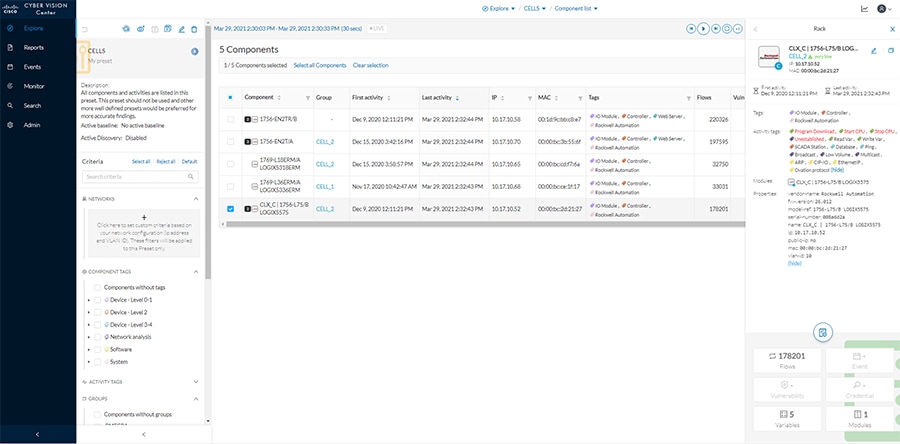
Presets provide different views to look at the data captured by the Cyber Vision Sensor, and can be tailored to highlight specific components or activity to speed analysis. Some tips for using Presets:
■![]() Components—These are the unique devices seen on the network, and each contains specific details about vendor, device type, protocol, and so on. From the Components button on the Preset Dashboard, you can see a list of each component and by clicking one, more details about the component will show in a Component pane on the right. From that pane, click the Technical Sheet icon to view full details about the component.
Components—These are the unique devices seen on the network, and each contains specific details about vendor, device type, protocol, and so on. From the Components button on the Preset Dashboard, you can see a list of each component and by clicking one, more details about the component will show in a Component pane on the right. From that pane, click the Technical Sheet icon to view full details about the component.
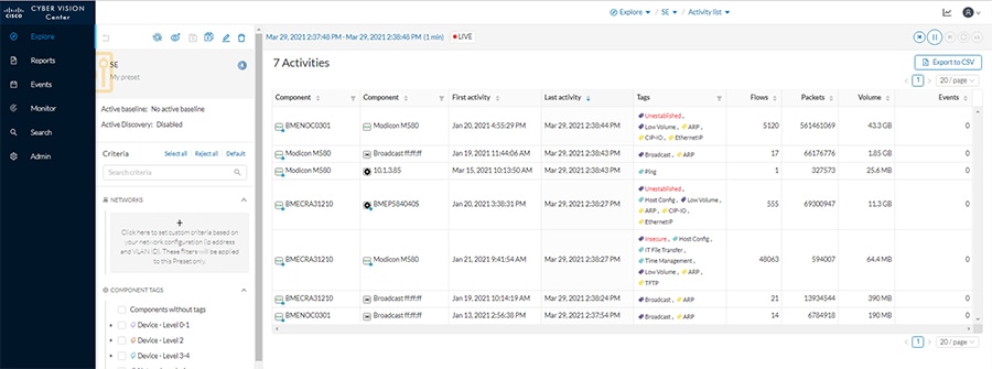
■![]() Activities—These are the communication flows between components. From the Activities button on the Preset Dashboard, you can view these communications based on the time reference selected.
Activities—These are the communication flows between components. From the Activities button on the Preset Dashboard, you can view these communications based on the time reference selected.
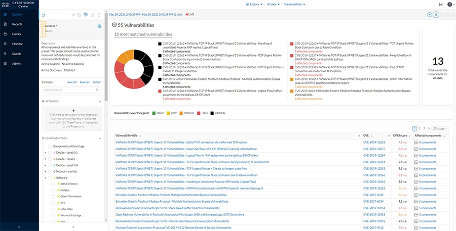
■![]() Vulnerabilities—The Knowledge DB identifies known vulnerabilities for devices based on their hardware, firmware, protocol, and so on. From the Vulnerabilities button on the Preset Dashboard, you can view all identified vulnerabilities for the components included in that preset. In the table, click the link in the Vulnerability title column for a given vulnerability to view more details, including the associated Common Vulnerabilities and Exposures (CVE) identifier and potential fixes. Each vulnerability can be acknowledged by the analyst to remove it from the list.
Vulnerabilities—The Knowledge DB identifies known vulnerabilities for devices based on their hardware, firmware, protocol, and so on. From the Vulnerabilities button on the Preset Dashboard, you can view all identified vulnerabilities for the components included in that preset. In the table, click the link in the Vulnerability title column for a given vulnerability to view more details, including the associated Common Vulnerabilities and Exposures (CVE) identifier and potential fixes. Each vulnerability can be acknowledged by the analyst to remove it from the list.
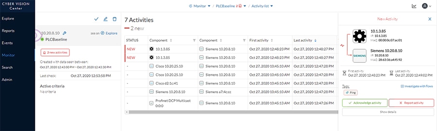
■![]() Baseline—If a baseline has been created for a Preset, it can highlight changes in activity or components beyond what is expected from the baseline. Click the link next to Active Baseline from the Preset side menu to view baseline updates. The baseline will show a map of the devices and their communications, highlighting new flows with a solid red line and any changed flows with a dashed line. From this view you can also click the New Activity or the Changed Activities button on the left to see details and acknowledge or report the activities. You can also see all baselines from the Monitor option on the main left menu.
Baseline—If a baseline has been created for a Preset, it can highlight changes in activity or components beyond what is expected from the baseline. Click the link next to Active Baseline from the Preset side menu to view baseline updates. The baseline will show a map of the devices and their communications, highlighting new flows with a solid red line and any changed flows with a dashed line. From this view you can also click the New Activity or the Changed Activities button on the left to see details and acknowledge or report the activities. You can also see all baselines from the Monitor option on the main left menu.
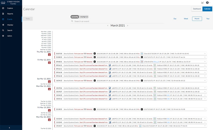
Reports and Events
Cyber Vision Center provides various reports for the user to download in a Microsoft Excel or HTML format for offline analysis. Such reports can be useful for further investigation and remediation. Events in Cyber Vision Center highlight new activity, changes in the environment, and so on, and classify each by severity. Note that if activity from a baseline is reported, it will also show in the Events list.
Figure 8 Cisco Cyber Vision Events
Packet Capture
Cyber Vision Center provides the capability to run a packet capture directly on a Cyber Vision Sensor for further analysis and troubleshooting. The data collected will be the raw traffic seen by the Sensor and is useful for understanding traffic flows and specific industrial traits and activities on devices. To run a packet capture on a sensor, do the following:
1.![]() In Cyber Vision Center, navigate to Admin > Sensors > Capture.
In Cyber Vision Center, navigate to Admin > Sensors > Capture.
2.![]() In the Capture Actions column, click the Start Recording link for a given sensor.
In the Capture Actions column, click the Start Recording link for a given sensor.
3.![]() When finished, click the Stop Recording link for the sensor.
When finished, click the Stop Recording link for the sensor.
4.![]() Click the Download link to download the packet capture file.
Click the Download link to download the packet capture file.
ISA 3000
Installation
Hardware Installation
For physical installation guidance, refer to https://www.cisco.com/c/en/us/support/security/industrial-security-appliance-isa/series.html#~tab-documents.
Software Installation
Firepower Threat Defense (FTD) provides robust security, combining traditional access control with proprietary intrusion detection. To install FTD on the ISA 3000, refer to: https://www.cisco.com/c/en/us/support/security/industrial-security-appliance-isa/series.html#~tab-documents.
Connecting to the Network
The ISA 3000 has a dedicated management interface used for communications with the Firepower Management Center (FMC). This port should be connected to a switch that will be able to transmit the traffic through the network to the FMC. In addition, there are four data ports that can be used for all of the firewall transactions on network traffic; these interfaces are connected to the respective switches for which traffic inspection is required. For this design, two ISA 3000 ports were configured as a transparent inline set with the adjacent switch ports configured as trunk ports. This configuration allows multiple VLANs to traverse the firewall as a “bump in the wire”. One interface is connected to the upstream or “outside” switch, and the other is connected to the downstream or “inside” switch. Note that inline sets require specific port pairings: port 1 and 2 or port 3 and 4.
On the adjacent switches to the ISA 3000, the ports should be configured like the following example:
Configuration
Connection to FMC
After FTD has been installed, run the following command to connect to the FMC:
The registration key is a unique string that will be used on the FMC to add the FTD device. If the FTD device is behind a NAT boundary, do the following when configuring the manager:
In addition, NTP needs to be synced to the same time as FMC. To update the time on the FTD device, do the following from the CLI:
To make the ISA 3000 run in transparent mode, do the following:
Device Configuration in FMC
To add the FTD device to the FMC, do the following:
1.![]() In the FMC web UI, navigate to Devices > Device Management.
In the FMC web UI, navigate to Devices > Device Management.
2.![]() Click the Add button and choose Device.
Click the Add button and choose Device.
a.![]() In the Host field, enter the IP address of the FTD device.
In the Host field, enter the IP address of the FTD device.
b.![]() In the Display Name field, enter a name for the FTD device.
In the Display Name field, enter a name for the FTD device.
c.![]() In the Registration Key field, enter the unique registration key used on the FTD device to connect to the FMC.
In the Registration Key field, enter the unique registration key used on the FTD device to connect to the FMC.
d.![]() Optionally, in the Group drop-down list choose a group for the FTD device.
Optionally, in the Group drop-down list choose a group for the FTD device.
e.![]() In the Access Control Policy drop-down list, choose the appropriate policy to apply to the device.
In the Access Control Policy drop-down list, choose the appropriate policy to apply to the device.
f.![]() Under Smart Licensing, check the appropriate license checkboxes for your needs.
Under Smart Licensing, check the appropriate license checkboxes for your needs.
g.![]() Optionally, in the Unique NAT ID field enter the NAT ID used on the FTD device.
Optionally, in the Unique NAT ID field enter the NAT ID used on the FTD device.
The FTD device will now show on the Device Management page. Click the pencil icon on the right to further configure the device:
1.![]() Choose Interfaces from the top menu
Choose Interfaces from the top menu
2.![]() Click the pencil icon to the right of each interface and do the following:
Click the pencil icon to the right of each interface and do the following:
a.![]() In the Name field, enter a name for the interface.
In the Name field, enter a name for the interface.
b.![]() Check the Enabled check box.
Check the Enabled check box.
c.![]() Check the Propagate Security Group Tag check box.
Check the Propagate Security Group Tag check box.
3.![]() Repeat Step 2 for each interface being used.
Repeat Step 2 for each interface being used.
4.![]() Choose Inline Sets from the top menu.
Choose Inline Sets from the top menu.
5.![]() Click the Add Inline Set button.
Click the Add Inline Set button.
a.![]() In the Name field, enter a name for the Inline Set.
In the Name field, enter a name for the Inline Set.
b.![]() The Available Interfaces Pairs list will show the pair options to use in the Inline Set. Choose the necessary pair(s) and click the Add button to move it to the Selected Interface Pair list.
The Available Interfaces Pairs list will show the pair options to use in the Inline Set. Choose the necessary pair(s) and click the Add button to move it to the Selected Interface Pair list.
c.![]() Choose the Advanced option on the top menu of the Add Inline Set dialog box.
Choose the Advanced option on the top menu of the Add Inline Set dialog box.
d.![]() Check the Propagate Link State check box.
Check the Propagate Link State check box.
6.![]() Choose Interfaces from the top menu.
Choose Interfaces from the top menu.
7.![]() Click the pencil icon to the right of an interface used in an Inline Set.
Click the pencil icon to the right of an interface used in an Inline Set.
a.![]() From the Security Zone drop-down list, choose either inline_inside or inline_outside (depending on the interface being modified).
From the Security Zone drop-down list, choose either inline_inside or inline_outside (depending on the interface being modified).
8.![]() Repeat Step 7 for other interfaces being used in an Inline Set.
Repeat Step 7 for other interfaces being used in an Inline Set.
9.![]() Click the Save button at the top right.
Click the Save button at the top right.
The configuration must be deployed to the FTD device by doing the following:
1.![]() In FMC, navigate to Deploy > Deployment.
In FMC, navigate to Deploy > Deployment.
High Availability
For a High Availability (HA) FTD deployment, do the following:
1.![]() Register, configure, and deploy each FTD device in FMC as described above.
Register, configure, and deploy each FTD device in FMC as described above.
2.![]() Connect the two devices using the same interface on each FTD device.
Connect the two devices using the same interface on each FTD device.
3.![]() In FMC, navigate to Devices > Device Management.
In FMC, navigate to Devices > Device Management.
4.![]() Click the Add button and choose High Availability.
Click the Add button and choose High Availability.
a.![]() In the Name field, enter a name for the HA pair.
In the Name field, enter a name for the HA pair.
b.![]() From the Device Type drop-down list, choose Firepower Threat Defense.
From the Device Type drop-down list, choose Firepower Threat Defense.
c.![]() From the Primary Peer drop-down list, choose the FTD device that will be the primary member of the HA pair (typically the active node).
From the Primary Peer drop-down list, choose the FTD device that will be the primary member of the HA pair (typically the active node).
d.![]() From the Secondary Peer drop-down list, choose the FTD device that will be the secondary member of the HA pair (typically the standby node).
From the Secondary Peer drop-down list, choose the FTD device that will be the secondary member of the HA pair (typically the standby node).
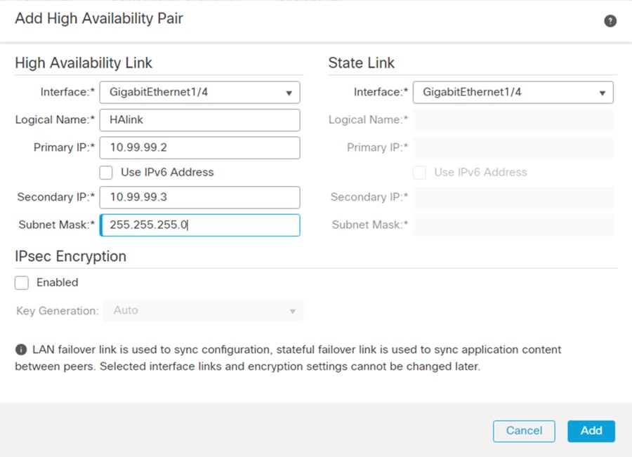
f.![]() Under High Availability Link :
Under High Availability Link :
i. From the Interface drop-down list, choose the interface being used to connect the two FTD devices.
ii. In the Logical Name field, enter a name.
iii. In the Primary IP field, enter an IP address. This IP address must be in a unique subnet not being used elsewhere in the architecture.
iv. In the Secondary IP field, enter an IP address in the same subnet as the Primary IP address.
v. In the Subnet Mask field, enter a subnet mask for the two IP addresses.
g.![]() Under State Link:, from the Interface drop-down list, choose Same as LAN Failover Link.
Under State Link:, from the Interface drop-down list, choose Same as LAN Failover Link.
Figure 9 High Availability Pair Configuration
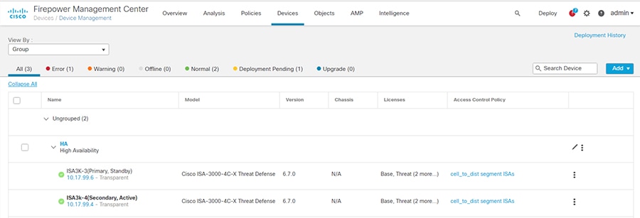
The HA pair will be grouped together on the Device Management page, and configuration can be viewed or edited only for the active member. To change the roles of the FTD devices, click the vertical ellipses icon to the right of the HA pair and choose Switch Active Peer.
Figure 10 FMC Device List with High Availability Pair
Software Upgrade
The FTD software can be upgraded through the FMC. For details on pushing an upgrade, see https://www.cisco.com/c/en/us/td/docs/security/firepower/upgrade/fpmc-upgrade-guide.html.
Firepower Management Center
Installation
This design was validated with a virtual FMC. For details on installing the virtual FMC, see https://www.cisco.com/c/en/us/support/security/defense-center-virtual-appliance/series.html.
Configuration
Basic Configuration
After deploying the virtual FMC, the IP address, administrator password, and the End User License Agreement (EULA), and so on need to be configured through the CLI to enable web interface connectivity. The initial log in to the FMC web interface will guide you through updating DNS as well as NTP. For details, refer to https://www.cisco.com/c/en/us/support/security/defense-center-virtual-appliance/products-installation-guides-list.html.
Additional configurations can be adjusted in FMC by doing the following:
1.![]() In FMC, navigate to System > Configuration.
In FMC, navigate to System > Configuration.
2.![]() Navigate to necessary options on the left menu bar to view specific settings.
Navigate to necessary options on the left menu bar to view specific settings.
Licensing
The FMC is licensed through Cisco Smart Software Licensing and requires connectivity to communicate externally to Cisco.com. In addition, the FMC maintains licenses for the subsequent FTD devices it manages. To view or update licenses, do the following:
1.![]() In FMC, navigate to System > Licenses > Smart Licenses.
In FMC, navigate to System > Licenses > Smart Licenses.
2.![]() The FMC will automatically synchronize to Cisco.com. Ensure your licenses are present in your Cisco Smart Software account. Click the Synchronize icon to refresh the license status.
The FMC will automatically synchronize to Cisco.com. Ensure your licenses are present in your Cisco Smart Software account. Click the Synchronize icon to refresh the license status.
Network Objects
Network objects are IP addresses or groups of IP addresses to be used in other configurations such as access control rules. To add or update Network Objects, do the following:
1.![]() In FMC, navigate to Objects > Object Management.
In FMC, navigate to Objects > Object Management.
2.![]() The Network page will be displayed. From the Add Network drop-down list, choose the Add Object option.
The Network page will be displayed. From the Add Network drop-down list, choose the Add Object option.
a.![]() In the Name field, enter a name for the entity.
In the Name field, enter a name for the entity.
b.![]() Optionally, provide a note in the Description field describing the object.
Optionally, provide a note in the Description field describing the object.
c.![]() Under Network, click the radio button for your preferred input method. For example, click the Host radio button and enter the IP address of the entity in the field box.
Under Network, click the radio button for your preferred input method. For example, click the Host radio button and enter the IP address of the entity in the field box.
If two or more IP addresses need to be grouped for use elsewhere in FMC, do the following:
1.![]() From the Objects > Object Management > Network page, choose the Add Group option from the Add Network drop-down list.
From the Objects > Object Management > Network page, choose the Add Group option from the Add Network drop-down list.
a.![]() In the Name field, enter a name for the group.
In the Name field, enter a name for the group.
b.![]() Optionally, provide a note in the Description field describing the group.
Optionally, provide a note in the Description field describing the group.
c.![]() From the Available Networks list, choose one or more options and click the Add button to move them to the Selected Networks list.
From the Available Networks list, choose one or more options and click the Add button to move them to the Selected Networks list.
Access Control Policy
An Access Control Policy consists of access control rules and other settings to determine the inspection behavior of the FTD device. For each FTD device, only one Access Control Policy can be applied at any given time. To create an Access Control Policy, do the following:
1.![]() In FMC, navigate to Policies > Access Control > Access Control.
In FMC, navigate to Policies > Access Control > Access Control.
2.![]() The Rules page will be displayed. Click the New Policy button.
The Rules page will be displayed. Click the New Policy button.
a.![]() In the Name field, enter a name for the policy.
In the Name field, enter a name for the policy.
b.![]() In the Description field, enter a description for the policy.
In the Description field, enter a description for the policy.
c.![]() From the Select Base Policy drop-down list, choose None.
From the Select Base Policy drop-down list, choose None.
d.![]() Under Default Action, click the radio button of the desired option. This will be the action taken if traffic does not match any of the user-created rules.
Under Default Action, click the radio button of the desired option. This will be the action taken if traffic does not match any of the user-created rules.
–![]() Block all traffic —This option will drop traffic.
Block all traffic —This option will drop traffic.
–![]() Intrusion Prevention —This option will pass traffic to be analyzed against the default Balanced Security and Connectivity Intrusion Policy.
Intrusion Prevention —This option will pass traffic to be analyzed against the default Balanced Security and Connectivity Intrusion Policy.
–![]() Network Discovery —This option will allow traffic to pass and populate the Host database for the IP addresses seen communicating.
Network Discovery —This option will allow traffic to pass and populate the Host database for the IP addresses seen communicating.
e.![]() Under Available Devices, choose the FTD device for which this policy will apply. Click the Add to Policy button.
Under Available Devices, choose the FTD device for which this policy will apply. Click the Add to Policy button.
To add Access Control Rules to the newly created Policy, do the following:
1.![]() From the Access Control Policy page, click the pencil icon to the right of the Access Control Policy.
From the Access Control Policy page, click the pencil icon to the right of the Access Control Policy.
a.![]() In the Name field, enter a name for the rule.
In the Name field, enter a name for the rule.
b.![]() Check the Enabled check box.
Check the Enabled check box.
c.![]() From the Action drop-down list, choose the desired segmentation action:
From the Action drop-down list, choose the desired segmentation action:
–![]() Allow —This option will pass the matched traffic for any further inspection (if any).
Allow —This option will pass the matched traffic for any further inspection (if any).
–![]() Trust —This option will pass the matched traffic without further inspection.
Trust —This option will pass the matched traffic without further inspection.
–![]() Monitor —This option will pass the traffic and automatically enable logging of the matched traffic.
Monitor —This option will pass the traffic and automatically enable logging of the matched traffic.
–![]() Block —This option will drop the traffic.
Block —This option will drop the traffic.
–![]() Block with reset —This option will drop the traffic and reset the connection.
Block with reset —This option will drop the traffic and reset the connection.
–![]() Interactive Block —This option will allow the user to proceed or stop the connection.
Interactive Block —This option will allow the user to proceed or stop the connection.
–![]() Interactive Block with reset —This option will block all non-web traffic and allow the user to proceed or stop the web connection.
Interactive Block with reset —This option will block all non-web traffic and allow the user to proceed or stop the web connection.
d.![]() Optionally, enter a placement for the rule with the Insert drop-down list.
Optionally, enter a placement for the rule with the Insert drop-down list.
e.![]() Optionally, choose a time from the Time Range drop-down list or click the plus (+) icon to create a new time range.
Optionally, choose a time from the Time Range drop-down list or click the plus (+) icon to create a new time range.
f.![]() Choose the tabs needed to specify the rule criteria. Note that these are optional and are used to narrow the matching criteria and provide additional inspection. If nothing is selected, all traffic will match the rule and be subject to the Action specified:
Choose the tabs needed to specify the rule criteria. Note that these are optional and are used to narrow the matching criteria and provide additional inspection. If nothing is selected, all traffic will match the rule and be subject to the Action specified:
–![]() Zones —These are the “inside” or “outside” zones specified on the FTD device interfaces.
Zones —These are the “inside” or “outside” zones specified on the FTD device interfaces.
–![]() Networks —These are traditional IP addresses and subnets. Note that Network Objects or Groups can be used here.
Networks —These are traditional IP addresses and subnets. Note that Network Objects or Groups can be used here.
–![]() VLAN Tags —These are VLAN tag objects created by the user. Note these can only be used for inline sets.
VLAN Tags —These are VLAN tag objects created by the user. Note these can only be used for inline sets.
–![]() Users —If AD and FMC have been integrated, specific users can be added to the rule.
Users —If AD and FMC have been integrated, specific users can be added to the rule.
–![]() Applications —Applications, such as Microsoft PowerPoint, Common Industrial Protocol (CIP), Firefox, and so on can be specified.
Applications —Applications, such as Microsoft PowerPoint, Common Industrial Protocol (CIP), Firefox, and so on can be specified.
–![]() Ports —These are the Layer 4 ports used in the transaction.
Ports —These are the Layer 4 ports used in the transaction.
–![]() URLs —These are website addresses in the system or created by the user.
URLs —These are website addresses in the system or created by the user.
–![]() SGT/ISE Attributes —If Cisco Identity Services Engine (ISE) and FMC have been integrated, specific security group tags (SGTs) can be added to the rule.
SGT/ISE Attributes —If Cisco Identity Services Engine (ISE) and FMC have been integrated, specific security group tags (SGTs) can be added to the rule.
1. Intrusion Policy—An intrusion policy can be applied here. If the traffic matches the access control rule, it will then analyze the traffic against the specified intrusion policy and take action based on the intrusion policy settings.
2. File Policy —A file policy can be applied here. If the traffic matches the access control rule and there is a file included in the transaction, it will be inspected against the file policy and take action based on the file policy settings.
–![]() Logging —This will ensure the connection event is logged for the matched traffic, which can provide useful information for analysis and troubleshooting. It is recommended to at least check the Log at Beginning of Connection check box if logging is desired.
Logging —This will ensure the connection event is logged for the matched traffic, which can provide useful information for analysis and troubleshooting. It is recommended to at least check the Log at Beginning of Connection check box if logging is desired.
–![]() Comments —Provide notes about the rule.
Comments —Provide notes about the rule.
3.![]() Repeat Step 2 for any additional rules, being mindful of rule order which can impact action taken as well as processing. Refer to the Industrial Security Design Guide for best practices.
Repeat Step 2 for any additional rules, being mindful of rule order which can impact action taken as well as processing. Refer to the Industrial Security Design Guide for best practices.
To apply the Access Control Policy, do the following:
1.![]() In FMC, navigate to Deploy > Deployment.
In FMC, navigate to Deploy > Deployment.
Intrusion Policy
Intrusion policies make use of Cisco Talos intelligence and research to find abnormal or malicious activity in network traffic. There are thousands of Snort signatures to use for detection, many of which are grouped into categories for ease of configuration, such as OS-Windows or Protocol-SCADA. If an access rule has an intrusion policy applied, the traffic will first be matched against the traditional access control and if allowed, it will then be matched against the intrusion rules contained within the intrusion policy. To create an intrusion policy, do the following:
1.![]() In FMC, navigate to Policies > Access Control > Intrusion.
In FMC, navigate to Policies > Access Control > Intrusion.
2.![]() Click the Create Policy button.
Click the Create Policy button.
a.![]() In the Name field, enter a name for the policy.
In the Name field, enter a name for the policy.
b.![]() Optionally, in the Description field, provide detail about the policy.
Optionally, in the Description field, provide detail about the policy.
c.![]() Optionally, check the Drop when Inline check box. This means when the FTD device is deployed with an Inline set, the traffic can be dropped if successfully matched against an intrusion rule (with additional configuration).
Optionally, check the Drop when Inline check box. This means when the FTD device is deployed with an Inline set, the traffic can be dropped if successfully matched against an intrusion rule (with additional configuration).
d.![]() In the Base Policy drop-down list, choose an option for the initial policy configuration:
In the Base Policy drop-down list, choose an option for the initial policy configuration:
–![]() Balanced Security and Connectivity —This option does not favor threat detection or speed, but rather has an average amount of intrusion rules applied so as to not overload processing.
Balanced Security and Connectivity —This option does not favor threat detection or speed, but rather has an average amount of intrusion rules applied so as to not overload processing.
–![]() Connectivity Over Security —Throughput and traffic connections are prioritized over inspection, therefore there are less intrusion rules applied.
Connectivity Over Security —Throughput and traffic connections are prioritized over inspection, therefore there are less intrusion rules applied.
–![]() Maximum Detection —This contains the most enabled intrusion rules of the default policies, making security the highest priority.
Maximum Detection —This contains the most enabled intrusion rules of the default policies, making security the highest priority.
–![]() No Rules Active —This does not enable any intrusion rules and allows for the user to create a truly custom rule set.
No Rules Active —This does not enable any intrusion rules and allows for the user to create a truly custom rule set.
–![]() Security Over Connectivity —Intrusion detection takes precedence over throughput and traffic connections.
Security Over Connectivity —Intrusion detection takes precedence over throughput and traffic connections.
e.![]() Click the Create Policy button.
Click the Create Policy button.
If any customizations to the policy are necessary, click the pencil icon to the right of the policy. To add additional rules to the policy, do the following:
1.![]() On the Policy Information page, click the Manage Rules button.
On the Policy Information page, click the Manage Rules button.
2.![]() Browse through the categories on the left menu to see available rules. In addition, rules can be searched for using the Filter field. For example, to find all CIP related rules, do the following:
Browse through the categories on the left menu to see available rules. In addition, rules can be searched for using the Filter field. For example, to find all CIP related rules, do the following:
a.![]() In the Rules menu, navigate to Category > protocol-scada. The Filter field will now show: Category:”protocol-scada”.
In the Rules menu, navigate to Category > protocol-scada. The Filter field will now show: Category:”protocol-scada”.
b.![]() Add the following to the Filter field: CIP. The Filter field will now show: Category:”protocol-scada:”CIP. Press Enter.
Add the following to the Filter field: CIP. The Filter field will now show: Category:”protocol-scada:”CIP. Press Enter.
3.![]() Click the GID check box next to any desired rules and from the Rule State drop-down list, choose the necessary action:
Click the GID check box next to any desired rules and from the Rule State drop-down list, choose the necessary action:
–![]() Generate Events —If the traffic matches the intrusion rule, an event will show in the Intrusion Events. The traffic will not be dropped.
Generate Events —If the traffic matches the intrusion rule, an event will show in the Intrusion Events. The traffic will not be dropped.
–![]() Drop and Generate Events —If the traffic matches the intrusion rule, an event will be created and the traffic will be dropped.
Drop and Generate Events —If the traffic matches the intrusion rule, an event will be created and the traffic will be dropped.
–![]() Disable —This is for any rule you do not wish the traffic to be inspected against.
Disable —This is for any rule you do not wish the traffic to be inspected against.
4.![]() After all rules have been added, click the Back link at the top of the Rules page.
After all rules have been added, click the Back link at the top of the Rules page.
5.![]() From the Policy Information menu, click Policy Layers. The details of the default rules and any customizations are shown. When finished reviewing, click the Back link at the top of the Policy Layers page.
From the Policy Information menu, click Policy Layers. The details of the default rules and any customizations are shown. When finished reviewing, click the Back link at the top of the Policy Layers page.
6.![]() Click the Commit Changes button to save the policy.
Click the Commit Changes button to save the policy.
The Intrusion Policy can now be added to an Access Control Policy and then deployed to the FTD device.
File and Malware Policy
FTD can further inspect files if needed to prevent unwanted traversal through the network. If licensed for malware inspection, the Cisco Advanced Malware Protection (AMP) cloud is used to analyze files for malware. To create a File Policy, do the following:
1.![]() In FMC, navigate to Policies > Access Control > Malware & File.
In FMC, navigate to Policies > Access Control > Malware & File.
2.![]() Click the New File Policy button.
Click the New File Policy button.
a.![]() In the Name field, enter a name for the policy.
In the Name field, enter a name for the policy.
b.![]() Optionally, in the Description field, enter details about the policy.
Optionally, in the Description field, enter details about the policy.
d.![]() Click the Add Rule link on the right.
Click the Add Rule link on the right.
i. From the Application Protocol drop-down list, choose the necessary protocol for file inspection. Any includes all protocols from the list.
ii. From the Direction of Transfer drop-down list, choose the file transfer direction to be inspected. Any includes both directions.
iii. From the Action drop-down list, choose the action to be taken by the FTD device upon a successful file match:
1. Detect Files —This will allow the file to continue to transfer, and will generate an event for analysis.
2. Block Files —This will stop the file from being transferred, and will generate an event for analysis.
3. Malware Cloud Lookup —This will use AMP cloud for analysis and will allow the file to continue to transfer.
4. Block Malware —The file will be analyzed against AMP cloud intelligence and blocked if matched. Options are displayed for tools to be used for the inspection. Please review FMC documentation for more information on these tools.
iv. From the File Type Categories and File Types lists, choose the necessary file types and click the Add button.
e.![]() Repeat Step d for any additional rules.
Repeat Step d for any additional rules.
The File Policy can now be added to an Access Control Policy and then deployed to the FTD device.
Preprocessors
FMC uses preprocessors to decode traffic before undergoing intrusion inspection, as some traffic may not be decipherable by the Snort engine. These preprocessors are configured as a Network Analysis Policy, and can be tailored to monitor specific traffic types, such as SCADA protocols. To create a custom Network Analysis Policy, do the following:
1.![]() In FMC, navigate to Policies > Access Control > Access Control.
In FMC, navigate to Policies > Access Control > Access Control.
2.![]() Click the Network Analysis Policy link.
Click the Network Analysis Policy link.
3.![]() Click the Create Policy button.
Click the Create Policy button.
a.![]() In the Name field, enter a name for the policy.
In the Name field, enter a name for the policy.
b.![]() Optionally, in the Description field, enter details about the policy.
Optionally, in the Description field, enter details about the policy.
c.![]() Check the Inline Mode check box if using an Inline Set on your FTD device.
Check the Inline Mode check box if using an Inline Set on your FTD device.
d.![]() From the Base Policy drop-down list, choose the necessary option:
From the Base Policy drop-down list, choose the necessary option:
–![]() Balanced Security and Connectivity —This option does not favor threat detection or speed, but maintains an average decoding process to not impact connectivity.
Balanced Security and Connectivity —This option does not favor threat detection or speed, but maintains an average decoding process to not impact connectivity.
–![]() Connectivity Over Security —Throughput and traffic connections are prioritized over traffic decoding.
Connectivity Over Security —Throughput and traffic connections are prioritized over traffic decoding.
–![]() Maximum Detection —All preprocessing resources are dedicated to traffic decoding.
Maximum Detection —All preprocessing resources are dedicated to traffic decoding.
–![]() Security Over Connectivity —Traffic decoding is prioritized over connectivity.
Security Over Connectivity —Traffic decoding is prioritized over connectivity.
e.![]() Click the Create and Edit Policy button.
Click the Create and Edit Policy button.
f.![]() From the Policy Information menu, choose Settings.
From the Policy Information menu, choose Settings.
g.![]() Click the Enabled radio button for each protocol to be included in preprocessing. In this validation, the SCADA Preprocessors were enabled in addition to the default Balanced Security and Connectivity base policy.
Click the Enabled radio button for each protocol to be included in preprocessing. In this validation, the SCADA Preprocessors were enabled in addition to the default Balanced Security and Connectivity base policy.
h.![]() Click the Back link on the Settings page.
Click the Back link on the Settings page.
i.![]() From the Policy Information menu, choose Settings > TCP Stream configuration.
From the Policy Information menu, choose Settings > TCP Stream configuration.
i. In the Perform Stream Reassembly on Both Ports field, append the following ports for SCADA protocols: 502, 20000, 44818.
j.![]() Optionally, choose from the other various protocols in the Policy Information menu to review the preprocessor configurations. Click the Back link when finished.
Optionally, choose from the other various protocols in the Policy Information menu to review the preprocessor configurations. Click the Back link when finished.
Network Discovery
Network Discovery allows you to specify which hosts on your network FMC should keep track of in the Network Map. To configure Network Discovery, do the following:
1.![]() In FMC, navigate to Policies > Access Control > Network Discovery.
In FMC, navigate to Policies > Access Control > Network Discovery.
a.![]() Leave the Discover option selected in the drop-down list, as well as the Hosts check box checked.
Leave the Discover option selected in the drop-down list, as well as the Hosts check box checked.
b.![]() Under the Networks tab, choose pertinent hosts or groups from the Available Networks list. Click the Add button to move them to the Networks list.
Under the Networks tab, choose pertinent hosts or groups from the Available Networks list. Click the Add button to move them to the Networks list.
To view the hosts learned by FMC, navigate to Analysis > Hosts > Hosts.
Hardware Bypass
The hardware bypass feature allows traffic to continue to flow in the event of a power interruption or reload of the ISA 3000. To configure hardware bypass, do the following:
1.![]() In FMC, navigate to Devices > FlexConfig.
In FMC, navigate to Devices > FlexConfig.
2.![]() Click the New Policy button.
Click the New Policy button.
a.![]() In the Name field, enter a name for the policy.
In the Name field, enter a name for the policy.
b.![]() Optionally, in the Description field, enter details about the policy.
Optionally, in the Description field, enter details about the policy.
c.![]() From the Available Devices list, choose the necessary FTD device(s) and click the Add to Policy button.
From the Available Devices list, choose the necessary FTD device(s) and click the Add to Policy button.
e.![]() On the FlexConfig Policy Editor page, click the FlexConfig Object button.
On the FlexConfig Policy Editor page, click the FlexConfig Object button.
i. In the Name field, enter a name for the object.
ii. In the Description field, enter details about the object.
iii. From the Deployment drop-down list, choose Everytime.
iv. From the Type drop-down list, choose Append.
v. In the blank text box, enter the command(s) to enable hardware bypass on the necessary ports:
f.![]() On the FlexConfig Policy Editor page, click the Save button.
On the FlexConfig Policy Editor page, click the Save button.
Apply the hardware bypass configuration to the FTD device by doing the following:
1.![]() In FMC, navigate to Deploy > Deployment.
In FMC, navigate to Deploy > Deployment.
Upgrade
For details on upgrading the FMC, see https://www.cisco.com/c/en/us/td/docs/security/firepower/upgrade/fpmc-upgrade-guide.html.
Integrations
SecureX and AMP
Cisco SecureX integrates many Cisco security products to provide a holistic view of network activity with a focus on threats. FTD sends connection, intrusion, and file event information to SecureX where it can be analyzed against other intelligence sources. To create a SecureX account, refer to https://www.cisco.com/c/en/us/td/docs/security/securex/sign-on/securex-sign-on-guide.html. To connect FMC to SecureX, do the following:
1.![]() In FMC, navigate to System > Integration.
In FMC, navigate to System > Integration.
2.![]() Under the Cloud Services tab, in the Cisco Cloud Region pane, choose the closest cloud destination from the Region drop-down list. Click the Save button.
Under the Cloud Services tab, in the Cisco Cloud Region pane, choose the closest cloud destination from the Region drop-down list. Click the Save button.
3.![]() In the Cisco Cloud Event Configuration pane, click the slider to enable FMC to send events to the cloud. Click the individual event sliders to enable or disable those events in the export. Click the Save button.
In the Cisco Cloud Event Configuration pane, click the slider to enable FMC to send events to the cloud. Click the individual event sliders to enable or disable those events in the export. Click the Save button.
Cisco Advanced Malware Protection (AMP) provides extensive malware analysis and blocking across multiple systems, including FTD. FMC connects to the AMP cloud to check network traffic against up-to-date threat intelligence. To connect FMC to the AMP cloud, do the following:
1.![]() In FMC, navigate to AMP > AMP Management.
In FMC, navigate to AMP > AMP Management.
2.![]() Click the pencil icon to update the existing cloud connection.
Click the pencil icon to update the existing cloud connection.
a.![]() From the Cloud Name drop-down list, choose the option that is geographically closest to the FMC.
From the Cloud Name drop-down list, choose the option that is geographically closest to the FMC.
Syslog
FMC can export FTD syslog messages for further analysis and troubleshooting. The syslog messages are configurable based on severity, and specific syslog messages can be customized. To enable a basic syslog export to an external server, do the following:
1.![]() In FMC, navigate to Devices > Platform Settings.
In FMC, navigate to Devices > Platform Settings.
2.![]() Click the New Policy button.
Click the New Policy button.
a.![]() In the Name field, enter a name for the policy
In the Name field, enter a name for the policy
b.![]() Optionally, in the Description field, enter details about the policy.
Optionally, in the Description field, enter details about the policy.
c.![]() In the Available Devices list, choose one or more FTD devices and click the Add to Policy button.
In the Available Devices list, choose one or more FTD devices and click the Add to Policy button.
e.![]() On the Platform Settings Editor page, choose Syslog from the left menu.
On the Platform Settings Editor page, choose Syslog from the left menu.
i. On the Logging Setup tab, under Basic Logging Settings, check the Enable Logging check box.
ii. On the Logging Destinations tab, click the Add button.
1. From the Logging Destination drop-down list, choose Syslog Servers.
2. From the Event Class drop-down lists, choose Filter on Severity and Alerts, respectively. Note the severity order:
a. Emergencies (syslog messages cannot be generated for this severity on FTD)
iii. On the Syslog Settings tab, leave the defaults selected in the drop-down lists and check the Enable Timestamp on Syslog Messages and Enable Syslog Device ID check boxes.
iv. On the Syslog Servers tab, click the Add button.
1. In the IP Address drop-down list, choose a syslog destination from the list of Network Objects. Alternatively, click the plus (+) icon to add a Network Object if needed.
2. For Protocol, click the UDP radio button.
3. In the Port field, enter 514.
4. Under Reachable By, click the Device Management Interface radio button.
f.![]() On the Platform Settings Editor page, click the Save button.
On the Platform Settings Editor page, click the Save button.
Analysis
Connection Events
Connection events contain all of the traditional firewall activity of allowed or blocked connections. In addition to providing typical source and destination IP addresses and ports, the Connection Events table shows the firewall action taken, application protocol, URL (if available), and other details for investigation. In FMC, navigate to Analysis > Connections > Events to view connection events and click the Edit Search link to filter the results shown in the table. In addition, the search timeframe can be adjusted by clicking the date and time link at the top of the Connection Events page.
Intrusion Events
Intrusion events show the activity that has successfully matched the Snort signatures included in intrusion policies applied to the access control rules. For each intrusion event, the corresponding access control details are provided, such as source and destination IP address, ports, and the access control rule that handled the traffic flow. In FMC, navigate to Analysis > Intrusions > Events to view intrusion events, and click the Edit Search link to filter the results shown in the table. Click the Table View of Events tab at the top of the table for a detailed view of each event.
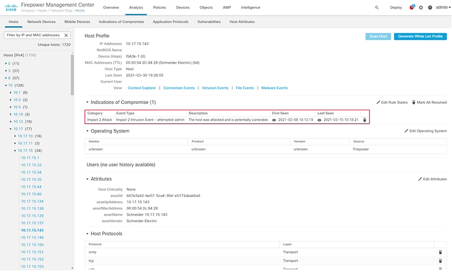
Hosts
Each IP address detected by the FTD device is logged and FMC displays details about the entity, including any attributes sent from Cyber Vision and indicators of compromise (IoCs). In FMC, navigate to Analysis > Hosts > Network Map and choose an IP address from the Hosts menu on the left to view the details.
File Events
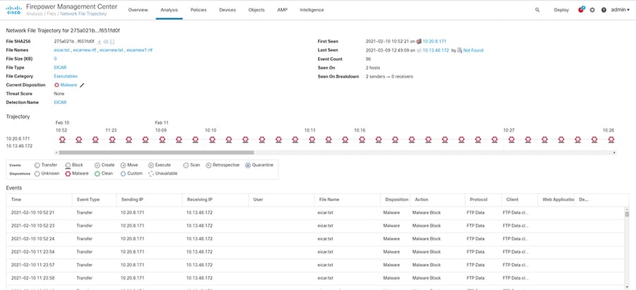
Much like connection and intrusion events, if a malware and file policy has been created, FMC shows an events list for activity matching the policy. In FMC, navigate to Analysis > Files > Malware Events or Analysis > Files > File Events to view the details of each event. In addition, FMC will show the file transfer details over time under Analysis > Files > Network File Trajectory.
Figure 12 FMC File Trajectory Analysis
SecureX
Cisco SecureX contains a wealth of information correlated for numerous sources to aid detection and analysis. After integrating FMC with SecureX, the SecureX dashboard will display events and metrics from FMC. Events can be reviewed and escalated as incidents.
Troubleshooting
Cyber Vision Network Sensor Placement in the Network
Providing the correct ERSPAN source and choosing an appropriate point in the traffic path for data ingestion is key for the Cyber Vision Sensor to provide needed visibility. For example, in ring topologies with several switches and end devices distributed around the ring, there is potential for missed traffic if the end device data does not flow through the switch with the Cyber Vision Sensor. Further, resiliency mechanisms such as the REP alternate port can change the traffic path and potentially bypass the switch with the Cyber Vision Sensor. Keeping these things in mind can help if expected device communications are not ingested by the Cyber Vision Sensor.
FTD CLI
The FTD CLI has many useful commands for checking statistics and other real-time configurations and metrics. The following commands can help in troubleshooting performance as well as Snort processing.
The show snort statistics command gives real-time counts of the Snort engine performance, such as packets that are passed or packets that are dropped because Snort is busy or down.
The system support trace command allows the user to specify traffic for debugging that is output to the CLI as Snort engine processes the traffic.
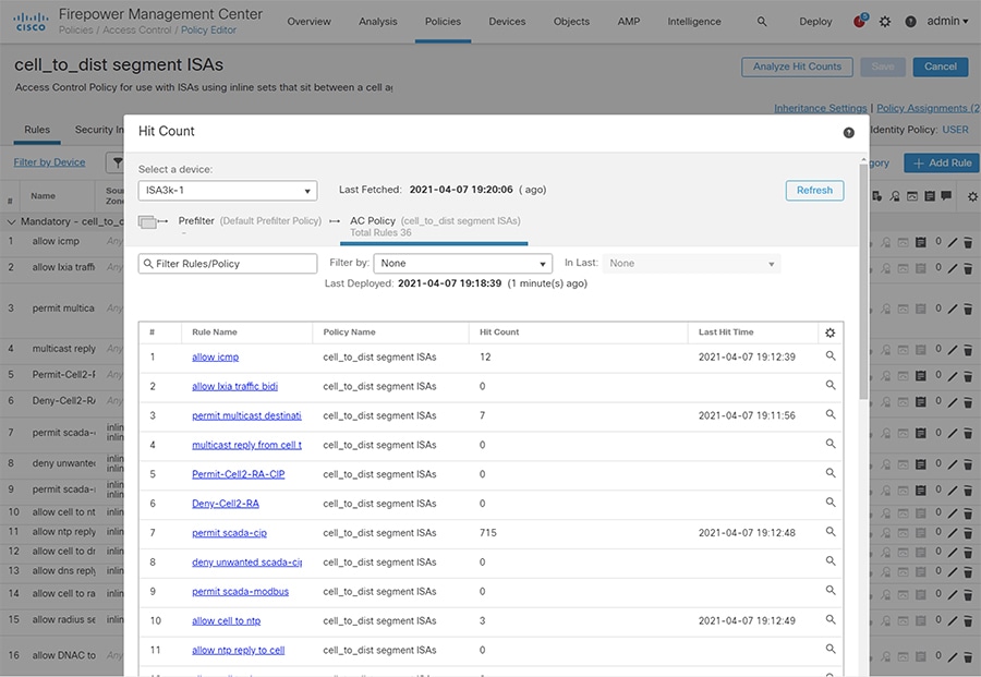
FMC Access Control Logging and Hit Count
Enabling logging for each access control rule provides a record of each allowed or blocked communication that the FTD devices processes and is useful for tuning access control rules. See Access Control Policy for details on configuring logging. In addition, the Analyze Hit Counts button on the access control Policy Editor page can help determine the efficacy of access control rules.
Figure 13 Access Control Policy Hit Count
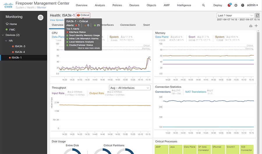
FMC Health Monitor
The FMC has system monitoring capabilities for itself as well as the FTD devices it manages. Resources such as CPU, memory, and disk are monitored for utilization over time and FMC will alarm when usage has exceeded a healthy threshold. In FMC, navigate to System > Health > Monitor and choose the necessary device to view the health statistics.
Appendix
Cisco Catalyst IE 3400 and IE 3300 Configuration Preparation for the Cyber Vision Sensor
ERSPAN
The Encapsulated Remote Switched Port Analyzer (ERSPAN) feature in Cisco IOS sends data to the Cisco Cyber Vision Sensor application within the switch. ERSPAN creates copy of specified source traffic from a port or VLAN and sends it to an IP address, making use of generic routing encapsulation (GRE) allowing it to traverse to a remote destination across the Layer 3 network. The Cisco Cyber Vision Sensor interface that captures traffic is given an IP address in order to receive the data sent from the ERSPAN instance on the switch. To configure the ERSPAN on the switch, enter the following commands in enable mode:
IOx
The IE 3400 and IE 3300 switches require a 4GB SD card to be used for IOx applications. To format the SD card, enter the following command in enable mode:
To enable IOx, enter the following commands in enable mode:
Port Configuration
The Cisco Cyber Vision Sensor application communicates over IP to the Cisco Cyber Vision Center, therefore at least one interface (SVI or physical) must be configured with an IP address that is able to communicate through the network to the Cisco Cyber Vision Center. A VLAN interface was used in this implementation:
In addition, the AppGigabitEthernet interface must be configured as a trunk to transfer data to and from the Cisco Cyber Vision Sensor application:
The Cisco IOS XE image for the IE 3400 can also run on the SD card alongside the Cyber Vision IOx application. For this configuration, do the following:
The argument 72 in the partition command is the storage percentage allocated to the IOx partition, and can be adjusted to suit your needs, however the Cyber Vision Sensor requires at least 2048 MB. The switch will automatically reload after running the partition command. After the switch has reloaded, the boot variable can be set to the image stored in SDFLASH and IOx can be activated for the Cyber Vision Sensor installation.
Cisco Catalyst 9300 Configuration Preparation for the Cyber Vision Sensor
ERSPAN
As with the IE 3400 and IE3000 switches, the Cisco Catalyst 9300 switch uses ERSPAN to copy traffic to the Cisco Cyber Vision Sensor application. To configure the ERSPAN on the switch, enter the following commands in enable mode:
IOx
The Cisco Catalyst 9300 switch requires a Solid State Drive (SSD) for IOx applications. For more information about installing the SSD, see: https://www.cisco.com/c/en/us/td/docs/switches/lan/catalyst9300/hardware/install/b_c9300_hig/b_c9300_hig_chapter_01010.html.
If the Cisco Catalyst 9300 is in a StackWise-480 configuration, the switch with the SSD must be in the active role. To format the SSD, enter the following command in enable mode:
To enable IOx, enter the following commands in enable mode:
Port Configuration
The Cisco Cyber Vision Sensor application communicates over IP to the Cisco Cyber Vision Center, therefore at least one interface (SVI or physical) must be configured with an IP address that is able to communicate through the network to the Cisco Cyber Vision Center. A VLAN interface was used in this implementation:
 Feedback