Cisco Cloud Network Automation Provisioner for the Microsoft Cloud Platform-Administrator Portal Guide, Release 2.1
Bias-Free Language
The documentation set for this product strives to use bias-free language. For the purposes of this documentation set, bias-free is defined as language that does not imply discrimination based on age, disability, gender, racial identity, ethnic identity, sexual orientation, socioeconomic status, and intersectionality. Exceptions may be present in the documentation due to language that is hardcoded in the user interfaces of the product software, language used based on RFP documentation, or language that is used by a referenced third-party product. Learn more about how Cisco is using Inclusive Language.
- Updated:
- August 10, 2016
Chapter: Managing Container Plans
- Viewing Summary Information about Containers and Tenant Administrators
- Viewing Summary Information about a Specific Container
- Deleting a Container
- Setting Up and Managing WAN Gateways
- Configuring and Managing Firewalls
- Understanding Firewall Creation
- Viewing Summary Information about a Firewall
- Viewing the Hierarchy of Information on the Firewall Tab
- Configuring a Firewall
- Changing a Policy Map for a Service Policy
- Adding a New Class Map
- Changing a Class Map
- Creating a New Network Access Control List
- Changing an Access List
- Creating a New Object Group
- Changing an Object Group
Managing Container Plans
The Service Provider administrator can use the Cisco CNAP Admin Portal to:
- Display summary information about containers and tenant administrators
- Delete a container
- Display and modify gateway information about a container:
–![]() Look at information about a gateway.
Look at information about a gateway.
–![]() Add a gateway (you cannot configure a WAN Gateway until a tenant has created a container and the container is active).
Add a gateway (you cannot configure a WAN Gateway until a tenant has created a container and the container is active).
–![]() View summary information about a firewall.
View summary information about a firewall.
–![]() View the hierarchy of information on the Firewall tab.
View the hierarchy of information on the Firewall tab.
–![]() Set up a tenant perimeter firewall.
Set up a tenant perimeter firewall.
–![]() Change the policy map for a service policy.
Change the policy map for a service policy.
–![]() Create a new network Access Control List (ACL).
Create a new network Access Control List (ACL).

Note![]() Since Cisco CNAP is also pushing configurations for the automation of work flows on devices, certain precautions need to be followed when manually configuring devices to avoid disrupting Cisco CNAP-based automation. Changing configurations pushed from Cisco CNAP will cause the automated provisioning system to malfunction, which in some cases could cause all automated provisioning to stop until the error conditions are manually remediated. In general on the data center provider edge, all configurations under the tenant VRFs pushed by Cisco CNAP should not be edited or changed, including sub-interfaces and routing. Similarly on the Cisco APIC, the Cisco APIC tenants configured by Cisco CNAP should only be changed by Cisco CNAP. Any configurations pushed by Cisco CNAP should not be manually edited. For more information, see Installing Cisco Cloud Network Automation Provisioner for the Microsoft Cloud Platform, Release 2.1.
Since Cisco CNAP is also pushing configurations for the automation of work flows on devices, certain precautions need to be followed when manually configuring devices to avoid disrupting Cisco CNAP-based automation. Changing configurations pushed from Cisco CNAP will cause the automated provisioning system to malfunction, which in some cases could cause all automated provisioning to stop until the error conditions are manually remediated. In general on the data center provider edge, all configurations under the tenant VRFs pushed by Cisco CNAP should not be edited or changed, including sub-interfaces and routing. Similarly on the Cisco APIC, the Cisco APIC tenants configured by Cisco CNAP should only be changed by Cisco CNAP. Any configurations pushed by Cisco CNAP should not be manually edited. For more information, see Installing Cisco Cloud Network Automation Provisioner for the Microsoft Cloud Platform, Release 2.1.
Viewing Summary Information about Containers and Tenant Administrators
The Containers tab under the Tenants tab displays a list of all the tenant containers currently managed by Cisco CNAP, as shown on the Tenants Tab—Containers screen.
Figure 5-1 Tenants Tab Screen—Containers
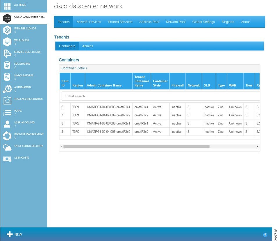
Each container row visible on the Tenants tab shows the following information:
- Cont ID—The ID of the container.
- Region—Name of the region to which the container is associated.
- Admin Container Name—Descriptive name of the container in the Admin Portal.
- Tenant Container Name—Descriptive name of the container in the Tenant Portal.
- Container State—The current state of the container:
- Firewall—The status of all Firewall Services associated with a particular container.
- Network—Total number of networks in the container.
- SLB—The status of all Load Balancer Services associated with a particular container.
- Type—The type of container, which in the current release is only Zinc.
- WAN—The status of each of the WAN Gateway Services (MPLS VPN, Site-to-Site and Remote Access VPN, or Internet Access) associated with a particular container.
- Tiers—The number of tiers currently configured in the container.
- Created On:—Displays the date and time when the container was created.
- Modified On:—Displays the date and time when the container was last modified.
The Admins tab under the Tenants tab displays a list of all the Tenant Administrators, as shown on the Tenants Tab—Admins screen.
Figure 5-2 Figure Tenants Tab Screen—Admins
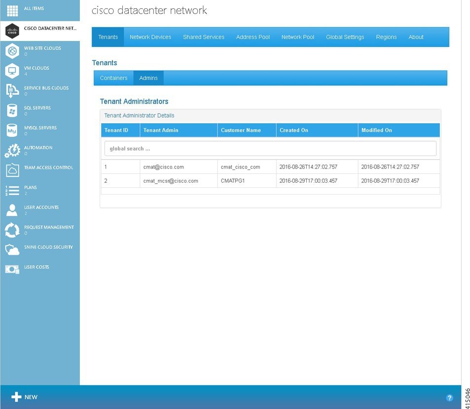
Each tenant row visible on the Tenants tab shows the following information:
- Tenant ID—The ID of the Tenant Administrator.
- Tenant Admin—The login credential of the Tenant Administrator.
- Customer Name—The name of the customer.
- Created On:—Displays the date and time when the Tenant Administrator was created.
- Modified On:—Displays the date and time when the Tenant Administrator was last modified.
Viewing Summary Information about a Specific Container
Step 1![]() To display summary information about a specific container, on the Tenants tab click on the row with the container you want to view, as shown in the following screen.
To display summary information about a specific container, on the Tenants tab click on the row with the container you want to view, as shown in the following screen.
Figure 5-3 Tenants Tab—Container Selected

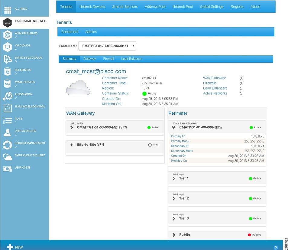
You see the Tenants Summary screen.
Figure 5-4 Tenants Summary Screen

The Tenants Summary screen displays a list of the WAN Gateway services configured in the container (only MPLS VPN in current release) and a list of all the perimeter network services configured in the container (firewall, tiers, DMZ, etc.).
Specific information above the WAN Gateway and Perimeter tables includes:
- Container Name:—Displays the container name.
- Container Type:—Displays the container type name.
- Region:—Displays the Region name.
- Status:—Displays the container status. The icons indicate (icons are only meaningful on initial configuration as status is not routinely monitored):
–![]() Yellow—Container state is Creating.
Yellow—Container state is Creating.
- Created On:—Displays the date and time when the container was created.
- Modified On:—Displays the date and time when the container was last modified.
- WAN Gateways—Displays the total count of WAN gateways. For example, if MPLS VPN and Site-to-Site were part of the container, the displayed text would be WAN Gateways (2). The icon indicates the status of the WAN Gateway(s): Green, Red, and Gray (icons are only meaningful on initial configuration as status is not routinely monitored).
- Firewalls—Displays the total count of firewalls. For example, if one firewall was part of the container, the displayed text would be Firewalls (1). The icon indicates the status of the firewall(s): Green, Red, and Gray (icons are only meaningful on initial configuration as status is not routinely monitored).
- Load Balancers—Displays the total count of Load Balancers.
- Active Networks—Displays the total count of active networks configured on the container. For example, if there were five total networks, the displayed text would be Active Networks (5).
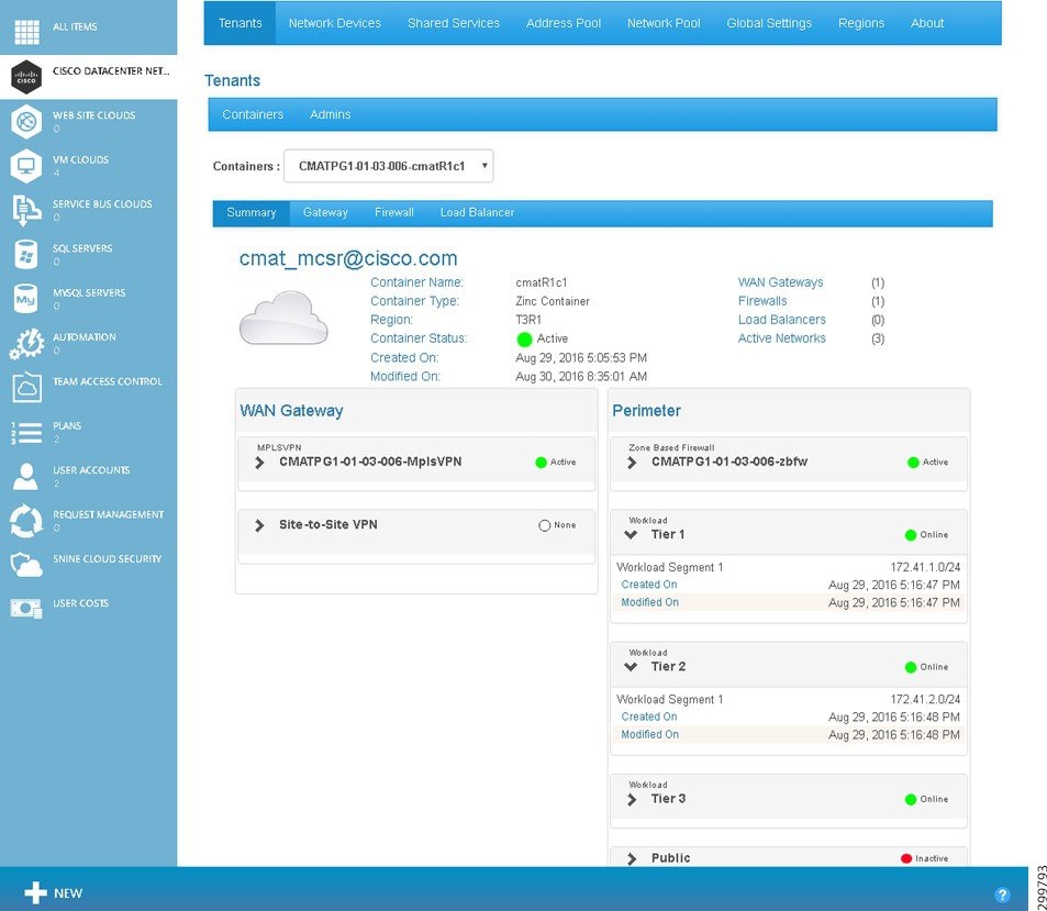
You can collapse and expand the table information using the triangles, as shown in the following sample screens for the MPLS VPN WAN Gateway, Perimeter Firewall, and Perimeter Tier 1.
Figure 5-5 Summary Tab—WAN Gateway MPLS VPN Details

Using MPLS VPN as an example, the information in the WAN Gateway table includes:
- MPLSVPN and name—Gateway type, name of the gateway, and an icon to indicate the status of the VPN (icons are only meaningful on initial configuration as status is not routinely monitored).
- Import RT—Displays the RT based on your network design.
- Export RT—Displays the RT based on your network design.
- Route Descriptor—Displays the descriptor based on your network design.
- VRF—Generated by Cisco CNAP based on the abbreviation of the container ID.
- Primary IP—External PE IP Address in dotted format.
- Secondary IP—External PE IP Address in dotted format.
- Mask—External PE Mask in dotted format
- Created On:—Displays the date and time when the WAN Gateway was created.
- Modified On:—Displays the date and time when the WAN Gateway was last modified.
Information in the Perimeter table is based on the currently selected Cloud Service and includes information about firewalls and tiers (in the current release, public for backups and recovery for DMZ are not used).
Figure 5-6 Summary Tab—Perimeter Firewall Details
Using Zone Based Firewall as an example, the information in the Perimeter table includes:
- Zone Based Firewall and name—Firewall type, name of the firewall, and an icon to indicate the status of the firewall (icons are only meaningful on initial configuration as status is not routinely monitored).
- Primary IP—External PE IP Address
- Primary Mask—External PE Mask
- Secondary IP—External PE IP Address
- Secondary Mask—External PE Mask
- Created On:—Displays the date and time when the firewall was created in the form.
- Modified On:—Displays the date and time when the firewall was last modified.
Figure 5-7 Summary Tab—Perimeter Tier Details
Deleting a Container
Note![]() When you delete a container, all information about the container is deleted from the Cisco CNAP database and none of the deleted information can be recovered.
When you delete a container, all information about the container is deleted from the Cisco CNAP database and none of the deleted information can be recovered.
Step 1![]() To delete a container, on the Tenants tab click on the row with the container you want to delete, as shown in the following screen.
To delete a container, on the Tenants tab click on the row with the container you want to delete, as shown in the following screen.
Figure 5-8 Tenants Tab—Container Selected
You see the Tenants Summary screen.
Figure 5-9 Tenants Summary Screen
Step 2![]() You can use the Containers: pull-down menu to select a different container to delete. To delete the selected container, at the bottom of the screen click Remove.
You can use the Containers: pull-down menu to select a different container to delete. To delete the selected container, at the bottom of the screen click Remove.
You see a screen asking you to confirm the deletion, as shown in the following screen.
Figure 5-10 Confirm Container Deletion
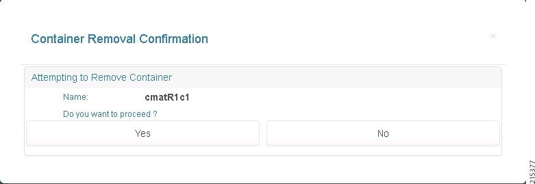
Step 3![]() Click Yes to delete the container or No to cancel the deletion.
Click Yes to delete the container or No to cancel the deletion.
Setting Up and Managing WAN Gateways
Tenants can access their cloud networks via a WAN. This section describes the provisioning of WAN Gateways for tenant containers, which in this release includes one option:
- Automated provisioning of MPLS L3VPN-based access for the tenant, including provisioning of the Data Center WAN Edge/PE.
Note![]() For single CSR containers, which are not supported in this release, there is an option for no automated provisioning of the Data Center PE. A VLAN-based hand-off from the Data Center PE to the Data Center Fabric/network is provisioned for each tenant.
For single CSR containers, which are not supported in this release, there is an option for no automated provisioning of the Data Center PE. A VLAN-based hand-off from the Data Center PE to the Data Center Fabric/network is provisioned for each tenant.
On the gateway tab screen, you can:
You should not configure a WAN Gateway until a tenant has created a container and the container is active. Check that the container is created and shown as active before provisioning the WAN Gateway.
Step 1![]() To display gateway information about a specific container, on the Tenants tab click on the row with the container you want to view, as shown in the following screen.
To display gateway information about a specific container, on the Tenants tab click on the row with the container you want to view, as shown in the following screen.
Figure 5-11 Tenants Tab—Container Selected Screen
You see the Tenants Summary screen.
Figure 5-12 Tenants Summary Screen
You see the Tenant Gateway screen.
Figure 5-13 Tenant Gateway Screen
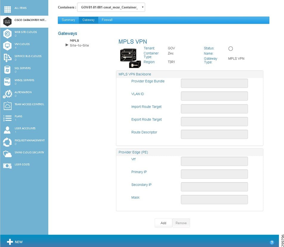
The screen displays the following information:
- Container Name:—Displays the container name.
- Container Type:—Displays the container type name, which in the current release is limited to Zinc.
- Region:—Displays the Region name.
- Status:—Displays the WAN Gateway status. The icons indicate (icons are only meaningful on initial configuration as status is not routinely monitored):
–![]() Green—WAN Gateway is Active.
Green—WAN Gateway is Active.
–![]() Red—WAN Gateway is Inactive.
Red—WAN Gateway is Inactive.
–![]() Yellow—WAN Gateway state is Creating.
Yellow—WAN Gateway state is Creating.
- Name:—Displays the name in the form <abbreviation>-mpls-vpn.
- Gateway Type:—MPLS VPN
- Description:—Descriptive name.
The MPLS VPN Backbone and PE fields are described in the next section on Setting Up a WAN Gateway.
Understanding the Difference Between Auto-provisioning and Manually Provisioning WAN Gateways
Note![]() This distinction only applies to single CSR containers, which are not supported in this release.
This distinction only applies to single CSR containers, which are not supported in this release.
During container creation, you can specify whether you want to auto-provision WAN Edge/PE. If you select Autoprovision WAN Edge/PE, then during WAN setup you enter MPLS VPN information, such as route targets and route descriptor, and Cisco CNAP automatically selects a VLAN from the infrastructure pool and uses cloud settings that you defined for the Cisco APIC vPC information to set up the WAN Gateways in the plan.
If your network does not include PE equipment (e.g., Cisco ASRs), you can manually provision the WAN gateways in a plan. During container creation, do not select Autoprovision WAN Edge/PE. Then during set up of WAN Gateways, you can specify the VLAN that will be used on the vPC to connect to private network service, as well as the external PE A and PE B IP addresses.

All gateways set up in the plan will be provisioned in the same way, either automatically or manually.
Setting Up a WAN Gateway
Note![]() You cannot configure a WAN Gateway until a tenant has created a container and the container is active.
You cannot configure a WAN Gateway until a tenant has created a container and the container is active.
To set up a WAN Gateway, you specify WAN Gateway settings as appropriate for the VPN access methods you select:
Setting up a MPLS WAN Gateway
The information you enter is different depending on whether during container creation you specified you wanted Cisco CNAP to Autoprovision WAN Edge/PE. (This distinction only applies to single CSR containers, which are not supported in this release.)
To set up a MPLS WAN Gateway for a container:
Step 1![]() On the Tenants tab click on the row with the container for which you want to set up a MPLS WAN Gateway, as shown in the following screen.
On the Tenants tab click on the row with the container for which you want to set up a MPLS WAN Gateway, as shown in the following screen.
Figure 5-14 Tenants Tab—Container Selected Screen
You see the Tenants Summary screen.
Figure 5-15 Tenants Summary Screen
Note![]() The specific Tenant Gateway screen you see depends on whether or not during container creation you specified Autoprovision WAN Edge/PE.(Note: This distinction only applies to single CSR containers, which are not supported in this release.)
The specific Tenant Gateway screen you see depends on whether or not during container creation you specified Autoprovision WAN Edge/PE.(Note: This distinction only applies to single CSR containers, which are not supported in this release.)
Setting up an Auto-provisioned WAN Edge/PE
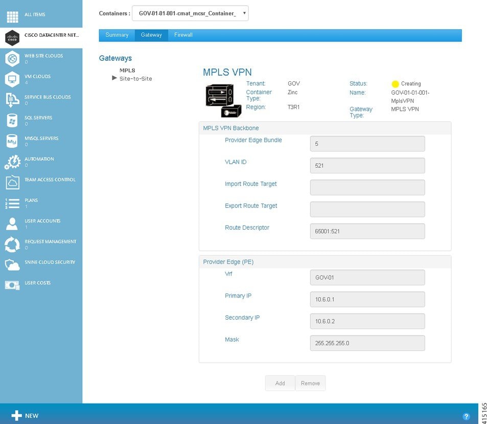
Figure 5-16 Tenant Gateway Screen—Auto-provision Provider Edge
The route descriptor is auto-generated depending on the value of the RouteDescriptorPrefix global system setting, as well as the VLAN used. The RouteDescriptorPrefix setting accepts either:
–![]() PeBundle—Uses the PE Bundle for this region.
PeBundle—Uses the PE Bundle for this region.
–![]() PeAutoSystemNumber—Uses the BGP Provider Edge AS number for this cloud.
PeAutoSystemNumber—Uses the BGP Provider Edge AS number for this cloud.
The following screen shows a gateway being created with auto-populated values.
Setting up a Manually Provisioned WAN Edge/PE
Note![]() This distinction only applies to single CSR containers, which are not supported in this release.
This distinction only applies to single CSR containers, which are not supported in this release.
Figure 5-18 Tenant Gateway Screen—Manual Provision Provider Edge
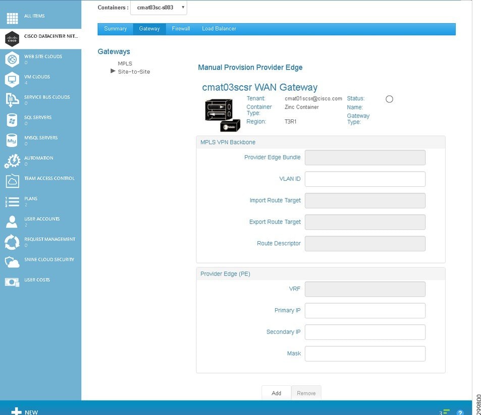
a.![]() Complete the modifiable fields to add the gateway:
Complete the modifiable fields to add the gateway:
Note![]() Modifiable fields when manually-provisioning WAN Edge/PE are VLAN ID, Primary IP, Secondary IP, and Mask, which are noted in bold below.
Modifiable fields when manually-provisioning WAN Edge/PE are VLAN ID, Primary IP, Secondary IP, and Mask, which are noted in bold below.
–![]() Provider Edge Bundle—The bundled interface on the ASR, the same as in the Global settings for clouds, MPLS Network, Primary PE ACI L2 Attachment.
Provider Edge Bundle—The bundled interface on the ASR, the same as in the Global settings for clouds, MPLS Network, Primary PE ACI L2 Attachment.
Note![]() The following fields are not displayed when manually provisioning WAN Edge/PE. The SP administrator should consult with the Microsoft WAP PE administrator to provision the tenant network into the correct L3VPN or other private network for the tenant and agree on the VLAN used for the hand-off of tenant traffic to the cloud data center.
The following fields are not displayed when manually provisioning WAN Edge/PE. The SP administrator should consult with the Microsoft WAP PE administrator to provision the tenant network into the correct L3VPN or other private network for the tenant and agree on the VLAN used for the hand-off of tenant traffic to the cloud data center.
–![]() Import Route Target—RT based on the network design.
Import Route Target—RT based on the network design.
–![]() Export Route Target—RT based on the network design.
Export Route Target—RT based on the network design.
–![]() Route Descriptor—Descriptor based on the network design.
Route Descriptor—Descriptor based on the network design.
–![]() VRF—Generated by Cisco CNAP based on the abbreviation of the container ID.
VRF—Generated by Cisco CNAP based on the abbreviation of the container ID.
–![]() Primary IP —Enter the external PE IP Address in dotted format.
Primary IP —Enter the external PE IP Address in dotted format.
–![]() Secondary IP —Enter the external PE IP Address in dotted format.
Secondary IP —Enter the external PE IP Address in dotted format.
–![]() Mask —Enter the external PE Mask in dotted format.
Mask —Enter the external PE Mask in dotted format.
Note![]() Based on the PE IP address and subnet mask you specify, Cisco CNAP automatically provisions the Cisco CSR 1000V interface IP and HSRP address.
Based on the PE IP address and subnet mask you specify, Cisco CNAP automatically provisions the Cisco CSR 1000V interface IP and HSRP address.
b.![]() When you are finished, click the Add button.
When you are finished, click the Add button.
Setting up a Site-to-Site VPN
Step 1![]() Click the Gateway tab, then under Gateways, click Site-to-Site. You see the following screen.
Click the Gateway tab, then under Gateways, click Site-to-Site. You see the following screen.
Figure 5-19 Site-to-Site VPN Screen

Step 2![]() Complete the following fields:
Complete the following fields:
–![]() Encryption—Encryption used for the IKE proposal; used to ensure the secrecy of data during traffic flow: AES, DES, or Triple DES.
Encryption—Encryption used for the IKE proposal; used to ensure the secrecy of data during traffic flow: AES, DES, or Triple DES.
–![]() Hash—Specifies the hash algorithm within an IKE policy; used to authenticate data during traffic flow: MD5, SHA, or SHA256.
Hash—Specifies the hash algorithm within an IKE policy; used to authenticate data during traffic flow: MD5, SHA, or SHA256.
–![]() Keep Alive—Number of seconds during which traffic is not received from the peer before keep-alive messages are sent if there is data traffic to send.
Keep Alive—Number of seconds during which traffic is not received from the peer before keep-alive messages are sent if there is data traffic to send.
–![]() Retry—Number of seconds between keep-alive packet retries if the keep-alive message fails.
Retry—Number of seconds between keep-alive packet retries if the keep-alive message fails.
–![]() Group—Specify which Diffie-Hellman Modulus Group to use.
Group—Specify which Diffie-Hellman Modulus Group to use.
–![]() Method—Pre-Shared Key: Allow for a secret key to be shared between two peers for mutual authentication prior to tunnel activation.
Method—Pre-Shared Key: Allow for a secret key to be shared between two peers for mutual authentication prior to tunnel activation.
–![]() Shared Key—The shared secret for authentication. The shared key must be configured and equal at each peer or the IKE SA cannot be established.
Shared Key—The shared secret for authentication. The shared key must be configured and equal at each peer or the IKE SA cannot be established.
–![]() esp-des—ESP with the 56-bit Data Encryption Standard (DES) encryption algorithm (no longer recommended).
esp-des—ESP with the 56-bit Data Encryption Standard (DES) encryption algorithm (no longer recommended).
–![]() esp-3des—ESP with the 168-bit DES encryption algorithm (3DES or Triple DES) (no longer recommended).
esp-3des—ESP with the 168-bit DES encryption algorithm (3DES or Triple DES) (no longer recommended).
–![]() esp-null—Null encryption algorithm.
esp-null—Null encryption algorithm.
–![]() esp-aes—SP with the 128-bit Advanced Encryption Standard (AES) encryption algorithm.
esp-aes—SP with the 128-bit Advanced Encryption Standard (AES) encryption algorithm.
–![]() esp-aes-192—SP with the 192-bit Advanced Encryption Standard (AES) encryption algorithm.
esp-aes-192—SP with the 192-bit Advanced Encryption Standard (AES) encryption algorithm.
–![]() esp-aes-256—SP with the 256-bit Advanced Encryption Standard (AES) encryption algorithm.
esp-aes-256—SP with the 256-bit Advanced Encryption Standard (AES) encryption algorithm.
–![]() esp-md5-hmac—ESP with the MD5 (HMAC variant) authentication algorithm (no longer recommended).
esp-md5-hmac—ESP with the MD5 (HMAC variant) authentication algorithm (no longer recommended).
–![]() esp-sha-hmac—ESP with the SHA (HMAC variant) authentication algorithm.
esp-sha-hmac—ESP with the SHA (HMAC variant) authentication algorithm.
–![]() ah-md5-hmac—AH with the MD5 (Message Digest 5) (an HMAC variant) authentication algorithm (no longer recommended).
ah-md5-hmac—AH with the MD5 (Message Digest 5) (an HMAC variant) authentication algorithm (no longer recommended).
–![]() ah-sha-hmac—AH with the SHA (Secure Hash Algorithm) (an HMAC variant) authentication algorithm.
ah-sha-hmac—AH with the SHA (Secure Hash Algorithm) (an HMAC variant) authentication algorithm.
Step 3![]() When you are finished, click Add Tunnel.
When you are finished, click Add Tunnel.
Removing a Gateway
On the Tenants tab, click on the row with the container whose WAN Gateway you want to remove, then on the Gateway tab, click Remove.
Configuring and Managing Firewalls
- View summary information about a firewall
- View the hierarchy of information on the Firewall tab
- Configure a firewall
- Change the policy map for a service policy
- Add a new class map
- Change a class map
- Create a new network Access Control List (ACL)
- Change an Access List
- Create a new object group
- Change an object group
Understanding Firewall Creation
A firewall is created by default the moment you create a WAN Gateway in the Zinc container and a default policy is applied that allows inside to outside traffic, but restricts outside to inside traffic. The SP administrator can view and manage tenant firewalls, depending on the agreement with the tenant (e.g., you might do it as a managed service or while troubleshooting a customer reported problem). Each Tier is considered a zone, as is the Layer 3 VPN as well as any other external access such as Site-to-Site VPN, Internet access, etc. The Firewall tab will not display any information until the WAN Gateway has been provisioned, since there is no point in showing how traffic is going to be regulated if the tenant cannot access the container from the “outside”.
For detailed information on the base firewall configuration, see: Cisco Cloud Architecture for the Microsoft Cloud Platform: Zinc Container Configuration Guide, Release 1.0
http://www.cisco.com/c/en/us/td/docs/solutions/Service_Provider/CCAMCP/1-0/IaaS_Zinc_Config/CCAMCP1_IaaS_Zinc_Config.html
Viewing Summary Information about a Firewall
Step 1![]() To display firewall information about a specific container, on the Tenants tab click on the row with the container you want to view, as shown in the following screen.
To display firewall information about a specific container, on the Tenants tab click on the row with the container you want to view, as shown in the following screen.
Figure 5-20 Tenants Tab Screen—Container Selected
You see the Tenants Summary screen.
Figure 5-21 Tenants Summary Screen
Step 2![]() Click the Firewall tab.
Click the Firewall tab.
You see the Tenant Firewall screen.
Figure 5-22 Tenant Firewall Screen
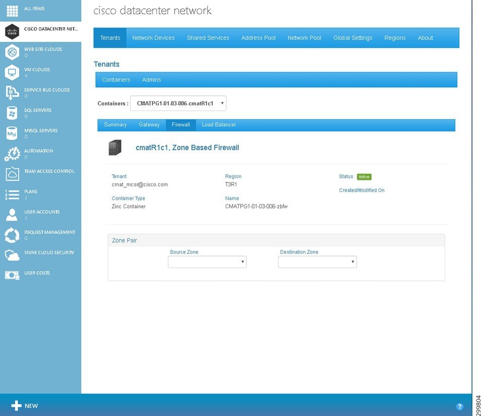
The screen displays the following information:
- Tenant:—Displays the tenant name.
- Container Type:—Displays the container type instance name.
- Hosting Cloud:—Displays the Hosting Cloud name.
- Modified:—Displays the date and time when the firewall was last modified in the form mm-dd-yyyy hh:mm:ss.
- Status:—Displays the firewall status. The icons indicate (icons are only meaningful on initial configuration as status is not routinely monitored):
–![]() Yellow—Firewall state is Creating.
Yellow—Firewall state is Creating.
- Name:—Displays the name in the form < abbreviation >-fw.
- Created:—Displays the date and time when the firewall was created in the form mm-dd-yyyy hh:mm:ss.
- Zone Pair—Source Zone and Destination Zone are the zones between which the firewall is configured.
Note![]() In rare instances, the retrieval of Zone Pairs may take longer than approximately 20 seconds, in which case you will see an error message. Dismiss the error message and refresh the screen.
In rare instances, the retrieval of Zone Pairs may take longer than approximately 20 seconds, in which case you will see an error message. Dismiss the error message and refresh the screen.
Viewing the Hierarchy of Information on the Firewall Tab
You use the Firewall Tab to view the various layers of information about firewalls, including:
Note![]() To change the Policy Map associated with a Source and Destination Zone pair, you have to define a new Policy Map, which replaces the existing one.
To change the Policy Map associated with a Source and Destination Zone pair, you have to define a new Policy Map, which replaces the existing one.
- Class Maps in a Policy Map
- Access Lists within a Class Map
- Rules in an Access List
- Object Groups of a Rule
Note![]() You can view the list of all Object Groups, but you cannot view or edit the details of any specific Object Group.
You can view the list of all Object Groups, but you cannot view or edit the details of any specific Object Group.
To display the various layers of information about a firewall:
Step 1![]() On the Firewall tab screen, use the Source Zone: and Destination Zone: pull-down menus to select the relevant zones, as shown in the following screens.
On the Firewall tab screen, use the Source Zone: and Destination Zone: pull-down menus to select the relevant zones, as shown in the following screens.
Figure 5-23 Firewall Source Zone Pull-down Menu Screen
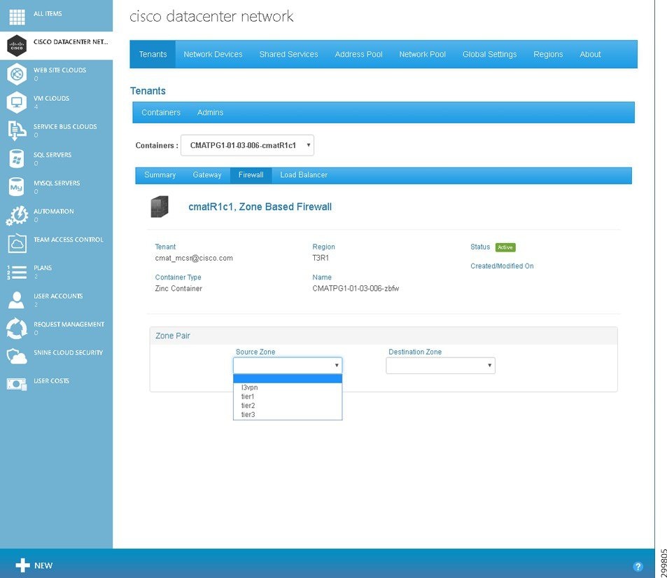
Figure 5-24 Firewall Destination Zone Pull-down Menu Screen

After you select the Source and Destination Zones, the screen populates with a variety of information, as shown in the following screen.
Figure 5-25 Firewall Zones Selected Screen—Detailed Firewall Information Displayed
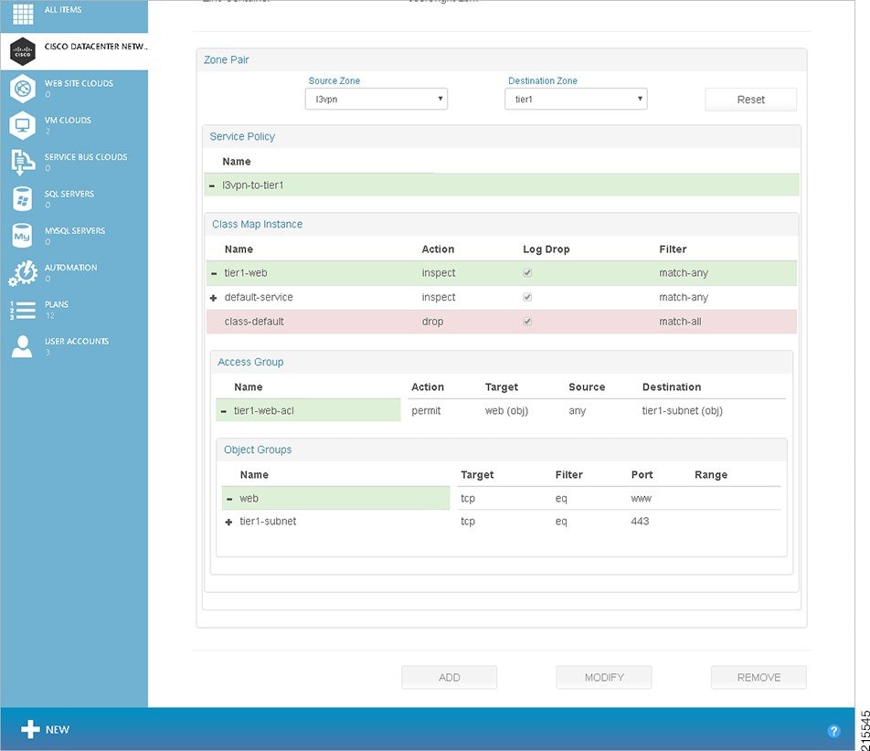
The various operations you can perform on this screen are described in the following section, Configuring a Firewall.
Step 2![]() If you click an element on the screen to bring it into focus, it changes to blue. For the element in focus:
If you click an element on the screen to bring it into focus, it changes to blue. For the element in focus:
- The Remove button de-couples the entity in focus, for example the Class Map Instance tier1-web, from the parent entity marked, for example the Policy Map l3vpn-to-tier1 for the Service Policy.
The Remove button may be used to remove a:
–![]() Class Map Instance from a Policy Map
Class Map Instance from a Policy Map
–![]() Access List from a Class Map
Access List from a Class Map
Note![]() In the current release, Cisco CNAP allows and requires you to associate only one Policy Map with any given zone pair. Consequently, the Remove button is deactivated when you drill down to the Policy Map, but not further.
In the current release, Cisco CNAP allows and requires you to associate only one Policy Map with any given zone pair. Consequently, the Remove button is deactivated when you drill down to the Policy Map, but not further.
Configuring a Firewall
Note![]() You can only configure a firewall after a tenant has created a container and the Admin has created a WAN Gateway. The firewall is automatically created with a base configuration during container creation. When the WAN gateway is created, another firewall zone is created for the WAN edge. For more information, see Understanding Firewall Creation.
You can only configure a firewall after a tenant has created a container and the Admin has created a WAN Gateway. The firewall is automatically created with a base configuration during container creation. When the WAN gateway is created, another firewall zone is created for the WAN edge. For more information, see Understanding Firewall Creation.
Firewalls are configurable on a per-Tier basis. You configure one firewall per container (not per tier) and you specify policy rules between zones. Firewall policies are specified between each of the workload Tiers and outside interfaces and in each direction independently. That is, a policy needs to be specified for L3VPN to Tier 1 and Tier 1 to L3VPN, and so on for each tier.
To configure a firewall for a container:
Step 1![]() On the Tenants tab, click the row with the container for which you want to configure a firewall, as shown in the following screen.
On the Tenants tab, click the row with the container for which you want to configure a firewall, as shown in the following screen.
Figure 5-26 Tenants Tab Screen—Container Selected
You see the Tenants Summary screen.
Figure 5-27 Tenants Summary Screen
Step 2![]() Click the Firewall tab.
Click the Firewall tab.
You see the Tenant Firewall screen.
Figure 5-28 Tenant Firewall Screen
Step 3![]() Use the Source Zone: and Destination Zone: pull-down menus to select the relevant zones. After you select the zones, the screen populates with a variety of information, as shown in the following screen.
Use the Source Zone: and Destination Zone: pull-down menus to select the relevant zones. After you select the zones, the screen populates with a variety of information, as shown in the following screen.
Figure 5-29 Firewall Zones Selected Screen—Detailed Firewall Information Displayed
Step 4![]() To add a Policy Map, click the Policy Map under Service Policy, then click the Add button. You see the following screen.
To add a Policy Map, click the Policy Map under Service Policy, then click the Add button. You see the following screen.
Figure 5-30 Add Policy Map for Service Policy Screen
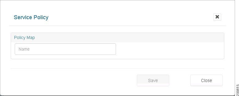
As you begin entering a name, the screen expands to display the following screen where you can associate class maps with the new Policy Map.
Figure 5-31 New Policy Map—Class Maps Screen
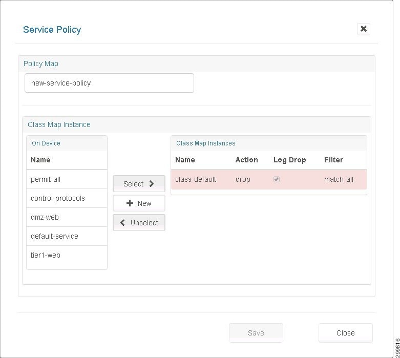
Step 6![]() Associate class maps with the new Policy Map:
Associate class maps with the new Policy Map:
- Name—Enter a descriptive name for the Policy Map.
- On Device—Lists all the Class Maps available on the device.
- Class Map Instances—Lists the class maps associated with this Policy Map.
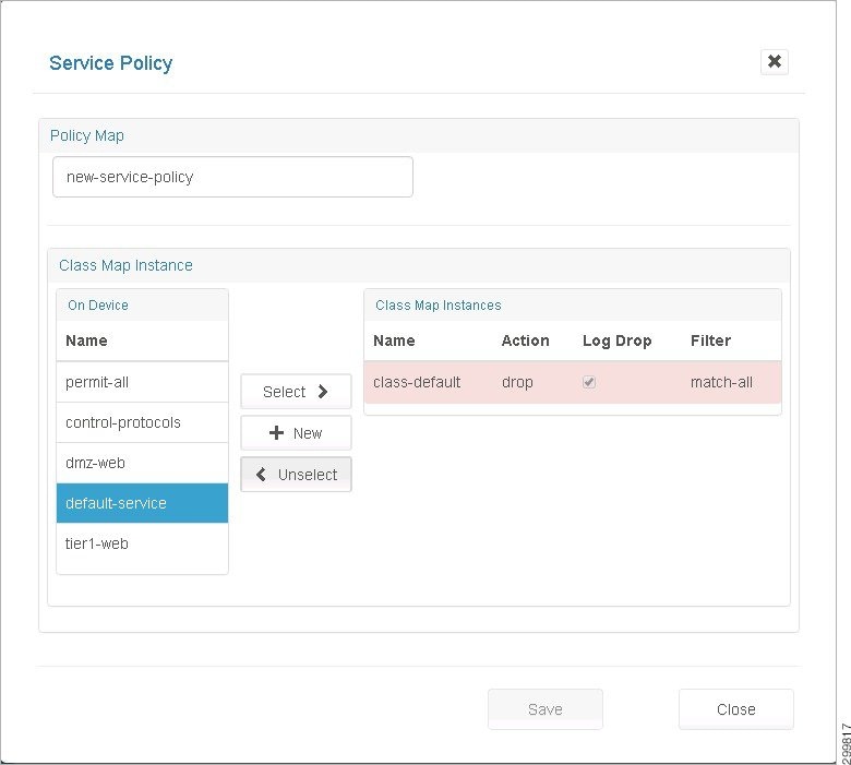
- Select>> button—Click to select one or more Class Maps available “On Device”'. Clicking Select associates them to the current Policy Map.
- <<Unselect button—Click to select one or more Class Map Instances associated with the current Service Policy. Clicking Unselect disassociates them from the current Policy Map.
- +New button—Click the + New button to create a new Class Map.
- Ordering the Class Maps—The Class Map Instances get added to the top of the list. You can reorder them by clicking <<Unselect and Select>> on the Class Maps in the desired order.
Note![]() The class-default shown in the following screen cannot be de-coupled from the policy.
The class-default shown in the following screen cannot be de-coupled from the policy.
Figure 5-32 Class Map Instance class-default Screen
Step 7![]() When you are finished, click Save.
When you are finished, click Save.
Changing a Policy Map for a Service Policy
Step 1![]() Click a Policy Map to select it (mark it blue).
Click a Policy Map to select it (mark it blue).
Step 2![]() Click the Modify button to display the Policy Map pop-up.
Click the Modify button to display the Policy Map pop-up.
Figure 5-33 Policy Map Pop-up Screen
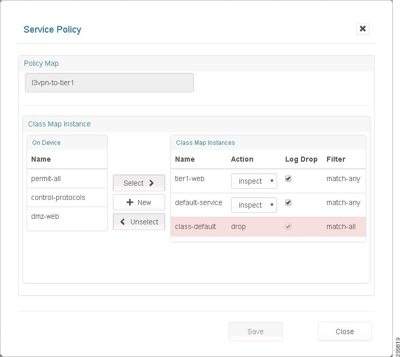
This is the same as the Create Service Policy page, but with the name field deactivated. You can click:
- Select>> to select Class Maps available on the device.
- <<Unselect to unselect Class Map Instances associated with the Policy Map.
- +New to create a new Class Map.
Adding a New Class Map
Step 1![]() Click + New in the Class Map Instance section on the Policy Map screen shown below.
Click + New in the Class Map Instance section on the Policy Map screen shown below.
Figure 5-34 Class Map Instance Screen—Click +New
Figure 5-35 New Class Map Instance Screen
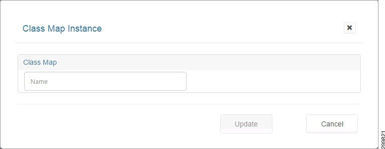
Step 2![]() In the Name field, enter a descriptive name for your new Class Map.
In the Name field, enter a descriptive name for your new Class Map.
This expands the screen to display the following screen.
Figure 5-36 New Class Map Instance Details Screen
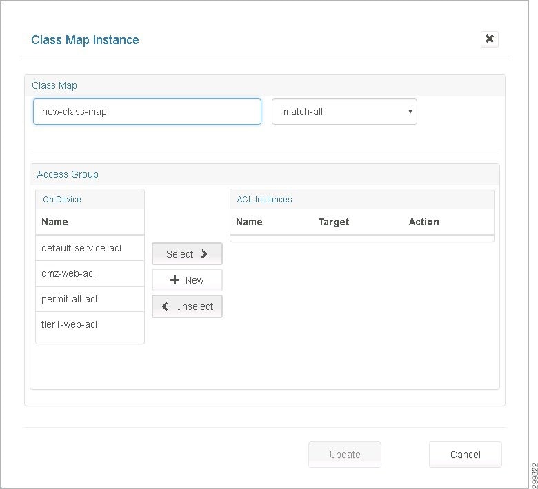
The fields on this screen are:
- match-all/match-any—This pull-down menu identifies the criteria used to match access groups in the map.
- On Device—Lists all the ACLs available for use on the device.
- ACL Instances—Lists the ACLs associated with this Class Map.
- Select>>, + New, and <<Unselect —These buttons work the same as on the Service Policy screen.
Step 3![]() When you are finished associating ACLs to this Class Map, click Update to return to the Service Policy screen.
When you are finished associating ACLs to this Class Map, click Update to return to the Service Policy screen.
Changing a Class Map
Step 1![]() Select the desired Class Map on the Firewall tab.
Select the desired Class Map on the Firewall tab.
Figure 5-37 Class Map Instance Screen
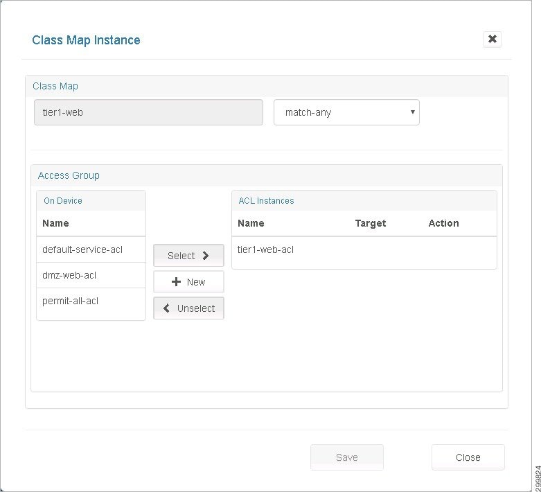
This screen is identical to the Create Class Map pop up, but with the Name field deactivated.
- Select>> ACLs from the list of ACLs available on the device.
- <<Unselect ACLs associated with the Class Map.
- Create a + New ACL on the device and have it associated with the Class Map.
Creating a New Network Access Control List
Step 1![]() Click New on the Class Map Instance screen shown above, which displays the Access Group screen shown below.
Click New on the Class Map Instance screen shown above, which displays the Access Group screen shown below.
Figure 5-38 Access Groups Screen
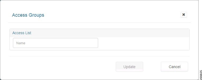
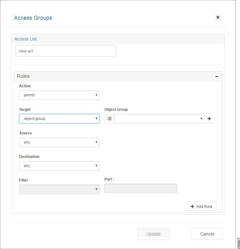
Step 2![]() When you enter a name for the Access List, the screen expands to display the Rules section. Since this is a new ACL, the screen expands in the Add Rule mode as shown below.
When you enter a name for the Access List, the screen expands to display the Rules section. Since this is a new ACL, the screen expands in the Add Rule mode as shown below.
Figure 5-39 Access Groups Details Screen
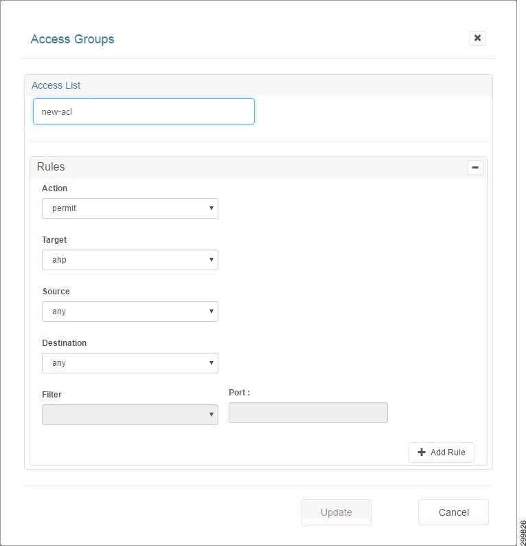
Step 3![]() The fields you can complete include:
The fields you can complete include:
- Action—Indicates weather traffic is permitted or denied by the rule.
- Target—A valid protocol or object group.
- Source—Network entity identified as the traffic source.
- Destination—Network entity identified as the traffic destination.
Step 4![]() If you select Object-Group in the drop-down menu for Target, the Source or Destination menus allow you to choose from object groups existing on the device or create new ones, as shown in the following screen.
If you select Object-Group in the drop-down menu for Target, the Source or Destination menus allow you to choose from object groups existing on the device or create new ones, as shown in the following screen.
Figure 5-40 Access Groups Screen—Object Group Selected
Step 5![]() Click the +Add Rule button to add the current rule being built to the ACL.
Click the +Add Rule button to add the current rule being built to the ACL.
Figure 5-41 Rule Added to ACL Screen
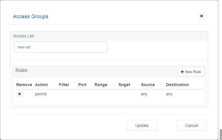
Step 6![]() Click +New Rule to add more rules.
Click +New Rule to add more rules.
Step 7![]() Click the Update button to exit the Add Rule mode and show the list of all rules in the ACL.
Click the Update button to exit the Add Rule mode and show the list of all rules in the ACL.
Changing an Access List
Step 1![]() Select the desired Access List on the Firewall tab.
Select the desired Access List on the Firewall tab.
Step 2![]() Click Modify to display the Access List pop-up screen, as shown below.
Click Modify to display the Access List pop-up screen, as shown below.
Figure 5-42 Access List Pop-up Screen
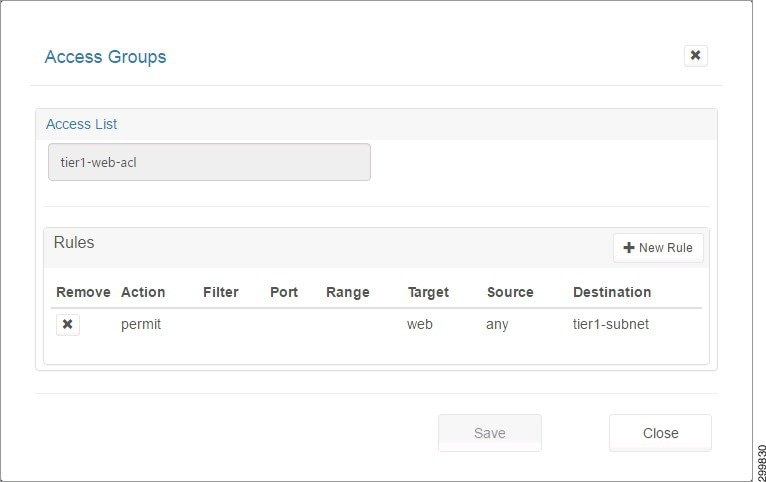
Step 3![]() You can add and remove rules as explained in Creating a New Network Access Control List.
You can add and remove rules as explained in Creating a New Network Access Control List.
Step 4![]() If you make any changes to the list of Rules, the Save button is activated and you can click it to save the changes.
If you make any changes to the list of Rules, the Save button is activated and you can click it to save the changes.
Creating a New Object Group
Step 1![]() Select the desired Access List on the Firewall tab.
Select the desired Access List on the Firewall tab.
Step 2![]() Click Modify to display the Access List pop-up screen, as shown in the following screen.
Click Modify to display the Access List pop-up screen, as shown in the following screen.
Figure 5-43 Access List Pop-up Screen
Step 3![]() Click the +New Rule button.
Click the +New Rule button.
On the Access Groups screen, the Target, Source, and Destination drop-down menus have an object-group option which when selected displays the Object Group: fields with drop-down menus with a list of compatible object groups and + buttons that launch a page where you can create a new compatible Object Group.
- The Object Group drop-down menu for Target would only show Service type Object Groups (groups of objects having the Target, filter, and port fields or having the Target and Range fields).
- The Object Group drop down for Source and Destination would only show Network type Object Groups (groups of objects having a Host field or having the Subnet and mask fields).
- The + buttons are contextual. Clicking the + button for the Target of the ACL Rule launches a page to create an Object Group with Service type objects.
- Clicking the + button for the Source or Destination of the ACL Rule launches a page to create an Object Group with Network type objects.
Step 4![]() Click the + button as shown in the following screen.
Click the + button as shown in the following screen.
Figure 5-44 Access Groups Screen—Object Group Selected
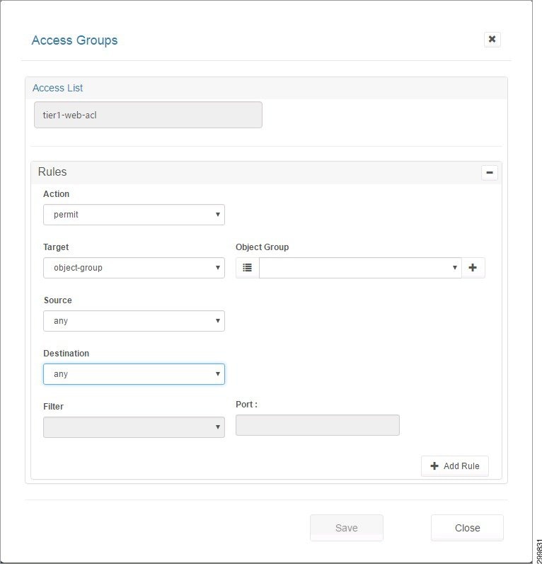
Figure 5-45 Object Group Screen
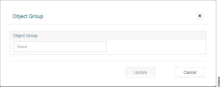
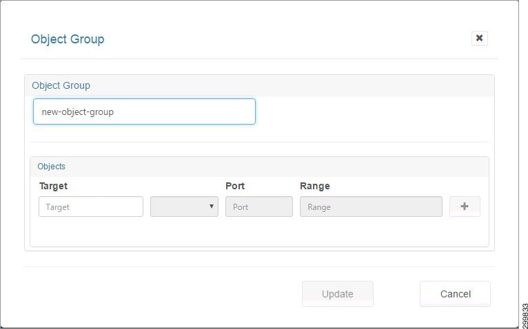
Step 5![]() When you enter a name, you see the Add Object screen, as shown below.
When you enter a name, you see the Add Object screen, as shown below.
Step 6![]() When you click a field, you see information about allowable values, as shown in the following screen.
When you click a field, you see information about allowable values, as shown in the following screen.
Figure 5-47 Add Object Screen—Possible Field Values Displayed
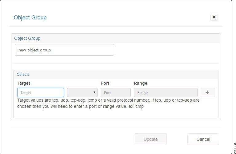
Step 7![]() You can enter information for the following fields:
You can enter information for the following fields:
- Target—A valid protocol {ahp, esp, gre, icmp, ip, tcp, udp, number [0,255]}.
- Filter—eq (equals), gt (greater than), or lt (less than). The Filter indicates the criteria to match packets based on the port number. If “filter” is present, then “port” must be present.
- Port—IP port [0,65535]
- Range—<port-number1>-<port-number2>. Must be entered from low to high, e.g., 20-90. Match only packets in the range of the port numbers.
Note![]() If “range” is present, the “filter” and “port” properties are ignored.
If “range” is present, the “filter” and “port” properties are ignored.
Step 8![]() You can create Network or Service type objects and click + to include the object in the group.
You can create Network or Service type objects and click + to include the object in the group.
A Group must be homogeneous; i.e., it must contain objects of only one type (Network or Service)
Step 9![]() When you click +, you see the following screen.
When you click +, you see the following screen.
Figure 5-48 Object Added to Group Screen
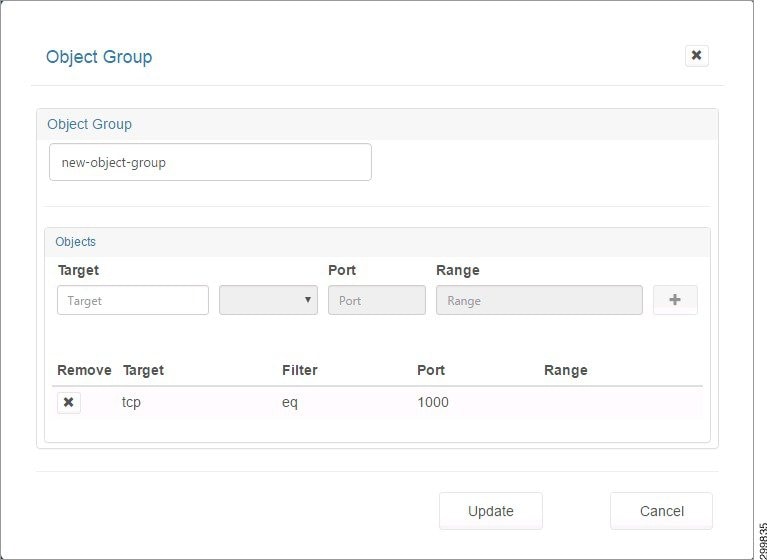
Step 10![]() Click the X under Remove to remove an object from the group.
Click the X under Remove to remove an object from the group.
Changing an Object Group
Step 1![]() On the screen shown below, select the object group you want to change, then click Modify.
On the screen shown below, select the object group you want to change, then click Modify.
Figure 5-49 Firewall Zones Selected Screen—Select Object Group
Figure 5-50 Modify Object Group Screen
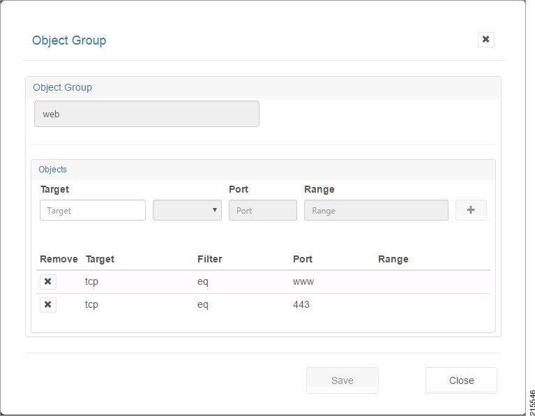
Step 2![]() You can enter information for the following fields:
You can enter information for the following fields:
- Target—A valid protocol {ahp, esp, gre, icmp, ip, tcp, udp, number [0,255]}.
- Filter—eq (equals), gt (greater than), or lt (less than). The Filter indicates the criteria to match packets based on the port number. If “filter” is present, then “port” must be present.
- Port—IP port [0,65535]
- Range—<port-number1>-<port-number2>. Must be entered from low to high, e.g., 20-90. Match only packets in the range of the port numbers.
Note![]() If “range” is present, the “filter” and “port” properties are ignored.
If “range” is present, the “filter” and “port” properties are ignored.
Step 3![]() You can create Network or Service type objects and click + to include the object in the group.
You can create Network or Service type objects and click + to include the object in the group.
A Group must be homogeneous; i.e., it must contain objects of only one type (Network or Service)
Step 4![]() When you click +, the object is added to the group. Click the X under Remove to remove an object from the group. When you are done, click Save to save your changes or Close to exit without saving them.
When you click +, the object is added to the group. Click the X under Remove to remove an object from the group. When you are done, click Save to save your changes or Close to exit without saving them.
 Feedback