Cisco Cloud Network Automation Provisioner for the Microsoft Cloud Platform-Administrator Portal Guide, Release 2.1
Bias-Free Language
The documentation set for this product strives to use bias-free language. For the purposes of this documentation set, bias-free is defined as language that does not imply discrimination based on age, disability, gender, racial identity, ethnic identity, sexual orientation, socioeconomic status, and intersectionality. Exceptions may be present in the documentation due to language that is hardcoded in the user interfaces of the product software, language used based on RFP documentation, or language that is used by a referenced third-party product. Learn more about how Cisco is using Inclusive Language.
- Updated:
- August 10, 2016
Chapter: Configuring Global Settings and Regions
Configuring Global Settings and Regions

Note![]() You typically perform the first two steps below as part of the post-installation set up procedures for Cisco CNAP. For more information, see the section Post-installation Set Up Procedures in Installing Cisco Cloud Network Automation Provisioner for the Microsoft Cloud Platform, Release 2.1.
You typically perform the first two steps below as part of the post-installation set up procedures for Cisco CNAP. For more information, see the section Post-installation Set Up Procedures in Installing Cisco Cloud Network Automation Provisioner for the Microsoft Cloud Platform, Release 2.1.
- In the Admin Portal, configure Global Settings for the System (only required once) and Fabric.
- Start the Cisco.Network.Provisioner Windows Service, which after a new installation creates the Cloud database.
- In the Admin Portal, set up and configure Regions.
In this release, Cisco CNAP uses the concept of Regions. You can think of a Region as a geographic area or a particular facility containing managed devices and containers. For more information, see Understanding the Concept of Regions.
- Restart the Cisco.Network.Provisioner Windows Service, which loads the configuration changes to Cisco CNAP service.
Note![]() Each time you make changes to global system or region settings, you must restart the Cisco.Network.Provisioner Windows Service for the updated settings to take effect.
Each time you make changes to global system or region settings, you must restart the Cisco.Network.Provisioner Windows Service for the updated settings to take effect.
Configuring Global Settings for the System and Fabric

By setting these parameters, you enable Cisco CNAP to communicate with components in the data center, such as the Cisco NSO, SPF, VMM, etc.
Before you begin configuring global settings, complete the steps in the following section as you will need this information to complete some fields:
Creating the Cisco CSR 1000V Template Used by Cisco CNAP
To create the Cisco CSR 1000V template:
Step 1![]() Obtain a supported Cisco CSR 1000V ISO image.
Obtain a supported Cisco CSR 1000V ISO image.
Step 2![]() Copy the ISO image into the library ISO location of the targeted VMM and refresh the library.
Copy the ISO image into the library ISO location of the targeted VMM and refresh the library.
Step 3![]() Create a virtual machine with a blank virtual hard disk using the following configuration parameters (if not specified, the default configuration will be used):
Create a virtual machine with a blank virtual hard disk using the following configuration parameters (if not specified, the default configuration will be used):
Note![]() You can configure two (2) or four (4) CPUs. Cisco CNAP supports only one template and all Cisco CSR 1000Vs will be instantiated from the one template. See: http://www.cisco.com/c/en/us/products/collateral/routers/cloud-services-router-1000v-series/datasheet-c78-733443.html.
You can configure two (2) or four (4) CPUs. Cisco CNAP supports only one template and all Cisco CSR 1000Vs will be instantiated from the one template. See: http://www.cisco.com/c/en/us/products/collateral/routers/cloud-services-router-1000v-series/datasheet-c78-733443.html.
–![]() Virtual hard disk type is fixed and size is 8GB
Virtual hard disk type is fixed and size is 8GB
–![]() Virtual DVD driver connecting to the Cisco CSR 1000V ISO you provided
Virtual DVD driver connecting to the Cisco CSR 1000V ISO you provided
–![]() Add seven (7) additional network adapters and change all eight (8) adapters' MAC addresses to static.
Add seven (7) additional network adapters and change all eight (8) adapters' MAC addresses to static.
–![]() Enable high availability and set priority to High.
Enable high availability and set priority to High.
–![]() Change CPU priority to High.
Change CPU priority to High.
–![]() Change Memory weight to High.
Change Memory weight to High.
Step 4![]() Boot the virtual machine and follow the prompt to create a default (blank) configuration for the Cisco CSR 1000V.
Boot the virtual machine and follow the prompt to create a default (blank) configuration for the Cisco CSR 1000V.
Step 5![]() Shut down the virtual machine and disconnect the ISO image from the virtual machine virtual DVD driver.
Shut down the virtual machine and disconnect the ISO image from the virtual machine virtual DVD driver.
Step 6![]() In VMM, convert the virtual machine into a virtual machine template.
In VMM, convert the virtual machine into a virtual machine template.
Configuring Global System Settings
Note![]() You typically perform this step as part of the post-installation set up procedures for Cisco CNAP. For more information, see the section Post-installation Set Up Procedures in Installing Cisco Cloud Network Automation Provisioner for the Microsoft Cloud Platform, Release 2.1.
You typically perform this step as part of the post-installation set up procedures for Cisco CNAP. For more information, see the section Post-installation Set Up Procedures in Installing Cisco Cloud Network Automation Provisioner for the Microsoft Cloud Platform, Release 2.1.
Note![]() You only need to perform this step once.
You only need to perform this step once.
Step 1![]() On the Tenants list screen, click the Global Settings tab.
On the Tenants list screen, click the Global Settings tab.
You see the Global System Settings screen, as shown in the following screen.
Figure 2-1 Global System Settings Screen
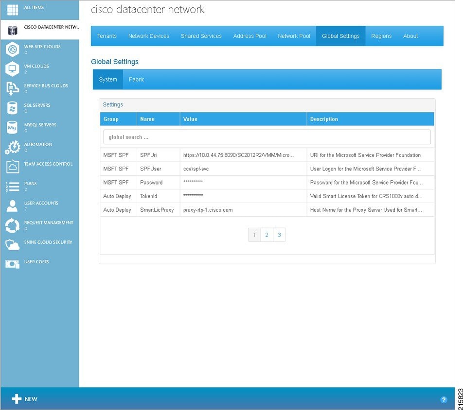
Step 2![]() Move the cursor over the first row of the settings table to highlight the row. Click the highlighted row.
Move the cursor over the first row of the settings table to highlight the row. Click the highlighted row.
You see a pop-up window, as shown in the following screen.
Figure 2-2 Global System Settings Screen—Parameter Pop-up Window
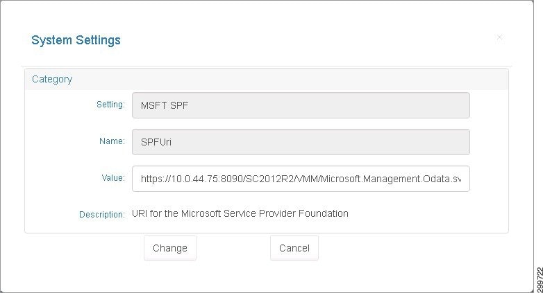
Step 3![]() You can specify or change the value for the parameter. When you are finished, click Change. Click Cancel to return to the previous screen without entering/changing any values.
You can specify or change the value for the parameter. When you are finished, click Change. Click Cancel to return to the previous screen without entering/changing any values.
Step 4![]() Highlight each row in turn and specify or change the value for each parameter in the pop-up windows. When you are finished with the parameters on the first screen, click 2 at the bottom of the screen to see the next set of values.
Highlight each row in turn and specify or change the value for each parameter in the pop-up windows. When you are finished with the parameters on the first screen, click 2 at the bottom of the screen to see the next set of values.
There are several screens where you can specify/change System Global Settings. Table 2-1 describes the various fields and their possible values.
|
|
|
|
|
https://{ spf-server-name }:8090/SC2012/{provider-service}/{subscription-id}/Microsoft.Management.Odata.svc/ |
|||
Valid Smart License Token for Cisco CRS1000V auto deployment |
|||
Host Name for the Proxy Server Used for Smart Licensing Validation |
|||
TCP Port for the Proxy Server Used for Smart Licensing Validation |
|||
Administrator User Logon set at BOOTSTRAP of the Cisco CSR 1000V |
|||
Administrator Password set at BOOTSTRAP of the Cisco CSR 1000V. You can change the password when initially defining global settings. Follow good security practices to set a secure password. However once you have onboarded devices, you cannot change the password since that will cause container creation to fail. |
|||
Prefix source used for auto-generated Route Descriptors. Options are PEBundle or PEautoSystemNumber. |
|
1.The values shown are examples. Use values appropriate for your cloud environment. |
Configuring Global Fabric Settings
Step 1![]() On the Tenants list screen, click the Global Settings tab, then click the Fabric tab.
On the Tenants list screen, click the Global Settings tab, then click the Fabric tab.
You see the Global Fabric Settings screen, as shown in the following screen.
Figure 2-3 Global Fabric Settings Screen

Step 2![]() Move the cursor over the first row of the settings table to highlight the row. Click the highlighted row.
Move the cursor over the first row of the settings table to highlight the row. Click the highlighted row.
Step 3![]() You can specify or change the value for the parameter. When you are finished, click Change. Click Cancel to return to the previous screen without entering/changing any values.
You can specify or change the value for the parameter. When you are finished, click Change. Click Cancel to return to the previous screen without entering/changing any values.
Step 4![]() Highlight each row in turn and specify or change the value for each parameter in the pop-up windows. When you are finished with the parameters on the first screen, click 2 at the bottom of the screen to see the next set of values.
Highlight each row in turn and specify or change the value for each parameter in the pop-up windows. When you are finished with the parameters on the first screen, click 2 at the bottom of the screen to see the next set of values.
There are three screens where you can specify or change Fabric Global Settings. Table 2-2 describes the various fields and their possible values.
|
|
|
|
|
|
Bundle-Ethernet or Port-channel interface on the PE connecting to the Cisco ACI Fabric. For the Cisco ASR 9000, the value is in the range <1-65535> For the Cisco ASR 1000, the value is the range <1-64>.
Note |
||||
Cisco APIC Virtual Machine Manager (VMM) Domain. The VMM domain is located in the Cisco APIC GUI under VM Networking −> Inventory −> Microsoft. |
||||
Name used for the Layer 2 Bridge Domain in the Cisco APIC if you are provisioning Zinc containers with a Single Cisco CSR 1000V or a Cisco CSR 1000V pair for each customer. In the Cisco APIC GUI, navigate to Fabric −> Access Policies −> Physical and External Domains −> External Bridge Domains and select the domain that is assigned to the VLAN pool corresponding to the Network pool defined in Cisco CNAP. |
||||
For a multi-CSR Zinc container, the physical domain name is used instead. In the Cisco APIC GUI, navigate to Fabric −> Access Policies −> Physical and External Domains −> Physical Domains and select the domain that is assigned to the VLAN pool corresponding to the Network pool defined in Cisco CNAP for asr9k connectivity. |
||||
Cisco ACI Leaf Node 1 ID which is part of the vPC to PE router. In the Cisco APIC GUI, navigate to Fabric −> Inventory −> Fabric Membership to view the node ID of all switches in the Cisco ACI fabric. |
||||
Cisco ACI Leaf Node 2 ID which is part of the vPC to PE router. In the Cisco APIC GUI, navigate to Fabric −> Inventory −> Fabric Membership to view the node ID of all switches in the Cisco ACI fabric. |
||||
Policy Group name for the vPC connecting the Cisco ACI leaf pair to PE1. In the Cisco APIC GUI, navigate to Fabric −> Access Policies −> Interface Policies −> Profiles and select the interface profile corresponding to the vPC. Use the Policy Group name associated with this interface profile. |
||||
Policy Group name for the vPC connecting the Cisco ACI leaf pair to PE2. |
||||
Bundle-Ethernet or Port-channel interface on PE2 connecting to the Cisco ACI Fabric.
Note |
||||
Cisco APIC Virtual Machine Manager (VMM) Controller defined under the VmmDom (VMM Domain) described above. The VMM controller name is located in the Cisco APIC GUI under VM Networking −> Inventory −> Microsoft −> < domain > −> Controllers. |
||||
Internet Network Name connecting to Internet for Internet provisioning. |
||||
Internal HSRP Group ID starting index for Internet provisioning. |
|
2.The values shown are examples. Use values appropriate for your cloud environment. |
Starting the Cisco.Network.Provisioner Windows Service
Note![]() You typically perform this step as part of the post-installation set up procedures for Cisco CNAP. For more information, see the section Post-installation Set Up Procedures in Installing Cisco Cloud Network Automation Provisioner for the Microsoft Cloud Platform, Release 2.1.
You typically perform this step as part of the post-installation set up procedures for Cisco CNAP. For more information, see the section Post-installation Set Up Procedures in Installing Cisco Cloud Network Automation Provisioner for the Microsoft Cloud Platform, Release 2.1.
The Cisco.Network.Provisioner Windows Service is installed as part of the Cisco CNAP installation process, however it is not started automatically since the Global System settings must first be set.
At this point, starting the Cisco.Network.Provisioner Windows Service loads all the global settings into the Cisco CNAP backend orchestrator and creates the Cloud record(s).
To start the Cisco.Network.Provisioner Windows Service:
Step 1![]() Start Windows Task Manager.
Start Windows Task Manager.
Note![]() You can also use the Windows Start menu to search for Windows services.
You can also use the Windows Start menu to search for Windows services.
Step 2![]() Click the Services tab.
Click the Services tab.
Step 3![]() In the list of services, locate Cisco.Network.Provisioner, right-click it, and in the pop-up window that appears, click Start.
In the list of services, locate Cisco.Network.Provisioner, right-click it, and in the pop-up window that appears, click Start.
Setting Up and Configuring Regions
You can think of a region as a geographic area or a particular facility containing managed devices and containers. For example, one region might be used to indicate managed devices in Data Center 1 (DC1), used as the primary site for a particular tenant’s hosted applications, and another region might be Data Center 2 (DC2), used as the secondary site in the event of an outage at DC1. Note that regions could be co-located in the same facility (e.g., in a particular room or cabinet row) or a region could indicate a set of remotely managed CPE devices (e.g., for a remote region).
On the Regions tab screen, you can:
Understanding the Concept of Regions
As implemented by Cisco CNAP, Regions in effect comprise availability zones. However, in contrast to Openstack (where for example each AZ has a unique Openstack instance), in this case, the Regions are all under the control of a single WAP and Cisco CNAP instance. Thus WAP logical constraints apply, limiting the total number of supported SCVMM instances in the system to five and the total number of VM clouds per SCVMM to four. Additionally, the Cisco ACI APIC to SCVMM agent, which provides for seamless integration of the Cisco Nexus 9000 DC switching fabrics with the VM Clouds within the overall system, constrains the relationship of ACI fabric to SCVMM instances to 1:N, where the maximum value for N is five (i.e., the maximum number of SCVMMs supported by WAP).
Figure 2-4 illustrates an example of a multi-Region, single WAP and Cisco CNAP administrative domain system. Note that the system shows the maximum number of possible SCVMM instances per WAP.
Figure 2-4 Multi-Region—Single WAP and Cisco CNAP System
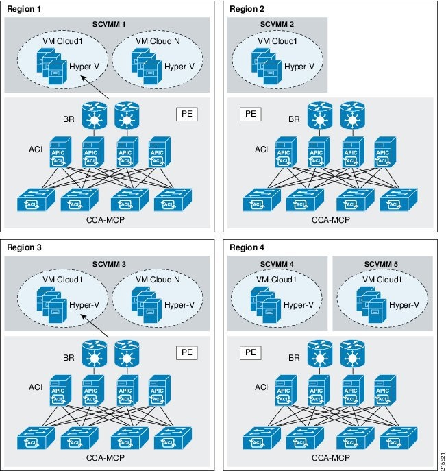
As previously discussed, while some of the regions above feature multiple SCVMM instances, they each have only one ACI fabric, preserving the 1:N relationship of ACI to SCVMM systems.
Note![]() In this release, Cisco CNAP only automates pushing of per-tenant routing information to the directly-attached Border Routers (BRs) in the system. Though technically possible, end-to-end routing between regions is not automated, as the assumption is that Provider-Edge (PE) to PE routed paths will be under the administrative control of a separate backbone transport operational team. Thus the BRs serve the role of an intra-DC or intra-Region administrative demarcation point.
In this release, Cisco CNAP only automates pushing of per-tenant routing information to the directly-attached Border Routers (BRs) in the system. Though technically possible, end-to-end routing between regions is not automated, as the assumption is that Provider-Edge (PE) to PE routed paths will be under the administrative control of a separate backbone transport operational team. Thus the BRs serve the role of an intra-DC or intra-Region administrative demarcation point.
Similarly, although the virtual machines or associated storage in a tenant container in one region may serve as backup resources for those in another container in another region, the tenant may only view network tiers and apply firewall policies for these workloads on a per-container basis because the container remains a logical routed boundary. The assumption is that in this case unique SCVMM instances will be utilized per Region.
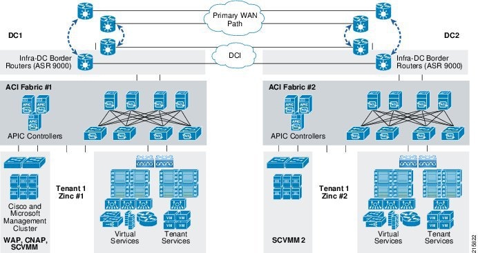
Figure 2-5 illustrates a two-region system, with one management POD in Region “DC1” and a second SCVMM system associated with Region “DC2”. Figure 2-5 also more fully depicts the administrative demarcation of the PE routers, serving as the Layer 3 gateway to the provider backbone transport networks, versus the BRs, serving as Layer 3 gateways to DC staff-administered Data Center Interconnect networks.
Figure 2-5 Dual-DC with Single WAP and Cisco CNAP Management Fabric
When you configure data center devices, network pools, and address pools, you must indicate the Region with which these network resources will be associated. For more information, see Chapter3, “Building the Pool of Available Cloud Resources”
Note![]() You must have at least one region defined in CNAP. If you only have one region, you must set up and group all network devices, IP pools, VLAN ranges, etc. into that one region.
You must have at least one region defined in CNAP. If you only have one region, you must set up and group all network devices, IP pools, VLAN ranges, etc. into that one region.
The resources within the scope of a particular region could include APIC clusters and nodes, MPLS and Internet gateway nodes (and related routing systems such as BGP or others), ASA5500 firewalls, and SCVMM controllers and their associated VM networks.
Adding a Region
Step 1![]() On the Regions Tab screen, place the cursor over the plus sign (+), which displays the New Region tooltip, and click it, as shown in the following screen.
On the Regions Tab screen, place the cursor over the plus sign (+), which displays the New Region tooltip, and click it, as shown in the following screen.
Figure 2-6 Regions Tab Screen—Add New Region Button
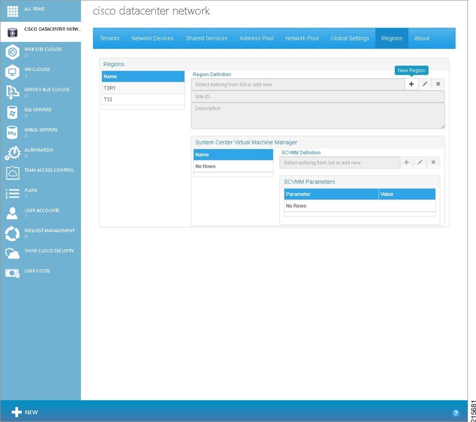
Figure 2-7 Regions Tab Screen—Add Region Popup
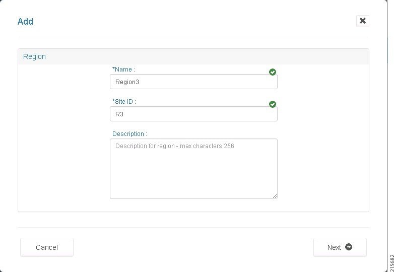
Step 2![]() Enter a Name, Site ID (must be at least two characters), and an optional Description.
Enter a Name, Site ID (must be at least two characters), and an optional Description.
A Side ID is a site identifier that is part of a container name. The Site ID appears in the container name in the format xxxxxxx-nn-xxxxx, where nn is the Site ID.
When you are finished, click the Next arrow. You see the following screen
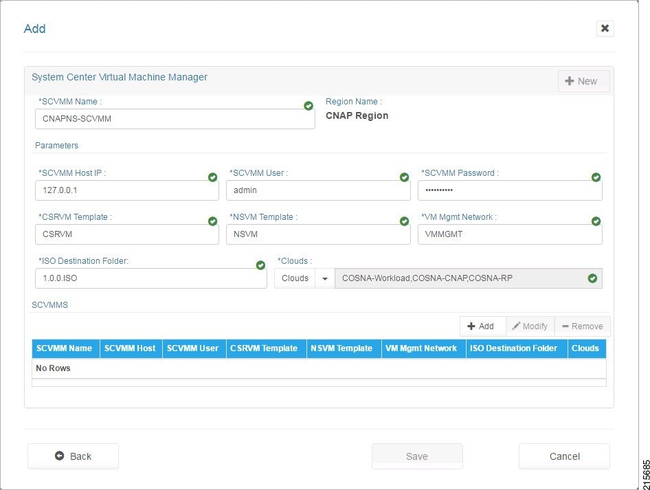
Figure 2-8 Regions Tab Screen—Associate SCVMM to Region Popup
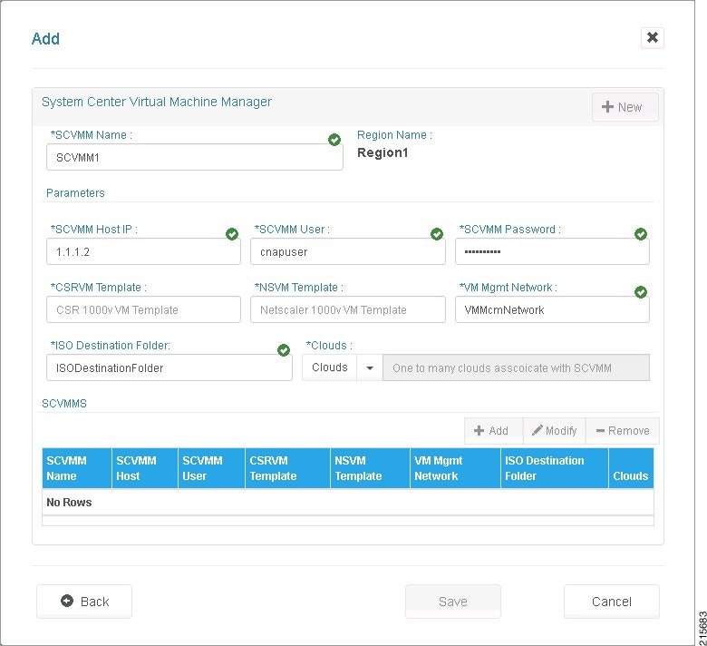
Step 3![]() Complete the following fields to associate an SCVMM to the Region you are adding:
Complete the following fields to associate an SCVMM to the Region you are adding:
- SCVMM Name—Name of the SCVMM.
- SCVMM Host IP—FQN/IP Address of System Center VMM Host.
- SCVMM User—User Logon for the Microsoft System Center VMM.
- SCVMM Password—Password for the Microsoft System Center VMM.
- CSRVM Template—Name of the Cisco CSR 1000V VM Template. For more information, see Creating the Cisco CSR 1000V Template Used by Cisco CNAP.
- NSVM Template—Name of the Citrix NetScaler VPX VM Template. Not supported in the current release.
- VM Mgmt Network—VMNetwork used for management of the Cisco CSR 1000Vs. This is not the Logical Switch.
- ISO Destination Folder—Folder at the System Center VMM Host to hold post-deployment ISOs.
Step 4![]() Use the Clouds pull-down menu to associate clouds with the SCVMM, as shown in the following screen.
Use the Clouds pull-down menu to associate clouds with the SCVMM, as shown in the following screen.
Figure 2-9 Regions Tab Screen—Cloud Pull-down Menu
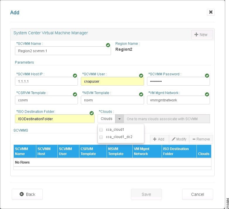
You can associate more than one Cloud, as shown in the following screen.
Figure 2-10 Regions Tab Screen—Two Clouds Selected
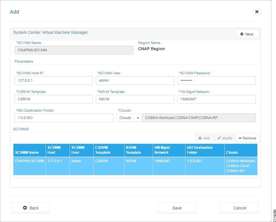
Step 5![]() When you are finished, click + Add.
When you are finished, click + Add.
The SCVMM is added to the SCVMMS table, as shown in the following screen.
Figure 2-11 Regions Tab Screen—SCVMM Added to List
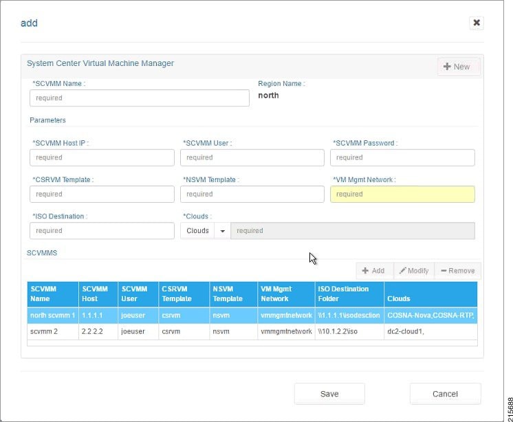
Step 6![]() You can associate additional SCVMMs. In the upper right, click + New, complete the fields, and when you click +Add, each is added to the SCVMMS table, as shown in the following screen.
You can associate additional SCVMMs. In the upper right, click + New, complete the fields, and when you click +Add, each is added to the SCVMMS table, as shown in the following screen.
Figure 2-12 Regions Tab Screen—Second SCVMM Added
You can also add additional SCVMMs to a Region from the main Regions Tab screen. Next to the SCVMM Definition field, click the + (plus sign), as shown in the following screen.
Figure 2-13 Regions Tab Screen—Add New SCVMM
On the screen shown in Figure 2-8, in the upper right, click + New, complete the fields, and when you click +Add, the SCVMM is added to the SCVMMS table.
Step 7![]() When you are finished associating SCVMMs, click Save.
When you are finished associating SCVMMs, click Save.
You see the following screen with the Region(s) you added displayed.
Figure 2-14 Regions Tab Screen—Region Added
Viewing Information about a Region
To view information about a region:
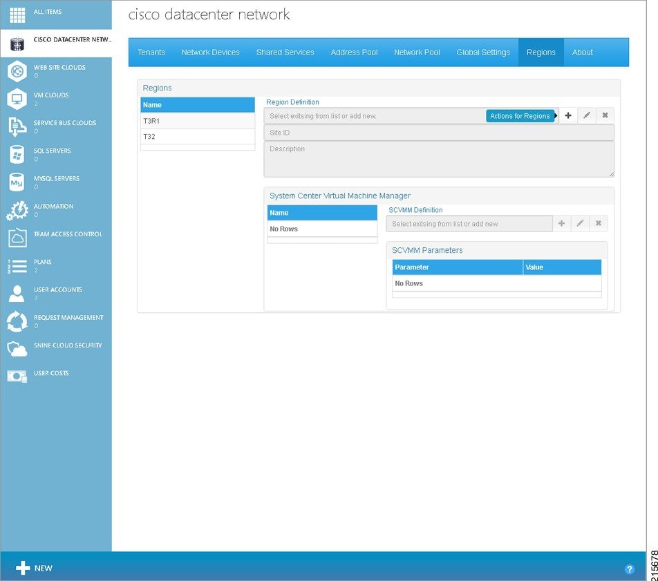
Step 1![]() On the main Admin Portal screen, click the Regions tab. You see the following screen.
On the main Admin Portal screen, click the Regions tab. You see the following screen.
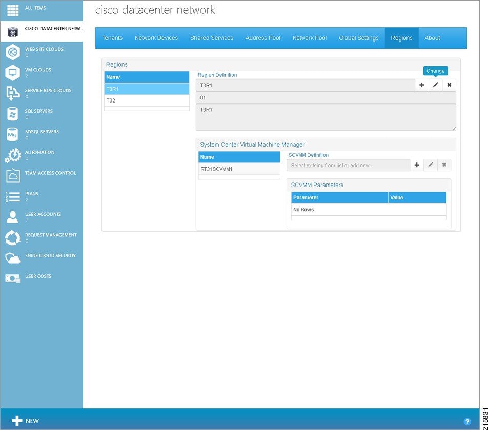
Figure 2-15 Regions Tab Screen
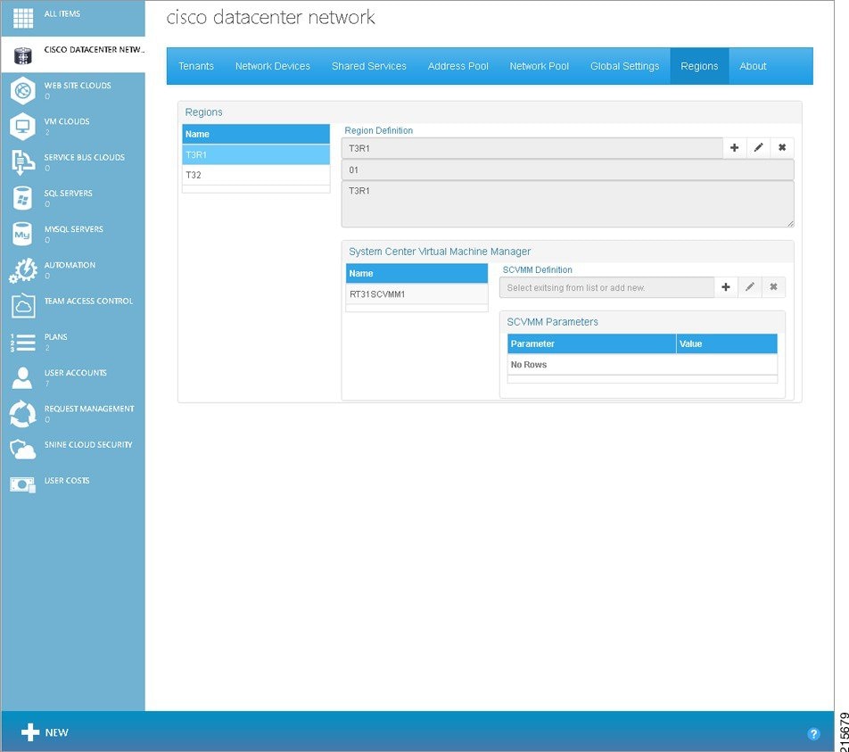
Step 2![]() On the left of the screen under Regions, click the name of a region. You see the following screen.
On the left of the screen under Regions, click the name of a region. You see the following screen.
Figure 2-16 Regions Tab Screen—Region Selected
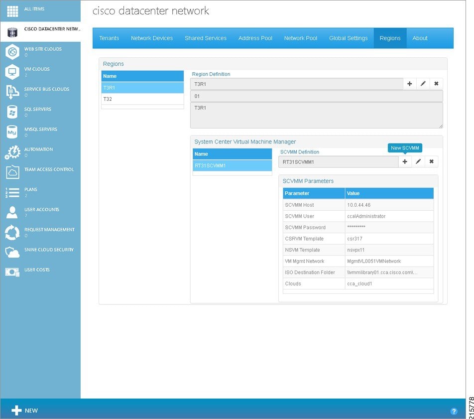
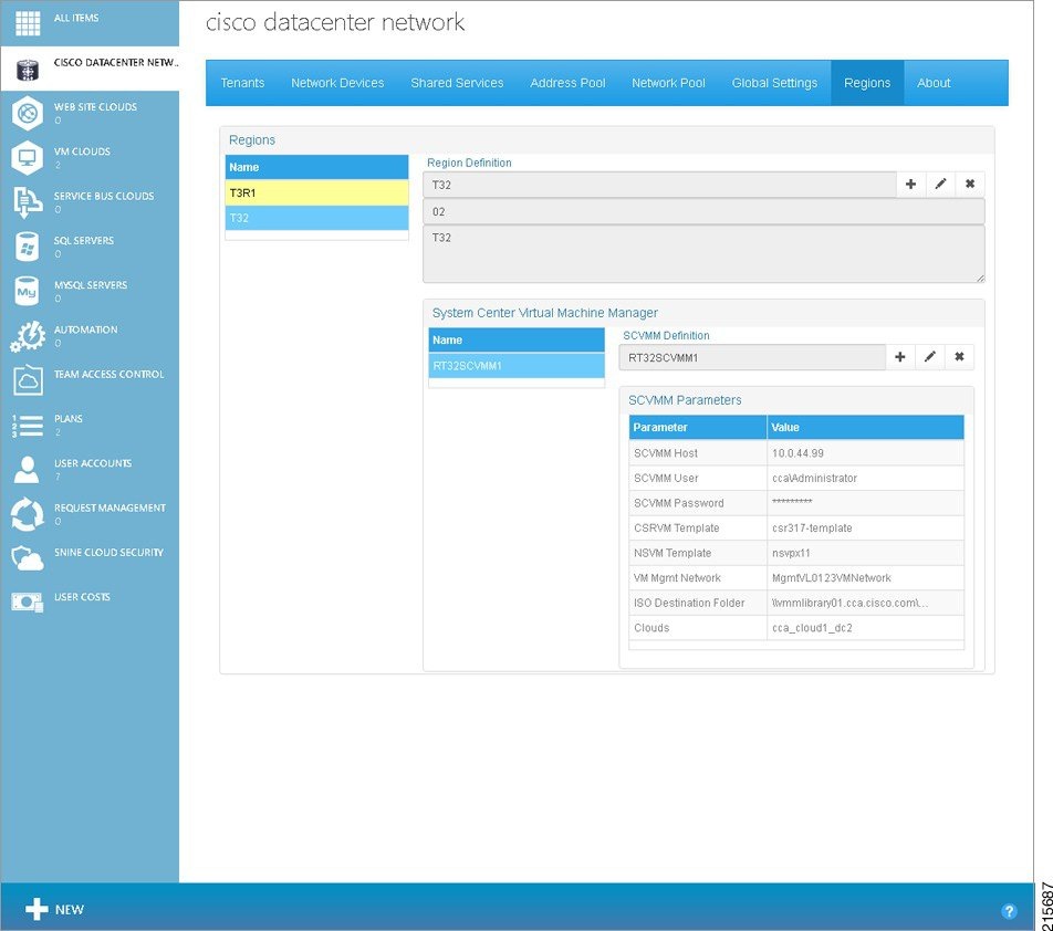
Step 3![]() Under System Center Virtual Machine Manager, click the name of a SCVMM. You see the following screen.
Under System Center Virtual Machine Manager, click the name of a SCVMM. You see the following screen.
Figure 2-17 Regions Tab Screen—SCVMM Selected
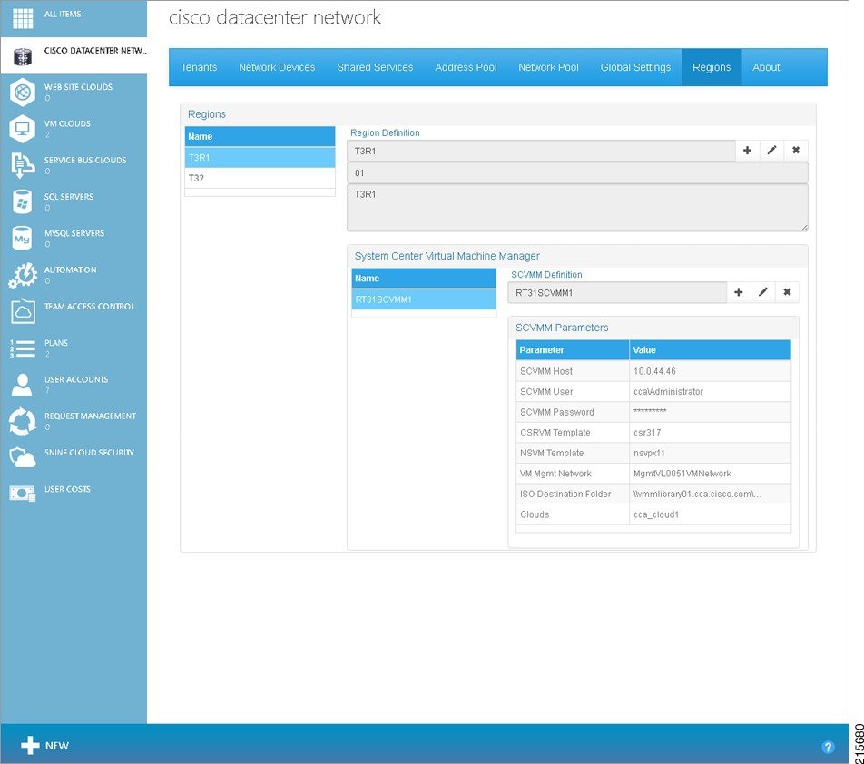
Under SCVMM Parameters, you see values for the following parameters for the selected SCVMM:
- SCVMM Host—FQN/IP Address of System Center VMM Host.
- SCVMM User—User Logon for the Microsoft System Center VMM.
- SCVMM Password—Password for the Microsoft System Center VMM.
- CSRVM Template—Name of the Cisco CSR 1000V VM Template. For more information, see Creating the Cisco CSR 1000V Template Used by Cisco CNAP.
- NSVM Template—Name of the Citrix NetScaler VPX VM Template. Not supported in the current release.
- VM Mgmt Network—VMNetwork used for management of the Cisco CSR 1000Vs. This is not the Logical Switch.
- ISO Destination Folder—Folder at the System Center VMM Host to hold post-deployment ISOs.
- Clouds—Clouds associated with the SCVMM.
Modifying a Region
Modifying the Description of a Region
To modify the description of a Region:
Step 1![]() On the Regions Tab screen, in the list of Regions, click the Region you want to modify, then hover the cursor over the pencil icon to display the Change option, as shown in the following screen.
On the Regions Tab screen, in the list of Regions, click the Region you want to modify, then hover the cursor over the pencil icon to display the Change option, as shown in the following screen.
Figure 2-18 Change Region Icon
Step 2![]() Click Change. You see the following screen.
Click Change. You see the following screen.
Figure 2-19 Region Change Description
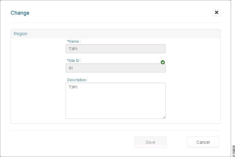
Step 3![]() Under Description, change the description, then click Save.
Under Description, change the description, then click Save.
Modifying SCVMM Parameters for a Region
Step 1![]() You can modify SCVMM parameters in two ways:
You can modify SCVMM parameters in two ways:
- On the Regions Tab screen, in the list of SCVMMs, click the SCVMM you want to modify, then under SCVMM Definition, click the pencil icon next to the name of the SCVMM.
- On the screen where you associate SCVMM(s) to a Region, click the SCVMM you want to modify.
The parameter values for the selected SCVMM are displayed, as shown in the following screen.
Figure 2-20 SCVMM Change screen

Step 2![]() Change the values for any of the parameters. When you are finished, click Save.
Change the values for any of the parameters. When you are finished, click Save.
The updated values are reflected in the entry in the SCVMMS table.
Removing a Region
You can remove a region subject to the following restrictions:
- Before you can remove a region, you must remove the SCVMM(s) associated with the region.
- Before you can remove an SCVMM, you must remove any plans and containers associated with the SCVMM.
If you attempt to remove a region without completing these steps, you will see an error message.
Step 1![]() On the Region Tab screen, in the list of Regions, click the Region you want to remove, then click the X (Remove) button next to the name of the Region. You see the following screen.
On the Region Tab screen, in the list of Regions, click the Region you want to remove, then click the X (Remove) button next to the name of the Region. You see the following screen.
Figure 2-21 Region Remove screen
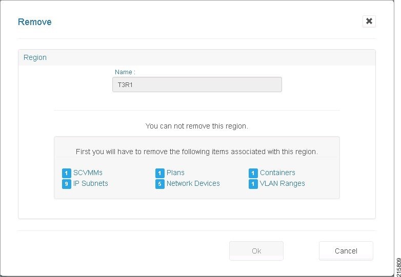
You have to delete the indicated resources, such as SCVMMs, IP Subnets, Plans, Network Devices, Containers, and VLAN Ranges.
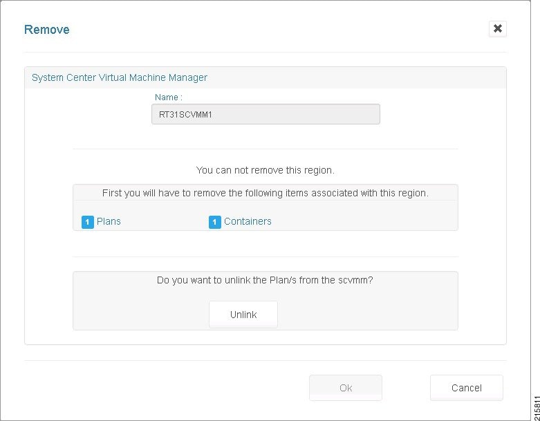
Step 2![]() If there are SCVMMs associated with the Region, you must remove the SCVMM(s). On the screen where you associate SCVMM(s) to a Region, click the SCVMM you want to remove, then click Remove. You see the following screen.
If there are SCVMMs associated with the Region, you must remove the SCVMM(s). On the screen where you associate SCVMM(s) to a Region, click the SCVMM you want to remove, then click Remove. You see the following screen.
Step 3![]() You have to remove any resources associated with the region before you can remove it. If there are additional SCVMMs associated with the region you are removing, remove those SCVMMs using the same procedure.
You have to remove any resources associated with the region before you can remove it. If there are additional SCVMMs associated with the region you are removing, remove those SCVMMs using the same procedure.
Step 4![]() When you have finished removing SCVMMs, on the Regions Tab screen, remove the region.
When you have finished removing SCVMMs, on the Regions Tab screen, remove the region.
Restarting the Cisco.Network.Provisioner Windows Service
At this point, restarting the Cisco.Network.Provisioner Windows Service loads the configuration changes into the Cisco CNAP backend orchestrator.
To restart the Cisco.Network.Provisioner Windows Service:
Step 1![]() Start Windows Task Manager.
Start Windows Task Manager.
Note![]() You can also use the Windows Start menu to search for Windows services.
You can also use the Windows Start menu to search for Windows services.
Step 2![]() Click the Services tab.
Click the Services tab.
Step 3![]() In the list of services, locate Cisco.Network.Provisioner, right-click it, and in the pop-up window that appears, click Start.
In the list of services, locate Cisco.Network.Provisioner, right-click it, and in the pop-up window that appears, click Start.
 Feedback