VMDC 2.3 Implementation Guide
Bias-Free Language
The documentation set for this product strives to use bias-free language. For the purposes of this documentation set, bias-free is defined as language that does not imply discrimination based on age, disability, gender, racial identity, ethnic identity, sexual orientation, socioeconomic status, and intersectionality. Exceptions may be present in the documentation due to language that is hardcoded in the user interfaces of the product software, language used based on RFP documentation, or language that is used by a referenced third-party product. Learn more about how Cisco is using Inclusive Language.
- Updated:
- April 8, 2013
Chapter: Compute and Storage Implementation
Compute and Storage Implementation
The Virtualized Multiservice Data Center (VMDC) 2.3 solution uses modular blocks for Compute and Storage, generically referred to as Integrated Compute and Storage (ICS) stacks. A number of these stacks can be attached to a pod, providing compute and storage scale. The limiting factor in terms of the number of Virtual Machines (VMs) supported in an ICS, pod, and Data Center (DC) is usually multi-dimensional, and in this design, the key parameter for the per-pod limit is the number of MAC addresses on the Nexus 7000 aggregation. With the low cost design based on F2 modules on the Nexus 7004, this is limited to 5000 to 6000 VMs assuming dual-Network Interface Card (NIC) VMs. The other limitation is the number of ports on the Nexus 7004 connecting to each ICS stack, and affecting the bandwidth for north-south as well as east-west routed traffic. In this design, three ICS stacks can be connected to the Nexus 7004, with 4x 10G links per aggregation switch, for a total of 80G to the ICS switch layer. Refer to the Cisco VMDC 2.3 Design Guide for more discussion of the scaling factors.
For validation purposes, a smaller footprint ICS was built as listed in Table 2-1. The ICS design is FlexPod-like and uses the NetApp 6040 as the storage for both SAN and NAS. The details of the test build out are covered in the subsections below.
|
|
|
|
|
|
Gold |
10 |
Private (PVT) Zone - 3 Demilitarized Zone (DMZ) - 1 |
3 per VLAN (12 VMs) |
120 |
Silver |
20 |
3 |
3 per VLAN (9 VMs) |
180 |
Bronze |
10 |
1 |
6 |
60 |
Copper |
10 |
1 |
6 |
60 |
Total |
50 |
- |
- |
420 |
|
|
The following sections show the considerations and configurations while implementing compute and storage for VMDC 2.3, including the virtual Switching layer based on the Nexus 1000V:
•![]() Cisco Unified Computing System Implementation
Cisco Unified Computing System Implementation
•![]() Storage Implementation Overview
Storage Implementation Overview
•![]() Hypervisor vSphere ESXi Implementation
Hypervisor vSphere ESXi Implementation
•![]() 2.5 Compute and Storage Best Practices and Caveats
2.5 Compute and Storage Best Practices and Caveats
Cisco Unified Computing System Implementation
This section presents the following topics:
UCS Configuration
Figure 2-1 shows an overview of the Cisco Unified Computing System (UCS) setup.
Figure 2-1 UCS Physical Layout
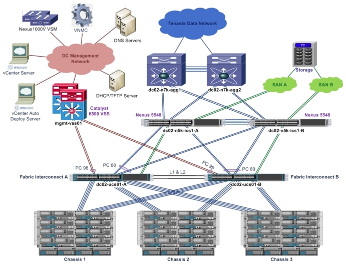
Table 2-2 details the UCS hardware used for the compute infrastructure.
1. ![]() For the test implementation, only a small scale, three-chassis compute infrastructure is set up. More chassis and blade servers can be added to support larger scale deployment.
For the test implementation, only a small scale, three-chassis compute infrastructure is set up. More chassis and blade servers can be added to support larger scale deployment.
2. ![]() The test implementation includes both UCS B200-M2 and B200-M3 blades servers, as both types are supported. The UCS B200-M3 blade server has more CPU resources.
The test implementation includes both UCS B200-M2 and B200-M3 blades servers, as both types are supported. The UCS B200-M3 blade server has more CPU resources.
3. ![]() The test implementation includes three types of Cisco virtualized adapters. All three types of virtualized adapters used the same driver on vSphere ESXi and are supported.
The test implementation includes three types of Cisco virtualized adapters. All three types of virtualized adapters used the same driver on vSphere ESXi and are supported.
The following list highlights the Cisco Unified Computing System Manager (UCSM) configuration:
•![]() The UCS FIs are configured into a cluster to provide active/standby management plane redundancy for the UCSM. The data plane for the UCS operates in active/active mode.
The UCS FIs are configured into a cluster to provide active/standby management plane redundancy for the UCSM. The data plane for the UCS operates in active/active mode.
•![]() The UCS FIs are configured in End-host (EH) mode.
The UCS FIs are configured in End-host (EH) mode.
•![]() Three UCS 5108 chassis are connected to a pair of UCS 6248 FIs.
Three UCS 5108 chassis are connected to a pair of UCS 6248 FIs.
•![]() Each chassis has four server links to each FI.
Each chassis has four server links to each FI.
•![]() The uplinks on the FIs are bundled into port-channels to upstream switches with disjoint Layer 2 (L2) networks. Refer to UCS Uplinks Configuration for more details.
The uplinks on the FIs are bundled into port-channels to upstream switches with disjoint Layer 2 (L2) networks. Refer to UCS Uplinks Configuration for more details.
•![]() The FIs connect to two Nexus 5000 switches with Fibre Channel (FC) links for access to SAN storage. Refer to Storage Implementation Overview for more details.
The FIs connect to two Nexus 5000 switches with Fibre Channel (FC) links for access to SAN storage. Refer to Storage Implementation Overview for more details.
•![]() The UCSM configuration make use of updating templates to ensure consistent configuration and updates across all blade servers.
The UCSM configuration make use of updating templates to ensure consistent configuration and updates across all blade servers.
•![]() The BIOS policy for each blade server is optimized for ESXi hypervisor application. Refer to UCS and VMware documentation for more details.
The BIOS policy for each blade server is optimized for ESXi hypervisor application. Refer to UCS and VMware documentation for more details.
•![]() The blade servers are configured to boot via vSphere Auto Deploy, and boot disk (SAN or local) is not required on each blade server. Refer to Hypervisor vSphere ESXi Implementation for more details.
The blade servers are configured to boot via vSphere Auto Deploy, and boot disk (SAN or local) is not required on each blade server. Refer to Hypervisor vSphere ESXi Implementation for more details.
•![]() Networking for each blade server (ESXi hypervisor) is managed by the Nexus 1000V. Refer to Nexus 1000V Series Switches for more details.
Networking for each blade server (ESXi hypervisor) is managed by the Nexus 1000V. Refer to Nexus 1000V Series Switches for more details.
•![]() Each blade server is configured with four Virtual Network Interface Cards (vNICs) for access to the disjoint upstream L2 networks for redundancy. On the UCSM, fabric failover for each vNIC is not required/enabled.
Each blade server is configured with four Virtual Network Interface Cards (vNICs) for access to the disjoint upstream L2 networks for redundancy. On the UCSM, fabric failover for each vNIC is not required/enabled.
•![]() Each blade server is configured with two Virtual Host Bus Adapters (vHBAs) for access to SAN storage via SAN-A and SAN-B for storage multipathing. Refer to Storage Implementation Overview for more details.
Each blade server is configured with two Virtual Host Bus Adapters (vHBAs) for access to SAN storage via SAN-A and SAN-B for storage multipathing. Refer to Storage Implementation Overview for more details.
1. ![]() Disjoint L2 upstream network configuration on the UCSM requires EH mode on the UCS FIs.
Disjoint L2 upstream network configuration on the UCSM requires EH mode on the UCS FIs.
2. ![]() Some configuration changes will either cause server reboot or service disruption. Multiple templates of the same type should be used to prevent any single change to cause service disruption to all blade servers.
Some configuration changes will either cause server reboot or service disruption. Multiple templates of the same type should be used to prevent any single change to cause service disruption to all blade servers.
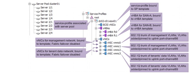
Figure 2-2 shows the service-profile configuration for one of the blade servers on the UCSM. Updating service-profile templates, updating vNIC templates, and updating vHBA templates are used to ensure that the configuration across multiple blade servers are consistent and up to date. Server pools are configured, and each service-profile is associated with its respective server pool. Each server pool has blade servers from two or more chassis for redundancy purposes.
Figure 2-2 Service-Profile Configuration
UCS Uplinks Configuration
The UCS FIs connect to two upstream networks:
•![]() DC management network, for management/administration access to network devices and compute hypervisors
DC management network, for management/administration access to network devices and compute hypervisors
•![]() Network for tenants' data traffic
Network for tenants' data traffic
The two networks are not connected to each other. Access to both networks by all blades servers is necessary for proper operations of VMDC architecture. The upstream disjoint L2 networks' capability is configured to allow access to both networks.
Take note of the following considerations when configuring the disjoint L2 network on the UCSM:
•![]() The UCSM must be configured in EH mode.
The UCSM must be configured in EH mode.
•![]() In a High Availability (HA) UCSM cluster, symmetrical configuration on both fabric A and fabric B is recommended, and both FIs should be configured with the same set of VLANs.
In a High Availability (HA) UCSM cluster, symmetrical configuration on both fabric A and fabric B is recommended, and both FIs should be configured with the same set of VLANs.
•![]() UCSM verifies the VLANs' configuration, and the VLANs used for the disjoint L2 networks must be configured and assigned to an uplink Ethernet port or uplink Ethernet port channel.
UCSM verifies the VLANs' configuration, and the VLANs used for the disjoint L2 networks must be configured and assigned to an uplink Ethernet port or uplink Ethernet port channel.
•![]() UCSM does not support overlapping VLANs in disjoint L2 networks. Ensure that each VLAN only connects to one upstream disjoint L2 network.
UCSM does not support overlapping VLANs in disjoint L2 networks. Ensure that each VLAN only connects to one upstream disjoint L2 network.
•![]() A vNIC (VMNIC in the vSphere ESXi hypervisor or physical NIC in the bare metal server) can only communicate with one disjoint L2 network. If a server needs to communicate with multiple disjoint L2 networks, configure a vNIC for each of those networks.
A vNIC (VMNIC in the vSphere ESXi hypervisor or physical NIC in the bare metal server) can only communicate with one disjoint L2 network. If a server needs to communicate with multiple disjoint L2 networks, configure a vNIC for each of those networks.
•![]() Do not configure any vNICs with a default VLAN (VLAN ID 1).
Do not configure any vNICs with a default VLAN (VLAN ID 1).
By default, all VLANs are trunked to all available uplinks to maintain backward compatibility, however, this default behavior would cause a data traffic black hole when connecting the FIs to disjoint upstream L2 networks. VLANs must be explicitly assigned to the appropriate uplink(s) to ensure proper network operations. On the UCSM, VLANs are assigned to specific uplinks using the
LAN Uplinks Manager. Refer to UCSM documentation for more details about LAN Uplinks Manager usage.
Figure 2-3 UCS Disjoint Upstream L2 Network Layout
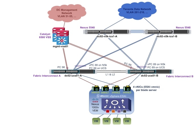
Figure 2-3 shows the disjoint L2 networks setup for this implementation. Each FI has two port-channel uplinks to two different upstream L2 networks. Each upstream L2 network has a completely non-overlapped set of VLANs. Table 2-3 shows the VLANs to uplink port-channel mapping.
On the Nexus 5548 upstream switches to the tenants' data network, a vPC is configured to provide redundancy for the UCS compute stack. The configuration of one of the Nexus 5548 devices is shown below; the other Nexus 5548 has similar configuration.
interface port-channel88
description vPC to dc02-ucs01-a
switchport mode trunk
  switchport trunk allowed vlan
201-210,301-310,401-410,501-520,601-620,701-720,801-820,1601-1610,1801-1860,
1990,2001-2010
spanning-tree port type edge trunk
vpc 88
interface port-channel89
description vPC to dc02-ucs01-b
switchport mode trunk
  switchport trunk allowed vlan
201-210,301-310,401-410,501-520,601-620,701-720,801-820,1601-1610,1801-1860,
1990,2001-2010
spanning-tree port type edge trunk
vpc 89
interface Ethernet2/1
description to UCS FI-A
switchport mode trunk
  switchport trunk allowed vlan
201-210,301-310,401-410,501-520,601-620,701-720,801-820,1601-1610,1801-1860,
1990,2001-2010
channel-group 88 mode active
interface Ethernet2/2
description to UCS FI-A
switchport mode trunk
  switchport trunk allowed vlan
201-210,301-310,401-410,501-520,601-620,701-720,801-820,1601-1610,1801-1860,
1990,2001-2010
channel-group 88 mode active
interface Ethernet2/3
description to UCS FI-B
shutdown
switchport mode trunk
  switchport trunk allowed vlan
201-210,301-310,401-410,501-520,601-620,701-720,801-820,1601-1610,1801-1860,
1990,2001-2010
channel-group 89 mode active
interface Ethernet2/4
description to UCS FI-B
switchport mode trunk
  switchport trunk allowed vlan
201-210,301-310,401-410,501-520,601-620,701-720,801-820,1601-1610,1801-1860,
1990,2001-2010
channel-group 89 mode active
The upstream to the management network is the Catalyst 6500 Virtual Switch System (VSS). A vPC is not required/supported on the VSS, as the VSS uses Multi-Chassis EtherChannel (MEC). The member links for each port-channel consist of switchports from two different chassis. The configuration of the Catalyst 6500 VSS is shown below.
interface Port-channel98
description dc02-ucs01-a
switchport
switchport trunk encapsulation dot1q
switchport trunk allowed vlan 51-55,119-121
switchport mode trunk
interface Port-channel99
description dc02-ucs01-b
switchport
switchport trunk encapsulation dot1q
switchport trunk allowed vlan 51-55,119-121
switchport mode trunk
end
interface TenGigabitEthernet1/4/7
switchport
switchport trunk encapsulation dot1q
switchport trunk allowed vlan 51-55,119-121
switchport mode trunk
channel-group 98 mode active
interface TenGigabitEthernet1/4/8
switchport
switchport trunk encapsulation dot1q
switchport trunk allowed vlan 51-55,119-121
switchport mode trunk
channel-group 99 mode active
interface TenGigabitEthernet2/4/7
switchport
switchport trunk encapsulation dot1q
switchport trunk allowed vlan 51-55,119-121
switchport mode trunk
channel-group 98 mode active
interface TenGigabitEthernet2/4/8
switchport
switchport trunk encapsulation dot1q
switchport trunk allowed vlan 51-55,119-121
switchport mode trunk
channel-group 99 mode active

Note ![]() UCS FI uses Link Aggregation Control Protocol (LACP) as the port-channel aggregation protocol. The opposing upstream switches must be configured with LACP active mode.
UCS FI uses Link Aggregation Control Protocol (LACP) as the port-channel aggregation protocol. The opposing upstream switches must be configured with LACP active mode.
In this implementation, each blade server needs to communicate with both the management network and the tenants' data network. Since each vNIC (VMNIC in the ESXi hypervisor) can only communicate with one disjoint L2 network, at least two vNICs are required; for redundancy, four vNICs (two for management network, two for tenants' data network) are deployed per blade server, as shown in the figure and table above. The need for four vNICs on each half-width B-Series blade server mandates use of the Cisco Virtual Interface Card. The following adapters are acceptable:
•![]() Cisco UCS Virtual Interface Card 1280
Cisco UCS Virtual Interface Card 1280
•![]() Cisco UCS Virtual Interface Card 1240
Cisco UCS Virtual Interface Card 1240
•![]() Cisco UCS M81KR Virtual Interface Card
Cisco UCS M81KR Virtual Interface Card
Figure 2-4 shows the disjoint upstream L2 networks configuration in the UCSM VLAN Manager. On UCSM, global VLANs are configured for HA, and each VLAN is added/pinned to the respective port-channel uplinks on fabric A and fabric B in accordance to which upstream L2 network the VLAN belongs to. The VLANs for both upstream L2 networks do not overlap.
Figure 2-4 Adding/Pinning VLANs to Upstream Port-channels
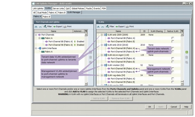
Note ![]() 1.UCSM implicitly assigns default VLAN 1 to all uplink ports and port-channels. Do not configure any vNICs with default VLAN 1. It is advisable not to use VLAN 1 for carrying any user data traffic.
1.UCSM implicitly assigns default VLAN 1 to all uplink ports and port-channels. Do not configure any vNICs with default VLAN 1. It is advisable not to use VLAN 1 for carrying any user data traffic.
2. UCSM reserved some VLANs for internal system use, and these reserved VLANs should not be used to carry any user management and data traffic.
Storage Implementation Overview
Storage is part of the ICS stack. In VMDC 2.3 implementation, the NetApp Filer FAS6040 is used to provide the storage needs of the solution. The FAS6040 is based on a unified storage architecture and provides Storage Area Network (SAN) and Network-Attached Storage (NAS) capabilities on a single platform. In this solution, a common infrastructure is used to provide both SAN and NAS capabilities. The Nexus 5548 ICS switch provides LAN capabilities for NAS connectivity, and also is the FC switch that connects server blades and storage to provide SAN capability.
For details on storage best practices, refer to the NetApp FlexPod Solutions Guide, which provides an overview of FlexPod.
This section presents the following topics:
•![]() NetApp FAS6040 Configuration Overview
NetApp FAS6040 Configuration Overview
SAN Implementation Overview
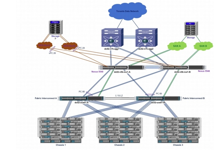
Figure 2-5 shows an overview of the SAN infrastructure. This section explains the Fibre Channel over Ethernet (FCoE) connection from servers to the FI and Fibre Channel (FC) connectivity to carry SAN traffic from the FI to the Nexus 5000 (storage switch) to NetApp Filers FAS6040.
Figure 2-5 Storage Infrastructure

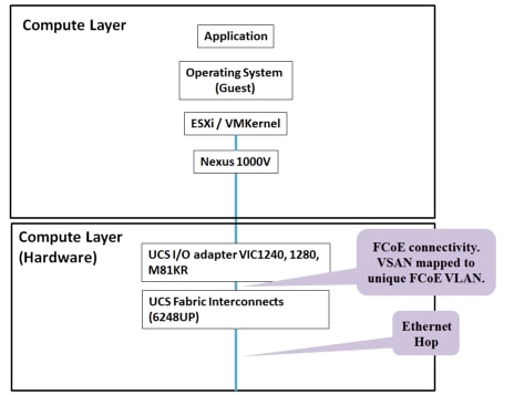
The following is an end-to-end flow diagram from application (user VM) to storage using SAN infrastructure. The compute, network, and storage portions of the flow are shown separately.
Compute
Figure 2-6 shows how the different components of the Compute layer are stacked up and the traffic that flows between them.
Figure 2-6 Compute Flow

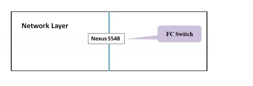
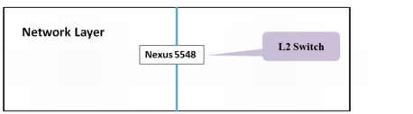
Network
Figure 2-7 shows the L2 switch, which is a Nexus 5500 series switch. Both the Server (Host) and Storage (NetApp Filer FAS6040) are connected to this switch, which is a part of the ICS stack.
Figure 2-7 Network Flow
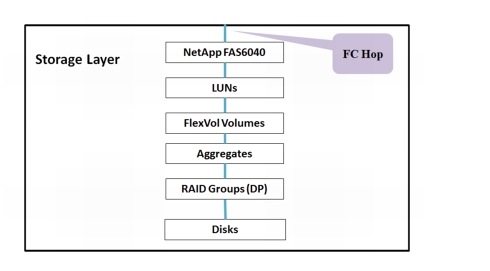
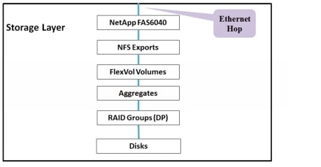
Storage
The NetApp FAS6040 provides the SAN storage, which is shown in Figure 2-8.
Figure 2-8 Storage Flow
This section presents the following topics:
•![]() FCoE in UCS Fabric Interconnect
FCoE in UCS Fabric Interconnect
•![]() SAN from Nexus 5500 to Storage
SAN from Nexus 5500 to Storage
FCoE in UCS Fabric Interconnect
The salient features of FC configuration in the DC are as follows:
•![]() Each blade server has two vHBAs that provide server to storage SAN connectivity. Virtual SANs (VSANs ) are used to provide scalability, availability, and security, and allows multiple VSANs to share the common SAN infrastructure.
Each blade server has two vHBAs that provide server to storage SAN connectivity. Virtual SANs (VSANs ) are used to provide scalability, availability, and security, and allows multiple VSANs to share the common SAN infrastructure.
•![]() Multiple vHBAs per blade server provide HBA redundancy at the server.
Multiple vHBAs per blade server provide HBA redundancy at the server.
•![]() Storage traffic from server blades to FIs is FCoE. Each VSAN is mapped to a unique VLAN that carries storage traffic from server to FI.
Storage traffic from server blades to FIs is FCoE. Each VSAN is mapped to a unique VLAN that carries storage traffic from server to FI.
•![]() FC traffic is mapped to a no-packet drop class using the system Quality of Service (Qos) policy. This assures that FC traffic will not be dropped during congestion.
FC traffic is mapped to a no-packet drop class using the system Quality of Service (Qos) policy. This assures that FC traffic will not be dropped during congestion.
•![]() Storage traffic from FIs to the Nexus 5548 ICS switch is sent as FC traffic using FC port-channels. Each port-channel has two links, and thus, provides link-level redundancy.
Storage traffic from FIs to the Nexus 5548 ICS switch is sent as FC traffic using FC port-channels. Each port-channel has two links, and thus, provides link-level redundancy.
•![]() Each FI is mapped to one VSAN. In this case, FI-A carries all VSAN61 traffic and FI-B carries all VSAN62 traffic.
Each FI is mapped to one VSAN. In this case, FI-A carries all VSAN61 traffic and FI-B carries all VSAN62 traffic.
•![]() The Nexus 5548 ICS switch is configured in N-port Identifier Virtualization (NPIV) mode. SAN storage traffic from FI-A is sent to the Nexus 5548 ICS switch-A; likewise, all of the SAN traffic from FI-B is sent to the Nexus 5548 ICS switch-B.
The Nexus 5548 ICS switch is configured in N-port Identifier Virtualization (NPIV) mode. SAN storage traffic from FI-A is sent to the Nexus 5548 ICS switch-A; likewise, all of the SAN traffic from FI-B is sent to the Nexus 5548 ICS switch-B.
•![]() The port-channel-trunk feature is enabled on the Nexus 5000 to enable port-channel configuration on FC interfaces connected to FIs.
The port-channel-trunk feature is enabled on the Nexus 5000 to enable port-channel configuration on FC interfaces connected to FIs.
Figure 2-9 configuration shows the list of VSANs in the SAN infrastructure: VSAN61, VSAN62, and the mapping of each of those VSANs to a unique FCoE VLAN ID (61,62). This mapping is required because both SAN and LAN traffic is carried using the same FCoE links between server and FIs. VSAN61 is transported on Fabric-A, and VSAN62 is transported on Fabric-B. Even though they share the common infrastructure, the traffic that flows on them is strictly isolated.
Figure 2-9 VSANs in the SAN Infrastructure
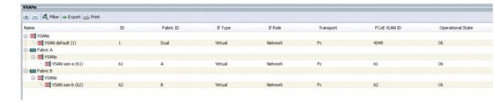
Figure 2-10 configuration shows the vHBA configuration on each server blade. vHBAs are configured using service profiles generated from service-profile templates. There are two vHBA adapters configured per server blade. As shown, vHBA0 traffic is sent on san-a, and vHBA1 traffic is sent on san-b. Each vHBA is placed on a unique, isolated SAN network.
Figure 2-10 vHBA Configuration on Each Server Blade
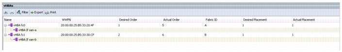
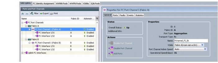
Figure 2-11 configuration shows the port-channel configuration of the FC between FI and the Nexus 5548 ICS switch for SAN traffic. Port-channel(1) is shown expanded in the right column. Portchannel(1) carries FC SAN traffic that flows on VSAN61 from FI-A to the Nexus 5548 ICS switch-A. Similarly, port-channel(2) carries VSAN62 traffic from FI-B to the Nexus 5548 ICS switch-B.
Figure 2-11 Port-channel Configuration of FC Between FI and Nexus 5548 ICS switch for SAN Traffic
SAN from Nexus 5500 to Storage
The following are the salient points of the SAN configuration:
•![]() Nexus 5000-A carries SAN-A(VSAN61) traffic from FIs to NetApp filer-A and filer-B. Similarly, Nexus 5000-B carries SAN-B(VSAN62) traffic.
Nexus 5000-A carries SAN-A(VSAN61) traffic from FIs to NetApp filer-A and filer-B. Similarly, Nexus 5000-B carries SAN-B(VSAN62) traffic.
•![]() FC links between the Nexus 5548 ICS switch and FIs are configured as the SAN port-channel.
FC links between the Nexus 5548 ICS switch and FIs are configured as the SAN port-channel.
•![]() Each Nexus is connected to both filer-A and filer-B for filer-level redundancy.
Each Nexus is connected to both filer-A and filer-B for filer-level redundancy.
•![]() The Nexus is configured in NPIV mode. FC ports connected to FIs or the NetApp Filer are configured as F ports. The Nexus 5548 ICS switch is configured to be the FC switch. The following configuration needs to be enabled on the FC switch, the Nexus 5548:
The Nexus is configured in NPIV mode. FC ports connected to FIs or the NetApp Filer are configured as F ports. The Nexus 5548 ICS switch is configured to be the FC switch. The following configuration needs to be enabled on the FC switch, the Nexus 5548:
feature npiv
feature fport-channel-trunk
•![]() Soft zoning (using World Wide Port Name (WWPN) names) is configured on the Nexus to allow servers with specific identity (WWPN) to communicate only with NetApp filers. Each filer connection has its own WWPN name. The configuration below shows the zoning configuration for one server blade per VSAN (in this case, SAN-B). As mentioned before, vHBA1 of any server blade is placed in the SAN-B infrastructure and vHBA0 is placed in SAN-A.
Soft zoning (using World Wide Port Name (WWPN) names) is configured on the Nexus to allow servers with specific identity (WWPN) to communicate only with NetApp filers. Each filer connection has its own WWPN name. The configuration below shows the zoning configuration for one server blade per VSAN (in this case, SAN-B). As mentioned before, vHBA1 of any server blade is placed in the SAN-B infrastructure and vHBA0 is placed in SAN-A.
The zoning configuration is shown below.
zone name dc02-c03-esxi08-hba1 vsan 62
pwwn 20:00:00:25:b5:33:30:9e \[dc02-c03-esxi08-hba1\] pwwn 50:0a:09:87:97:a9:91:d1
\[netapp-filera\] pwwn 50:0a:09:87:87:a9:91:d1 \[netapp-filerb\]
•![]() As you can infer from the above configuration, "single initiator zoning" has been implemented. Each zone contains only one host server vHBA and can contain multiple storage array targets in the same zone.
As you can infer from the above configuration, "single initiator zoning" has been implemented. Each zone contains only one host server vHBA and can contain multiple storage array targets in the same zone.
•![]() The FC interface on the Nexus 5548 ICS switch is used to connect to the NetApp FAS6040 for FC connectivity. Below is the interface configuration.
The FC interface on the Nexus 5548 ICS switch is used to connect to the NetApp FAS6040 for FC connectivity. Below is the interface configuration.
interface fc2/16
switchport mode F
switchport description to Netapp FAS6040-B no shutdown
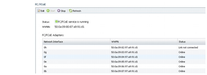
•![]() The WWPN of vHBAs is obtained from the UCSM (shown in the previous section). The WWPN of NetApp filers is fetched using the NetApp OnCommand System Manager GUI. Figure 2-12 is a screenshot that details the WWPN for each of the ports connected on Filer-a. An Online status implies that the FC link is up, whereas, an Offline status implies that the FC link is down.
The WWPN of vHBAs is obtained from the UCSM (shown in the previous section). The WWPN of NetApp filers is fetched using the NetApp OnCommand System Manager GUI. Figure 2-12 is a screenshot that details the WWPN for each of the ports connected on Filer-a. An Online status implies that the FC link is up, whereas, an Offline status implies that the FC link is down.
Figure 2-12 VWPN for Ports Connected on Filer-a
NetApp FAS6040
Figure 2-13 shows the end-to-end logical components within the NetApp FAS6040.
Figure 2-13 End-to-end Logical Components within the NetApp FAS6040
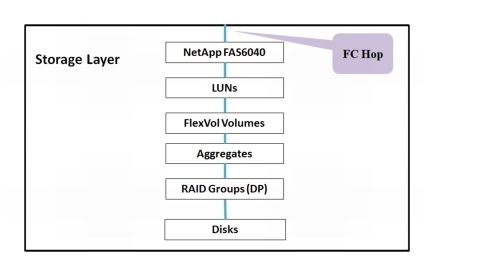
Starting from the bottom up, raw disks are formatted with a RAID group (in this case, RAID6) and grouped to form an Aggregate. From the Aggregate, volumes are carved out. From the volumes, LUNs are created. LUNs appear as logical disks to server hosts during a LUN scan.
The following are the salient features of the SAN configuration on the NetApp FAS6040:
•![]() Initiator groups are used to grant the server hosts access to LUNs.
Initiator groups are used to grant the server hosts access to LUNs.
•![]() To avoid problems with Virtual Machine File System (VMFS) resignaturing, it is recommended that within a SAN environment, all ESXi hosts refer to the same LUN using the same LUN ID.
To avoid problems with Virtual Machine File System (VMFS) resignaturing, it is recommended that within a SAN environment, all ESXi hosts refer to the same LUN using the same LUN ID.
•![]() In this implementation, a single initiator group is used for all of the VMware ESXi hosts in the SAN environment and then mapped LUNs to LUN IDs using that single initiator group, however, depending on the deployment and management needs, multiple initiator groups can also be used.
In this implementation, a single initiator group is used for all of the VMware ESXi hosts in the SAN environment and then mapped LUNs to LUN IDs using that single initiator group, however, depending on the deployment and management needs, multiple initiator groups can also be used.
The following steps show an overview of the SAN storage configuration:
1. ![]() Configure Aggregates on the NetApp filer from physical disks and configure RAID-DP.
Configure Aggregates on the NetApp filer from physical disks and configure RAID-DP.
2. ![]() Configure volumes from Aggregates. Volumes are Thin Provisioned.
Configure volumes from Aggregates. Volumes are Thin Provisioned.
Figure 2-14 shows the configuration of LUNs from a previously defined volume.
Figure 2-14 NetApp LUNs
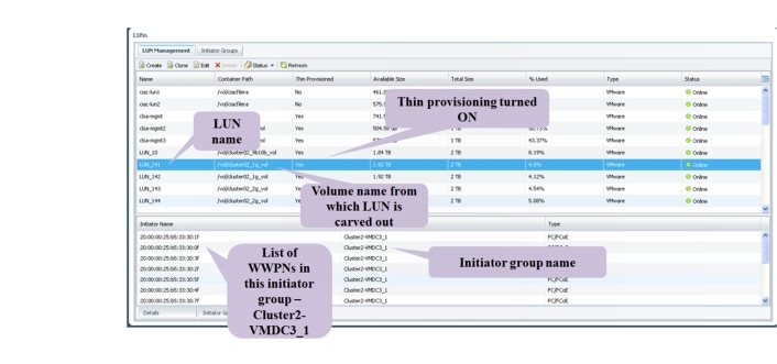
The LUN provides block-level storage to the server. The operating system (in this case, ESXi) is provided with a unique list of LUNs based on the server adapter WWPN. Each LUN is configured with a LUNID, that is commonly referred to as the Host LUNID (the ID that the host will use to access a particular LUN).
NAS Implementation Overview
Figure 2-15 provides an overview of the end-to-end storage infrastructure.
Figure 2-15 End-to-End Storage Infrastructure
The following is an end-to-end flow diagram from application (user VM) to storage using NFS infrastructure. The compute, network, and storage portions of the flow are shown separately.
Compute
Figure 2-16 shows how the different components of the compute layer are stacked up and the traffic that flows between them.
Figure 2-16 Compute Flow
Network
Figure 2-17 shows the L2 switch, which is a Nexus 5500 series switch. Both the Server (Host) and Storage (NetApp Filer FAS6040) are connected to this switch, which is a part of the ICS stack.
Figure 2-17 Network Flow
Storage
The storage filers used to provide NFS are the NetApp FAS6040, as shown in Figure 2-18.
Figure 2-18 Storage Flow
This section presents the following topics:
•![]() NFS from Fabric Interconnect to Nexus 5500
NFS from Fabric Interconnect to Nexus 5500
•![]() NFS from Nexus 5500 to FAS6040
NFS from Nexus 5500 to FAS6040
NFS from Fabric Interconnect to Nexus 5500
The salient features of the Network File System (NFS) configuration in the DC are as follows:
•![]() NFS traffic is isolated from other LAN traffic by using a separate VLAN.
NFS traffic is isolated from other LAN traffic by using a separate VLAN.
•![]() Configure the NFS VLAN on the Nexus 1000V, UCSM, and Nexus 5548 ICS switches. In this case, VLAN 1990 is chosen to be the NFS VLAN.
Configure the NFS VLAN on the Nexus 1000V, UCSM, and Nexus 5548 ICS switches. In this case, VLAN 1990 is chosen to be the NFS VLAN.
•![]() It is important to pin the NFS VLAN only on all of the uplinks in the data network (data uplinks are - Po88 and Po89). Refer to the end-to-end storage infrastructure diagram here). This configuration is done both on the UCSM and Nexus 1000V. This implies that the NFS VLAN must be blocked on the management network port-channels/uplinks.
It is important to pin the NFS VLAN only on all of the uplinks in the data network (data uplinks are - Po88 and Po89). Refer to the end-to-end storage infrastructure diagram here). This configuration is done both on the UCSM and Nexus 1000V. This implies that the NFS VLAN must be blocked on the management network port-channels/uplinks.
Below is an overview of the steps involved in NFS configuration on the UCS, FIs, and Nexus 5548 ICS switch.
1. ![]() To enable NFS connectivity, the ESX server requires a special connection type, referred to as a VMKernel port.
To enable NFS connectivity, the ESX server requires a special connection type, referred to as a VMKernel port.
2. ![]() Create a new VMKernel port on the ESXi host and allow the NFS VLAN. Configure an IP (in the NFS subnet) for the VMKernel port for every server blade that needs NFS connectivity.
Create a new VMKernel port on the ESXi host and allow the NFS VLAN. Configure an IP (in the NFS subnet) for the VMKernel port for every server blade that needs NFS connectivity.
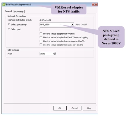
3. ![]() Configure an NFS VLAN port-group profile in Nexus 1000V.
Configure an NFS VLAN port-group profile in Nexus 1000V.
4. ![]() Allow the VLAN on the LAN port-channel between the UCS and Nexus 5548 ICS switch.
Allow the VLAN on the LAN port-channel between the UCS and Nexus 5548 ICS switch.
5. ![]() Mount the NFS filer on the VMware ESXi Host (configure the mount after finishing the configuration on NetApp filers).
Mount the NFS filer on the VMware ESXi Host (configure the mount after finishing the configuration on NetApp filers).
Below are snapshot diagrams that explain the details of the steps listed above. Figure 2-19 shows the configuration of the NFS VLAN in the UCSM.
Figure 2-19 NFS VLAN in the UCSM
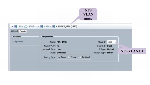
Figure 2-20 shows the configuration of the VMKernel interface, which is used by the server to establish NFS connectivity on the LAN.
Figure 2-20 VMKernel Interface
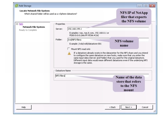
Assuming, that storage for NFS is set up (refer to NetApp FAS6040 - NFS for more details), Figure 2-21 provides an overview of NFS mount in the VMware vCenter.
Figure 2-21 NFS Mount in VMware vCenter
Below is the configuration of the NFS VLAN in the Nexus 1000V.
port-profile NFS_1990
type: Vethernet
description:
status: enabled
max-ports: 32
min-ports: 1
inherit:
config attributes:
switchport mode access
switchport access vlan 1990
service-policy input nfs
no shutdown
evaluated config attributes:
switchport mode access
switchport access vlan 1990
service-policy input nfs
no shutdown
assigned interfaces:
Vethernet1413
port-group: NFS_1990
system vlans: none
capability l3control: no
capability iscsi-multipath: no
capability vxlan: no
capability l3-vservice: no
port-profile role: none
port-binding: ephemeral
NFS from Nexus 5500 to FAS6040
This section provides an overview of the configuration required to establish NFS connectivity between the Nexus 5548 ICS switch and NetApp filers FAS6040. The salient features of NFS configuration are as follows:
•![]() In this implementation, NFS filers are in the same subnet as ESXi hosts (NFS clients). NFS traffic is carried in the same end-to-end VLAN (L2) between server blades and filers. In this implementation, we have NFS ESXi clients and storage in the same subnet as it minimizes latency (eliminates routing overhead) and reduces the number of hops.
In this implementation, NFS filers are in the same subnet as ESXi hosts (NFS clients). NFS traffic is carried in the same end-to-end VLAN (L2) between server blades and filers. In this implementation, we have NFS ESXi clients and storage in the same subnet as it minimizes latency (eliminates routing overhead) and reduces the number of hops.
•![]() NFS storage traffic between FIs and the Nexus 5500 is carried on the Ethernet port-channel, and traffic isolation is achieved using a separate VLAN (VLAN 1990), which is the same as the FCoE VLAN used for carrying NFS traffic from the UCS to the Nexus 5548 ICS switch.
NFS storage traffic between FIs and the Nexus 5500 is carried on the Ethernet port-channel, and traffic isolation is achieved using a separate VLAN (VLAN 1990), which is the same as the FCoE VLAN used for carrying NFS traffic from the UCS to the Nexus 5548 ICS switch.
•![]() NFS traffic between the Nexus 5500 and NetApp filers is sent on 10G links as Ethernet traffic. There is one Ethernet port-channel for every filer, which is connected to both the Nexus 5548 ICS switchs (as a vPC).
NFS traffic between the Nexus 5500 and NetApp filers is sent on 10G links as Ethernet traffic. There is one Ethernet port-channel for every filer, which is connected to both the Nexus 5548 ICS switchs (as a vPC).
The following configuration shows the Nexus 5548 ICS switch configuration of the vPC, which is connected to the Ethernet interface on the NetApp filer:
interface port-channel28
description vPC to netapp -B
switchport mode trunk
switchport trunk allowed vlan 1990
service-policy type queuing input vmdc-nas-in-policy
service-policy type queuing output vmdc-nas-out-policy
vpc 28
NetApp FAS6040—NFS
Figure 2-22 shows the end-to-end logical components within the NetApp FAS6040.
Figure 2-22 End-to-end Components within the NetApp FAS6040
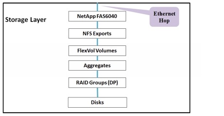
Starting from the bottom up, raw disks are formatted with a RAID group (in this case, RAID6) and grouped to form an Aggregate. From the Aggregate, volumes are carved out. Volumes are exported using the NFS protocol, and security rules are also applied on the volume (to selectively filter the clients accessing the NFS share and also assign authorization levels).
The following are the salient features of the NAS configuration on the NetApp FAS6040:
•![]() NFS volume that is exported must be given a security style, Unix or Windows depending on whether NFS or CIFS protocol is used.
NFS volume that is exported must be given a security style, Unix or Windows depending on whether NFS or CIFS protocol is used.
•![]() NFS uplinks to the Nexus 5548 ICS switch are bundled as a port-channel for link redundancy. A multi-mode VIF port-channel is created and uses the LACP protocol for efficient port-channel management.
NFS uplinks to the Nexus 5548 ICS switch are bundled as a port-channel for link redundancy. A multi-mode VIF port-channel is created and uses the LACP protocol for efficient port-channel management.
The following steps show an overview of the NFS storage configuration:
1. ![]() Configure Aggregates on the NetApp filer from physical disks and configure RAID-DP.
Configure Aggregates on the NetApp filer from physical disks and configure RAID-DP.
2. ![]() Configure volumes from Aggregates.
Configure volumes from Aggregates.
3. ![]() Start the NFS server using the nfs on CLI command.
Start the NFS server using the nfs on CLI command.
4. ![]() Configure the multi-mode VIF port-channel (uplinks) connected to the Nexus 5548 ICS switch. Below is the status of the VIF port-channel configured on one of the filers.
Configure the multi-mode VIF port-channel (uplinks) connected to the Nexus 5548 ICS switch. Below is the status of the VIF port-channel configured on one of the filers.
s6040a-vmdc> vif status
ifgrp: command "vif" is deprecated in favor of command "ifgrp"
default: transmit 'IP Load balancing', Ifgrp Type 'multi_mode', fail 'log'
ifgrp-199: 2 links, transmit 'IP+port Load balancing', Ifgrp Type 'lacp' fail
'default'
Ifgrp Status Up Addr_set
up:
e7b: state up, since 03Mar2013 22:11:38 (7+12:45:17)
mediatype: auto-10g_sr-fd-up
flags: enabled
active aggr, aggr port: e7a
input packets 1546529, input bytes 1164594806
input lacp packets 80171, output lacp packets 80603
output packets 876806, output bytes 139597180
up indications 213, broken indications 140
drops (if) 0, drops (link) 0
indication: up at 03Mar2013 22:11:38
consecutive 0, transitions 353
e7a: state up, since 06Feb2013 15:27:07 (32+19:29:48)
mediatype: auto-10g_sr-fd-up
flags: enabled
active aggr, aggr port: e7a
input packets 2745009, input bytes 2221709322
input lacp packets 100463, output lacp packets 100476
output packets 2261379, output bytes 697836908
up indications 9, broken indications 5
drops (if) 0, drops (link) 0
indication: up at 06Feb2013 15:27:07
consecutive 0, transitions 14
A virtual network interface (VIF) is a mechanism that supports aggregation of network interfaces into one logical interface unit. Once created, a VIF is indistinguishable from a physical network interface. VIFs are used to provide fault tolerance of the network connection, and in some cases, higher throughput to the storage device. Figure 2-23 shows the port-channel and VLAN formed using Ethernet interfaces on filers that provide NFS connectivity.
Figure 2-23 NFS Port-channel
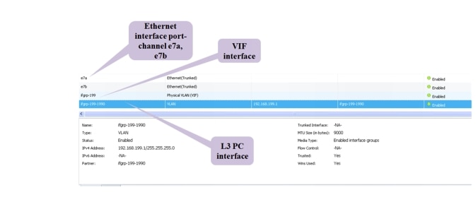
Note that the MTU configured on the NFS interface (shown in Figure 2-23) is 9000. It is mandatory to configure system jumbomtu 9216 on the ICS Cisco Nexus 5500 series switches to avoid MTU mismatch errors. Jumbo MTU size refers to the MTU size for L2 interfaces.
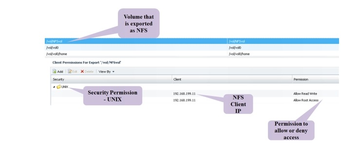
Select a volume for export using NFS. Figure 2-24 shows a volume exported as an NFS volume. Use exportfs to export the volume using NFS. The security permissions on this volume are Unix style, and also have the rules to allow/deny NFS client requests (from servers) based on the NFS IP address.
Figure 2-24 NFS Volume
NetApp FAS6040 Configuration Overview
VMDC 2.3 supports SAN or NAS storage options depending on the overall DC requirements. To ensure HA of storage, two FAS6040 filers are configured to operate in seven-mode cluster. They both run the same version of the ONTAP 8.1.1 operating system software. Each NetApp Fabric-Attached Storage (FAS) controller shares a NetApp Unified Storage Architecture based on the Data ONTAP 8G operating system and uses an integrated suite of application-aware manageability software. This efficiently consolidates SAN, NAS, primary storage, and secondary storage on a single platform while allowing concurrent support for block and file protocols by using Ethernet and FC interfaces. These interfaces include FCoE, Network File System (NFS), Common Internet File System protocol (CIFS), and Internet Small Computer System Interface (iSCSI).
The data disks are configured as a Redundant Array of Independent Disks (RAID) group with RAID-level Double Parity (RAID-DP) (NetApp high-performance RAID 6), which offers superior data protection with little or no performance loss. Data deduplication is enabled on volumes to increase storage efficiency by saving storage space. Thin Provisioning is enabled on all of the Logical Unit Numbers (LUNs) to maximize storage capacity utilization efficiency.
Figure 2-25 shows the configuration of Aggregates from data disks and configuration of RAID-DP.
Figure 2-25 NetApp Aggregate
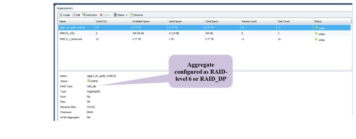
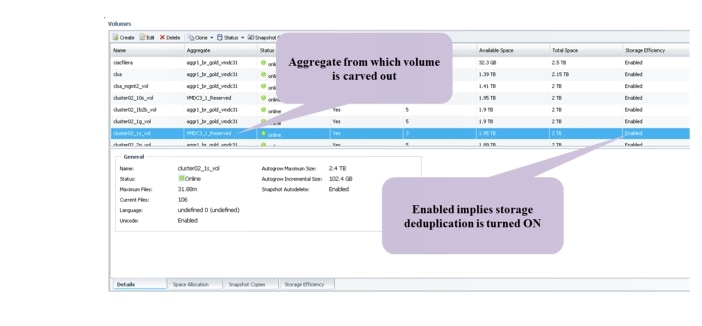
Figure 2-26 shows the configuration of volumes from a previously configured Aggregate.
Figure 2-26 NetApp Volumes
Hypervisor vSphere ESXi Implementation
The vSphere ESXi hypervisor is the workhorse for the compute infrastructure, providing the compute resources for hosting the VMs. Figure 2-27 shows the vSphere clusters, ESXi hosts, blade server assignments, and the tenants' distribution.
Figure 2-27 vSphere Clusters, ESXi Hosts, Blade Server Assignments, Tenants' Distribution
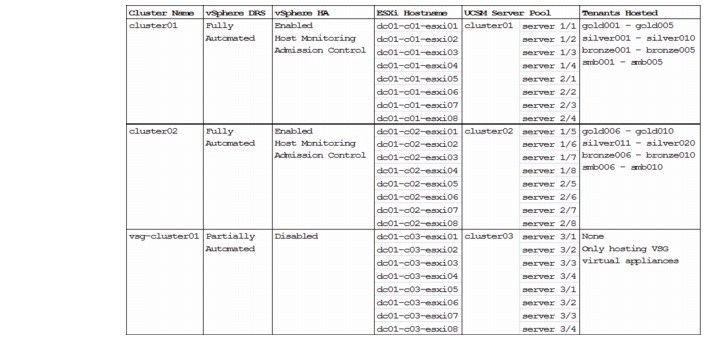
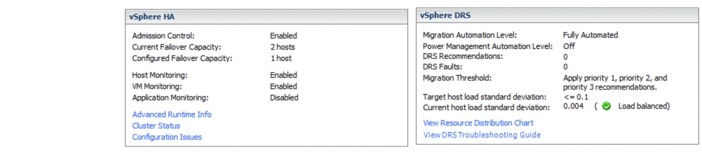
ESXi hosts in cluster01and cluster02 are used to host tenants' VMs. vSphere Distributed Resource Scheduling (DRS) is enabled to provide efficient load balancing of the computing workload across ESXi hosts in the cluster. vSphere HA is enabled to provide HA to the entire virtualized environment. Figure 2-28 shows the vSphere HA and DRS settings for cluster01 and cluster02.
Figure 2-28 vSphere HA and DRS for cluster01 and cluster02
ESXi hosts in the vsg-cluster01 are dedicated for hosting primary and secondary VSG virtual appliances. The VSG implements its own HA scheme, as such vSphere HA is not supported/required. The VSG does not support live vMotion, and vSphere DRS is set to partially automated for initial virtual appliance power on placement only.
vSphere Auto Deploy
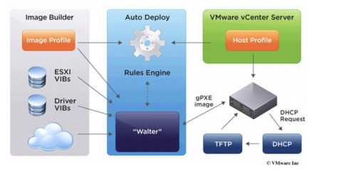
Beginning with version 5.0, vSphere provides the Auto Deploy option for the deployment of ESXi hosts. Auto Deploy uses a PXE boot infrastructure in conjunction with vSphere host profiles and an image builder to provision and customize the ESXi host. No state is stored on the ESXi host itself, instead, the Auto Deploy server manages state information for each ESXi host. Figure 2-29 shows the Auto Deploy architecture.
Figure 2-29 vSphere Auto Deploy Architecture
Note ![]() vSphere Auto Deploy is used for this implementation for deploying ESXi software to the blade servers. Alternatively, the ESXi hosts can also be configured to boot from SAN. Installing ESXi software on a locally attached disk is not recommended, as this breaks the stateless computing capabilities of UCS.
vSphere Auto Deploy is used for this implementation for deploying ESXi software to the blade servers. Alternatively, the ESXi hosts can also be configured to boot from SAN. Installing ESXi software on a locally attached disk is not recommended, as this breaks the stateless computing capabilities of UCS.
The following links provide more details about Auto Deploy and its installation and configuration:
•![]() http://kb.vmware.com/kb/2005131
http://kb.vmware.com/kb/2005131
•![]() http://blogs.vmware.com/vsphere/2012/01/understanding-the-auto-deploy-components.html
http://blogs.vmware.com/vsphere/2012/01/understanding-the-auto-deploy-components.html
•![]() http://pubs.vmware.com/vsphere-50/topic/com.vmware.vsphere.install.doc_50/GUIDCAB84194-3D8E-45F0-ABF9-0277710C8F98.html
http://pubs.vmware.com/vsphere-50/topic/com.vmware.vsphere.install.doc_50/GUIDCAB84194-3D8E-45F0-ABF9-0277710C8F98.html
•![]() http://kb.vmware.com/kb/2000988
http://kb.vmware.com/kb/2000988
•![]() http://www.cisco.com/en/US/solutions/collateral/ns340/ns517/ns224/ns944/ whitepaper_c11-701953.html
http://www.cisco.com/en/US/solutions/collateral/ns340/ns517/ns224/ns944/ whitepaper_c11-701953.html
Take the following into consideration when setting up Auto Deploy:
•![]() PXE support on the ESXi host network adapter is required.
PXE support on the ESXi host network adapter is required.
•![]() Auto Deploy makes use of PXE chainloading (http://etherboot.org/wiki/pxechaining) to load the gPXE bootloader to boot the ESXi host via HTTP (instead of TFTP; TFTP is used only to load the small gPXE bootloader). As such, upon booting, the ESXi host will request for IP information from the DHCP server twice with the same MAC address (first request from PXE, second request from gPXE). The DHCP server used must support such usage (most Linux DHCP servers do).
Auto Deploy makes use of PXE chainloading (http://etherboot.org/wiki/pxechaining) to load the gPXE bootloader to boot the ESXi host via HTTP (instead of TFTP; TFTP is used only to load the small gPXE bootloader). As such, upon booting, the ESXi host will request for IP information from the DHCP server twice with the same MAC address (first request from PXE, second request from gPXE). The DHCP server used must support such usage (most Linux DHCP servers do).
•![]() On the DHCP server, configure static binding of the MAC address to the IP address, ensuring that the ESXi host always gets the same IP address.
On the DHCP server, configure static binding of the MAC address to the IP address, ensuring that the ESXi host always gets the same IP address.
•![]() On newly deployed server hardware, make sure the BIOS clock is set correctly. If the BIOS clock is outdated by more than 60 days, the ESXi deployed on the server will not be able to join the vCenter.
On newly deployed server hardware, make sure the BIOS clock is set correctly. If the BIOS clock is outdated by more than 60 days, the ESXi deployed on the server will not be able to join the vCenter.
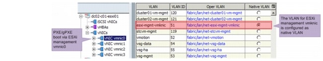
•![]() The PXE/gPXE bootloader does not support 802.1Q tagging of DHCP frames. Configure the VLAN where the ESXi management vmk interface resides as the native VLAN, as shown in Figure 2-30.
The PXE/gPXE bootloader does not support 802.1Q tagging of DHCP frames. Configure the VLAN where the ESXi management vmk interface resides as the native VLAN, as shown in Figure 2-30.
Figure 2-30 Configure Native VLAN for UCS Blade Server vNIC
•![]() Auto Deploy makes use of DNS. Configure both forward and reverse DNS resolution for the ESXi hostname on the DNS server. See http://blogs.vmware.com/vsphere/2012/11/auto-deployadding-host-to-vcenter-using-ip.html for more information.
Auto Deploy makes use of DNS. Configure both forward and reverse DNS resolution for the ESXi hostname on the DNS server. See http://blogs.vmware.com/vsphere/2012/11/auto-deployadding-host-to-vcenter-using-ip.html for more information.
•![]() Include up-to-date drivers' VIBs for the hardware on the server (ENIC, FNIC, etc.) to the Auto Deploy image profile used. Make sure to include the correct version of the drivers in accordance with the UCSM and vSphere versions.
Include up-to-date drivers' VIBs for the hardware on the server (ENIC, FNIC, etc.) to the Auto Deploy image profile used. Make sure to include the correct version of the drivers in accordance with the UCSM and vSphere versions.
•![]() If the ESXi hosts are part of the vSphere HA cluster, include the vmware-fdm VIB to the Auto Deploy image profile used. The vmware-fdm package can be retrieved from the software depot published by the vCenter server at the following URL: http://<VC-Address>/vSphere-HA-depot
If the ESXi hosts are part of the vSphere HA cluster, include the vmware-fdm VIB to the Auto Deploy image profile used. The vmware-fdm package can be retrieved from the software depot published by the vCenter server at the following URL: http://<VC-Address>/vSphere-HA-depot
•![]() For the UCS blade server with the Cisco VIC adapter (Cisco UCS VIC 1280, Cisco UCS VIC 1240, Cisco UCS M81KR VIC, etc.), the ESXi host boot time will be much longer than those with other adapters. See http://tools.cisco.com/Support/BugToolKit/search/getBugDetails.do? method=fetchBugDetails&bugId=CSCtu17983 for more details.
For the UCS blade server with the Cisco VIC adapter (Cisco UCS VIC 1280, Cisco UCS VIC 1240, Cisco UCS M81KR VIC, etc.), the ESXi host boot time will be much longer than those with other adapters. See http://tools.cisco.com/Support/BugToolKit/search/getBugDetails.do? method=fetchBugDetails&bugId=CSCtu17983 for more details.
•![]() The standard ESXi software package provisions the ESXi host with VMware Tools binaries. If network boot time or memory and storage overhead is a concern, Auto Deploy can provision the ESXi host without VMware Tools binaries. Refer to http://kb.vmware.com/kb/2004018 for details.
The standard ESXi software package provisions the ESXi host with VMware Tools binaries. If network boot time or memory and storage overhead is a concern, Auto Deploy can provision the ESXi host without VMware Tools binaries. Refer to http://kb.vmware.com/kb/2004018 for details.
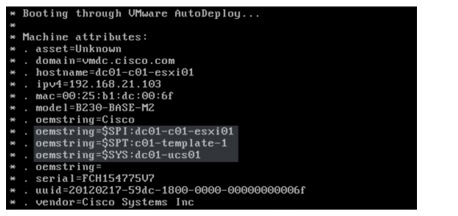
•![]() The UCS sets some OEM-specific strings in the SMBIOS to ease the configuration of Auto Deploy rules. The following oemstring is available (see Figure 2-31):
The UCS sets some OEM-specific strings in the SMBIOS to ease the configuration of Auto Deploy rules. The following oemstring is available (see Figure 2-31):
–![]() $SPI—Service-Profile Instance. The name of the service profile assigned to that specific blade server.
$SPI—Service-Profile Instance. The name of the service profile assigned to that specific blade server.
–![]() $SPT—Service-Profile Template. The name of the service profile template used to create that specific service profile.
$SPT—Service-Profile Template. The name of the service profile template used to create that specific service profile.
–![]() $SYS—System. The name of the UCSM system that manages the blade server.
$SYS—System. The name of the UCSM system that manages the blade server.
Figure 2-31 Cisco UCS oemstring in Auto Deploy
•![]() If the vCenter server, Auto Deploy server, DHCP server, or TFTP server are unavailable when the ESXi host boots up, the ESXi host will not be able to complete the boot and deployment process, rendering it unusable. Refer to https://blogs.vmware.com/techpubs/2012/03/highlyavailable-auto-deploy-infrastructure.html for recommendations on setting up highly available Auto Deploy infrastructure.
If the vCenter server, Auto Deploy server, DHCP server, or TFTP server are unavailable when the ESXi host boots up, the ESXi host will not be able to complete the boot and deployment process, rendering it unusable. Refer to https://blogs.vmware.com/techpubs/2012/03/highlyavailable-auto-deploy-infrastructure.html for recommendations on setting up highly available Auto Deploy infrastructure.
•![]() The Auto Deploy server is an HTTP server at its core. Simultaneously booting large numbers of ESXi hosts places a significant load on the Auto Deploy server. VMware recommends using existing web server scaling technologies to help distribute the load. Refer to http:// communities.vmware.com/groups/vsphere-autodeploy/blog/2012/04/20/scaling-out-autodeployusing-a-reverse-caching-proxy, which describes one way of scaling Auto Deploy with reverse caching proxy.
The Auto Deploy server is an HTTP server at its core. Simultaneously booting large numbers of ESXi hosts places a significant load on the Auto Deploy server. VMware recommends using existing web server scaling technologies to help distribute the load. Refer to http:// communities.vmware.com/groups/vsphere-autodeploy/blog/2012/04/20/scaling-out-autodeployusing-a-reverse-caching-proxy, which describes one way of scaling Auto Deploy with reverse caching proxy.
•![]() In ESXi version 5.0, the ESXi Network Dump Collector feature is supported only with Standard vSwitches and cannot be used on a VMkernel network interface connected to a vSphere Distributed Switch or Cisco Nexus 1000V Switch. See http://kb.vmware.com/kb/2000781 for more details.
In ESXi version 5.0, the ESXi Network Dump Collector feature is supported only with Standard vSwitches and cannot be used on a VMkernel network interface connected to a vSphere Distributed Switch or Cisco Nexus 1000V Switch. See http://kb.vmware.com/kb/2000781 for more details.
•![]() vCenter creates an associated scheduled task to check host-profile compliance when a new host profile is created. The default properties (run frequency, start time, etc.) for the scheduled task might not be suitable, make changes as appropriate.
vCenter creates an associated scheduled task to check host-profile compliance when a new host profile is created. The default properties (run frequency, start time, etc.) for the scheduled task might not be suitable, make changes as appropriate.
•![]() If a host profile that is saved from a reference host with the local SCSI-3 device, applying the host profile to another ESXi host will cause compliance failure. See http://kb.vmware.com/ kb/2002488 for more details.
If a host profile that is saved from a reference host with the local SCSI-3 device, applying the host profile to another ESXi host will cause compliance failure. See http://kb.vmware.com/ kb/2002488 for more details.
•![]() A newly created host profile, or a host profile that has been updated from a reference host, would overwrite some manually entered configuration with defaults. Make sure to edit the host profile after it has been created or updated from the reference host. The following settings are known to be overwritten:
A newly created host profile, or a host profile that has been updated from a reference host, would overwrite some manually entered configuration with defaults. Make sure to edit the host profile after it has been created or updated from the reference host. The following settings are known to be overwritten:
–![]() Networking configuration > Host virtual NIC > name of vmknic > Determine how the MAC address for vmknic should be decided.
Networking configuration > Host virtual NIC > name of vmknic > Determine how the MAC address for vmknic should be decided.
–![]() Security configuration > Administrator password.
Security configuration > Administrator password.
–![]() If the Enable/Disable Profile Configuration dialog box has been edited because of local SCSI-3 device described above, the changes will be overwritten as well.
If the Enable/Disable Profile Configuration dialog box has been edited because of local SCSI-3 device described above, the changes will be overwritten as well.
The following configuration shows the vSphere PowerCLI script used for Auto Deploy in this implementation:
# add ESXi packages
# download the offline image from http://www.vmware.com/patchmgr/download.portal
Add-EsxSoftwareDepot C:\temp\ESXi500-201209001.zip
# add HA package
Add-EsxSoftwareDepot http://192.168.13.14/vSphere-HA-depot/index.xml
# add Nexus1000v VEM package
# download the Nexus1000v image from VSM, http://<vsm-ip> Add-EsxSoftwareDepot
c:\temp\cisco-vem-v150-4.2.1.2.1.1.0-3.0.1.zip
# add enic driver for VIC adapter
Add-EsxSoftwareDepot c:\temp\enic_driver_2.1.2.22-offline_bundle-564611.zip
# add fnic driver for VIC adapter
Add-EsxSoftwareDepot c:\temp\fnic_driver_1.5.0.8-offline_bundle-758653.zip
# view the software depot Get-EsxSoftwareChannel
# remove all softweare depot
#Remove-EsxSoftwareDepot $DefaultSoftwareDepots
# view the image profile
Get-EsxImageProfile | select name
# view the available software packages Get-EsxSoftwarePackage
# clone a new image profile from existing profile, image profile with VMware Tools is
used
New-EsxImageProfile -CloneProfile ESXi-5.0.0-20120904001-standard -Name ESXi5-
b821926_n1kv-sv2.1.1_HA -Vendor vmdc
# add vmware HA package to the image profile
Add-EsxSoftwarePackage -ImageProfile ESXi5-b821926_n1kv-sv2.1.1_HA -SoftwarePackage
vmware-fdm
# add Nexus1000v VEM package to the image profile
Add-EsxSoftwarePackage -ImageProfile ESXi5-b821926_n1kv-sv2.1.1_HA -SoftwarePackage
cisco-vem-v150-esx
# add cisco enic driver package to the image profile
Add-EsxSoftwarePackage -ImageProfile ESXi5-b821926_n1kv-sv2.1.1_HA -SoftwarePackage
net-enic
# add cisco fnic driver package to the image profile
Add-EsxSoftwarePackage -ImageProfile ESXi5-b821926_n1kv-sv2.1.1_HA -SoftwarePackage
scsi-fnic
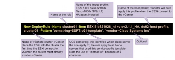
# create new deploy rule for ESXi host in cluster01
New-DeployRule -Name cluster01 -Item ESXi5-b821926_n1kv-sv2.1.1_HA, dc02-host-profile,
cluster01 -Pattern 'oemstring=$SPT:c01-template', "vendor=Cisco Systems Inc"
Add-DeployRule cluster01
# create new deploy rule for ESXi host in cluster02
New-DeployRule -Name cluster02 -Item ESXi5-b821926_n1kv-sv2.1.1_HA, dc02-host-profile,
cluster02 -Pattern 'oemstring=$SPT:c02-template', "vendor=Cisco Systems Inc"
Add-DeployRule cluster02
# create new deploy rule for ESXi host in cluster02
New-DeployRule -Name vsg-cluster01 -Item ESXi5-b821926_n1kv-sv2.1.1_HA,
dc02-hostprofile, vsg-cluster01 -Pattern 'oemstring=$SPT:c03-template', "vendor=Cisco
Systems Inc"
Add-DeployRule vsg-cluster01
Figure 2-32 shows the parameters of the vSphere PowerCLI New-DeployRule command.
Figure 2-32 vSphere PowerCLI New-DeployRule Command
Nexus 1000V Series Switches
The Nexus 1000V Series Switches provide a comprehensive and extensible architectural platform for VM and cloud networking. In this implementation, all networking needs of the VMs are provided by Nexus 1000V Series Switches.
Nexus 1010 Virtual Services Appliance
The Nexus 1000V Virtual Supervisor Module (VSM) HA-pair is hosted on an HA-pair of the Nexus 1010 VPN Services Adapter (VSA). The Nexus 1010 is configured with network uplink topology type 3. The following configuration shows the relevant Nexus 1010 configuration:
vlan 50
name mgmt
network-uplink type 3
interface GigabitEthernet1
interface GigabitEthernet2
interface GigabitEthernet3
interface GigabitEthernet4
interface GigabitEthernet5
interface GigabitEthernet6
interface PortChannel1
interface PortChannel2
virtual-service-blade dc02-n1kv01
virtual-service-blade-type name VSM-1.2
description dc02-n1kv01
interface control vlan 50
interface packet vlan 50
ramsize 2048
disksize 3
numcpu 1
cookie 1098716425
no shutdown primary
no shutdown secondary
interface VsbEthernet1/1
interface VsbEthernet1/2
interface VsbEthernet1/3
svs-domain
domain id 2381
control vlan 50
management vlan 50
svs mode L2
The Nexus 1000V VSM is configured in L3 SVS mode. All three interfaces of the VSM are configured in the same VLAN (VLAN ID 50).
Nexus 1000V Distributed Virtual Switch
Figure 2-33 depicts the Nexus 1000V deployment for this implementation. As shown in the figure, the Nexus 1000V Distributed Virtual Switch (DVS) is made up of the VSM HA-pair and the VEM/ESXi that the VSM control. For simplicity, the UCS FIs, UCS chassis, the upstream Nexus 5000 (tenants' data network), and Catalyst 6500 Virtual Switch System (VSS) (management network) switches are not shown in the diagram; only the components relevant to Nexus 1000V configuration are shown. Only two of the 24 ESXi/VEMs are shown in the diagram, and the other ESXi/VEM has similar configuration.
Figure 2-33 Nexus 1000V Network Layout

The Nexus 1000V VSM is configured in L3 SVS mode. In L3 SVS mode, VSM encapsulates the control and packet frames into User Datagram Protocol (UDP) packets. The VSM uses its mgmt0 interface to communicate with the VEMs. The VEMs are located in a different IP subnet from the VSM mgmt0 interface. On each VEM, the vmk0 vmkernel interface is used to communicate with the VSM. The following configuration shows the VSM svs-domain configuration:
svs-domain
domain id 2288
svs mode L3 interface mgmt0
Note ![]() Make sure that the SVS domain IDs for the Nexus 1010 VSA and Nexus 1000V VSM are unique. A domain ID is a parameter that is used to identify a VSM and VEM as related to one another.
Make sure that the SVS domain IDs for the Nexus 1010 VSA and Nexus 1000V VSM are unique. A domain ID is a parameter that is used to identify a VSM and VEM as related to one another.
The UCS is configured with disjoint upstream L2 networks; each ESXi/VEM host is configured with four NICs (also referred to as the ESXi VM Network Interface Card (VMNIC) or UCS vNIC), two
NICs for the management network (for UCS fabric A - fabric B redundancy), and two NICs for the tenants' data network (for UCS fabric A - fabric B redundancy). On the Nexus 1000V, two Ethernet uplink port profiles are configured. The following configuration shows the Ethernet port-profile configuration:
port-profile type ethernet system-mgmt-uplink
vmware port-group
port-binding static
switchport mode trunk
switchport trunk native vlan 51
switchport trunk allowed vlan 51-55,119-121
channel-group auto mode on mac-pinning
no shutdown
system vlan 51-55,119
state enabled
port-profile type ethernet system-data-uplink
vmware port-group
port-binding static
switchport mode trunk
switchport trunk allowed vlan 201-210,301-310,401-410,501-520,601-620
switchport trunk allowed vlan add 701-720,801-820,1601-1610,1801-1860
switchport trunk allowed vlan add 1990,2001-2010
channel-group auto mode on mac-pinning
no shutdown
state enabled
When the ESXi host is added to the Nexus 1000V DVS, the vmnic0 and vmnic1 interfaces are attached to the system-mgmt-uplink Ethernet uplink port profile, while the vmnic2 and vmnic3 interfaces are attached to the system-data-uplink Ethernet uplink port profile. For each VEM/ESXi added to the Nexus 1000V, the Nexus 1000V binds vmnic0 and vnmic1 into one MAC-pinning mode port-channel (to the management upstream network), while vmnic2 and vmnic3 are bound into another mac-pinning mode port-channel (to the tenants' data upstream network).
Note ![]() 1. The list of allowed VLANs configured on the two uplink Ethernet port profiles must not overlap. Defining two uplinks to carry the same VLAN is an unsupported configuration.
1. The list of allowed VLANs configured on the two uplink Ethernet port profiles must not overlap. Defining two uplinks to carry the same VLAN is an unsupported configuration.
2. The allowed VLANs list on each of the Ethernet port profiles should match what has been configured on the UCSM vNIC.
In this implementation, the vmknic ESXi kernel interfaces (vmk0 and vmk1) are also managed by the Nexus 1000V. The following shows the configuration used for the ESXi management and vMotion vmkernel interfaces respectively:
port-profile type vethernet esxi-mgmt-vmknic
capability l3control
vmware port-group
port-binding static
  switchport mode
access
switchport access vlan 51
pinning id 0
no shutdown
capability l3-vn-service
system vlan 51
max-ports 64
state enabled
port-profile type vethernet vmotion
vmware port-group
port-binding static
switchport mode access
switchport access vlan 52
pinning id 0
no shutdown
system vlan 52
max-ports 64
state enabled
Note the following:
•![]() The ESXi vmk0 interface is configured as the management interface and is attached to the esximgmt-vmknic vEthernet port profile.
The ESXi vmk0 interface is configured as the management interface and is attached to the esximgmt-vmknic vEthernet port profile.
•![]() The ESXi vmk1 interface is configured as the vMotion interface and is attached to the vmotion vEthernet port profile
The ESXi vmk1 interface is configured as the vMotion interface and is attached to the vmotion vEthernet port profile
•![]() Both port profiles are configured as the system port profile with the system vlan command. The VLANs in the vEthernet port profiles also have to be configured as the system VLAN in the Ethernet uplink port profile.
Both port profiles are configured as the system port profile with the system vlan command. The VLANs in the vEthernet port profiles also have to be configured as the system VLAN in the Ethernet uplink port profile.
•![]() The esxi-mgmt-vmknic port profile is configured with capability l3control, as the vmk0 interface is used for L3 control of the Nexus 1000V.
The esxi-mgmt-vmknic port profile is configured with capability l3control, as the vmk0 interface is used for L3 control of the Nexus 1000V.
•![]() The esxi-mgmt-vmknic port profile is also configured with capability l3-vn-service. L3 control of the VSG also uses the vmk0 interface.
The esxi-mgmt-vmknic port profile is also configured with capability l3-vn-service. L3 control of the VSG also uses the vmk0 interface.
Table 2-4 lists the port profiles configured for the tenants' VMs hosted on the compute infrastructure. For each tenant service class, only the port profiles for the first tenant are shown in the table, and the rest of the tenants for the same service class have similar configuration.
The configuration of the vEthernet port profile for tenants makes use of port-profile inheritance. Port-profile inheritance eases configuration and administration of setup with lots of port profiles. When properly deployed, inheritance enforces consist configuration across port profiles of similar nature. In this implementation, the tenants consist of Gold, Silver, Bronze, and SMB service classes. Tenants in the same service class have the same network requirements. Port-profile inheritance is used to ensure that each tenant in the same service class has the same network treatments. Tenants for Gold and Silver service classes are assigned with multiple port profiles, allowing their VMs to be placed in multiple VLANs.
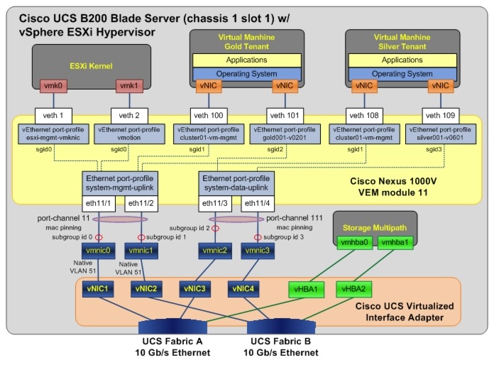
Figure 2-34 shows the Nexus 1000V VEM and its related UCS configuration details for one of the blade servers. The diagram depicts the subgroup ID pinning configured for the various port profiles.
Figure 2-34 Nexus 1000V Configuration Details
2.5 Compute and Storage Best Practices and Caveats
UCS Best Practices
•![]() When using UCSM configuration templates, be aware that some configuration changes will either cause server reboot or service disruption. Multiple templates of the same type should be used to prevent any single change to cause service disruption to all blade servers.
When using UCSM configuration templates, be aware that some configuration changes will either cause server reboot or service disruption. Multiple templates of the same type should be used to prevent any single change to cause service disruption to all blade servers.
•![]() When configuring server pools, select servers from multiple chassis to avoid single chassis failure bringing down all servers in the pool.
When configuring server pools, select servers from multiple chassis to avoid single chassis failure bringing down all servers in the pool.
•![]() Disable fabric failover for all vNICs configured for the blade servers, and let the Nexus 1000V manage the vNIC failure.
Disable fabric failover for all vNICs configured for the blade servers, and let the Nexus 1000V manage the vNIC failure.
•![]() UCSM does not support overlapping VLANs in disjoint L2 networks. Ensure that each VLAN only connects to one upstream disjoint L2 network.
UCSM does not support overlapping VLANs in disjoint L2 networks. Ensure that each VLAN only connects to one upstream disjoint L2 network.
•![]() UCS FI uses LACP as the port-channel aggregation protocol. The opposing upstream switches must be configured with LACP active mode.
UCS FI uses LACP as the port-channel aggregation protocol. The opposing upstream switches must be configured with LACP active mode.
•![]() A vNIC (VMNIC in the vSphere ESXi hypervisor or physical NIC in the bare metal server) can only communicate with one disjoint L2 network. If a server needs to communicate with multiple disjoint L2 networks, configure a vNIC for each of those networks.
A vNIC (VMNIC in the vSphere ESXi hypervisor or physical NIC in the bare metal server) can only communicate with one disjoint L2 network. If a server needs to communicate with multiple disjoint L2 networks, configure a vNIC for each of those networks.
•![]() UCSM implicitly assigns default VLAN 1 to all uplink ports and port-channels. Do not configure any vNICs with default VLAN 1. It is advisable not to use VLAN 1 for carrying any user data traffic.
UCSM implicitly assigns default VLAN 1 to all uplink ports and port-channels. Do not configure any vNICs with default VLAN 1. It is advisable not to use VLAN 1 for carrying any user data traffic.
Storage Best Practices
•![]() If using NetApp OnCommand System Manager 2.0 to configure storage filers, it is recommended to configure the following using the command line:
If using NetApp OnCommand System Manager 2.0 to configure storage filers, it is recommended to configure the following using the command line:
–![]() Configuring VIF and VLAN interfaces for NFS port-channel.
Configuring VIF and VLAN interfaces for NFS port-channel.
–![]() Configure security style (Unix or Windows) permissions when a volume is exported as NFS.
Configure security style (Unix or Windows) permissions when a volume is exported as NFS.
•![]() To take advantage of Thin Provisioning, it is recommended to configure Thin Provisioning on both volumes/LUNs in storage and in VMFS.
To take advantage of Thin Provisioning, it is recommended to configure Thin Provisioning on both volumes/LUNs in storage and in VMFS.
•![]() Configure Asymmetric Logical Unit Access (ALUA) on the filers for asymmetric logical unit access of LUNs.
Configure Asymmetric Logical Unit Access (ALUA) on the filers for asymmetric logical unit access of LUNs.
•![]() Enable storage deduplication on volumes to improve storage efficiency.
Enable storage deduplication on volumes to improve storage efficiency.
•![]() Nexus 5000 is the storage switch in this design. It is mandatory to enable NPIV mode on the Nexus 5000, and also configure soft zoning (enables server mobility) that uses WWPNs.
Nexus 5000 is the storage switch in this design. It is mandatory to enable NPIV mode on the Nexus 5000, and also configure soft zoning (enables server mobility) that uses WWPNs.
vSphere ESXi Best Practices
•![]() vSphere Auto Deploy makes use of PXE and gPXE. The PXE/gPXE bootloader does not support 802.1Q tagging of DHCP frames. Configure the VLAN where the ESXi management vmk interface resides as the native VLAN.
vSphere Auto Deploy makes use of PXE and gPXE. The PXE/gPXE bootloader does not support 802.1Q tagging of DHCP frames. Configure the VLAN where the ESXi management vmk interface resides as the native VLAN.
•![]() vSphere Auto Deploy makes use of DNS. Configure both forward and reverse DNS resolution for the ESXi hostname on the DNS server.
vSphere Auto Deploy makes use of DNS. Configure both forward and reverse DNS resolution for the ESXi hostname on the DNS server.
•![]() When using vSphere Auto Deploy, make sure that the vCenter server, Auto Deploy server, DHCP server, and TFTP server are made highly available.
When using vSphere Auto Deploy, make sure that the vCenter server, Auto Deploy server, DHCP server, and TFTP server are made highly available.
vSphere ESXi Caveats
•![]() For the UCS blade server with the Cisco VIC adapter (Cisco UCS VIC 1280, Cisco UCS VIC 1240, Cisco UCS M81KR VIC, etc.), the ESXi host boot time will be much longer than those with other adapters. See CSCtu17983 for more details.
For the UCS blade server with the Cisco VIC adapter (Cisco UCS VIC 1280, Cisco UCS VIC 1240, Cisco UCS M81KR VIC, etc.), the ESXi host boot time will be much longer than those with other adapters. See CSCtu17983 for more details.
•![]() In ESXi version 5.0, the ESXi Network Dump Collector feature is supported only with Standard vSwitches and cannot be used on a VMkernel network interface connected to a vSphere Distributed Switch or Nexus 1000V Switch. See VMware Knowledge Base for more details.
In ESXi version 5.0, the ESXi Network Dump Collector feature is supported only with Standard vSwitches and cannot be used on a VMkernel network interface connected to a vSphere Distributed Switch or Nexus 1000V Switch. See VMware Knowledge Base for more details.
Nexus 1000V Series Switches Best Practices
•![]() Make sure that the SVS domain IDs for the Nexus 1010 VSA and the Nexus 1000V VSM are unique.
Make sure that the SVS domain IDs for the Nexus 1010 VSA and the Nexus 1000V VSM are unique.
•![]() Configure port profiles for management and vMotion vmknic as system vlan.
Configure port profiles for management and vMotion vmknic as system vlan.
•![]() Make use of port-profile inheritance to enforce consistent configuration and ease of management.
Make use of port-profile inheritance to enforce consistent configuration and ease of management.
 Feedback