VMDC 2.3 Implementation Guide
Bias-Free Language
The documentation set for this product strives to use bias-free language. For the purposes of this documentation set, bias-free is defined as language that does not imply discrimination based on age, disability, gender, racial identity, ethnic identity, sexual orientation, socioeconomic status, and intersectionality. Exceptions may be present in the documentation due to language that is hardcoded in the user interfaces of the product software, language used based on RFP documentation, or language that is used by a referenced third-party product. Learn more about how Cisco is using Inclusive Language.
- Updated:
- April 8, 2013
Chapter: Overview
Implementation Overview
The cloud is the source of highly scalable, efficient, and elastic services accessed on-demand over the Internet or intranet. In the cloud, compute, storage, and network hardware are abstracted and delivered as a service. End users enjoy the functionality and value provided by the service without the need to manage the underlying technology. A cloud deployment model differs from traditional deployments in its ability to treat the Data Center (DC) as a common fabric of resources. A portion of these resources can be dynamically allocated and de-allocated when they are no longer in use.
The Cisco Virtualized Multiservice Data Center (VMDC) solution is the Cisco reference architecture for Infrastructure as a Service (IaaS) cloud deployments. This Cisco IaaS cloud architecture is designed around a set of modular DC components consisting of building blocks of resources called pods. A pod, or Point of Delivery, is comprised of the Cisco Unified Computing System (UCS), SAN and NAS storage arrays, Access (switching) layers, Aggregation (switching and routing) layers, Services layer devices (firewalls, load balancers), and multiple 10 GE fabric using highly scalable Cisco network switches and routers.
The VMDC solution utilizes compute and pod building blocks consisting of shared resource pools of network, compute, and storage components. Each of these components is virtualized and used by multiple tenants securely, so that each cloud tenant appears to have its own set of physical resources. Cloud service orchestration tools automate the resource provisioning workflow within the cloud DC. Orchestration leverages a set of tools and APIs to dynamically provision cloud resources on demand. The VMDC solution is targeted towards Enterprises building private clouds and Service Providers building IaaS public clouds and virtual private clouds. There have been several iterations of the VMDC solution, with each phase encompassing new platforms, versions, and technologies. The most recently released versions of VMDC are the VMDC 2.2 system release, which is based on traditional Layer 2 (L2) fabric architecture with Virtual Port-Channels (vPC), and the VMDC 3.0 system release, which is based on an extended L2 DC fabric utilizing Cisco FabricPath. Both systems utilize an end-to-end VRF-Lite Layer 3 (L3) model within the DC.
For more information about the VMDC solution, refer to the following documentation on Cisco.com Design Zone:
•![]() Cisco VMDC 2.2 Design Guide
Cisco VMDC 2.2 Design Guide
•![]() Cisco VMDC 2.2 Implementation Guide
Cisco VMDC 2.2 Implementation Guide
•![]() Cisco VMDC 3.0 Design Guide
Cisco VMDC 3.0 Design Guide
•![]() Cisco VMDC 3.0 Implementation Guide
Cisco VMDC 3.0 Implementation Guide
•![]() Cloud Ready Infrastructure Smart Solutions Kits Accelerate Design and Deployment of Unified DC
Cloud Ready Infrastructure Smart Solutions Kits Accelerate Design and Deployment of Unified DC
This document is the implementation guide for the VMDC 2.3 solution. The VMDC 2.3 architecture is based on the prior VMDC 2.2 architecture, with some major changes focusing optimizing the design to achieve higher tenancy scale, while lowering the cost and footprint of the solution. The key changes in the VMDC 2.3 solution are listed below.
•![]() Use of ASA and ACE services appliances to connect directly to the Aggregation layer Nexus 7000, instead of using service modules on the Catalyst 6500 Data Center Services Node (DSN).
Use of ASA and ACE services appliances to connect directly to the Aggregation layer Nexus 7000, instead of using service modules on the Catalyst 6500 Data Center Services Node (DSN).
•![]() Collapsed Core/Aggregation layer, instead of a separate core layer to interconnect Pods. The Pods will be interconnected through the DC-PE layer in VMDC 2.3.
Collapsed Core/Aggregation layer, instead of a separate core layer to interconnect Pods. The Pods will be interconnected through the DC-PE layer in VMDC 2.3.
•![]() Nexus 7004 with F2 module and SUP2 supervisor, as the Aggregation layer (Other Nexus 7000 form-factors and linecards can also be utilized).
Nexus 7004 with F2 module and SUP2 supervisor, as the Aggregation layer (Other Nexus 7000 form-factors and linecards can also be utilized).
•![]() Cisco Aggregation Services Router (ASR) 1006 as Data Center Provider Edge (DC-PE) (other ASR platforms or form-factors can also be utilized).
Cisco Aggregation Services Router (ASR) 1006 as Data Center Provider Edge (DC-PE) (other ASR platforms or form-factors can also be utilized).
•![]() Optimized tenancy models (Gold, Silver, Bronze network containers) to consume less resources (VRF, HSRP, VLAN, BGP etc) on the platforms, and thus provide higher tenancy scale.
Optimized tenancy models (Gold, Silver, Bronze network containers) to consume less resources (VRF, HSRP, VLAN, BGP etc) on the platforms, and thus provide higher tenancy scale.
•![]() Introduction of a Copper tenant container, with shared outside global routing and shared firewall context, but separate inside routing contexts. The Copper container is suitable for Internet-based cloud access for Small/Medium Business (SMB) customers, who typically require a few Virtual Machines (VMs) on a single VLAN.
Introduction of a Copper tenant container, with shared outside global routing and shared firewall context, but separate inside routing contexts. The Copper container is suitable for Internet-based cloud access for Small/Medium Business (SMB) customers, who typically require a few Virtual Machines (VMs) on a single VLAN.
This document is the implementation guide for the VMDC 2.3 solution. Refer to the Cisco VMDC 2.3 Design Guide for the design considerations that were used for this architecture.
This chapter presents the following topics:
Solution Architecture
The VMDC 2.3 solution utilizes a hierarchical network design for High Availability (HA) and scalability. The hierarchical or layered DC design uses redundant switches at each layer of the network topology for device-level failover that creates a highly available transport between end nodes using the network. DC networks often require additional services beyond basic packet forwarding, such as SLB, firewall, and intrusion prevention. These services might be introduced as modules populating a slot of one of the switching nodes in the network or as standalone appliance devices. Each service approach also supports the deployment of redundant hardware to preserve HA standards set by the network topology. This layered approach is the basic foundation of the VMDC design to provide scalability, performance, flexibility, resiliency, and service assurance. VLANs and Virtual Routing and Forwarding (VRF) instances are used to provide tenant isolation within the DC architecture, and routing protocols within the VRF instances are utilized to interconnect the different networking and service devices.
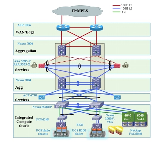
This multi-layered VMDC DC architecture is comprised of WAN, Core, Aggregation, Services, and Access layers. This architecture allows for DC modules to be added as demand and load increases. It also provides the flexibility to create different logical topologies utilizing device virtualization, the insertion of service devices, and traditional Layer 3 (L3) and L2 network configurations. The previous VMDC 2.0/2.2 architectures included all of the above layers. The VMDC 2.3 architecture has been optimized by utilizing a collapsed Core/Aggregation layer, so the architecture does not include a separate Core layer. Instead, the different pods in the VMDC 2.3 DC are interconnected at the WAN layer.
These layers in the VMDC 2.3 architecture are briefly described below.
•![]() WAN/Edge—The WAN or DC Edge layer connects the DC to the WAN. Typically, this provides IP or Multiprotocol Label Switching (MPLS)-based connectivity to the Internet or intranet. The ASR 1006 is used as an MPLS PE router in the VMDC 2.3 design, providing L3VPN connectivity to the provider IP/MPLS network. It also provides aggregation of all the DC pods as they connect directly to the ASR 1006 PE.
WAN/Edge—The WAN or DC Edge layer connects the DC to the WAN. Typically, this provides IP or Multiprotocol Label Switching (MPLS)-based connectivity to the Internet or intranet. The ASR 1006 is used as an MPLS PE router in the VMDC 2.3 design, providing L3VPN connectivity to the provider IP/MPLS network. It also provides aggregation of all the DC pods as they connect directly to the ASR 1006 PE.
•![]() Aggregation—The Aggregation layer of the DC provides a consolidation point where Access layer switches provide connectivity between servers for multi-tier applications and across the core of the network to clients residing within the WAN, Internet, or campus. The VMDC 2.3 design utilizes Nexus 7004 switches as the Aggregation layer. This Aggregation layer provides the boundary between L3 routed links and L2 Ethernet broadcast domains in the compute cluster, and is also the connection point for the DC Services layer (firewalls, load balancers, and so forth). A VRF sandwich design is used on the Nexus 7004 aggregation device to insert the firewall layer for Gold and Copper tenants. An Outside VRF instance on the aggregation Nexus 7004 interconnects the DC-PE to the Perimeter Firewall layer. An Inside VRF on the aggregation Nexus 7004 is used to connect the Firewall layer to the compute cluster. This inside VRF on the aggregation Nexus 7004 switch is the default gateway for the VMs. For Silver and Bronze tenants, a single VRF design is used, and each tenant has a VRF instance where the default gateway for the VMs is implemented.
Aggregation—The Aggregation layer of the DC provides a consolidation point where Access layer switches provide connectivity between servers for multi-tier applications and across the core of the network to clients residing within the WAN, Internet, or campus. The VMDC 2.3 design utilizes Nexus 7004 switches as the Aggregation layer. This Aggregation layer provides the boundary between L3 routed links and L2 Ethernet broadcast domains in the compute cluster, and is also the connection point for the DC Services layer (firewalls, load balancers, and so forth). A VRF sandwich design is used on the Nexus 7004 aggregation device to insert the firewall layer for Gold and Copper tenants. An Outside VRF instance on the aggregation Nexus 7004 interconnects the DC-PE to the Perimeter Firewall layer. An Inside VRF on the aggregation Nexus 7004 is used to connect the Firewall layer to the compute cluster. This inside VRF on the aggregation Nexus 7004 switch is the default gateway for the VMs. For Silver and Bronze tenants, a single VRF design is used, and each tenant has a VRF instance where the default gateway for the VMs is implemented.
•![]() Access—The Access layer of the network provides connectivity for server farm end nodes in the DC. The Nexus 5548 is utilized as the Access layer switch in the VMDC 2.3 design. The Nexus 5548 connects to multiple UCS fabrics - UCS 6200 Fabric Interconnects and UCS 5100 Blade Chassis with UCS B-series blade servers). Typically, the Nexus 5500, UCS Fabric-Interconnects, UCS Blade-Chassis along with storage resources are bundled together in Integrated Compute Stacks (ICS) such as the VCE Vblock and Cisco/NetApp FlexPod.
Access—The Access layer of the network provides connectivity for server farm end nodes in the DC. The Nexus 5548 is utilized as the Access layer switch in the VMDC 2.3 design. The Nexus 5548 connects to multiple UCS fabrics - UCS 6200 Fabric Interconnects and UCS 5100 Blade Chassis with UCS B-series blade servers). Typically, the Nexus 5500, UCS Fabric-Interconnects, UCS Blade-Chassis along with storage resources are bundled together in Integrated Compute Stacks (ICS) such as the VCE Vblock and Cisco/NetApp FlexPod.
•![]() Services—Network and security services such as firewalls, server load balancers, intrusion prevention systems, application-based firewalls, and network analysis modules are typically deployed at the DC Services layer. In the VMDC 2.3 design, these services are implemented by appliances connected directly to the aggregation Nexus 7004 switches. The SLB service is provided by one or more pairs of ACE 4710 appliances. A pair of ASA 5585-X security appliances connected to the Nexus 7004 aggregation switches provides firewall services. A pair of ASA 5555-X security appliances connected to the Nexus 7004 aggregation switches provides secure remote access (IPsec-VPN and SSL-VPN) services, enabling remote clients to securely connect to the cloud resources. In addition, the Cisco Virtual Services Gateway (VSG) working in conjunction with the Cisco Nexus 1000V Distributed Virtual Switch (DVS) provides security services in the Compute layer, thereby providing intra-VLAN and inter-VLAN protection to the VMs.
Services—Network and security services such as firewalls, server load balancers, intrusion prevention systems, application-based firewalls, and network analysis modules are typically deployed at the DC Services layer. In the VMDC 2.3 design, these services are implemented by appliances connected directly to the aggregation Nexus 7004 switches. The SLB service is provided by one or more pairs of ACE 4710 appliances. A pair of ASA 5585-X security appliances connected to the Nexus 7004 aggregation switches provides firewall services. A pair of ASA 5555-X security appliances connected to the Nexus 7004 aggregation switches provides secure remote access (IPsec-VPN and SSL-VPN) services, enabling remote clients to securely connect to the cloud resources. In addition, the Cisco Virtual Services Gateway (VSG) working in conjunction with the Cisco Nexus 1000V Distributed Virtual Switch (DVS) provides security services in the Compute layer, thereby providing intra-VLAN and inter-VLAN protection to the VMs.
•![]() Integrated Compute and Storage—This is the Compute and Storage block, such as FlexPod or Vblock. This typically consists of racks of compute based on UCS and storage, and have a pair of Nexus 5500 switches aggregating the connections out of the block. The Nexus 5500 Access switch within the ICS provides connectivity both for the LAN (via 10GE Ethernet links) and SAN (via dedicated FC links), and also connects to the storage for the ICS stack.
Integrated Compute and Storage—This is the Compute and Storage block, such as FlexPod or Vblock. This typically consists of racks of compute based on UCS and storage, and have a pair of Nexus 5500 switches aggregating the connections out of the block. The Nexus 5500 Access switch within the ICS provides connectivity both for the LAN (via 10GE Ethernet links) and SAN (via dedicated FC links), and also connects to the storage for the ICS stack.
•![]() Virtual Access—Access switch virtualization allows the function of the logical L2 Access layer to span multiple physical devices. The Nexus 1000V DVS running on top of the VMware ESXi hypervisor is used in the VMDC 2.3 design.
Virtual Access—Access switch virtualization allows the function of the logical L2 Access layer to span multiple physical devices. The Nexus 1000V DVS running on top of the VMware ESXi hypervisor is used in the VMDC 2.3 design.
The Compute and Storage layer in the VMDC 2.3 design has been validated with a FlexPod-aligned implementation using the following components:
•![]() Compute—Cisco UCS 6248 Fabric Interconnects (FIs) with UCS 5108 blade chassis populated with UCS B200 half-width blades. VMware vSphere 5.0 ESXi is the hypervisor for virtualizing the UCS blade servers.
Compute—Cisco UCS 6248 Fabric Interconnects (FIs) with UCS 5108 blade chassis populated with UCS B200 half-width blades. VMware vSphere 5.0 ESXi is the hypervisor for virtualizing the UCS blade servers.
•![]() SAN—Cisco Nexus 5500 switches provide Fibre Channel (FC) connectivity between the UCS compute blades and the NetApp FAS 6040 storage array.
SAN—Cisco Nexus 5500 switches provide Fibre Channel (FC) connectivity between the UCS compute blades and the NetApp FAS 6040 storage array.
Figure 1-1 provides a logical representation of the VMDC 2.3 architecture.
Figure 1-1 VMDC 2.3 Solution Architecture
Multitenancy and VRF Separation
Multitenancy refers to the virtualization or logical division of a shared pool of network, compute, and storage resources among multiple tenants or groups. This logical separation is used instead of requiring dedicated physical resources for each tenant, thereby reducing cost and increasing utilization of resources. In the Enterprise private cloud deployment model, the tenant is referenced as a department or business unit, such as engineering or human resources. In the public cloud deployment model, a tenant is an individual consumer, an organization within an Enterprise, or an Enterprise subscribing to the public cloud services. In either model, each tenant must be securely separated from other tenants because they share the virtualized resource pool.
In the VMDC 2.3 solution, VLANs and VRF instances are used to provide traffic isolation between tenants. Each tenant has its own VRF and associated set of VLANs and sub-interfaces. VRF instances allow multiple routing configurations in a single L3 switch using separate virtual routing tables. By default, communication between VRF instances is not allowed to protect the privacy of each tenant. Service appliances like the ASA and ACE are also virtualized into virtual contexts for each tenant to provide traffic isolation. VRF-Lite is used throughout the DC L3 domain to securely isolate the tenants. BGP is used as the routing protocol within the DC, interconnecting the tenant VRF instances on the DC layers/devices. Per-VRF Border Gateway Protocol (BGP) is configured between the WAN/ Edge ASR 1006 router and aggregation Nexus 7004 device. For Gold and Copper tenants, a VRF sandwich design is used, and there are static routes utilized between the firewall context and Nexus 7004 switch for routing between the ASA context to and from the inside as well as outside VRF instances.
Modular Building Blocks
VMDC 2.3 provides a scalable solution that can address the needs of small and large Enterprise and Service Provider cloud data centers. This architecture enables customers to select the design that best suits their immediate needs while providing a solution that can scale to meet future needs without re-tooling or re-designing the DC. This scalability is achieved using a hierarchical design with two different modular building blocks: Pod and Integrated Compute Stack (ICS).
Pod
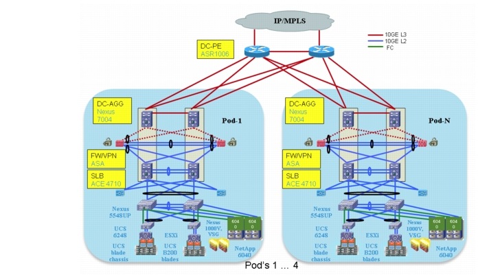
The modular DC design starts with a basic infrastructure module called a pod, which is a physical, repeatable construct with predictable infrastructure characteristics and deterministic functions. A pod identifies a modular unit of DC components and enables customers to add network, compute, and storage resources incrementally. This modular architecture provides a predictable set of resource characteristics (network, compute, and storage resource pools, power, and space consumption) per unit that is added repeatedly as needed.
In the VMDC 2.3 design, the Aggregation layer switch pair, Services layer nodes, and one or more integrated compute stacks are contained within a pod. The pod connects to the WAN/PE layer devices in the DC. To scale a pod, providers can add additional integrated compute stacks and can continue to scale in this manner until the pod resources are exceeded. To scale the DC, additional pods can be deployed and connected to the WAN layer devices.
Figure 1-2 illustrates how pods can be used to scale compute, network, and storage in predictable increments within the DC.
Figure 1-2 VMDC Pods for Scaling the Data Center
Integrated Compute Stack (ICS)
The second modular building block utilized is a generic ICS based on existing models, such as the VCE Vblock infrastructure packages or the Cisco/NetApp FlexPods. The VMDC 2.3 architecture is not limited to a specific ICS definition, but can be extended to include other compute and storage stacks.
An ICS can include network, compute, and storage resources in a repeatable unit. In this solution, storage and compute resources are contained within an ICS. To scale a pod, customers can add additional integrated compute stacks and can continue to scale in this manner until pod resources are exceeded. The storage and SAN resources within each pod can be interconnected to build a hierarchical storage area network.

Note ![]() The VMDC modular architecture has been designed to accommodate different types of iIntegrated compute stacks. Previous versions of VMDC have been validated with VCE Vblocks and Cisco/ NetApp FlexPods, and can support alternative ICS like Hitachi UCP, or other custom built compute stacks. While the VMDC 2.3 system can also accommodate Vblocks, FlexPods or other flavors of ICS, it has been validated with the Cisco/NetApp FlexPod.For more information on FlexPod, please refer to the following link.
The VMDC modular architecture has been designed to accommodate different types of iIntegrated compute stacks. Previous versions of VMDC have been validated with VCE Vblocks and Cisco/ NetApp FlexPods, and can support alternative ICS like Hitachi UCP, or other custom built compute stacks. While the VMDC 2.3 system can also accommodate Vblocks, FlexPods or other flavors of ICS, it has been validated with the Cisco/NetApp FlexPod.For more information on FlexPod, please refer to the following link.
Figure 1-3 illustrates how ICS can be used to scale the pod.
Figure 1-3 VMDC ICS for Scaling the Pod
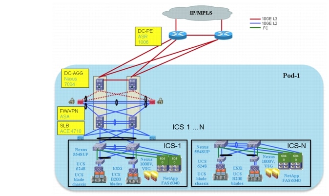
Table 1-1 lists some of the key architectural features of VMDC 2.3.
Service Tiers
Cloud providers, whether Service Providers or Enterprises, want an IaaS offering with multiple feature tiers and pricing levels. To tailor workload or application requirements to specific customer needs, the cloud provider can differentiate services with a multi-tiered service infrastructure and Quality of Service (QoS) settings. The Cisco VMDC architecture allows customers to build service level agreements that support their tenant or application requirements. Such services can be used and purchased under a variable pricing model. Infrastructure and resource pools can be designed so that end users can add or expand services by requesting additional compute, storage, or network capacity. This elasticity allows the provider to maximize the user experience by offering a custom, private DC in virtual form.
The VMDC 2.3 solution defines a reference multi-tier IaaS service model of Gold, Silver, Bronze, and Copper tiers. These service tiers define resource and service levels for compute, storage, and network performance. This is not meant to be a strict definition of resource allocation, but to demonstrate how differentiated service tiers could be built. These are differentiated based on the following features:
•![]() Network Resources—Differentiation based on network resources and features.
Network Resources—Differentiation based on network resources and features.
–![]() Application Tiers—Service tiers can provide differentiated support for application hosting. In some instances, applications may require several application tiers of VMs (web, application, database). VMDC 2.3 Gold and Silver services are defined with three application tiers on three separate VLANs to host web, application, and database services on different VMs. The Bronze and Copper service is defined with one VLAN only, so if there are multi-tiered applications, they must reside on the same VLAN or potentially on the same VM (Linux, Apache, MySQL, PHP, Perl, and Python (LAMP)/Windows Apache, MySQL, PHP, Perl, and Python (WAMP) stack).
Application Tiers—Service tiers can provide differentiated support for application hosting. In some instances, applications may require several application tiers of VMs (web, application, database). VMDC 2.3 Gold and Silver services are defined with three application tiers on three separate VLANs to host web, application, and database services on different VMs. The Bronze and Copper service is defined with one VLAN only, so if there are multi-tiered applications, they must reside on the same VLAN or potentially on the same VM (Linux, Apache, MySQL, PHP, Perl, and Python (LAMP)/Windows Apache, MySQL, PHP, Perl, and Python (WAMP) stack).
–![]() Access Methodsand Security—All four services, Gold, Silver, Bronze, and Copper, are defined with separate VRFs to provide security and isolation. Gold offers the most flexible access methods - over Internet, L3VPN, and secure VPN access over the Internet. Also, the Gold model has multiple security zones for each tenant. The Silver and Bronze models do not support any perimeter firewalling and only have VRF instances for isolation. The Copper model supports access over Internet, protected by a shared firewall to a private inside VRF per tenant.
Access Methodsand Security—All four services, Gold, Silver, Bronze, and Copper, are defined with separate VRFs to provide security and isolation. Gold offers the most flexible access methods - over Internet, L3VPN, and secure VPN access over the Internet. Also, the Gold model has multiple security zones for each tenant. The Silver and Bronze models do not support any perimeter firewalling and only have VRF instances for isolation. The Copper model supports access over Internet, protected by a shared firewall to a private inside VRF per tenant.
–![]() Stateful Services—Tenant workloads can also be differentiated by the services applied to each tier. The Gold service is defined with an ASA 5585-X virtual firewall, ACE 4710 Virtual Server Load Balancer (vSLB), and secure remote access (IPsec-VPN and SSLVPN) on the ASA 5555-X. The Silver tier is defined with an ACE 4710 vSLB. The Bronze tier is defined with no services. The Copper tier has a shared perimeter firewall across all tenants. In addition, for all four service tiers, security can be provided in the Compute layer by utilizing the VSG, in conjunction with the Nexus 1000V DVS.
Stateful Services—Tenant workloads can also be differentiated by the services applied to each tier. The Gold service is defined with an ASA 5585-X virtual firewall, ACE 4710 Virtual Server Load Balancer (vSLB), and secure remote access (IPsec-VPN and SSLVPN) on the ASA 5555-X. The Silver tier is defined with an ACE 4710 vSLB. The Bronze tier is defined with no services. The Copper tier has a shared perimeter firewall across all tenants. In addition, for all four service tiers, security can be provided in the Compute layer by utilizing the VSG, in conjunction with the Nexus 1000V DVS.
–![]() QoS—Bandwidth guarantee and traffic treatment can be a key differentiator. QoS policies can provide different traffic classes to different tenant types and prioritize bandwidth by service tier. The Gold tier supports VoIP/real-time traffic, call signalling and data class, while the Silver, Bronze, and Copper tiers have only data class. Additionally, Gold and Silver tenants are given bandwidth guarantee, with Gold getting more bandwidth (2x) than Silver.
QoS—Bandwidth guarantee and traffic treatment can be a key differentiator. QoS policies can provide different traffic classes to different tenant types and prioritize bandwidth by service tier. The Gold tier supports VoIP/real-time traffic, call signalling and data class, while the Silver, Bronze, and Copper tiers have only data class. Additionally, Gold and Silver tenants are given bandwidth guarantee, with Gold getting more bandwidth (2x) than Silver.
•![]() VM Resources—Service tiers can vary based on the size of specific VM attributes, such as CPU, memory, and storage capacity. The Gold service tier is defined with VM characteristics of 4 vCPU and 16 GB memory. The Silver tier is defined with VMs of 2 vCPU and 8 GB, while the Bronze and Copper tier VMs have 1 vCPU and 4 GB.
VM Resources—Service tiers can vary based on the size of specific VM attributes, such as CPU, memory, and storage capacity. The Gold service tier is defined with VM characteristics of 4 vCPU and 16 GB memory. The Silver tier is defined with VMs of 2 vCPU and 8 GB, while the Bronze and Copper tier VMs have 1 vCPU and 4 GB.
•![]() Storage Resources—To meet data store protection, the recovery point, or the recovery time objectives, service tiers can vary based on provided storage features, such as Redundant Array of Independent Disks (RAID) levels, disk types and speeds, and backup and snapshot capabilities. The Gold service is defined with 15k FC disks, the Silver tier on 10k FC disks, and the Bronze tier on Serial AT Attachment (SATA) disks.
Storage Resources—To meet data store protection, the recovery point, or the recovery time objectives, service tiers can vary based on provided storage features, such as Redundant Array of Independent Disks (RAID) levels, disk types and speeds, and backup and snapshot capabilities. The Gold service is defined with 15k FC disks, the Silver tier on 10k FC disks, and the Bronze tier on Serial AT Attachment (SATA) disks.
Figure 1-4 shows the three service tiers defined and validated in the VMDC 2.3 solution which are similar to the ones offered in VMDC2.2. Additionally, a Copper container is also offered, which has the same parameters as Bronze, but has only Internet-based access and no L3VPN-based access. These are reference service tiers that have been defined as part of the VMDC 2.3 reference architecture. Cloud providers can use this as a basis and define their own custom service tiers, based on their own deployment requirements.
Figure 1-4 VMDC 2.3 Service Tiers

The following tables provide details on the VMDC 2.3 three-tier service model. Table 1-2 depicts the network resource differentiation, Table 1-3 depicts the compute resource differentiation, and Table 1-4 depicts the storage resource differentiation.
Note ![]() This is a sample SLA that was validated in the testbed, based on the number of VMs, tenants, and link density.
This is a sample SLA that was validated in the testbed, based on the number of VMs, tenants, and link density.
Note ![]() Table 1-4 is shown as a sample representation of storage differentiation.
Table 1-4 is shown as a sample representation of storage differentiation.
VMDC 2.3 Gold Service
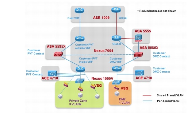
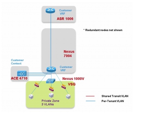
Figure 1-5 shows a logical representation of a VMDC 2.3 Gold service tier network container.
Figure 1-5 VMDC 2.3 Gold Service Tier Logical Topology—PVT VRF (Zone)
The network container is a logical (virtual) segment of the shared (common) physical network resources (end-to-end through the DC) that represents the DC network domain carrying tenant traffic. The physical infrastructure is common to all tenants, but each network device (routers, switches, firewalls, and so forth) is virtualized such that each tenant's virtual network container is overlaid on the common physical network.
The Gold tenant gets two network (and compute/storage) zones to place workloads into. Each zone has its own set of VLANs, VRF instances, and firewall/load balancer contexts. Figure 1-5 shows a logical representation of a two-zone VMDC 2.3 Gold network container.
This Gold service tier provides the highest level of sophistication by including secure remote access, firewall, and load balancing to the service. The vFW (on the ASA 5585-X60) provides perimeter security services, protecting tenant VMs. The vSLB (ACE 4710 appliance) provides load balancing across VMs in each tier of the tenant. The ASA 5555-X provides virtualized secure remote access (IPsec-VPN and SSL-VPN) to tenant VMs from the Internet. The ACE and ASA service module/ appliance are utilized in routed (L3) virtual mode in the VMDC 2.3 design. The Gold service tier also includes the Nexus 1000V VSG for providing virtual security services to the VMs. The Gold service provides higher QoS SLA and three traffic classes - real-time (VoIP), call signaling, and premium data.
The two zones can be used to host different types of applications, to be accessed through different network paths. The two zones are discussed in detail below.
•![]() PVT Zone. The PVT, or Private, Zone and its VMs can be used for cloud services to be accessed through the customer MPLS-VPN network. The customer sites connect to the provider MPLSCore and the customer has their own MPLS-VPN (Cust-VRF). The VMDC DC ASR 1000 PE connects to the customer sites through the MPLS-VPN (Cust-VRF in Figure 1-5). This CustVRF is extended through the VMDC network to the Nexus 7004 Aggregation switch. On the Agg/Access Nexus 7004, the Cust-VRF-outside connects to the ASA Cust-vFW, and then is connected back into a Cust-PVT-inside VRF on the Nexus 7004 Agg/Access device (VRF sandwich to insert service nodes), and then to the Compute layer on the UCS. For the VMDC 2.3 Gold tenant, the PVT zone is defined with three server VLANs. In addition, each tenant is assigned a separate Nexus 1000V VSG instance. The tenant is defined as an ORG in the VSG (VNMC), with the three VLANs placed into separate VSG sub-zones. The VSG is used to provide security policies to monitor and protect traffic between the VLANs (sub-zones).
PVT Zone. The PVT, or Private, Zone and its VMs can be used for cloud services to be accessed through the customer MPLS-VPN network. The customer sites connect to the provider MPLSCore and the customer has their own MPLS-VPN (Cust-VRF). The VMDC DC ASR 1000 PE connects to the customer sites through the MPLS-VPN (Cust-VRF in Figure 1-5). This CustVRF is extended through the VMDC network to the Nexus 7004 Aggregation switch. On the Agg/Access Nexus 7004, the Cust-VRF-outside connects to the ASA Cust-vFW, and then is connected back into a Cust-PVT-inside VRF on the Nexus 7004 Agg/Access device (VRF sandwich to insert service nodes), and then to the Compute layer on the UCS. For the VMDC 2.3 Gold tenant, the PVT zone is defined with three server VLANs. In addition, each tenant is assigned a separate Nexus 1000V VSG instance. The tenant is defined as an ORG in the VSG (VNMC), with the three VLANs placed into separate VSG sub-zones. The VSG is used to provide security policies to monitor and protect traffic between the VLANs (sub-zones).
•![]() DMZ Zone. The VMDC 2.3 Gold container supports a DMZ Zone for tenants to place VMs into a DMZ area, for isolating and securing the DMZ workloads from the PVT workloads, and also to enable users on the Internet to access the DMZ-based cloud services. The ASR 1000 PE WAN router is also connected to the Internet, and a shared (common) VRF (usually global routing table) exists for all Gold tenants to connect to (either encrypted or unencrypted). Encrypted (SSL or IPsec Remote Access VPN) traffic is sent to an ASA 5555-X, and based on the VPN policy, is mapped to a particular tenant and the corresponding tenant VPN VLAN. The tenant VPN VLAN then connects to the tenant DMZ-vFW (different vFW context on the ASA 5585-X than the tenant PVT-vFW), then to the tenant DMZ-VRF (different VRF on the Nexus 7004 Agg/ Access than the tenant PVT-VRF), and then to the Compute layer for the DMZ Zone. Similarly, unencrypted traffic from the Internet, based on the destination VM/VIP address, is sent to the tenant DMZ-vFW, then to the DMZ-vSLB, DMZ-VRF, and the DMZ Compute Zone. The DMZ Zone can be used to host applications like proxy servers, Internet-facing web servers, email servers, etc. The DMZ Zone consists of one server VLAN in this implementation.
DMZ Zone. The VMDC 2.3 Gold container supports a DMZ Zone for tenants to place VMs into a DMZ area, for isolating and securing the DMZ workloads from the PVT workloads, and also to enable users on the Internet to access the DMZ-based cloud services. The ASR 1000 PE WAN router is also connected to the Internet, and a shared (common) VRF (usually global routing table) exists for all Gold tenants to connect to (either encrypted or unencrypted). Encrypted (SSL or IPsec Remote Access VPN) traffic is sent to an ASA 5555-X, and based on the VPN policy, is mapped to a particular tenant and the corresponding tenant VPN VLAN. The tenant VPN VLAN then connects to the tenant DMZ-vFW (different vFW context on the ASA 5585-X than the tenant PVT-vFW), then to the tenant DMZ-VRF (different VRF on the Nexus 7004 Agg/ Access than the tenant PVT-VRF), and then to the Compute layer for the DMZ Zone. Similarly, unencrypted traffic from the Internet, based on the destination VM/VIP address, is sent to the tenant DMZ-vFW, then to the DMZ-vSLB, DMZ-VRF, and the DMZ Compute Zone. The DMZ Zone can be used to host applications like proxy servers, Internet-facing web servers, email servers, etc. The DMZ Zone consists of one server VLAN in this implementation.
In VMDC 2.3, a Gold tenant can choose to have only the PVT Zone, only the DMZ Zone, or both the PVT and DMZ Zones. If the tenant has both PVT and DMZ Zones, then the Gold tenant will consume three VRF instances (Cust-PVT-outside, Cust-PVT-inside, and Cust-DMZ), two VFW instances, two vSLB instances, two VSGs, and four server VLANs. To facilitate traffic flows between the DMZ and PVT Zones (for example, proxy or web servers in the DMZ Zone, application and database servers in the PVT Zone), the DMZ-vFW and PVT-vFW are interconnected, with the appropriate security policies.
Load-balanced traffic for all tiers of Gold tenants is implemented using the ACE 4710, which has one interface in each of the tiers.
The following cloud traffic services flows can be enabled in the VMDC 2.3 two-zone Gold service tier:
•![]() MPLS-VPN to PVT Zone
MPLS-VPN to PVT Zone
•![]() Unsecured (clear) Internet to DMZ Zone
Unsecured (clear) Internet to DMZ Zone
•![]() Secure (Remote Access SSL/IPsec VPN) Internet to DMZ Zone
Secure (Remote Access SSL/IPsec VPN) Internet to DMZ Zone
•![]() DMZ to PVT Zone
DMZ to PVT Zone
•![]() MPLS-VPN to DMZ Zone
MPLS-VPN to DMZ Zone
•![]() PVT to Internet Zone is via an HTTP proxy hosted in the DMZ Zone
PVT to Internet Zone is via an HTTP proxy hosted in the DMZ Zone
VMDC 2.3 Silver Service
Figure 1-6 shows a representation of a VMDC 2.3 Silver network container.
Figure 1-6 VMDC 2.3 Silver Service Tier Logical Topology
The Silver service tier includes one VRF instance per Silver tenant and three server VLANs (three-tiered applications) for each tenant. The Silver service includes a load-balancing service for more sophistication over the Bronze tier. The vLB (ACE 4710 appliance) provides load balancing across VMs in each tier of the tenant. The ACE service load balancer is utilized in one arm, routed (L3), virtual mode in the VMDC 2.3 design, and one context is used per Silver tenant. The context has links on each of the server VLANs and works in one-arm mode. The Silver service tier also includes the Nexus 1000V VSG to provide virtual security services to the VMs. The Silver service provides medium QoS SLA and one traffic class, premium data.
VMDC 2.3 Bronze Service
Figure 1-7 shows a representation of the VMDC 2.3 Bronze network container.
Figure 1-7 VMDC 2.3 Bronze Service Tier Logical Topology
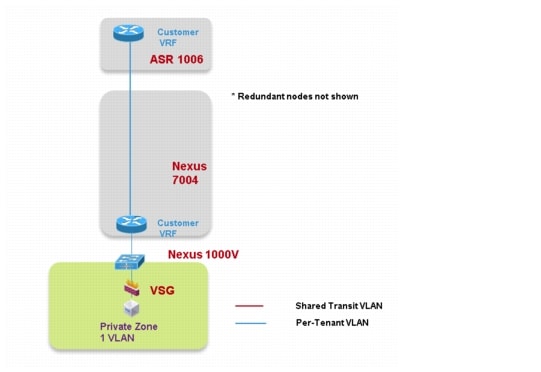
The Bronze service tier includes one VRF instance and one server VLAN for each tenant. The Bronze service is the least sophisticated tier and does not include any perimeter security services. The Bronze service tier does include the Nexus 1000V VSG for providing virtual security services to the VMs. The Bronze service provides lower QoS SLA and one traffic class, standard data.
VMDC 2.3 Copper/SMB Service
Figure 1-8 shows a representation of the VMDC 2.3 Copper network container.
Figure 1-8 VMDC 2.3 Copper Service Tier Logical Topology
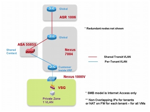
The Copper service tier, also referred to as the Small/Medium Business (SMB) tier, includes one VRF instance and one server VLAN for each tenant. The Copper service is the least sophisticated tier and shares a single firewall context with all other Copper tenants for access from the outside interface connecting to the Internet. The inside interface for each tenant is connected to a VRF per tenant, and server VLANs are connected to these VRF instances. This allows multiple VLANs for tenants if required. The Copper service tier does include the Nexus 1000V VSG to provide virtual security services to the VMs. The Copper service provides the lowest QoS SLA and one traffic class, standard data.
Solution Components
The VMDC 2.3 solution comprises a collection of Cisco and third-party hardware, software and management components. Table 1-5 highlights the components validated as part of the VMDC 2.3 solution.
Table 1-4 lists the component versions validated as part of the VMDC 2.3 solution, which is a reference architecture consisting of a set of hardware and software components that have been validated together at a point of time. It is possible that by the time customers are ready to deploy a VMDC 2.3-based cloud DC, some of these hardware and software versions could be end-ofsale or end-of-life, or there could be newer versions of these available and recommended by the product teams. In such situations, the newer or recommended releases or platforms should be used for deployments.
Note ![]() 1. The VMDC 2.3 solution was validated with the ASA 55555-X for IPsec and SSL VPN remote access. For higher performance and throughput, you can also use the ASA 5585-X with SSP-60.
1. The VMDC 2.3 solution was validated with the ASA 55555-X for IPsec and SSL VPN remote access. For higher performance and throughput, you can also use the ASA 5585-X with SSP-60.
2. The NetApp FAS6040 is used as the SAN storage array in the VMDC 2.3 compute pod to host production (data) VMs. The NetApp FAS3240 is used in the VMDC 2.3 management pod to host management VMs (VMware Virtual Center, Nexus 1000V VSM, VNMC, test tools, BMC CLM orchestration applications, and other management applications).
 Feedback