Cisco SD-WAN Large Global WAN Design Case Study
Available Languages
Bias-Free Language
The documentation set for this product strives to use bias-free language. For the purposes of this documentation set, bias-free is defined as language that does not imply discrimination based on age, disability, gender, racial identity, ethnic identity, sexual orientation, socioeconomic status, and intersectionality. Exceptions may be present in the documentation due to language that is hardcoded in the user interfaces of the product software, language used based on RFP documentation, or language that is used by a referenced third-party product. Learn more about how Cisco is using Inclusive Language.
- US/Canada 800-553-2447
- Worldwide Support Phone Numbers
- All Tools
 Feedback
 Feedback
Bank of the Earth Company Background and Legacy Network
Network Topology (Fabric and Service VPN Data Planes)
Data Center Head-End SD-WAN Router Design
SD-WAN Controller OMP Route Calculations
SD-WAN Controller Server Layout and IP Addressing
Appendix A: Changes from Previous Versions
Appendix C: Alternative SD-WAN Controller Design
Appendix D: SD-WAN Controller Affinity Deep-Dive
Appendix E: Examples for Calculating OMP Routes (RIB-in & RIB-out) in a Deployment
The designs discussed within this document are presented in the form of a case study for a fictional large global WAN customer – Bank of the Earth. Bank of the Earth is not a real customer and the network discussed within this document is not a real network. However, the designs presented within this guide are based on actual customer deployments. The purpose of this document is to present some of the considerations that a network engineer will need to focus attention upon and address when designing and implementing a large Cisco Catalyst SD-WAN deployment.
This guide is intended to provide technical guidance around the concepts required for the design of a large global WAN using Cisco Catalyst SD-WAN technology.
Audience
The audience for this document includes network design engineers, network operations personnel, and security operations personnel who wish to implement Cisco Catalyst SD-WAN networks.
Bank of the Earth Company Background and Legacy Network
Bank of the Earth is a large multi-national commercial and retail bank with branches located throughout Europe (EMEA) and North America (Americas). Their legacy network is based upon a combination of MPLS Layer3 VPN (wired or private LTE/5G) and Dynamic Multi-point VPN (DMVPN) over Internet technologies.
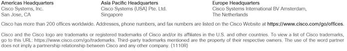
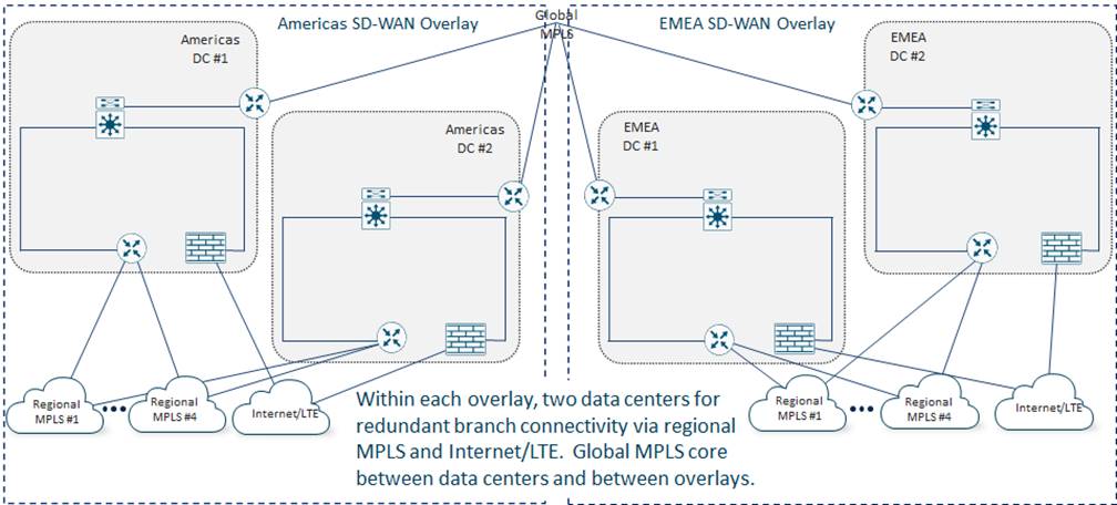
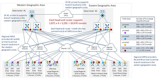
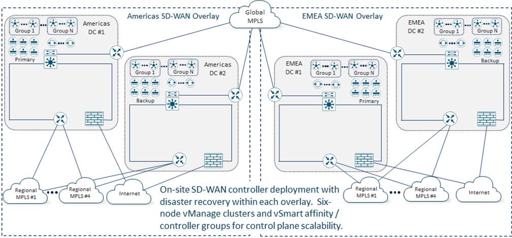
Bank of the Earth uses a traditional global MPLS carrier core to connect four main data center sites – two located in Europe (EMEA DC#1 and EMEA DC#2) and two located in North America (Americas DC#1 and Americas DC#2). Due to the business criticality of Bank of the Earth’s financial applications, redundant data centers are maintained within each geographic area (Americas and EMEA) – each capable of supporting all the branch locations within their respective geographic areas.
Bank of the Earth’s legacy network design is largely the result of acquisitions and mergers over the years. For example, Bank of the Earth originally had data center and branch sites only on the western side of the Americas. Through mergers and acquisitions, they acquired branch and data center sites on the eastern side of the Americas. Then, through consolidation Bank of the Earth was able to reduce the number of data centers to two – one geographically located within the western side of the Americas, which primarily services branches on the western side; and one on geographically located within the eastern side of the Americas, which primarily services branches on the eastern side. A similar growth pattern occurred in EMEA.
Up to four regional MPLS carriers connect branch sites to both data centers within each geographic area (EMEA and the Americas). Again, this is largely the result of mergers and acquisitions over the years. For example, regional MPLS providers #1 and #2 primarily service branch locations in the western side of the Americas, while regional MPLS providers #3 and #4 primarily service branch locations in the eastern side of the Americas. Since MPLS contracts are often long-term, spanning multiple years, Bank of the Earth has yet to consolidated to a smaller set of regional MPLS carriers. DMVPN over Internet connectivity is also used between some branch locations and the data centers within their respective geographic areas.
The following figure provides a high-level overview of Bank of the Earth’s legacy network.
Branch Design
Bank of the Earth has slightly under 10,800 branch sites overall. Branch sites vary considerably in size and design.
Large / Regional Branch Sites have dual active circuits from different regional MPLS carriers, with Internet (wired broadband or public LTE/5G) connectivity on both routers to provide additional bandwidth and an additional layer of high availability. Bank of the Earth has made the business decision that Large /Regional Branch Sites are business critical to their operations, and therefore require the deployment of dual routers for WAN access.
Medium-Sized Branch Sites typically have either one MPLS circuit from a regional carrier along with Internet (wired broadband or public LTE/5G) connectivity, or dual MPLS circuits from two regional carriers. In either scenario, both circuits are actively used. Bank of the Earth has made the business decision that the criticality of Medium-Sized Branch Sites does not warrant dual routers. Instead, a strategy for rapid replacement of networking equipment has been adopted for these sites. Hence, only a single router is deployed in Medium-Sized Branch Sites.
Small Branch Sites vary widely from a single ATM co-located within a larger retail site, such as a grocery store; to a small kiosk, which offers limited financial services, located within a shopping mall. Generally, a single circuit – either MPLS or Internet (wired broadband or LTE/5G) – is provisioned, depending upon what was available at the site. Bank of the Earth has made the business decision that the criticality of Small Branch Sites is low, and therefore does not warrant even dual circuits. A single router with integrated switch ports is typically deployed within Small Branch Sites. Where the number of required switch ports exceeds the number of ports on the integrated switch, a small standalone Layer 2 switch may be deployed along with the router.
The following table shows the distribution of Large / Regional, Medium-Sized, and Small Branch Sites within the Bank of the Earth network.
Table 1. Branch Sizes within the Bank of the Earth Network
| Branch or Data Center |
Americas Sites |
EMEA Sites |
Total Sites |
Routers Per Site |
Americas Routers |
EMEA Routers |
Total Routers |
Circuits per Site |
| Large / Regional |
596 |
596 |
1,192 |
2 |
1,192 |
1,192 |
2,384 |
4 |
| Medium-Sized |
2,300 |
2,300 |
4,600 |
1 |
2,300 |
2,300 |
4,600 |
2 |
| Small |
2,500 |
2,500 |
5,000 |
1 |
2,500 |
2,500 |
5,000 |
1 |
| Data Center |
2 |
2 |
4 |
4 |
8 |
8 |
16 |
5 |
| Total |
5,398 |
5,398 |
10,796 |
--- |
6,000 |
6,000 |
12,000 |
--- |
| Technical Note: |
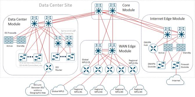
| For brevity, the two sides of the network (Americas and EMEA) within the Bank of the Earth case study are considered identical. In other words, the number of branch and data center sites, number of devices per site, number of circuits per site, etc., are the same for both sides of the network. Even the design of each of the data centers is considered identical. In actual production deployments this will likely not be the case. However, by assuming both sides are identical, much of the redundancy of having to repeat information can be eliminated. Within this case study, each side of the Bank of the Earth network (Americas and EMEA) translates to a separate SD-WAN overlay. Hence, the discussion within this guide will be focused primarily on one SD-WAN overlay – with the assumption that the design principles discussed for one overlay can be equally applied to the other overlay. Again, this is done to reduce the amount of information that has to be duplicated within this case study. In a real deployment, each SD-WAN overlay would have to be designed separately. |
Data Center Design
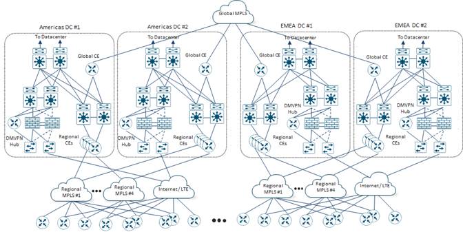
The following figure shows the general layout of one of the Data Center sites showing the legacy connectivity before migrating to SD-WAN.
Each Data Center Site consists of separate Core, Data Center, WAN Edge, and Internet Edge functional blocks / modules which connect to form a traditional hierarchical LAN design. Each Data Center Site is connected to all the regional MPLS carriers within its geographic area (Americas or EMEA), as well as the Bank of the Earth global MPLS backbone through the WAN Edge module. Each Data Center Site also has Internet connectivity, which is used for outbound Internet connectivity from the data center and branch sites, as well as for Internet-based DMVPN connections to some branch sites. The data center functional block / module within the Data Center site houses on-prem compute as well as a DCI link between Data Center Sites within the geographic area (Americas or EMEA).
As legacy router platforms within branch locations began to reach their end-of-life, Bank of the Earth made the business decision to migrate to SD-WAN simultaneously with refreshing their aging router platforms. The primary motivation for migrating to SD-WAN was centralized configuration and policy management, which would offset the need for additional staff to continue to deploy and maintain Bank of the Earth’s overall wide-area network. Additional benefits identified by Bank of the Earth were the Application Visibility (AV) and Application Aware Routing (AAR) features of Cisco Catalyst SD-WAN, which could be leveraged to make optimal use of bandwidth to sites with multiple MPLS and/or Internet transports. Finally, the future benefits of integration with cloud-based security services via Secure Access Service Edge (SASE), as well as Direct Internet Access (DIA) from the branch for Software-as-a-Service (SaaS) applications and guest access were a consideration.
The overall Bank of the Earth Cisco Catalyst SD-WAN deployment consists of two overlays based on geographic area – EMEA and the Americas.
This design choice aligns with the location of their data centers – two in Europe and two in North America – as well as the existing connectivity of branch sites to their respective data centers through regional MPLS carriers within each geographic area.
The primary drivers for the decision to go with two overlays were as follows:
● Since the total number of branch sites within Bank of the Earth’s network is approximately 10,800, the total number of SD-WAN devices required within the branch sites alone exceeds the number of devices currently supported by a single Cisco Catalyst SD-WAN overlay.
| Technical Note: |
| Guidance as to server size recommendations, as well as the maximum number of devices supported per SD-WAN overlay based upon the software release, can be found at the following link: https://www.cisco.com/c/en/us/td/docs/routers/sdwan/release/notes/compatibility-and-server-recommendations/ch-server-recs-20-9-combined.html |
● Each SD-WAN overlay defines a separate fault-domain within their overall network deployment. SD-WAN devices within an overlay rely on the centralized control and management planes provided by the SD-WAN Manager, SD-WAN Controllers and SD-WAN Validators. Hence, implementing multiple overlays constrains each fault-domain to a smaller number of SD-WAN devices within a smaller geographic area.
● Fewer SD-WAN devices within each overlay results in fewer OMP routes per overlay. This can result in lower CPU and memory load on each of the SD-WAN Controllers within the overlay.
● Fewer SD-WAN devices and sites within each overlay can result in smaller centralized policy per overlay. Smaller centralized policy and fewer SD-WAN Controllers per overlay due to fewer SD-WAN routers per overlay, can result in faster deployment and/or modifications to centralized policy within the overlay. Bank of the Earth needed to make sure the policy push times fit within the scheduled change windows allowed for network changes.
● Fewer SD-WAN routers within each overlay can result in lower SAIE (formerly known as DPI) / statistics collection per overlay. This can result in lower load in terms of CPU and memory on the SD-WAN Manager instances within each cluster, as well as longer storage times (in terms of days and/or weeks) that the statistics are available for viewing within SD-WAN Manager.
● Fewer SD-WAN routers within each overlay can result in lower number of API calls needed to troubleshoot and monitor the SD-WAN devices within the overlay. This can result in lower load, in terms of CPU utilization required on each SD-WAN Manager instance within the cluster needed to service the API calls.
Bank of the Earth also recognizes the complications associated with the choice of implementing two overlays:
● Two separate overlays must be managed, including creating and maintaining separate templates and/or profiles for SD-WAN devices within each overlay; as well as separate policies which must be configured and managed within the SD-WAN Manager cluster within each overlay. In other words, there is no single management pane of glass with multiple overlays.
● There is no end-to-end application visibility and/or statistics collection between overlays within SD-WAN Manager. If Bank of the Earth desires end-to-end application visibility and/or statistics they can use functionality such as the collection and export of flow data via NetFlow to 3rd party tools, such as LiveAction. Alternatively, they can leverage the APIs within SD-WAN Manager to periodically export data to 3rd party tools which can provide a consolidated view of application visibility and/or statistics across their overall network deployment.
● Segmentation via Service VPNs can be implemented within each SD-WAN overlay. However, Bank of the Earth must extend segmentation across the global MPLS network if they wish to maintain segmentation between overlays.
● There is additional cost in terms of physical servers needed to run two sets of SD-WAN control components (primary and backup SD-WAN Manager clusters, in addition to SD-WAN Controllers and SD-WAN Validators) within each overlay.
Despite the complications associated with implementing separate overlays, Bank of the Earth decided that the benefits of greater scale, potentially smaller centralized policy and faster policy push, and smaller fault domains outweighed the benefits of a single management pane of glass, additional work needed to extend segmentation across the global MPLS network, and additional cost of physical servers.
Bank of the Earth also actively monitors the status and health of each of the SD-WAN overlays, including CPU load and memory usage on each of the SD-WAN Manager and SD-WAN Controller instance, number of routes received and sent by each SD-WAN Controller instance, how long it takes to deploy policy and make configuration changes to their network, etc. This is used to determine if each existing SD-WAN overlay needs to be further split into multiple overlays – each with fewer SD-WAN devices – at some point in the future, to maintain their performance and scale targets.
Network Topology (Fabric and Service VPN Data Planes)
The primary data flow pattern within Bank of the Earth’s legacy network was client-server based. Devices owned, managed, and located within Bank of the Earth branch sites, access applications running on servers within the on-prem data centers in each of their respective geographic areas. Bank of the Earth saw no reason why the data flow patterns would be any different when migrating to an SD-WAN network infrastructure. Hence, the client-server data flow pattern favored the deployment of a hub-and-spoke fabric data plane topology within each SD-WAN overlay.
With a hub-and-spoke fabric data plane topology each branch site only forms persistent SD-WAN tunnels to the head-end routers located within the data center hub sites, and not with other branch sites. Since each Service VPN relies on the underlying fabric data plane topology, a hub-and-spoke fabric data plane topology implies that the data plane topology of each Service VPN is also hub-and-spoke.
In a hub-and-spoke fabric data plane topology, each branch router only needs to form one SD-WAN tunnel to each of the head-end routers within each data center, for each WAN transport (VPN 0) tunnel interface / TLOC – assuming the use of color restriction between TLOCs. This can allow for the deployment of router platforms that support fewer overall SD-WAN tunnels at the branch sites. Within a hub-and-spoke fabric data plane topology, it is only the head-end routers within the data centers which must be sized appropriately to support large numbers of SD-WAN tunnels.
Referring to Table 1 above, the number of branch routers within each overlay is just under 6,000. Bank of the Earth concluded that the number of SD-WAN tunnels required to form a full-mesh within each SD-WAN overlay would exceed the maximum number of tunnels supported by the router platforms they were targeting for the branch locations. A larger router platform could be deployed within each branch site, but that would exceed the price-point they were targeting for the branch locations. Therefore, Bank of the Earth made the decision to implement a hub-and-spoke fabric data plane topology within each SD-WAN overlay.
Hierarchical SD-WAN Consideration
As part of the SD-WAN initiative, Bank of the Earth considered re-designing the network infrastructure within each SD-WAN overlay to be based on multiple smaller regions, hierarchically connected to an SD-WAN backbone. This would require the deployment of a multi-region fabric Cisco Catalyst SD-WAN design (also known as a hierarchical SD-WAN design) – as shown in the following figure.
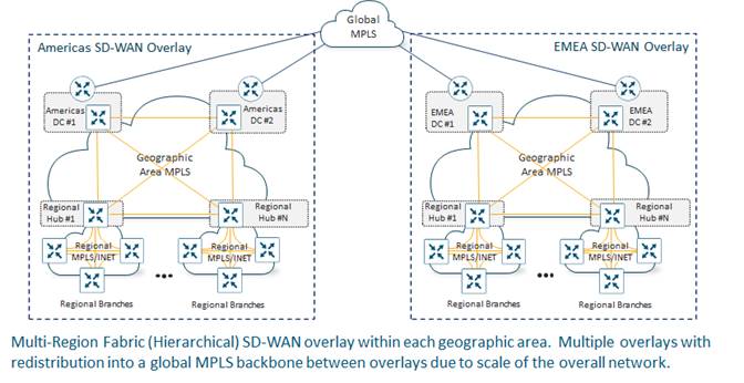
A multi-region fabric (hierarchical) SD-WAN design can result in reduced complexity, in terms of the centralized control policy, needed to create a hub-and-spoke topology. However, it would also require Bank of the Earth to re-architect their network to utilize some of the Large / Regional Branch Sites as SD-WAN Regional Hub Sites.
By deploying multiple Regional Hub Sites, the number of SD-WAN devices per regional fabric is smaller, and therefore the number of SD-WAN tunnels required within each regional full-mesh of branch sites would also be smaller. This would allow Bank of the Earth to utilize SD-WAN routers with lower price-points within the branch sites. However, this design would also require significant work in re-distributing circuits and circuit bandwidth from existing Data Center Sites to Regional Hub Sites to accommodate the design. The expanded role of the Large / Regional Branch Sites functioning as SD-WAN Regional Hub Sites would also require Bank of the Earth to re-evaluate their support model, which is based primarily upon having the necessary staff, physical space for equipment, uninterruptable power systems (UPS), air conditioning, etc., within their Data Center Sites today. Therefore, Bank of the Earth decided to table multi-region fabric (hierarchical) SD-WAN design initially and will consider it as a possible future design.
Network Topology Summary and Decision
Bank of the Earth concluded that the fabric data plane topology (and therefore, all the Service VPNs) within each SD-WAN overlay will be hub-and-spoke, based upon the following:
● The data flow patterns within their legacy MPLS-based network match a hub-and-spoke network topology. Bank of the Earth did not see any upcoming changes to the data flow pattern with or without SD-WAN.
● A hub-and-spoke network topology decreases the number of tunnels required at each of the branch sites. This allowed Bank of the Earth to deploy platforms that support fewer SD-WAN tunnels, which also fit within their price point, at the branch locations. It is only the head-end hub routers that needed to be scaled in terms of throughput and tunnel capacity.
● Bank of the Earth was satisfied that scalability of the data throughput at the head-end (in a hub-and-spoke topology) could be accomplished through horizontal scaling – by deploying multiple Catalyst router platforms at the head-end data center locations. This is discussed in the Data Center Design section of this document.
● Bank of the earth was satisfied that scalability of the tunnel count supported at the head-end (in a hub-and-spoke topology) could be accomplished through multiple Catalyst router platforms with the use of TLOC color restriction and Tunnel Groups. This is also discussed in the Data Center Design section of this document.
Bank of the Earth also recognized the following complications to the choice of a hub-and-spoke fabric data plane topology:
● Spoke-to-spoke (branch-to-branch) traffic must hairpin through the hub (head-end) routers. For voice and/or video applications, this could increase end-to-end latency, lowering the overall quality of experience (QoE) of the voice call. Bank of the Earth plans to evaluate the use of Dynamic on-Demand tunnels or a multi-region fabric SD-WAN design (also known as a hierarchical SD-WAN design) at a future point, as a possible means of mitigating this potential issue.
● A hub-and-spoke network topology introduces more complexity in terms of the centralized control policy needed to create the hub-and-spoke topology itself, particularly if TLOC rewrites are needed. The more complexity could result in larger centralized control policy, which could take longer to deploy and/or make changes within a production network. Bank of the Earth plans to evaluate a multi-region fabric (hierarchical) SD-WAN design at a future point, as a means of mitigating this potential issue as well.
After completing the migration from their legacy MPLS-based network design to SD-WAN, Bank of the Earth made the business decision to implement segmentation across their network for increased security. Up to four separate Service VPNs may be deployed within branch and data center sites. Strict separation of traffic between Service VPNs is both required and maintained by Bank of the Earth.
These Service VPNs consist of the following:
● Service VPN 10 (Employee VPN) – Used for internal business applications
● Service VPN 20 (ATM VPN) – Used for ATMs and other devices accessing internal financial applications
● Service VPN 30 (Monitoring VPN) – Used for logging information (syslog and/or SNMP traps) and in-band management
● Service VPN 40 (Guest VPN) – Used primarily for guest Wi-Fi access to the customer-facing Bank of the Earth web applications reachable via the Internet
Bank of the Earth provides additional customer services which are accessed primarily through public-facing web applications. These applications are currently hosted within Bank of the Earth’s on-prem data centers but may transition to cloud-hosted data centers at some point in the future. A portal, where customers are allowed to opt-in to use the guest Wi-Fi services at a branch site provides additional opportunities for Bank of the Earth to reach their customers with more personalized service, as well as providing a means for customers to access these services.
Medium-Sized and Large / Regional Branch Sites require all four Service VPNs. Small Branch Sites require Service VPN 20 (ATM VPN) and Service VPN 30 (Monitoring VPN). If a customer-facing representative is located at the Small Branch Site – meaning that the site offers more than just access to ATM machines – the site may also require Service VPN 10 (Employee VPN) and Service VPN 40 (Guest VPN). Bank of the Earth has made the business decision to extend Service VPN 40 (Guest VPN) to small branch offices where it is cost effective to provision and maintain guest Wi-Fi access in such small locations. Where it is not cost effective, customers can still access customer-facing web applications either through LTE/5G Internet access directly from the customer’s mobile device or guest Wi-Fi networks provided by the mall operator or retail store in which the small branch is located.
Bank of the Earth has decided upon an eight-digit Site ID numbering scheme for their branch and data center sites within each SD-WAN overlay.
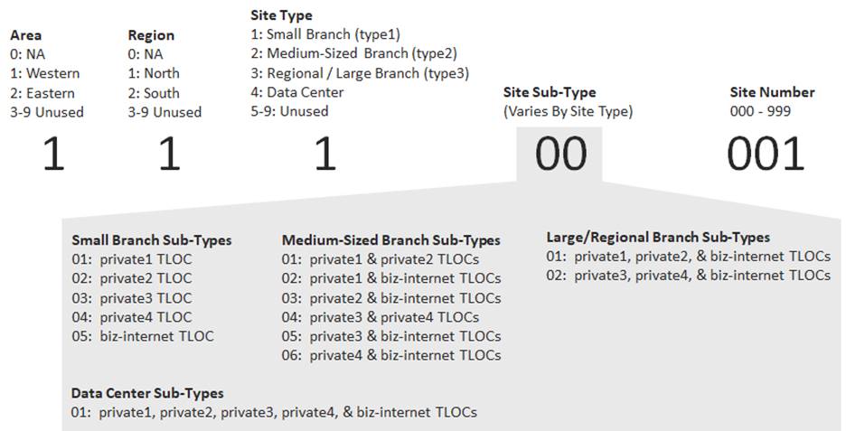
The site ID numbering scheme takes into consideration the following:
● The geographic area (west or east) within the overlay. As discussed in the Bank of the Earth Company Background and Legacy Network section, Bank of the Earth has grown largely through acquisitions and mergers. After consolidation, Bank of the Earth has two remaining data centers – DC#1 and DC#2 – within each overlay. DC#1 primarily services the branch locations in the western side of each overlay, and DC#2 primarily services the branch locations on the eastern side of each overlay.
● The geographic region (north or south) within each geographic area. As discussed in the Bank of the Earth Company Background and Legacy Network section, regional MPLS carriers primarily service branch sites within a geographic region, although each of the data centers – DC#1 (Western DC) and DC#2 (Eastern DC) – have connections to all regional MPLS carriers for redundancy purposes.
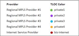
Regional MPLS Carrier #1, corresponding to TLOC color private1, primarily services northwestern branch sites
Regional MPLS Carrier #2, corresponding to TLOC color private2, primarily services southwestern branch sites
Regional MPLS Carrier #3, corresponding to TLOC color private3, primarily services northeastern branch sites
Regional MPLS Carrier #4, corresponding to TLOC color private4, primarily services southeastern branch sites
The centralized control policy applied to the branch sites also takes into consideration whether the branch is located within the northern or southern region of each geographic area – effectively splitting the branch sites within the overlay into four quadrants – northwest, southwest, northeast, and southeast. Note that since the data centers only reflect the geographic area (west or east) separate digits are used within the Site ID to identify geographic area (1 – West and 2 – East) and region (0 – Not Applicable, 1 – North, and 2 – South).
● The site type within the overlay. Bank of the Earth has identified four site types.
1 – Type 1 sites correspond to Small Branch Sites
2 – Type 2 sites correspond to Medium-Sized Branch Sites
3 – Type 3 sites correspond to Large / Regional Branch Sites
4 – Type 4 sites correspond to Data Center Sites
Each of the site types is discussed in the Branch SD-WAN Router Design section of this document.
● The site sub-type depends on the site type. Site sub-types reflect the different combinations of regional MPLS carriers, as well as any Internet connections, that each branch or data center SD-WAN router supports.
● The site number reflects the specific instance of the branch or data center site.
Bank of the Earth has implemented this Site ID numbering scheme to give them flexibility when configuring centralized control policy, with the ability to add and/or remove geographic areas, regions, site types, site sub-types, and site numbers. For example, the centralized control policy deployed within each overlay distinguishes between data center and branch sites. Furthermore, the centralized control policy applied to the branch sites can also take into consideration whether the branch is located on the western or eastern side of the overlay.
Bank of the Earth has identified the following SD-WAN branch prototypes, based upon the size of the branch.
Small Branch (Type 1) Sites
Bank of the Earth has defined two Small Branch (Type 1) prototypes as follows:
● Small Branch Type 1a – Single router, single regional MPLS WAN circuit
● Small Branch Type 1b – Single router, single Internet circuit
Small Branch Type 1a Sites
Small Branch Type 1a sites consist of a single SD-WAN router with a single MPLS circuit.
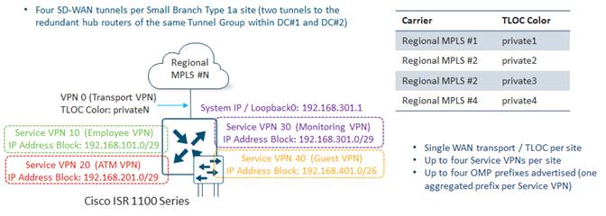
Because there is only a single MPLS WAN circuit, there is a single WAN transport (VPN 0) tunnel interface / TLOC per Small Branch Type 1a site. The TLOC color privateN (where N is from 1 to 4) matches one of the four regional MPLS carriers within the overlay, as shown in the figure above. Color restriction is configured such that SD-WAN tunnels only form to the WAN transport tunnel interfaces of the Data Center head-end routers connected to the same regional MPLS carrier.
The WAN transport (VPN 0) tunnel interface of each Small Branch Type 1a router is also configured to be part of either Tunnel Group 1 or 2, to balance the SD-WAN tunnels from the Small Branch sites across the head-end routers within the two Data Center Sites within each overlay. As a result of this configuration, a total of four SD-WAN tunnels are initiated from each Small Branch Type 1a Site.
Each Small Branch Type 1a Site supports up to four Service VPNs – VPNs 10, 20, 30, and 40. Service VPNs 10 (Employee VPN) and 40 (Guest VPN), are only needed for Small Branch Type 1a sites when they include a small, secured kiosk – such as a bank branch located within a larger store or shopping mall. Within the small, secured kiosk locations, one or two Ethernet ports can be made available to connect a PC / laptop, where a branch employee can assist customers. Service VPN 20 (ATM VPN) is used for Automated Teller Machine (ATM) connections. Service VPN 30 (Monitoring VPN) is used for the Loopback0 interface which is configured to be the source of logging information (Syslog) as well as SNMP traps.
Bank of the Earth has selected the Cisco ISR 1100 Series platform for Small Branch Type 1a Sites. This platform provides 4 Gigabit Ethernet switch ports. Small Branch Type 1a sites can support up to four ATMs, depending upon whether a port is needed for a branch employee PC / laptop.
IP addressing for each Small Branch Type 1a site has been carefully selected so that only a single aggregate prefix is advertised within OMP for each of the Service VPNs. The IP addressing shown in the figure above provides an example of how the addressing can be selected such that aggregate prefixes can be advertised for each Service VPN. Hence for each Small Branch Type 1a site, up to four OMP prefixes are advertised.
Small Branch Type 1b Sites
Small Branch Type 1b sites consist of a single SD-WAN router with a single Internet circuit.
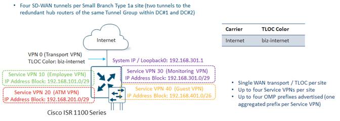
The only difference between Branch Prototype 1a and Branch Prototype 1b is the TLOC Color. Branch Prototype 1b is configured with a TLOC-color of biz-internet.
Small Branch Sites Summary
The following table summarizes the TLOCs, DTLS/TLS control connections, OMP sessions, SD-WAN tunnels, and advertised OMP prefixes from the Small Branch Sites within each Bank of the Earth overlay.
Table 2. Small Branch Sites Summary
| Parameter |
Per Overlay |
| Sites |
2,500 |
| TLOCs per Site |
1 |
| SD-WAN Controller DTLS / TLS Control Connections per Site |
2 |
| Total SD-WAN Controller DTLS / TLS Control Connections |
5,000 |
| OMP Sessions per Site |
2 |
| Total OMP Sessions |
5,000 |
| SD-WAN Tunnels per Site |
4 |
| Total SD-WAN Tunnels From All Small Branch Sites |
10,000 |
| OMP Prefixes Advertised per TLOC |
Up to 4 |
| OMP Prefixes Advertised per Site (Single TLOC) |
Up to 4 |
| Total OMP Prefixes Advertised From All Branch Sites |
Up to 10,000 |
Medium-Sized Branch (Type2) Sites
Bank of the Earth has defined two Medium-Sized Branch (Type 2) prototypes as follows:
● Medium-Sized Branch Type 2a – Single router with two regional MPLS WAN circuits
● Medium-Sized Branch Type 2b – Single router with one regional MPLS circuit and one Internet circuit
Medium-Sized Branch Type 2a Sites
Medium-Sized Branch Type 2a Sites consist of a single SD-WAN router with two MPLS circuits – each connected to one of the four regional MPLS carriers within each geographic area. Due to the geographic nature of the regional MPLS carriers, Medium-Sized Branch Type 2a Sites are connected to regional MPLS providers #1 and #2, or to regional MPLS providers #3 and #4. Those are the only two combinations of regional MPLS providers connected to Medium-Sized Branch (Type 2a) Sites.
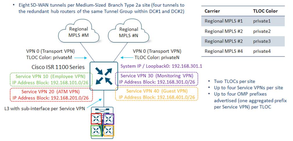
Because there are two MPLS WAN circuits, there are two WAN transport (VPN 0) tunnel interfaces / TLOCs per Medium-Sized Branch Type 2a site. The TLOC colors of each of the Medium-Sized Branch router WAN transport (VPN 0) tunnel interfaces matches one of the regional MPLS providers, as shown in the figure above. TLOC color restriction is configured such that SD-WAN tunnels only form to the WAN transport tunnel interfaces of the data center head-end routers connected to the same regional MPLS carrier.
Both WAN transport (VPN 0) tunnel interfaces of each Medium-Sized Branch Type 2a router are also configured to be part of either Tunnel Group 1 or 2, to balance the SD-WAN tunnels from the Medium-Sized Branch sites across the head-end routers within the two Data Center Sites within each overlay. As a result of this configuration, a total of eight SD-WAN tunnels are initiated from each Medium-Sized Branch Type 2a Site.
Each Medium-Sized Branch Type 2a Site supports up to four Service VPNs – VPNs 10, 20, 30, and 40. Service VPN 10 (Employee VPN), is for internal employee PCs / laptops. Service VPN 20 (ATM VPN) is used for Automated Teller Machine (ATM) connections. Service VPN 30 (Monitoring VPN) is used for the Loopback0 interface which is configured to be the source of logging information (Syslog) as well as SNMP traps. Service VPN 40 (Guest VPN) is used primarily for wireless guest Internet access which is currently backhauled to the Data Center sites before being sent to the Internet.
Bank of the Earth has selected the Cisco ISR 1100 Series platform for Medium-Sized Branch Type 2a Sites. To maintain segmentation between the Service VPNs, VRF-Lite is implemented on the Layer 3 distribution switch within the site. A single Layer 3 1 Gigabit Ethernet connection with four sub-interfaces (one for each Service VPN) connects the Medium-Sized Branch Type 2a SD-WAN router with the Layer 3 distribution switch. Layer 2 access switches may further connect to the Layer 3 distribution switch – with each Layer 2 access switch supporting one or more VLANs. A single VLAN or multiple VLANs can map back into the VRFs / Service VPNs within the Layer 3 distribution switch. This allows for either a single IP subnet or multiple IP subnets per Service VPN as needed.
IP addressing for each Medium-Sized Branch Type 2a Site has been carefully selected so that only a single aggregate prefix is advertised within OMP for each of the Service VPNs. The IP addressing shown in the figure above provides an example of how the addressing can be selected such that aggregate prefixes can be advertised for each Service VPN. When multiple subnets are needed within a Service VPN, the IP addressing is carefully chosen such that a single aggregated prefix can be sent from the site for that Service VPN. Hence for each Medium-Sized Branch Type 2a Site, up to four OMP prefixes are advertised.
Medium-Sized Branch Type 2b Sites
Medium-Sized Branch Type 2b Sites consist of a single SD-WAN router with one regional MPLS circuit and one Internet circuit.
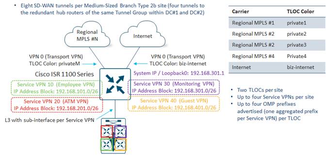
The only difference between Medium-Sized Branch Type 2a and Type 2b Sites is the TLOC-color of the second WAN transport. Medium-Sized Branch Type 2b SD-WAN routers are configured with a TLOC-color of biz-internet for the Internet-facing interface.
Medium-Sized Branch Sites Summary
The following table summarizes the TLOCs, DTLS / TLS control connections, OMP sessions, SD-WAN tunnels, and advertised OMP prefixes from the Medium-Sized Branch Sites within each overlay.
Table 3. Medium-Sized Branch Sites Summary
| Parameter |
Per Overlay |
| Sites |
2,300 |
| TLOCs per Site |
2 |
| SD-WAN Controller DTLS / TLS Control Connections per Site |
4 |
| Total SD-WAN Controller DTLS / TLS Control Connections |
9,200 |
| OMP Sessions per Site |
2 |
| Total OMP Sessions |
4,600 |
| SD-WAN Tunnels per Site |
8 |
| Total SD-WAN Tunnels From All Medium-Sized Branch Sites |
18,400 |
| OMP Prefixes Advertised per TLOC |
Up to 4 |
| OMP Prefixes Advertised per Site (2 TLOCs) |
Up to 8 |
| Total OMP Prefixes Advertised From All Medium-Sized Branch Sites |
Up to 18,400 |
Large / Regional Branch (Type3) Sites
Bank of the Earth has defined a single Large / Regional Branch (Type 3) prototype as follows:
● Large / Regional Branch Type 3 – Dual routers, each with dual regional MPLS WAN circuits (one via TLOC-Extension) and one Internet circuit
Large / Regional Branch Type 3 Sites
Large / Regional Branch Type 3 sites consist of two SD-WAN routers. Each SD-WAN router has one direct connection to one of the four regional MPLS service carriers within each geographic area. However, each SD-WAN router connects to a different regional MPLS provider for redundancy purposes. Each SD-WAN router also has a second connection to the opposite MPLS provider through a TLOC-Extension interface on the opposite router. Due to the geographic nature of the regional MPLS carriers, Large / Regional Branch Type 3 sites are connected to regional MPLS providers #1 and #2, or to regional MPLS providers #3 and #4. Those are the only two combinations of regional MPLS providers connected to Large / Regional Branch (Type 3) Sites. Finally, each Large / Regional Branch SD-WAN router has a direct connection to an Internet Service Provider (ISP) as well. The Internet connection provides a further level of high availability, as well as additional bandwidth to the branch. It may also provide a path for Direct Internet Access (DIA) for possibly guest Wi-Fi access or Software-as-a-Service (SaaS) application access, at some point in the future. Bank of the Earth has made the business decision that TLOC-Extension is not required for the Internet connection to reduce the number of SD-WAN tunnels at each Large / Regional Branch Type 3 Site.
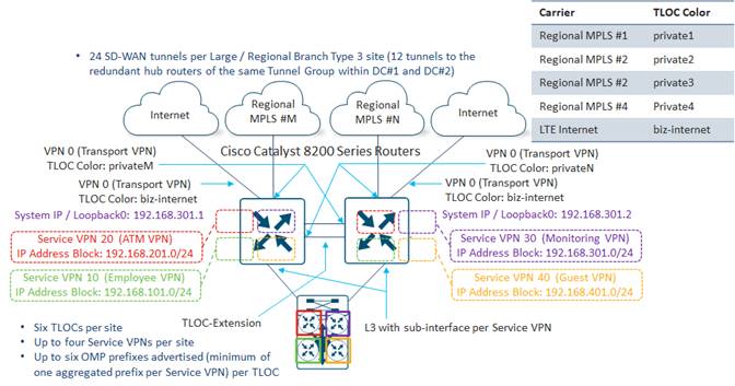
Each Large / Regional Branch Type 3 Site has a total of 6 WAN transport (VPN 0) tunnel interfaces / TLOCs. The TLOC colors of each of the Large / Regional Branch router MPLS tunnel interfaces match one of the regional MPLS providers, as shown in the figure above. The Internet TLOC color is biz-internet. TLOC color restriction is configured such that SD-WAN tunnels only form to the WAN transport tunnel interfaces of the data center head-end routers connected to the same regional MPLS carrier and/or the Internet connection.
The tunnel interfaces of each Large / Regional Branch Type 3 SD-WAN router are also configured to be part of either Tunnel Group 1 or 2, to balance the SD-WAN tunnels from the Large / Regional Branch Sites across the head-end routers within the two Data Center Sites within each overlay. As a result of this configuration, a total (from both SD-WAN routers) of 24 SD-WAN tunnels are initiated from each Large / Regional Branch Type 3 Site.
Each Large / Regional Branch Type 3 site supports up to four Service VPNs – VPN 10, 20, 30, and 40. Service VPN 10 (Employee VPN), is for employee PCs / laptops. Service VPN 20 (ATM VPN) is used for Automated Teller Machine (ATM) connections. Service VPN 30 (Monitoring VPN) is used for the Loopback0 interface which is configured to be the source of logging information (Syslog) as well as SNMP traps. Service VPN 40 (Guest VPN) is used primarily for wireless guest Internet access which is currently backhauled to the Data Center Sites before being sent to the Internet.
Bank of the Earth has selected the Cisco Catalyst 8200 Series platform for Large / Regional Branch Type 3 Sites. To maintain segmentation between the Service VPNs, VRF-Lite is implemented on the Layer 3 distribution switch within the site. A single Layer 3 10 Gigabit Ethernet connection with four sub-interfaces (one for each Service VPN) connects each Large / Regional Branch Type 3 SD-WAN router with the Layer 3 distribution switch. Layer 2 access switches may connect to the Layer 3 distribution switch, with each Layer 2 access switch supporting one or more VLANs. A single VLAN or multiple VLANs can map back into the VRFs / Service VPNs within the Layer 3 distribution switch. This allows for either a single IP subnet or multiple IP subnets per Service VPN as needed.
IP addressing for each Large / Regional Branch Type 3 site has been carefully selected so that ideally only a single aggregate prefix is advertised within OMP for each of the Service VPNs. The IP addressing shown in the figure above provides an example of how the addressing can be selected such that aggregate prefixes can be advertised for each Service VPN. When multiple subnets are needed within a Service VPN, the IP addressing is carefully chosen such that a single aggregated prefix can be sent from the site for that Service VPN. However, with the larger number of devices which need to be supported at each Large / Regional Branch Type 3 Site, Bank of the Earth recognizes that in some situations additional IP addressing space needs to be allocated per branch. Hence for each Large / Regional Branch Type 3 Site, up to six OMP prefixes can be advertised.
Large / Regional Branch Sites Summary
The following table summarizes the TLOCs, DTLS / TLS control connections, OMP sessions, SD-WAN tunnels, and advertised OMP prefixes from the Large / Regional Branch Sites within each overlay.
Table 4. Large / Regional Branch Sites Summary
| Parameter |
Americas Overlay |
| Sites |
596 |
| TLOCs per Site |
6 |
| SD-WAN Controller DTLS / TLS Control Connections per Site |
12 |
| Total SD-WAN Controller DTLS / TLS Control Connections |
7,152 |
| OMP Sessions per Site |
4 |
| Total OMP Sessions |
2,384 |
| SD-WAN Tunnels per Site |
24 |
| Total SD-WAN Tunnels From All Large / Regional Branch Sites |
14,304 |
| OMP Prefixes Advertised per TLOC |
Up to 6 |
| OMP Prefixes Advertised per Site (6 TLOCs) |
Up to 36 |
| Total OMP Prefixes Advertised from All Large / Regional Branch Sites |
21,465 |
Common Branch Design Principles
Regardless of the branch prototype, Bank of the Earth has decided that all branch locations will adhere to the following design principles:
● Use of IP prefix aggregation
● Use of TLOC color restriction
● Use of Tunnel Groups
IP Prefix Aggregation
The following figure provides an example of how the IP addressing of a Medium-Sized Branch Site can be carefully selected and configured such that a single aggregated IP prefix can be advertised per Service VPN via OMP from the site.
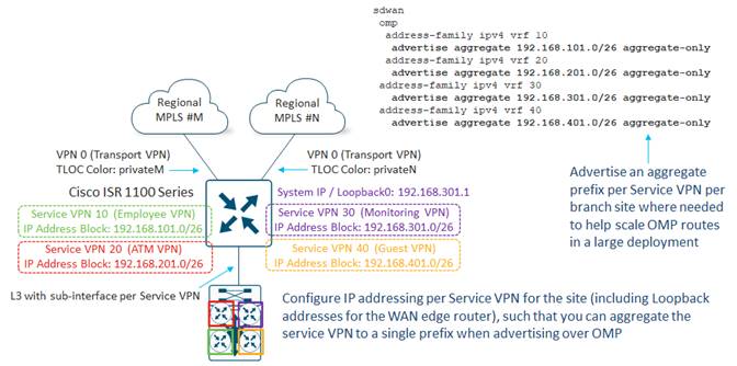
In the example above, the following IP address blocks have been allocated for the Medium-Sized Branch Site:
● 192.168.101.0/26 has been allocated for Service VPN 10 (Employee VPN) of the branch
● 192.168.201.0/26 has been allocated for Service VPN 20 (ATM VPN) of the branch
● 192.168.301.0/26 has been allocated for Service VPN 30 (Monitoring VPN) of the branch
● 192.168. 401.0/26 has been allocated for Service VPN 30 (Guest VPN) of the branch
Each Service VPN can consist of multiple IP subnets, and multiple VLANs connected via the downstream Layer 3 distribution switch and optionally additional Layer 2 access switches (not shown in the figure above).
By carefully choosing the IP address space of each Service VPN, the various subnets can be aggregated into a single prefix, corresponding to the IP address block shown in the figure above, for each Service VPN. Advertising an aggregate prefix per Service VPN – rather than multiple prefixes – per branch location, can help reduce the overall number of OMP routes within large deployments, helping to scale the deployment. This will be highlighted further within the OMP Routes section of this guide.
Also note that in the example above, a Loopback0 interface has been configured on the SD-WAN router within Service VPN 30 (Monitoring VPN). A Loopback interface is often used as a source for SNMP traps and logging information sent remotely. It also often serves as the in-band network management IP address used to reach the SD-WAN routers. Because of this, the Loopback IP address is often broadcast across OMP as well. By choosing the Loopback IP address to be within the aggregated prefix for the Service VPN, this again reduces the overall number of OMP routes within large deployments. Likewise, for downstream switches if a Loopback interface is used for monitoring and/or management purposes, the IP addressing should be selected from the IP address range of Service VPN 30 (Monitoring VPN) to preserve the ability to minimize the number of prefixes advertised by OMP per Service VPN, by sending aggregated prefixes.
TLOC Color Restriction and Tunnel Groups
The use of TLOC color restriction and tunnel groups will be discussed further in the Data Center Design section of this document.
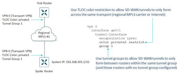
For the Bank of the Earth deployment, the same Tunnel Group is configured on all WAN (VPN 0) transports / TLOCs for a given branch site (Small Branch, Medium-Sized Branch, or Large / Regional Branch). In other words, the routers at a given branch site have all their tunnel interfaces configured for either Tunnel Group 1 or Tunnel Group 2. Half the branches within an overlay are configured to use Tunnel Group 1, and the other half are configured to use Tunnel Group 2. This ensures that half the branches within an overlay form SD-WAN tunnels to one pair of head-end routers in each Data Center Site, while the other half of the branches within that overlay form SD-WAN tunnels to the other pair of head-end routers in each Data Center Site. Although this reduces the number of SD-WAN tunnels required at both the branch and data center SD-WAN routers, the primary benefit is the reduction in the overall number of SD-WAN tunnels that need be supported at the head-end routers within each Data Center Site as the number of branch sites increases.
TLOC color restriction is also configured, such that SD-WAN tunnels are only formed across the same regional MPLS carrier or the Internet between the branch site SD-WAN router WAN transport tunnel interfaces and the data center hub SD-WAN router WAN transport tunnel interfaces. This also reduces the number of SD-WAN tunnels required at both the branch and data center SD-WAN routers.
When migrating from their legacy MPLS-based network to an SD-WAN network, Bank of the Earth made the business decision to maintain the design of redundant data centers within each geographic area. Each data center serves as a head-end location for implementing the hub-and-spoke SD-WAN data plane network topology discussed previously.
Data Center Head-End SD-WAN Router Design
Bank of the Earth realized early in the design process that they would need to use two methods of scaling the data plane of the head-end SD-WAN routers at the data center locations – vertical scaling and horizontal scaling. Both are necessary for the data centers to be able to handle the expected number of SD-WAN tunnels from all the branch sites, as well as the desired aggregated head-end throughput of up to 40 Gbps per data center.
Vertical scaling involves deploying head-end routers which can handle higher throughput and higher SD-WAN tunnel capacity. Throughput of SD-WAN routers is expressed in terms of millions of packets per second (Mpps) and gigabits per second (Gbps). This reflects the fact that throughput is constrained by how many packets per second the SD-WAN router can process. Hence the larger the packet size (for example 1,400 bytes), the higher the throughput in Gbps. Likewise, the lower the packet size (for example 64 bytes), the lower the throughput in Gbps. Actual customer networks do not have just one packet size. Therefore, for realistic throughput numbers, a mixture of packet sizes is used, based upon experience with existing customer networks. This is referred to as IMIX traffic. Hence, Bank of the Earth based their decision as to the platform choice for their data center head-end routers on throughput capacity of the platform with IMIX traffic.
Throughput is also based on the features enabled on the SD-WAN router platforms. Since Bank of the Earth has requirements for SAIE (formerly known as DPI) / statistics collection, they based their decision as to the platform of choice for their data center head-end routers on the combination of feature sets which include IPsec encapsulation on the SD-WAN overlay tunnels, Quality of Service (QoS), DPI, and Flexible NetFlow (FNF) collection and export.
After discussing platform choices with their Cisco account team, Bank of the Earth decided to implement Catalyst 8500 Series platforms as head-end SD-WAN routers within each of the data centers within each of the overlays.
Bank of the Earth made the business decision to maintain the existing four regional MPLS provider circuits, as well as the Internet circuit within each data center. Therefore, each SD-WAN head-end router has a WAN transport (VPN 0) tunnel interface connection to each of the four regional MPLS service providers, through their respective MPLS CE routers. In addition to this, each head-end SD-WAN router has a WAN transport (VPN 0) tunnel interface connection to the Internet via the Internet Edge firewall within the data center. Hence, each data center head-end SD-WAN router is configured with five TLOCs. The following figure shows the TLOC colors implemented at the head-end (and branch) routers for the Bank of the Earth SD-WAN network.
Use of TLOC Color Restriction
When branch and head-end SD-WAN routers support multiple WAN transport (VPN 0) tunnel interfaces / TLOCs, the number of SD-WAN tunnels between endpoints typically increases. The number of SD-WAN tunnels depends upon whether the customer has chosen to implement TLOC color restriction or not. TLOC color restriction prevents the formation of SD-WAN tunnels between TLOCs of different colors, as shown in the figure below.
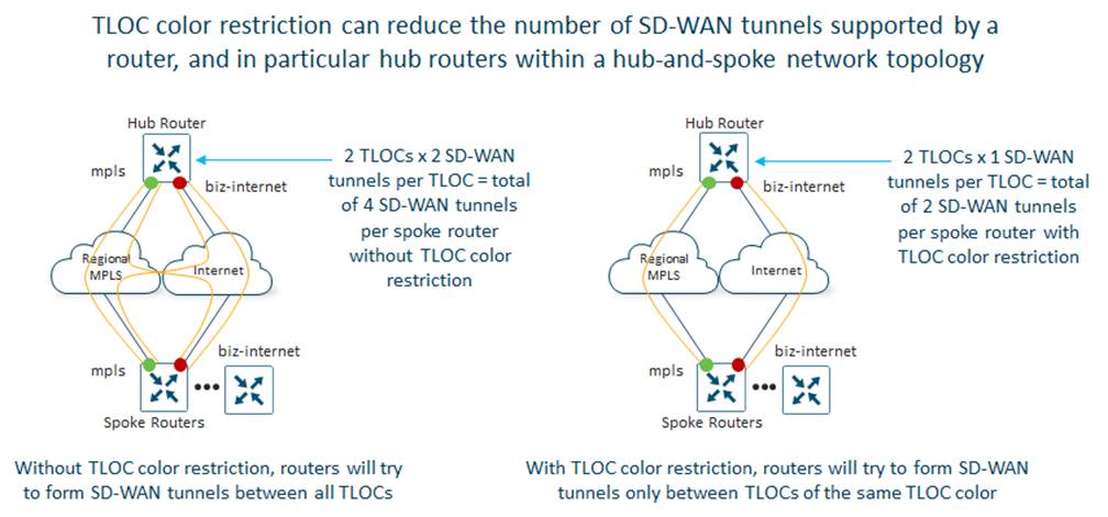
The use of TLOC color restriction can significantly reduce the number of SD-WAN tunnels needed at the head-end routers in a hub-and-spoke network topology. Because of this, Bank of the Earth decided to implement color restriction on each of the regional MPLS TLOCs (private1 through private4) and the Internet TLOC (biz-internet), within each SD-WAN overlay, to reduce the number of SD-WAN tunnels required on each head-end router within the data center sites.
| Technical Note |
| Since MPLS carriers typically utilize private (RFC 1918) IP addressing within their networks, and since Internet Service Providers (ISPs) may assign publicly routable (non-RFC 1918) IP addressing to devices requiring Internet access, it may not be possible in all scenarios to form SD-WAN tunnels between the two transports – regional MPLS and Internet – or even between two different regional MPLS carriers. |
Use of Tunnel Groups
Even with a hub-and-spoke fabric data plane topology and with TLOC color restriction, the data plane scale of the head-end Data Center Sites (hubs) is constrained both by the throughput as well as the maximum number of SD-WAN tunnels supported by the head-end SD-WAN routers. In a hub-and-spoke fabric data plane topology, when the number of branches in a single overlay becomes very large, even with TLOC color restriction the number of SD-WAN tunnels that need to be supported can exceed the capabilities of a single head-end router. Likewise, the throughput requirements of the hub site can exceed the capabilities of a single head-end router.
A pair of head-end SD-WAN routers can be used for resiliency and to load-balance traffic across the head-end routers, helping to alleviate the data throughput concerns. However, since the spoke (branch) routers still form SD-WAN tunnels to each hub router of the head-end router pair, redundant head-end routers do not alleviate the issue of head-end tunnel scale.
Bank of the Earth ran the calculations regarding the number of SD-WAN tunnels required at each data center head-end router for each overlay if all branch sites simply connected to a single pair of head-end routers as shown in the following figure.
The number of tunnels required is based on the branch prototype designs and the numbers of each branch type (Small, Medium-Sized, or Large / Regional) as discussed in the Branch SD-WAN Router Design section of this document. Also, as discussed within the Branch SD-WAN Router Design, each Bank of the Earth overlay is split into eastern and western geographic areas, with MPLS providers primarily servicing branches within their respective geographic areas.
As can be seen in the figure above, with a single pair of SD-WAN routers per data center, each data center head-end router would need to support over 10,000 SD-WAN tunnels. This exceeded the tunnel capabilities of the hardware platform that Bank of the Earth was targeting for their data center head-end SD-WAN routers.
One method to increase the total number of tunnels which can be supported at the head-end data center site – and therefore the total number of branch devices that can be supported in a hub-and-spoke fabric data plane topology – is to scale the data plane horizontally at the hub sites. Horizontal data plane scaling involves provisioning multiple SD-WAN routers (or multiple pairs of SD-WAN routers) at the head-end – and allowing only certain spoke (branch) routers to form SD-WAN tunnels to certain head-end (data center) routers. This can be done through Tunnel Groups, as shown in the following figure.
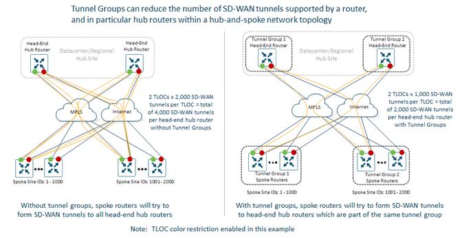
With Tunnel Groups, routers will only form SD-WAN tunnels between each other if the Tunnels Group number is the same, or if one or both sides is configured with no Tunnel Group (default Tunnel Group).
To scale out the ability of each data center site to support the required number of SD-WAN tunnels from all the branch sites within each overlay, Bank of the Earth re-designed the data centers to support two pairs of SD-WAN routers. Each pair of SD-WAN routers within each data center would be part of a different SD-WAN Tunnel Group, as shown in the following figure.
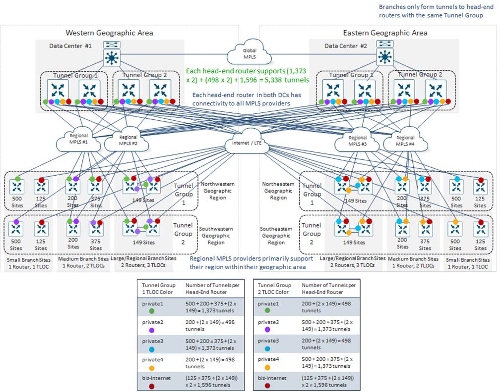
Since Bank of the Earth had already considered both the geographic area and region in the design of their Site ID numbering scheme, they could easily make use of this information to determine which branch sites should be part of Tunnel Group 1 and which branch sites should be part of Tunnel Group 2, to balance the SD-WAN tunnel count load between the sets of data center head-end SD-WAN routers.
Hence, Bank of the Earth used the Site ID numbering scheme information to configure all TLOCs within branch sites in the “north” regions (northwest and northeast) to be part of Tunnel Group 1 and all TLOCs within branch sites in the “south” regions (southwest and southeast) to be part of Tunnel Group 2. This effectively split the SD-WAN tunnel count load equally between the two sets of data center head-end SD-WAN routers.
As can be seen in the figure above, since the branch sites are now equally distributed across the sets of head-end SD-WAN routers, each set of routers must handle less than 5,500 SD-WAN tunnels. This is within the capabilities of the router platform which Bank of the Earth had targeted for the data center head-end hardware platform, based on feedback from their Cisco account team.
Note that this design also increases the throughput capacity of the overall data center site, since the traffic load from the branch sites is now spread across two sets of Catalyst head end routers. Note also that Bank of the Earth did not have to implement redundant sets of data center head-end SD-WAN routers. They could have implemented a single head-end SD-WAN router within each Tunnel Group (Tunnel Groups 1 and 2) at each data center, to scale the tunnel capacity at each data center. Even with the loss of a single data center within each SD-WAN overlay, branch sites still have connectivity to the other data center within their SD-WAN overlay – as well as connectivity to the data center and branch sites within the other SD-WAN overlay via the global MPLS network. This provides a first level of high-availability within the data plane of each SD-WAN overlay. However, a pair of head-end SD-WAN routers within each Tunnel Group in each data center provides a second level of high-availability – albeit at the cost of additional SD-WAN tunnels which need to be supported by each branch SD-WAN router, as well as additional OMP routes between the SD-WAN Controller instances and the SD-WAN routers within the overlay. This is due to the additional paths between the branch routers and the data centers due to the additional SD-WAN tunnels. The OMP Route Calculation section of this document discusses the calculation of the OMP routes and scalability considerations of the design.
Head-End SD-WAN Router Physical Connectivity
The following figure shows the design of the head-end SD-WAN routers within each data center.
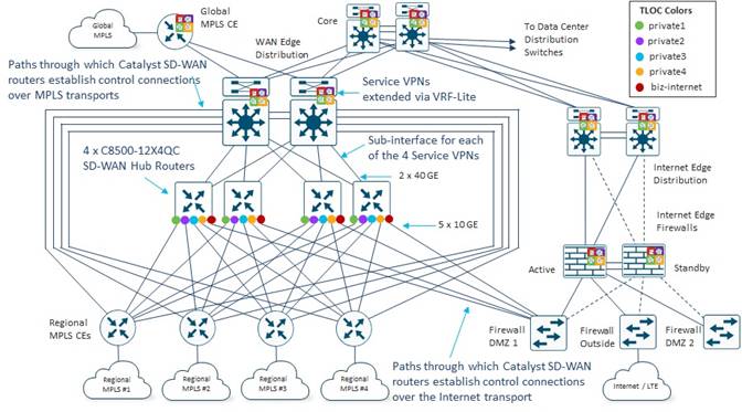
Each WAN transport of the head-end SD-WAN router is connected to a regional MPLS provider CE by way of a Layer 3 (routed) 10 Gbps interface. The IP addressing for the subnets for each of these connections must be advertised into their respective regional MPLS provider networks. It is necessary for the WAN transport (VPN 0) interfaces of the SD-WAN routers at the branch sites to have IP reachability with the WAN transport (VPN 0) interfaces of the data center SD-WAN head-end routers for SD-WAN tunnels to be formed between the branch and data center sites.
The LAN (Service VPN) side of each of the data center SD-WAN head-end routers connects to a pair of WAN Edge Distribution switches by way of two Layer 3 (routed) 40 Gbps interfaces. Each physical interface on the head-end SD-WAN routers is configured with four sub-interfaces – one for each Service VPN. Each Service VPN is extended to a separate virtual routing and forwarding instance (VRF) running on the WAN Edge Distribution switches. VRF-Lite configured on the WAN Edge Distribution switches extends the segmentation across the data center as well as across the global MPLS network. This ensures that segmentation is extended throughout Bank of the Earth’s network.
BGP routing is enabled – per Service VPN – between the data center head-end SD-WAN routers and the WAN Edge Distribution switches. As OMP routes from the branch sites are redistributed into BGP at each data center head-end SD-WAN router, the prefixes from the branch sites are tagged with a BGP community. Inbound BGP route filtering at the data center head-end SD-WAN routers is used to filter out branch routes that cross the global MPLS backbone between data centers and between overlays, to prevent unintentional loops from forming due to the redistribution of OMP routes to BGP and vice-versa.
The regional MPLS CEs were left in place with the Bank of the Earth design for a specific reason. It is necessary for the WAN transport (VPN 0) interfaces of the SD-WAN routers at the branch sites (and the data center head-end routers) to have IP reachability to the SD-WAN Validator, SD-WAN Manager, and SD-WAN Controllers. Specifically, each WAN transport (VPN 0) interface of an SD-WAN router that is connected to a regional MPLS provider needs to be able to initiate a DTLS control connection to the control (non-management) interface of the SD-WAN Validator controllers located within each of the data centers. Likewise, each WAN transport (VPN 0) interface of an SD-WAN router that is connected to a regional MPLS provider needs to be able to initiate a DTLS/TLS control connection to the control (non-management) interface of two SD-WAN Controller instances which may be in either data center within an overlay. As discussed in the SD-WAN Controller Design section, Bank of the Earth made the decision to leave the max-control-connections setting of all their SD-WAN routers at the default of 2. Finally, each SD-WAN router that is connected to a regional MPLS provider may need to initiate a DTLS/TLS control connection to the control (non-management and non-cluster-replication) interface of a SD-WAN Manager instance within the SD-WAN Manager cluster – regardless of whether it is the primary SD-WAN Manager cluster or the secondary / disaster recovery SD-WAN Manager cluster.
The IP addressing for SD-WAN control components must be advertised into their respective regional MPLS provider networks. Further, there must be a path by which the SD-WAN routers can reach the SD-WAN control components within the data centers. Bank of the Earth achieved this by leaving the existing regional MPLS CEs, with their connections into the WAN Edge Distribution switches in place. This also provided a path by which non-migrated MPLS branch sites could communicate with migrated SD-WAN branch sites during the migration phase of their SD-WAN rollout.
Likewise, each WAN transport (VPN 0) interface of an SD-WAN router that is connected to an Internet provider needs to be able to initiate a DTLS control connection to the control (non-management) interface of the SD-WAN Validator controllers located within each of the data centers. Likewise, each WAN transport (VPN 0) interface of an SD-WAN router that is connected to an Internet provider needs to be able to initiate a DTLS/TLS control connection to the control (non-management) interface of two SD-WAN Controller instances which may be in either data center within an overlay. Finally, each SD-WAN router that is connected to an Internet provider may need to initiate a DTLS/TLS control connection to the control (non-management and non-cluster-replication) interface of a SD-WAN Manager instance within the SD-WAN Manager cluster – regardless of whether it is the primary SD-WAN Manager cluster or the secondary / disaster recovery SD-WAN Manager cluster.
Hence, the IP addressing for the SD-WAN control components must also be advertised as publicly routable IP addresses on the Internet. Further, there must be a path by which the SD-WAN routers can reach the SD-WAN control components within the data centers via the Internet WAN transports. Bank of the Earth achieved this through the Internet Edge firewall. Note that the IP addressing of the SD-WAN control components is discussed in the SD-WAN Controller IP Addressing section of this document.
| Technical Note |
| Cisco SD-WAN has been rebranded to Cisco Catalyst SD-WAN. As part of this rebranding, the vManage name has been changed to SD-WAN Manager, the vSmart name has been changed to SD-WAN Controller, and the vBond name has been changed to SD-WAN Validator. Together, the vManage, vSmart, and vBond will be referred to as SD-WAN control components or the SD-WAN control complex in this document. |
Bank of the Earth made the decision to implement on-prem SD-WAN Validator, SD-WAN Controller, and SD-WAN Manager control components, as opposed to Cisco CloudOps or MSP cloud-hosted control components. This is primary due to their internal security operations guidance that all data (including management & control plane data) for the SD-WAN network remain on-site.
SD-WAN Manager Design
Bank of the Earth followed Cisco recommendations for SD-WAN control component sizing within each overlay, found at the following URL:
Within each overlay, for disaster recovery purposes a primary 6-node SD-WAN Manager cluster operating in single tenant mode was deployed in one data center, with a backup 6-node SD-WAN Manager cluster deployed in the other data center. The decision to implement 6-node SD-WAN Manager clusters is based on the total number of SD-WAN routers deployed in each overlay (greater than 4,000) and the requirement to enable SD-WAN Application Intelligence Engine (SAIE) statistics collection and processing on the SD-WAN Manager cluster itself, rather than offload it to the Cisco cloud-hosted vAnalytics service.
Each SD-WAN Manager instance is deployed with 32 vCPUs, 128 GB RAM, and 10 TB of storage (thick provisioning) on separate UCS servers, based on Cisco recommendations.
Although Bank of the Earth could have begun with a 3-node SD-WAN Manager cluster and scaled it out it to a 6-node cluster as the number of SD-WAN routers or daily amount of SAIE statistics collected exceeded the capabilities of a 3-node cluster; they decided to implement the required SD-WAN controller instances for the final end-state of each SD-WAN overlay. This was based on the business decision that minimizing the potential risk of disrupting the SD-WAN deployment during the migration from a 3-node cluster to a 6-node cluster outweighed the cost of purchasing and implementing additional hardware up front.
Likewise, Bank of the Earth could have started with less than 10 TB of disk storage allocated per SD-WAN Manager instance and expanded it as the amount of SAIE statistics collection increased over time. However, based on their expectations for total daily SAIE statistics collection when each SD-WAN overlay is fully deployed, they decided to allocate the full 10 TB of disk space up front on each UCS server.
Finally, administrator triggered failover between the primary and backup SD-WAN Manager clusters was implemented, since failover using an arbitrator is no longer supported by Cisco. Database synchronization between the primary and backup SD-WAN Manager clusters occurs over the DCI link between the primary and secondary data centers within each overlay.
When designing a large SD-WAN deployment it is generally recommended to separate SD-WAN Controller instances into different Controller Groups, and then use the system-level controller-group-list and tunnel-interface level exclude-controller-group-list commands on the SD-WAN routers to control which SD-WAN routers form DTLS/TLS control connections and OMP sessions to which SD-WAN Controller instances. This is referred to as SD-WAN Controller Affinity.
For the SD-WAN Controller design for Bank of the Earth’s overlays, a total of six SD-WAN Controller Groups are configured with two SD-WAN Controller instances in each Controller Group. Controller Groups 1 – 3 are configured in Data Center #1, and Controller Groups 4 – 6 are configured in Data Center #2.
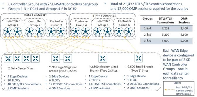
Each SD-WAN router is configured to be a member of two SD-WAN Controller Groups (Groups 1 and 4, Groups 2 and 5, or Groups 3 and 6) – with one Controller Group in each data center.
Small Branch Sites
SD-WAN routers within Small Branch Sites are configured to be members of SD-WAN Controller Groups 3 and 6.
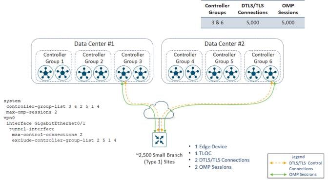
By default, each SD-WAN router will establish DTLS/TLS control connections to two SD-WAN Controller instances over each TLOC. This is controlled at the WAN transport tunnel-interface level by the max-control-connections command. Likewise, each SD-WAN router will establish OMP connections to two SD-WAN Controllers by default. This is controlled by the max-omp-sessions command. Bank of the Earth decided to leave these settings at the default values.
Each Small Branch Site has a single SD-WAN router which has a single WAN transport, and therefore a single TLOC. Therefore, each Small Branch Site initiates two DTLS/TLS control connections – one to a SD-WAN Controller in Controller Group 3 and the other to a SD-WAN Controller in Controller Group 6. One OMP session is initiated to the SD-WAN Controller in Controller Group 3 over the DTLS/TLS control connection, and one OMP session is initiated to the SD-WAN Controller in Controller Group 6 over the DTLS/TLS control connection – for a total of two OMP sessions per Small Branch Site.
Since there are approximately 2,500 Small Branch Sites within the Americas overlay, there are a total of 2 x 2,500 = 5,000 DTLS/TLS control connections established between all the Small Branch Sites and all the SD-WAN Controller instances in Controller Groups 3 and 6. Likewise, there are a total of 2 x 2,500 = 5,000 OMP sessions established between all the Small Branch Sites and all the SD-WAN Controller instances in Controller Groups 3 and 6. More specifically, 2,500 DTLS/TLS control connections and 2,500 OMP Sessions will be formed to the SD-WAN Controller instances in Controller Group 3 and 2,500 DTLS /TLS control connections and 2,500 OMP sessions will be formed to the SD-WAN Controller instances in Controller Group 6. A load-balancing algorithm within the SD-WAN router – based on the router’s System IP address – ensures approximately equal distribution of the DTLS/TLS control connections and OMP sessions across both SD-WAN Controller instances within each Controller Group.
Note that a single SD-WAN Controller instance in each of Controller Groups 3 and 6 is sufficient to handle the 2,500 DTLS/TLS control connections and 2,500 OMP sessions. However, Bank of the Earth wanted the SD-WAN Controller design to specifically address the scenario of a failure of one of the data centers within a given SD-WAN overlay. In the event of a failure of one of the data centers, all Small Branch Site SD-WAN routers will lose DTLS/TLS control connections and OMP sessions to the SD-WAN Controller instances in the Controller Group to which they belong within that data center.
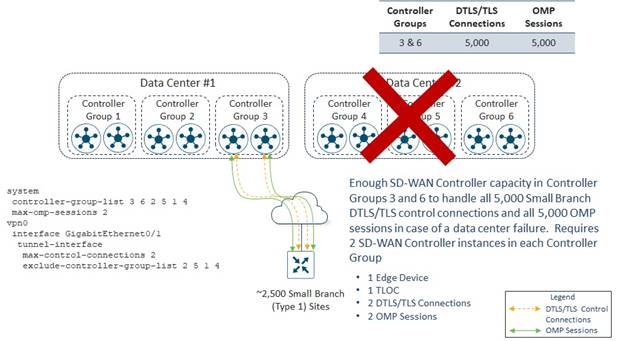
In the example above, if Data Center #2 fails, the Small Branch Site SD-WAN routers will lose DTLS/TLS control connections and OMP sessions to all SD-WAN Controller instances in Controller Group 6. Because the Small Branch Site SD-WAN routers are configured with the command max-omp-sessions 2 and the WAN transport interface is configured with the tunnel-interface level command max-control-connections 2, the SD-WAN router will be out of equilibrium – both regarding the number of DTLS/TLS control connections on the WAN transport tunnel-interface and the overall number of OMP sessions it has formed with SD-WAN Controllers.
The SD-WAN router will attempt to establish a second DTLS/TLS control connection over the WAN transport tunnel-interface. Since the WAN transport tunnel-interface has been configured to exclude Controller Groups 1, 2, 4, and 5, and since there is a second SD-WAN Controller instance within Controller Group 3, each small branch SD-WAN router will establish a second DTLS/TLS control connection to the second SD-WAN Controller instance within Controller Group 3. Over this second DTLS/TLS control connection, each small branch SD-WAN router will form a second OMP session. Note that an SD-WAN router will never form a second DTLS/TLS control connection or OMP session to the same SD-WAN Controller instance that it already has a DTLS/TLS control connection and OMP session.
At this point, each Small Branch Site SD-WAN router will have met the requirement for two DTLS/TLS control connections for the WAN transport tunnel-interface, as specified in the max-control-connections 2 command, and the requirement for two OMP sessions, as specified in max-omp-sessions 2 command. Note that since the TLOC of the Small Branch Site SD-WAN router is not connected to both of its “assigned” SD-WAN Controller instances, it is still considered “out of equilibrium”.
With two SD-WAN Controller instances in each of Controller Groups 3 and 6, if either Data Center #1 or #2 fails, sufficient SD-WAN Controller capacity is provisioned within each Controller Group to maintain the DTLS/TLS control connections and OMP sessions for the SD-WAN routers in the Small Branch Sites. Put another way, Small Branch Site SD-WAN routers have been compartmentalized to use only SD-WAN Controller instances within Controller Groups 3 and 6 during normal operations and in the event of the failure of one of the two data centers. This provides Bank of the Earth a deterministic way of ensuring there is sufficient SD-WAN Controller capacity for the Small Branch Sites, rather than trying to figure out how to spread individual the DTLS/TLS control connections and OMP sessions across the remaining Controller Groups without overrunning the capacity of any given SD-WAN Controller instance. This is particularly useful also, as Bank of the Earth adds or removes Small Branch Sites over time. Note that two SD-WAN Controller instances within each Controller Group already provides some excess capacity for Bank of the Earth to add additional Small Branch Sites. However, the downside of this design is that it does require the provisioning of double the number of SD-WAN Controller instances necessary for all DTLS/TLS control connections and OMP sessions from the Small Branch Sites.
Medium-Sized Branch Sites
Routers within the Medium-Sized Branch Sites are configured to be members of SD-WAN Controller Groups 2 and 5.
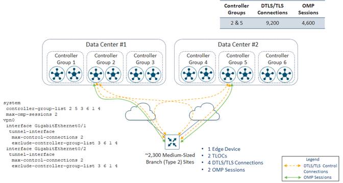
As with the Small Branch Site SD-WAN routers, Bank of the Earth decided to leave the max-control-connections and max-omp-sessions settings at their default values of 2.
Each Medium-Sized Branch Site has a single SD-WAN router which has a two WAN transports / TLOCs. Therefore, a total of four DTLS/TLS control connections and two OMP sessions are initiated from each Medium-Sized Branch Site. Each Medium-Sized Branch Site initiates two DTLS/TLS control connections – one to a SD-WAN Controller instance in Controller Group 2 and the other to a SD-WAN Controller instance in Controller Group 5 – from each of the two WAN transport tunnel-interfaces on the router. One OMP session is established to the SD-WAN Controller instance in Controller Group 2 over one of the DTLS/TLS control connections, and one OMP session is established to the SD-WAN Controller instance in Controller Group 5 over one of the DTLS/TLS control connections.
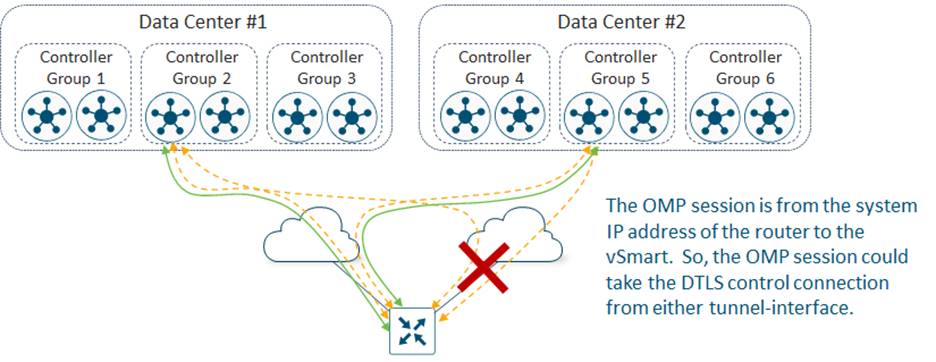
Since there are two DTLS/TLS control connections – one from each WAN transport tunnel-interface on the router – the OMP session may be established over either of these DTLS/TLS control connections on either WAN transport tunnel-interface. This is one of the benefits which Bank of the Earth recognized when they made the decision to leave the max-control-connections and max-omp-sessions settings at their default values for the Medium-Sized Branch Sites. If one of the WAN transport interfaces on a Medium-Sized Branch Site SD-WAN router goes down, the OMP session(s) to the SD-WAN Controller instance(s) which are riding over the DTLS/TLS control connections on that WAN transport tunnel-interface can simply switch over to the other DTLS/TLS control connection on the other WAN transport tunnel-interface. The SD-WAN Controller instance(s) will not see a loss of OMP peering, and therefore will not have to withdraw all routes (OMP, TLOC, multicast, service, etc.) available via the OMP peer.
Since there are approximately 2,300 Medium-Sized Branch Sites within the Americas overlay, there are a total of 4 x 2,300 = 9,200 DTLS/TLS control connections established between all the Medium-Sized Branch Sites and all the SD-WAN Controller instances in Controller Groups 2 and 5. Likewise, there are a total of 2 x 2,300 = 4,600 OMP sessions established between all the Medium-Sized Branch Sites and all the SD-WAN Controller instances in Controller Groups 2 and 5. More specifically, 4,600 DTLS/TLS control connections and 2,300 OMP Sessions will be formed to the SD-WAN Controller instances in Controller Group 2 and 4,600 DTLS /TLS control connections and 2,300 OMP sessions will be formed to the SD-WAN Controller instances in Controller Group 5. A load-balancing algorithm within the SD-WAN router – based on the router’s System IP address – ensures approximately equal distribution of the DTLS/TLS control connections and OMP sessions across both SD-WAN Controller instances within each Controller Group.
As with the small branch SD-WAN Controller design, a single SD-WAN Controller in each of Controller Groups 2 and 5 is sufficient to handle 4,600 DTLS/TLS control connections and 2,300 OMP sessions. However, Bank of the Earth wanted the SD-WAN Controller design to specifically address the scenario of a failure of one of the data centers within a given SD-WAN overlay. In the event of a failure of one of the data centers, all Medium-Sized Branch Site SD-WAN routers will lose DTLS/TLS control connections and OMP sessions to the SD-WAN Controller instances in the Controller Group to which they belong within that data center.
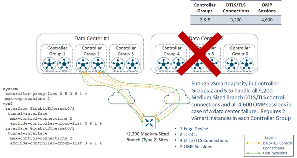
In the example above, if Data Center #2 fails, the Medium-Sized Branch Site SD-WAN routers will lose DTLS/TLS control connections and OMP sessions to all SD-WAN Controller instances in Controller Group 5. Because the Medium-Sized Branch Site SD-WAN routers are configured with the command max-omp-sessions 2 and each WAN transport is configured with the tunnel-interface level command max-control-connections 2, the SD-WAN routers will be out of equilibrium – both with respect to the number of DTLS/TLS control connections on each WAN transport tunnel-interface and the overall number of OMP sessions established with the SD-WAN Controllers.
The SD-WAN routers will attempt to establish a second DTLS/TLS control connection over each WAN transport tunnel-interface. Since the WAN transport tunnel-interfaces have been configured to exclude Controller Groups 3, 6, 1 and 4, and since there is a second SD-WAN Controller instance within Controller Group 2, each WAN transport tunnel-interface will establish a second DTLS/TLS control connection to the second SD-WAN Controller instance within Controller Group 2. Over one of the two DTLS/TLS control connections (because there are two WAN transport tunnel-interfaces), each Medium-Sized Branch Site SD-WAN router will form an OMP session with the second SD-WAN Controller instance. At this point, each Medium-Sized Branch Site SD-WAN router will have met the requirement for 2 DTLS/TLS control connections for each WAN transport tunnel-interface, as specified in the max-control-connections 2 command, and the requirement for 2 OMP sessions, as specified in max-omp-sessions 2 command. Note that since both TLOCs of the Medium-Sized Branch Site SD-WAN router are not connected to both of their “assigned” SD-WAN Controller instances, they are still considered “out of equilibrium”.
With two SD-WAN Controllers in each of Controller Groups 2 and 5, if either Data Center #1 or #2 fails, sufficient SD-WAN Controller capacity is provisioned for either Controller Group to maintain the SD-WAN routers in the Medium-Sized Branch Sites. As with the Small Branch Site routers, the Medium-Sized Branch Site SD-WAN routers have been compartmentalized to use only SD-WAN Controller instances within Controller Groups 2 and 5 during normal operations and in the event of the failure of one of the two data centers. This provides Bank of the Earth a deterministic way of ensuring there is sufficient SD-WAN Controller capacity for the Medium-Sized Branch Sites, rather than trying to figure out how to spread individual the DTLS/TLS control connections and OMP sessions across the remaining Controller Groups without overrunning the capacity of any given SD-WAN Controller. As with the Small Branch Sites, this is particularly useful as Bank of the Earth adds or removes Medium-Sized Branch Sites over time. Note that two SD-WAN Controller instances within each Controller Group already provides some excess capacity for Bank of the Earth to add additional Medium-Sized Branch Sites. However, as with the Small Branch Site SD-WAN Controller design, the downside of this design is that it requires provisioning double the number of SD-WAN Controller instances necessary for all DTLS/TLS control connections and OMP sessions from the Medium-Sized Branch Sites.
Data Center Sites and Large/Regional Branch Sites
SD-WAN routers within both the Data Center Sites and the Large/Regional Branch Sites are configured to be members of SD-WAN Controller Groups 1 and 4.
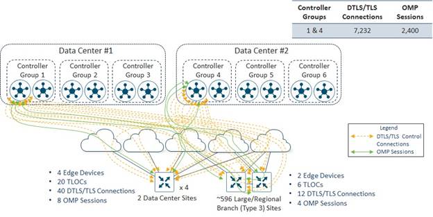
Data Center Sites
Each Data Center Site has four head-end / hub SD-WAN routers. The reason for four routers is for scalability (both throughput and tunnel capacity) and redundancy. This was discussed earlier within this document.
Each of the Data Center Site SD-WAN routers has five WAN transports / TLOCs (four regional MPLS carriers and one Internet connection). Maintaining consistency throughout their deployment, Bank of the Earth decided to leave the max-control-connections and max-omp-sessions settings at their default values of 2 for the Data Center Site SD-WAN routers, as shown in the configuration example below.
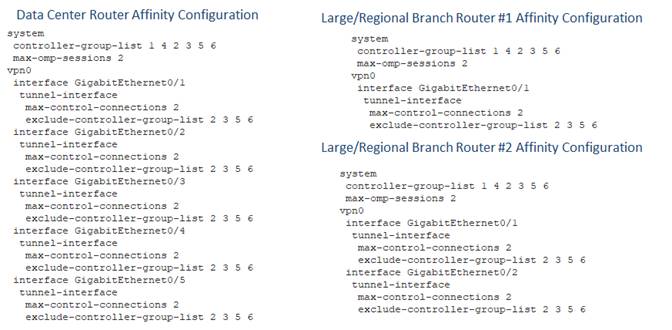
Each Data Center Site SD-WAN router initiates two DTLS/TLS control connections – one to a SD-WAN Controller instance in Controller Group 1 and the other to a SD-WAN Controller instance in Controller Group 4 – from each of the five WAN transport tunnel-interfaces. Since there are four head-end / hub SD-WAN routers within each Data Center Site, there are a total of 2 x 5 x 4 = 40 DTLS/TLS control connections per Data Center Site. One OMP session is established to the SD-WAN Controller instance in Controller Group 1 over any one of the five DTLS/TLS control connections, and one OMP session is established to the SD-WAN Controller instance in Controller Group 4 over any one of the five DTLS/TLS control connections – for a total of two OMP sessions per Data Center SD-WAN router. Again, since there are four Data Center SD-WAN routers, there are a total of 2 x 4 = 8 OMP sessions per Data Center Site.
Since there are two Data Center Sites within each overlay, there are a total of 2 x 40 = 80 DTLS/TLS control connections established between all the Data Center Site SD-WAN routers and all the SD-WAN Controller instances in Controller Groups 1 and 4. Likewise, there are a total of 2 x 8 = 16 OMP sessions established between all the Data Center Site SD-WAN routers and all the SD-WAN Controller instances in Controller Groups 1 and 4. More specifically, 40 DTLS/TLS control connections and 8 OMP Sessions will be formed to the SD-WAN Controller instances in Controller Group 1 and 40 DTLS /TLS control connections and 8 OMP sessions will be formed to the SD-WAN Controller instances in Controller Group 4. A load-balancing algorithm within the SD-WAN router – based on the router’s System IP address – ensures approximately equal distribution of the DTLS/TLS control connections and OMP sessions across both SD-WAN Controller instances within each Controller Group.
Large / Regional Branch Sites
Routers within the Large / Regional Branch Sites are also configured to be members of SD-WAN Controller Groups 1 and 4.
Large / Regional Branch Sites are configured with two SD-WAN routers. Each Large / Regional Branch Site SD-WAN router has a direct WAN transport interface connection to one MPLS regional provider, a direct WAN transport interface connection to an Internet Service Provider (ISP), and a WAN transport interface connection to a second regional MPLS provider via TLOC-Extension through the other SD-WAN router within the Large / Regional Branch Site.
Again, for consistency throughout their deployment, Bank of the Earth decided to leave the max-control-connections and max-omp-sessions settings at their default values of 2 for the Large / Regional Branch Site SD-WAN routers.
Each Large / Regional Branch Site initiates two DTLS/TLS control connections – one to a SD-WAN Controller instance in Controller Group 1 and the other to a SD-WAN Controller instance in Controller Group 4 – from each WAN transport tunnel-interface on each SD-WAN router. Therefore, a total of 2 x 3 x 2 = 12 DTLS/TLS control connections are initiated from each Large / Regional Branch Site. One OMP session is established to the SD-WAN Controller instance in Controller Group 1 over one of the DTLS/TLS control connections, and one OMP session is established to the SD-WAN Controller instance in Controller Group 4 over one of the DTLS/TLS control connections – for each SD-WAN router within each Large / Regional Branch Site. Because there are two SD-WAN routers within each Large / Regional Branch Site, there are a total of 2 x 2 = 4 OMP sessions per Large/Regional Branch Site.
Since there are approximately 596 Large / Regional Branch Sites within the Americas overlay, there are a total of 12 x 596 = 7,152 DTLS/TLS control connections established between all the Large / Regional Branch Site SD-WAN routers and all the SD-WAN Controller instances in Controller Groups 1 and 4. Likewise, there are a total of 4 x 596 = 2,384 OMP sessions established between all the Large / Regional Branch Site SD-WAN routers and all the SD-WAN Controller instances in Controller Groups 1 and 4. More specifically, 3,576 DTLS/TLS control connections and 1,192 OMP Sessions will be formed to the SD-WAN Controller instances in Controller Group 1 and 3,576 DTLS /TLS control connections and 1,192 OMP sessions will be formed to the SD-WAN Controller instances in Controller Group 4. A load-balancing algorithm within the SD-WAN router – based on the router’s System IP address – ensures approximately equal distribution of the DTLS/TLS control connections and OMP sessions across both SD-WAN Controller instances within each Controller Group.
Combined Data Center and Large / Regional Branch Sites
Summarizing the DTLS/TLS control connections and OMP sessions from both the Data Center and Large / Regional Branch Sites, there will be at total of 80 + 7,152 = 7,232 DTLS/TLS control connections established between all the Data Center and Large/Regional Branch Site SD-WAN routers and all the SD-WAN Controller instances in Controller Groups 1 and 4. Likewise there are a total of 16 + 2,384 = 2,400 OMP sessions established between all the Data Center and Large / Regional Branch Site SD-WAN routers and all the SD-WAN Controller instances in Controller Groups 1 and 4. More specifically 3,616 DTLS/TLS control connections and 1,200 OMP sessions will be formed to the SD-WAN Controller instances in Controller Group 1 and 3,616 DTLS/TLS control connections and 1,200 OMP sessions will be formed to the SD-WAN Controller instances in Controller Group 4. A load-balancing algorithm within the SD-WAN router – based on the router’s System IP address – ensures approximately equal distribution of the DTLS/TLS control connections and OMP sessions across both SD-WAN Controller instances within each Controller Group.
As with the Small and Medium-Sized Branch Site SD-WAN Controller designs, a single SD-WAN Controller in each of Controller Groups 1 and 4 is sufficient to handle 3,616 DTLS/TLS control connections and 1,200 OMP sessions. However, Bank of the Earth wanted the SD-WAN Controller design to specifically address the scenario of a failure of one of the Data Center Sites within a given SD-WAN overlay. In the event of a failure of one of the Data Center Sites, all Data Center and Large / Regional Branch Site SD-WAN routers will lose DTLS/TLS control connections and OMP sessions to the SD-WAN Controller instances in the Controller Group to which they belong within that Data Center.
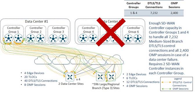
In the example above, if Data Center #2 fails, the Data Center and Large / Regional Branch Site SD-WAN routers will lose DTLS/TLS control connections and OMP sessions to all SD-WAN Controller instances in Controller Group 4. Because the Data Center and Large / Regional Branch Site SD-WAN routers are configured with the command max-omp-sessions 2 and each WAN transport is configured with the tunnel-interface level command max-control-connections 2, the SD-WAN routers will be out of equilibrium – both with respect to the number of DTLS/TLS control connections on each WAN transport tunnel-interface and the overall number of OMP sessions established with SD-WAN Controllers.
The SD-WAN routers will attempt to establish a second DTLS/TLS control connection over each WAN transport tunnel-interface. Since the WAN transport tunnel-interfaces have been configured to exclude Controller Groups 2, 3, 5, and 6, and since there is a second SD-WAN Controller instance within Controller Group 1, each WAN transport tunnel-interface will establish a second DTLS/TLS control connection to a SD-WAN Controller within Controller Group 1. Over one of the two DTLS/TLS control connections (because there may be multiple WAN transport tunnel-interfaces), each Data Center and Large / Regional Branch Site SD-WAN router will form a second OMP session.
At this point, each Data Center and Large / Regional Branch Site SD-WAN router will have met the requirement for 2 DTLS/TLS control connections for each WAN transport tunnel-interface, as specified in the max-control-connections 2 command, and the requirement for 2 OMP sessions, as specified in max-omp-sessions 2 command. Note that since all the TLOCs of each of the Large / Regional Branch and Data Center Site SD-WAN routers are not connected to both of their “assigned” SD-WAN Controller instances, they are all still considered “out of equilibrium”.
With two SD-WAN Controllers in each of Controller Groups 1 and 4, if either Data Center #1 or #2 fails, sufficient SD-WAN Controller capacity is provisioned for either Controller Group to maintain the SD-WAN routers in the Data Center and Large / Regional Branch Sites. As with the Small and Medium-Sized Branch Site SD-WAN routers, the Data Center and Large / Regional Branch Site SD-WAN routers have been compartmentalized to use only SD-WAN Controller instances within Controller Groups 1 and 4 during normal operations and in the event of the failure of one of the two Data Centers. This provides Bank of the Earth a deterministic way of ensuring there is sufficient SD-WAN Controller capacity for the Data Center and Large / Regional Branch Sites, rather than trying to figure out how to spread individual the DTLS/TLS control connections and OMP sessions across the remaining Controller Groups without overrunning the capacity of any given SD-WAN Controller instance. This is particularly useful also, as Bank of the Earth adds or removes Large / Regional Branch Sites over time. Note that two SD-WAN Controller instances within each Controller Group already provides some excess capacity for Bank of the Earth to add additional Large / Regional Branch Sites. However, as with the Small and Medium-Sized Branch Site SD-WAN Controller designs, the downside of this design is that it requires provisioning double the number of SD-WAN Controller instances necessary for all DTLS/TLS control connections and OMP sessions from the Data Center and Large / Regional Branch Sites.
SD-WAN Controller Design Summary
One downside to the overall SD-WAN Controller design presented in this section, is that under normal operations, there is no deterministic way to ensure that each SD-WAN router installs OMP routes or centralized data policy from the SD-WAN Controller within the Data Center to which the SD-WAN router is geographically closest. This may not be needed, since all SD-WAN Controller instance are fully meshed and exchange routes with each other. Likewise centralized data policy is downloaded from the SD-WAN Manager to each of the SD-WAN Controller instances, which then downloads it to the SD-WAN routers. However, in some scenarios, it may be desirable to ensure that head-end SD-WAN routers within Data Center #1 and branch SD-WAN routers geographically closest to Data Center #1 install routes and centralized policy from SD-WAN Controller instances located within Data Center #1, during normal operations. Likewise, it may be desirable to ensure that head-end SD-WAN routers within Data Center #2 and branch SD-WAN routers geographically closest to Data Center #2 install routes and centralized policy from SD-WAN Controller instances located within Data Center #2, during normal operations. Because of this, Bank of the Earth also looked at an alternative SD-WAN Controller design for each of its overlays, discussed in Appendix C.
| Technical Note |
| Note that the order of the SD-WAN Controller Group within the controller-group-list does not have any effect on the preference to which the SD-WAN router gives to OMP routes or centralized data policy received from the SD-WAN Controller instances. Instead, the OMP best-path algorithm, discussed in the following document is used: With SD-WAN Controller Affinity, its recommended to assign each SD-WAN Controller in an overlay to a controller group and include all the controller groups in the controller-group-list configuration of each router – if the desired behavior is to allow all SD-WAN routers to connect to any SD-WAN Controller instance as a last resort. |
For brevity, only the SD-WAN Validator design for a single overlay will be discussed within this guide. The same design principles apply to the SD-WAN Validator design for both overlays.
As discussed in the SD-WAN Controller Design section of this document, Bank of the Earth designed SD-WAN Controller Affinity such that during normal operations, all Data Center and Branch Site SD-WAN routers form DTLS/TLS control connections and OMP sessions to one SD-WAN Controller instance in Data Center #1 (Western Data Center) and one SD-WAN Controller instance in Data Center #2 (Eastern Data Center). As a result of this design decision, in the event of the failure of either Data Center, each WAN transport (VPN 0) tunnel interface / TLOC of every SD-WAN router within the overlay will be “out of equilibrium”.
The behavior of each TLOC of an SD-WAN router when it is out of equilibrium is to establish a persistent DTLS control connection with a SD-WAN Validator instance. Each TLOC of the SD-WAN router does this to determine if it should continue trying to connect to a failed SD-WAN Controller instance or whether it should connect to a different SD-WAN Controller instance, based on the following possible scenarios:
● If a SD-WAN Controller instance has been decommissioned or replaced with a new SD-WAN Controller instance by the network administrator, the SD-WAN Validators will know about this change through their DTLS control connections with the SD-WAN Manager cluster, and their DTLS control connections to each SD-WAN Controller instance. The SD-WAN Validators will generate a new list of SD-WAN Controller instances within the overlay. When each TLOC of the SD-WAN router establishes a DTLS control connection with a SD-WAN Validator, it will download the new / updated list of SD-WAN Controller instances. Based on this new list, each TLOC of an SD-WAN router will determine its new preferred SD-WAN Controller instances – taking into consideration the max-omp-sessions and controller-group-list configurations, and the tunnel-interface level max-control-connections and exclude-controller-group-list configurations on the SD-WAN router itself. Each TLOC of the SD-WAN router will establish DTLS/TLS control connections its new SD-WAN Controller instances. Over the new DTLS/TLS control connections established by the TLOCs, the SD-WAN router will then establish OMP sessions. Each TLOC of the SD-WAN router will drop the DTLS control connection to the SD-WAN Validator.
● If the SD-WAN Controller instance is unavailable to the TLOCs of the SD-WAN router, but still available to the SD-WAN Validators (meaning the SD-WAN Validators still have DTLS control connections to the SD-WAN Controller instance), then the list of SD-WAN Controller instances which each TLOC of the SD-WAN router downloads from the SD-WAN Validator will be equal to (the same as) the list of SD-WAN Controller instances within the TLOC of the SD-WAN router. In this situation, each TLOC of the SD-WAN router will establish DTLS/TLS control connections to another “non-assigned” SD-WAN Controller instance to satisfy its tunnel-interface level max-control-connections configuration. The SD-WAN router will establish an OMP session with the other “non-assigned” SD-WAN Controller instance over the new DTLS/TLS control connections established by the TLOCS, to satisfy its max-omp-sessions. However, each TLOC of the SD-WAN router will keep the original SD-WAN Controller as its “assigned” instance and will still be out of equilibrium. Each TLOC of the SD-WAN router will maintain the DTLS control connection to SD-WAN Validator. Each TLOC of the SD-WAN router will also periodically continue to try to establish DTLS/TLS control connections with the “assigned” SD-WAN Controller instance. When the “assigned” SD-WAN Controller instance comes back online, each TLOC of the SD-WAN router will establish DTLS/TLS control connections to it. Over the DTLS/TLS control connections established by the TLOCs, the SD-WAN router will then establish OMP sessions. Each TLOC of the SD-WAN router will be back in equilibrium and will drop the DTLS control connection to the SD-WAN Validator.
● If the SD-WAN Controller instance is unavailable to the TLOCs of the SD-WAN router and is also unavailable to the SD-WAN Validators (which would be the case in a data center failure), then the list of SD-WAN Controller instances which each TLOC of the SD-WAN router downloads from the SD-WAN Validator will be inferior to (less than) the list of SD-WAN Controller instances within the TLOC of the SD-WAN router. Again, in this situation, each TLOC of the SD-WAN router will establish DTLS/TLS control connections to another “non-assigned” SD-WAN Controller instance to satisfy its tunnel-interface level max-control-connections configuration. The SD-WAN router will establish an OMP session with the other “non-assigned” SD-WAN Controller instance over the new DTLS/TLS control connections established by the TLOCS, to satisfy its max-omp-sessions configuration. However, each TLOC of the SD-WAN router will keep the original SD-WAN Controller as its “assigned” instance and will still be out of equilibrium. Each TLOC of the SD-WAN router will maintain the DTLS control connection to SD-WAN Validator. Each TLOC of the SD-WAN router will also periodically continue to try to establish DTLS/TLS control connections with the “assigned” SD-WAN Controller instance. When the “assigned” SD-WAN Controller instance comes back online, each TLOC of the SD-WAN router will establish DTLS/TLS control connections to it. Over the DTLS/TLS control connections established by the TLOCs, the SD-WAN router will then establish OMP sessions. Each TLOC of the SD-WAN router will be back in equilibrium and will drop the DTLS control connection to the SD-WAN Validator.
Based upon the design of having each TLOC of all the SD-WAN routers within the overlay establish one DTLS/TLS control connection to a SD-WAN Controller instance in one data center (DC #1) and one DTLS/TLS control session to a SD-WAN Controller instance in the other data center (DC #2) – all TLOCs within all SD-WAN routers within the overlay will be out of equilibrium in the event of a data center failure.
Bank of the Earth specifically wanted to ensure that, in the event of a data center failure, the SD-WAN routers would always have one OMP session to each SD-WAN router which would be unaffected. Bank of the Earth could have designed their SD-WAN Controller Affinity such that half the SD-WAN routers in the overlay established two DTLS/TLS control connections over each TLOC (and two OMP sessions to the same two SD-WAN Controller instances over those DTLS/TLS control connections) to two SD-WAN Controller instances in the same data center (DC #1). The other half of the SD-WAN routers in the overlay would establish two DTLS/TLS control connections over each TLOC (and two OMP sessions to the same two SD-WAN Controller instances over those DTLS/TLS control connections) to two SD-WAN Controller instances in the other data center (DC #2). However, Bank of the Earth decided that having geographic redundancy of the control plane was more desirable from a design perspective – meaning that with the loss of a single data center all SD-WAN routers would maintain one OMP session with one SD-WAN Controller instance, rather than half the routers losing both/all OMP sessions with both / all SD-WAN Controller instances.
As a result of this design decision, Bank of the Earth needed to provision sufficient instances of the SD-WAN Validator within each data center such that all TLOCs of all SD-WAN routers will be able to simultaneously establish and maintain DTLS control connections to the SD-WAN Validators within the remaining data center. Each TLOC of each SD-WAN router will establish one DTLS control connection to a SD-WAN Validator instance.
To get an estimate of the total number of DTLS control connections required, Bank of the Earth determined the total number of TLOCs across all the SD-WAN routers (branch sites and data center sites) within the overlay. The Branch Site Design section of this guide discusses the total number of each branch site (Small, Medium-Sized, and Large/Regional) as well as the total number of TLOCs per branch site. The Data Center Head-End SD-WAN Router Design section of this guide discusses the total number of data center head-end routers and the number of TLOCs per head-end router across the two data center sites per overlay. The following table summarizes the total number of TLOCs across the overlay.
Table 5. Total Number of TLOCs Across Each Bank of the Earth Overlay
| Site Type |
Number of Sites |
Number of SD-WAN Routers per Site |
Number of TLOCs per SD-WAN Router |
Number of TLOCs per Site |
Total Number of TLOCs |
| Small Branch |
2,500 |
1 |
1 |
1 |
2,500 |
| Medium-Sized Branch |
2,300 |
1 |
2 |
2 |
4,600 |
| Large / Regional Branch |
596 |
2 |
3 |
6 |
3,576 |
| Data Center |
2 |
4 |
5 |
20 |
40 |
| TOTAL |
5,398 |
--- |
--- |
--- |
10,716 |
In a worst-case scenario of the failure of one of the data centers, Bank of the Earth would require sufficient SD-WAN Validators to support approximately 10,696 (10,716 – 20 TLOCs from the data center which is down) DTLS sessions within the remaining data center.
To support 10,696 DTLS sessions from either data center, after talking to their Cisco account team, Bank of the Earth determined that they would require three SD-WAN Validators instances per data center within each SD-WAN overlay as shown in the figure below.
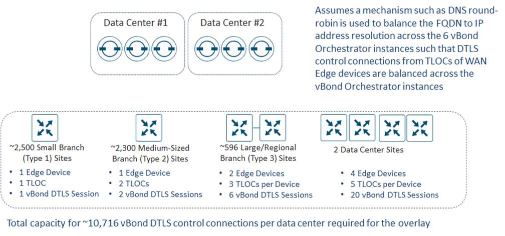
Bank of the Earth uses fully qualified domain names (FQDNs) for the SD-WAN Validator instances and relies on their DNS servers to round-robin the FQDN to IP address resolution to balance the DTLS control connections from the SD-WAN routers within each overlay to the six SD-WAN Validator instances. This is necessary to ensure that no single SD-WAN Validator instance is overrun with DTLS control connections.
SD-WAN Controller OMP Route Calculations
This section discusses the calculation of received routes and sent routes for each SD-WAN Controller for the Bank of the Earth design. The number of received routes determines the size of the RIB-in table of each SD-WAN Controller instance, while the number of sent routes determines the size of the RIB-out table of each SD-WAN Controller instance. The size of the RIB-in and RIB-out tables consumes memory on each SD-WAN Controller instance, which forms the primary constraint regarding the maximum OMP routes supported by each SD-WAN Controller instance. Hence, the information regarding how to calculate the number of routes received (RIB-in table size) and the number of routes sent (RIB-out table size) is necessary to ensure that each SD-WAN Controller within each of the overlays is within Cisco guidance.
For a detailed discussion of how routes received (RIB-in) and routes sent (RIB-out) are calculated within an SD-WAN deployment, please refer to Appendix E.
As discussed in the SD-WAN Controller Design section of this document, Bank of the Earth deployed a total of 12 SD-WAN Controller instances in six Controller Groups (2 SD-WAN Controller instances per Controller Group) across both data centers within each overlay, as shown in the following figure.
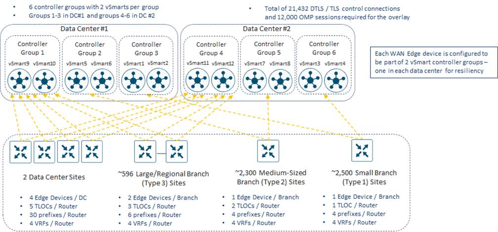
The figure above includes the following information relevant for the calculation of routes received and routes sent:
● The number of each site type (Small Branch, Medium-Sized Branch, Large / Regional Branch, or Data Center) which will form OMP sessions with specific SD-WAN Controller instances, as well as the number of SD-WAN routers implemented for each site type. Together, this provides the number of SD-WAN routers which form OMP sessions to specific SD-WAN Controller instances.
● The number of TLOCs per SD-WAN router
● The number of unicast IPv4 prefixes per site
Together, this information determines how many unicast IPv4 prefixes are sent from each SD-WAN router in the overlay to each of the SD-WAN Controller instances.
| Technical Note: |
| The figure above also indicates the number of Service VPNs / VRFs per router. The number of prefixes advertised through OMP from each SD-WAN router is more precisely equal to the number of prefixes per Service VPN multiplied by the number of Service VPNs. However, for calculating the number prefixes received by each SD-WAN Controller, only the total number of prefixes sent by the router, regardless of the Service VPN through which the route is visible is needed. |
| Technical Note: |
| This guide only includes discussion of IPv4 unicast OMP routes. It does not include any discussion of additional routes such as service routes (used for implementing service-chaining), IPv6 unicast routes, IPv4 multicast routes, etc. |
Routes Received (RIB-in) Calculations and Scale
The Bank of the Earth SD-WAN Controller design is based on the use of Controller Groups – otherwise known as Affinity. Different site types (Small Branch, Medium-Sized Branch, Large/Regional Branch, and Data Center) form DTLS/TLS and OMP sessions to different sets of SD-WAN Controller instances configured in different Controller Groups.
The routes received (RIB-in) calculation for each SD-WAN Controller instance consists of two components:
● Edge routes received from SD-WAN routers which have OMP-peering relationships with the specific SD-WAN Controller instance. This can be expressed with the following equation:
Edge received routes = Number of routers (hub or spoke) with OMP sessions
to the SD-WAN Controller x
Number of prefixes sent per router x
Number of TLOCs per router
● SD-WAN Controller received routes from the other SD-WAN Controller instances within the overlay which are reflected to the specific SD-WAN Controller instance. SD-WAN Controller instances only reflect routes to other SD-WAN Controller instances when the route is received from an SD-WAN router (Edge device). In other words, SD-WAN Controller instances only reflect routes received from SD-WAN routers which are OMP-peered to the given SD-WAN Controller. Hence, the received routes from other SD-WAN Controller instances is the sum of edge received routes from each of the other SD-WAN Controller instances within the overlay. This can be expressed with the following equation:
⅀ (Edge received routes from each of the other SD-WAN Controller instances in the overlay which are reflected to the SD-WAN Controller instance)
Small Branch RIB-in Calculations - Partial
As discussed in the Branch Design section of this guide, each Small Branch Site consists of a single router configured with a single TLOC, which can be MPLS-based (private1, private2, private3, or private4) or Internet-based (biz-internet). Each Small Branch Site supports up to four IPv4 prefixes advertised into OMP – one aggregated IP prefix for each Service VPN / VRF.
Small Branch Sites are configured for SD-WAN Controller Groups 3 & 6. Controller Group 3, located in Data Center #1, contains two instances – SD-WAN Controller 1 and SD-WAN Controller 2. Controller Group 6, located in Data Center #2, also contains two instances – SD-WAN Controller 3 and SD-WAN Controller 4.
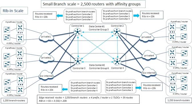
There are a total of 2,500 Small Branch Sites within each overlay. Half of the Small Branch Sites (1,250) are in the western side of the overlay, and therefore form DTLS/TLS control connections and OMP sessions to one SD-WAN Controller instance in Controller Group 3 and one SD-WAN Controller instance in Controller Group 6, in that order. The other half of the Small Branch Sites (1,250) are in the eastern side of the overlay, and therefore form DTLS/TLS control connections and OMP sessions to one SD-WAN Controller instance in Controller Group 6 and one SD-WAN Controller instance in Controller Group 3, in that order.
For simplicity of the RIB-in calculations, all 1,250 Small Branch Site routers in the western side of the overlay are shown with OMP sessions to SD-WAN Controller 1 in Data Center #1 and SD-WAN Controller 3 in Data Center #2, in the figure above. Likewise, all 1,250 Small Branch Site routers in the eastern side of the overlay are shown with OMP sessions to SD-WAN Controller 4 in Data Center #2 and SD-WAN Controller 2 in Data Center #1. In reality, the OMP sessions from Small Branch Site routers to SD-WAN Controller instances on both the western and eastern sides of the overlays would be balanced between SD-WAN Controller 1 and SD-WAN Controller 2 in Data Center #1 and between SD-WAN Controller 3 and SD-WAN Controller 4 in Data Center #2.
The number of routes received by each of the SD-WAN Controller instances directly from the Small Branch Site routers which have OMP peering relationships with their respective SD-WAN Controller instances in the figure above (SD-WAN Controller 1 through SD-WAN Controller 4), can be calculated as follows:
Edge received routes = Number of routers (hub or spoke) with OMP sessions
to the SD-WAN Controller x
Number of prefixes sent per router x
Number of TLOCs per router
Substituting the numbers from the Small Branch Sites yields the following:
Edge received routes = 1,250 Small Branch routers x
4 IPv4 prefixes sent per Small Branch router
1 TLOC / Small Branch router
= 5,000 IPv4 prefixes / routes
In addition, since all SD-WAN Controller instances within a given overlay are fully meshed and exchange routes, each SD-WAN Controller instance will receive routes reflected from the other three SD-WAN Controller instances dedicated for the Small Branch Sites, as well as the other SD-WAN Controller instances dedicated for the Medium-Sized Branch Sites (SD-WAN Controller 5 through SD-WAN Controller 8), and for the Large / Regional Branch and Data Center Sites (SD-WAN Controller 9 through SD-WAN Controller 12).
If we look only at the reflected routes from other SD-WAN Controller instances dedicated for Small Branch Sites (SD-WAN Controller 1 through SD-WAN Controller 4), it can easily be seen that an additional 5,000 IPv4 prefixes are reflected by each of the other three SD-WAN Controller instances. Hence the total number of routes received by each SD-WAN Controller instance from the Edge devices (SD-WAN routers) and from the SD-WAN Controller instances dedicated to Small Branch sites (SD-WAN Controller 1 through SD-WAN Controller 4) is as follows:
Received routes = 5,000 Edge received routes +
3 x 5,000 Reflected routes from Small Branch SD-WAN
Controller instances
= 20,000 Received routes
Note that the 20,000 received routes for each of the SD-WAN Controller instances dedicated for the Small Branch Sites does not yet consider the routes reflected by the SD-WAN Controller instances dedicated for the Medium-Sized Branch Sites, and the SD-WAN Controller instances dedicated for the Large / Regional Branch and Data Center Sites.
Before adding those in, we must first calculate the number of edge received routes on each of the SD-WAN Controller instances dedicated for Medium-Sized Branch Sites from SD-WAN routers connected to the Medium-Sized Branch Site SD-WAN Controller instances.
Medium-Sized Branch RIB-in Calculations – Partial
As discussed in the Branch Design section of this guide, each Medium-Sized Branch Site consists of a single router configured with two TLOCs, both of which can be MPLS-based (private1, private2, private3, or private4) or one of which can be Internet-based (biz-internet). Each Medium-Sized Branch Site supports up to four IPv4 prefixes advertised into OMP – one aggregated IP prefix for each Service VPN / VRF.
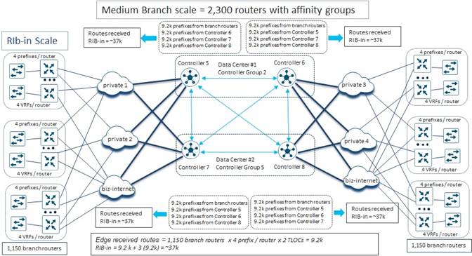
There are a total of 2,300 Medium-Sized Branch Sites within each overlay. Half of the Medium-Sized Branch Sites (1,150) are in the western side of the overlay, and therefore form DTLS/TLS control connections and OMP sessions to one SD-WAN Controller instance in Controller Group 2 and one SD-WAN Controller instance in Controller Group 5, in that order. The other half of the Medium-Sized Branch Sites (1,150) are in the eastern side of the overlay, and therefore form DTLS/TLS control connections and OMP sessions to one SD-WAN Controller instance in Controller Group 5 and one SD-WAN Controller instance in Controller Group 2, in that order.
For simplicity of the RIB-in calculations, all 1,150 Small Branch Site routers in the western side of the overlay are shown with OMP sessions to SD-WAN Controller 5 in Data Center #1 and SD-WAN Controller 6 in Data Center #2. Likewise, all 1,150 Medium-Sized Branch Site routers in the eastern side of the overlay are shown with OMP sessions to SD-WAN Controller 8 in Data Center #2 and SD-WAN Controller 6 in Data Center #1. In reality, the OMP sessions from Medium-Sized Branch Site routers to SD-WAN Controllers on both the western and eastern sides of the overlays would be balanced between SD-WAN Controller 5 and SD-WAN Controller 6 in Data Center #1 and between SD-WAN Controller 7 and SD-WAN Controller 8 in Data Center #2.
The number of routes received by each of the SD-WAN Controller instances in the figure above (SD-WAN Controller 5 through SD-WAN Controller 8) directly from the Medium-Sized Branch Site routers can again be calculated as follows:
Edge received routes = Number of routers (hub or spoke) with
OMP sessions to the SD-WAN Controller x
Number of prefixes sent per router x
Number of TLOCs per router
Substituting the numbers from the Medium-Sized Branch Sites yields the following:
Edge received routes = 1,150 Medium-Sized Branch routers x
4 IPv4 prefixes sent per Medium-Sized Branch router
2 TLOCs / Medium-Sized Branch router
= 9,200 IPv4 prefixes / routes
In addition, since all SD-WAN Controllers within a given overlay are fully meshed and exchange routes, each SD-WAN Controller instance will receive routes reflected from the other three SD-WAN Controller instances dedicated for the Medium-Sized Branch Sites, as well as the other SD-WAN Controller instances dedicated for the Small Branch Sites (SD-WAN Controller 1 through SD-WAN Controller 4), and for the Large / Regional Branch and Data Center Sites (SD-WAN Controller 9 through SD-WAN Controller 12).
If we look only at the reflected routes from other SD-WAN Controller instances dedicated for Medium-Sized Branch sites (SD-WAN Controller 5 through SD-WAN Controller 8), it can easily be seen that an additional 9,200 IPv4 prefixes are reflected by each of the other 3 SD-WAN Controller instances. Hence the total number of routes received by each SD-WAN Controller instance from the Edge devices (SD-WAN routers) and from the SD-WAN Controller instances dedicated to Medium-Sized Branch sites (SD-WAN Controller 5 through SD-WAN Controller 8) is as follows:
Received routes = 9,200 Edge received routes +
3 x 9,200 Reflected routes from Medium-Sized Branch
SD-WAN Controller instances
= 36,800 (~37k) Received routes
Note that the ~37 received routes for each of the SD-WAN Controller instances dedicated for the Medium-Sized Branch Sites does not yet consider the routes reflected by the SD-WAN Controller instances dedicated for the Small Branch Sites, and the SD-WAN Controller instances dedicated for the Large / Regional Branch and Data Center Sites.
Before adding those in, we must first calculate the number of edge received routes on each of the SD-WAN Controller instances dedicated for Large / Regional Branch Sites from SD-WAN routers connected to the Large / Regional Branch Site SD-WAN Controller instances.
Large / Regional Branch Site RIB-in Calculations – Partial
As discussed in the Branch Design section of this guide, each Large / Regional Branch Site consists of two SD-WAN routers, each configured with three TLOCs. Each SD-WAN router has two MPLS-based TLOCs (private1, private2, private3, or private4) and one Internet-based (biz-internet) TLOC. Each Large / Regional Branch Site supports up to six IPv4 prefixes advertised into OMP.

There are a total of 596 Large / Regional Branch Sites within each overlay. Half of the Large / Regional Branch Sites are in the western side of the overlay, and therefore form DTLS/TLS control connections and OMP sessions to one SD-WAN Controller instance in Controller Group 1 and one SD-WAN Controller instance in Controller Group 4, in that order. The other half of the Large / Regional Branch Sites (596) are in the eastern side of the overlay, and therefore form DTLS/TLS control connections and OMP sessions to one SD-WAN Controller instance in Controller Group 4 and one SD-WAN Controller instance in Controller Group 1, in that order.
| Technical Note: |
| Although there are a total of 596 Large / Regional Branch sites within each overlay, each Large / Regional Branch site consists of two SD-WAN routers. Hence, in the figure above 596 branch routers are OMP-peered with SD-WAN Controller instances on each side of the overlay. |
For simplicity of the RIB-in calculations, all 596 Large / Regional Site routers in the western side of the overlay are shown with OMP sessions to SD-WAN Controller 9 in Data Center #1 and SD-WAN Controller 11 in Data Center #2. Likewise, all 596 Large / Regional Branch Site routers in the eastern side of the overlay are shown with OMP sessions to SD-WAN Controller 12 in Data Center #2 and SD-WAN Controller 10 in Data Center #1. In reality, the OMP sessions from Large / Regional Branch Site routers to SD-WAN Controllers on both the western and eastern sides of the overlays would be balanced between SD-WAN Controller 9 and SD-WAN Controller 10 in Data Center #1 and between SD-WAN Controller 11 and SD-WAN Controller 12 in Data Center #2.
The number of routes received by each of the SD-WAN Controller instances directly from the Large / Regional Branch Site routers in the figure above (SD-WAN Controller 9 through SD-WAN Controller 12), can again be calculated as follows:
Edge received routes = Number of routers (hub or spoke) with
OMP sessions to the SD-WAN Controller x
Number of prefixes sent per router x
Number of TLOCs per router
Substituting the numbers from the Large / Regional Branch Sites yields the following:
Edge received routes = 596 Large / Regional Branch routers x
6 IPv4 prefixes sent per Large / Regional Branch router
3 TLOCs / Large / Regional Branch router
= 10,728 (~10.7k) IPv4 prefixes / routes
In addition, since all SD-WAN Controller instances within a given overlay are fully meshed and exchange routes, each SD-WAN Controller instance will receive routes reflected from the other three SD-WAN Controller instances dedicated for the Large / Regional Branch Sites, as well as the other SD-WAN Controller instances dedicated for the Small Branch Sites (SD-WAN Controller 1 through SD-WAN Controller 4), for the Medium-Sized Branch Sites (SD-WAN Controller 5 through SD-WAN Controller 8), and for the Data Center Sites (SD-WAN Controller 9 through SD-WAN Controller 12).
If we look only at the reflected routes from other SD-WAN Controller instances dedicated for Large / Regional Branch sites (SD-WAN Controller 9 through SD-WAN Controller 12), it can easily be seen that an additional ~10.7k IPv4 prefixes are reflected by each of the other three SD-WAN Controller instances. Hence the total number of routes received by each SD-WAN Controller instance from the Edge devices (SD-WAN routers) and from the SD-WAN Controller instances dedicated to Large / Regional Branch sites (SD-WAN Controller 9 through SD-WAN Controller 12) is as follows:
Received routes = ~10.7k Edge received routes +
3 x ~10.7k Reflected routes from Large/Regional
Branch SD-WAN Controller instances
= 42,912 (~43k) Received routes
Note that the ~43K received routes for each of the SD-WAN Controller instances dedicated for the Large / Regional Branch Sites does not yet consider the routes reflected by the SD-WAN Controller instances dedicated for the Small Branch Sites, the SD-WAN Controller instances dedicated for the Medium-Sized Branch Sites, and the SD-WAN Controller instances used by the Data Center Sites.
Before adding those in, we must first calculate the number of edge received routes on each of the SD-WAN Controller instances used by the Data Center Sites from SD-WAN routers connected to the Data Center Site SD-WAN Controller instances.
Data Center (Hub) Site RIB-in Calculations – Partial
As discussed in the Branch Design section of this guide, each Data Center (Hub) Site consists of four SD-WAN routers, each configured with five TLOCs. Each SD-WAN router has four MPLS-based TLOCs (private1, private2, private3, and private4) and one Internet-based (biz-internet) TLOC. Each Data Center (Hub) Site supports up to 30 IPv4 prefixes advertised into OMP.
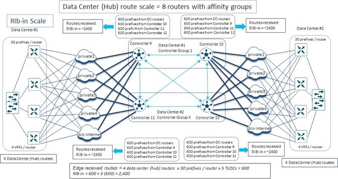
There are 2 Data Center (Hub) sites within each overlay. One of the Data Center (Hub) Sites is in the western side of the overlay. SD-WAN routers within that site form DTLS/TLS control connections and OMP sessions to one SD-WAN Controller instance in Controller Group 1 and one SD-WAN Controller instance in Controller Group 4, in that order. The other Data Center (Hub) Site is in the eastern side of the overlay. SD-WAN routers within that site form DTLS/TLS control connections and OMP sessions to on SD-WAN Controller instance in Controller Group 4 and one SD-WAN Controller instance in Controller Group 1, in that order.
For simplicity of the RIB-in calculations, all Data Center (Hub) Site routers in the western side of the overlay are shown with OMP sessions to SD-WAN Controller 9 in Data Center #1 and SD-WAN Controller 11 in Data Center #2. Likewise, all Data Center (Hub) Site routers in the eastern side of the overlay are shown with OMP sessions to SD-WAN Controller 12 in Data Center #2 and SD-WAN Controller 10 in Data Center #1. In reality, the OMP sessions from Data Center (Hub) Site routers to SD-WAN Controllers on both the western and eastern sides of the overlays would be balanced between SD-WAN Controller 9 and SD-WAN Controller 10 in Data Center #1 and between SD-WAN Controller 11 and SD-WAN Controller 12 in Data Center #2.
The number of routes received by each of the SD-WAN Controller instances in the figure above (SD-WAN Controller 9 through SD-WAN Controller 12) directly from the Data Center (Hub) Site routers can again be calculated as follows:
Edge received routes = Number of routers (hub or spoke) with
OMP sessions to the SD-WAN Controller x
Number of prefixes sent per router x
Number of TLOCs per router
Substituting the numbers from the Data Center (Hub) Sites yields the following:
Edge received routes = 4 Data Center (Hub) Site routers x
30 IPv4 prefixes sent per Data Center (Hub) Site router
5 TLOCs / Data Center (Hub) Site router
= 600 IPv4 prefixes / routes
In addition, since all SD-WAN Controllers within a given overlay are fully meshed and exchange routes, each SD-WAN Controller instance will receive routes reflected from the other three SD-WAN Controller instances dedicated for the Data Center (Hub) Sites, as well as the other SD-WAN Controller instances dedicated for the Small Branch Sites (SD-WAN Controller 1 through SD-WAN Controller 4), for the Medium-Sized Branch Sites (SD-WAN Controller 5 through SD-WAN Controller 8), and for the Large / Regional Sites (SD-WAN Controller 9 through SD-WAN Controller 12).
If we look only at the reflected routes from other SD-WAN Controller instances dedicated for Data Center (Hub) sites (SD-WAN Controller 9 through SD-WAN Controller 12), it can easily be seen that an additional 600 IPv4 prefixes are reflected by each of the other three SD-WAN Controller instances. Hence the total number of routes received by each SD-WAN Controller instance from the Edge devices (SD-WAN routers) and from the SD-WAN Controller instances dedicated to Data Center (Hub) Sites (SD-WAN Controller 9 through SD-WAN Controller 12) is as follows:
Received routes = 600 Edge received routes +
3 x 600 Reflected routes from Data Center (Hub)
SD-WAN Controller instances
= 2,400 Received routes
Note that the 2,400 received routes for each of the SD-WAN Controller instances dedicated for the Data Center (Hub) Sites does not yet consider the routes reflected by the SD-WAN Controller instances dedicated for the Small Branch Sites, the SD-WAN Controller instances dedicated for the Medium-Sized Branch Sites, and the SD-WAN Controller instances used by the Large / Regional Branch Sites.
The next section completes the calculation of routes received, and hence the RIB-in size for each of the SD-WAN Controllers in each overlay within the Bank of the Earth design.
Combined Routes Received (RIB-in) Calculations
In the previous section, the routes received directly from edge devices (SD-WAN routers) was discussed for each site type (Small Branch, Medium-Sized Branch, Large / Regional Branch, and Data Center). Since four SD-WAN Controller instances are dedicated to each site type in the Bank of the Earth design, the routes reflected from the other three SD-WAN Controller instances were also discussed. For example, in the figure below, for SD-WAN Controller 1 there are 5,000 directly connected routes (routes from Edge devices). In addition, there are 5,000 routes from each of the other three SD-WAN Controller instances (SD-WAN Controller 2, SD-WAN Controller 3, and SD-WAN Controller 4) reflected to SD-WAN Controller 1 – since each of the other three SD-WAN Controller instances also have 5,000 directly connected routes – for a total of 20,000 received routes.
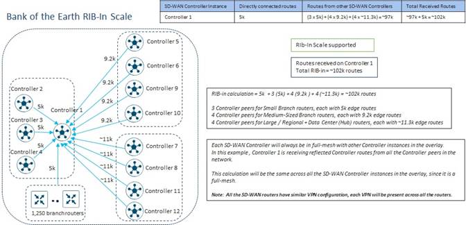
Since all SD-WAN Controller instances within an overlay are fully meshed, we must also consider all the routes reflected by the SD-WAN Controller instances dedicated for each of the other site types (Medium-Sized Branch, Large / Regional Branch, and Data Center). Each of the SD-WAN Controller instances dedicated for the Medium-Sized Branch Sites (SD-WAN Controller 5 through SD-WAN Controller 8) have 9,200 received routes. These are each reflected to SD-WAN Controller 1. Hence, this adds a total of 4 x 9,200 = 36,800 or ~37k additional receive routes to SD-WAN Controller 1. Likewise, each of the SD-WAN Controller instances dedicated for the Large / Regional Branch and the Data Center Sites (SD-WAN Controller 9 through SD-WAN Controller 12) have a total of 10,728 + 600 = 11,328 or ~11k received routes. These are also reflected to SD-WAN Controller 1. Hence, this adds a total of 4 x ~11k = ~48k routes to SD-WAN Controller 1.
Hence the total number of routes received by SD-WAN Controller 1 can be calculated as follows:
Received routes = 5,000 Edge received routes +
3 x 5,000 Reflected routes from other Small Branch
SD-WAN Controller instances +
4 x 9,200 Reflected routes from Medium-Sized
SD-WAN Controller instances +
4 x 11,328 Reflected routes from Large/Regional & Data Center
SD-WAN Controllers
= 5,000 + 15,000 + 36,800 + 45,312 = 102,112 or ~102k Received Routes
Hence the RIB-in table for SD-WAN Controller 1 will need to hold ~102k received routes.
The same mental exercise can be done for each of the other SD-WAN Controller instances within the overlay. However, an alternative way of looking at the same received routes calculation is shown in the figure below.
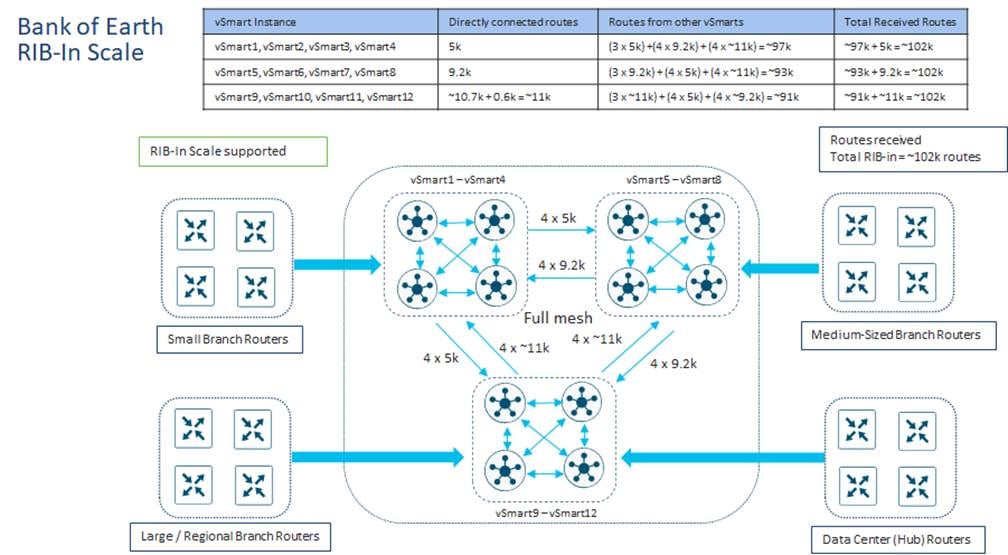
In the figure above, we can take the partial receive routes calculated for each of the site types (Small Branch, Medium Branch, or combined Large / Regional Branch and Data Center) in the sections above. For example, it was determined that there were 5,000 directly connected routes for each of the SD-WAN Controller instances dedicated to the Small Branch Sites (SD-WAN Controller 1 through SD-WAN Controller 4) plus 5,000 reflected routes from each of the other SD-WAN Controller instances – for a total of 20,000 received routes. We can simply add 4 x 9,200 reflected routes from the four SD-WAN Controller instances which are dedicated to the Medium-Sized Branch Sites (SD-WAN Controller 5 through SD-WAN Controller 8) and 4 x ~11k reflected routes from the four SD-WAN Controller instances which are dedicated to the Large / Regional Branch and Data Center Sites (SD-WAN Controller 9 through SD-WAN Controller 12) to the calculation of the received routes of the SD-WAN Controllers dedicated to the Small Branch Sites (SD-WAN Controller 1 through SD-WAN Controller 4). This sums to the following:
Received routes = 4 x 5,000 Edge + reflected routes from Small Branch SD-WAN
Controllers + 4 x 9,200 reflected routes from Medium-Sized
Branch SD-WAN Controllers + 4 x 11,328 Reflected routes from
Large/Regional and Data Center SD-WAN Controllers
= 20,000 + 36,800 + 45,312 = 102,112 or ~102k Received Routes
As can be seen in the figure above, since all SD-WAN Controller instances within the overlay are fully meshed, each of the SD-WAN Controller instances will have the same number of received routes (~102k) within the Bank of the Earth design. Hence, each of the SD-WAN Controller instances within each of the Bank of the Earth overlays will need to support up to ~102k received routes. More specifically, each SD-WAN Controller instance will need to have sufficient memory to support a RIB-in table with ~102k received routes. After consulting with their Cisco account team, Bank of the Earth determined that this was within the recommended RIB-in scale supported for SD-WAN Controller instances.
Routes Sent (RIB-out) Calculations and Scale
Routes Sent (RIB-out) Calculation for Full-Mesh Deployment
Although Bank of the Earth did not implement a full-mesh fabric data plane topology, they went through the exercise of determining the routes sent (RIB-out) from each SD-WAN Controller instance, to understand how the calculations are performed. In a full-mesh deployment, it is assumed that no centralized policy is applied to the SD-WAN Controller instances that will affect the sending and receiving of OMP routes from the SD-WAN Controller instances.
The routes sent (RIB-out) calculation for each SD-WAN Controller instance in a full-mesh topology consists of the following three components:
● Edge routes received from SD-WAN routers that are OMP-peered with the SD-WAN Controller instance, which are then reflected to the other SD-WAN Controller instances within the overlay – since all SD-WAN Controller instances in an overlay are OMP-peered with each other. This can be expressed with the following equation:
a x b
where a = Edge received routes
= (Number of routers with OMP sessions to the SD-WAN Controller) x
(prefixes per router) x (TLOCs)
and b = Number of SD-WAN Controller peers to the given SD-WAN Controller instance
● Edge routes received from SD-WAN routers that are OMP-peered with the SD-WAN Controller instance, which are then reflected to other SD-WAN routers that are OMP-peered with the same SD-WAN Controller instance. This can be expressed with the following equation:
a x (n – 1)
where a = Edge received routes
= (number of routers OMP peered with the SD-WAN Controller instance) x
(prefixes per router) x (TLOCs)
and n = number of router peers to the given SD-WAN Controller instance
Note that a SD-WAN Controller instance will not reflect OMP routes sent from a given SD-WAN router back to the same router. For example, given there are 1,250 SD-WAN routers with OMP sessions to SD-WAN Controller 1, an OMP route / prefix sent to SD-WAN Controller 1 from one router will be reflected to the other 1,249 routers which are OMP-peered with SD-WAN Controller 1.
● The sum of the SD-WAN Controller received routes from the other SD-WAN Controller instances within the overlay, which are then reflected by the SD-WAN Controller instance to any SD-WAN routers OMP-peered with the given SD-WAN Controller instance. This can be expressed with the following equation:
c x n
where c = ⅀(Number of routers not directly connected to the SD-WAN Controller
instance) x(prefixes per router) x (number of TLOCs per router)
and n = number of router peers to the given SD-WAN Controller instance
Small Branch Site Routes Sent (RIB-out) Calculations – Full-Mesh
The following are the calculations for determining routes sent (RIB-out) for each of the SD-WAN Controller instances dedicated for Small Branch Sites within the Bank of the Earth deployment – assuming a full-mesh deployment.
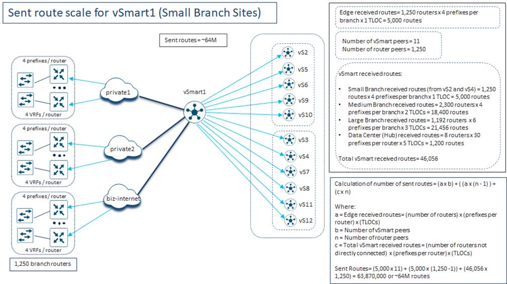
In the Routes Received (RIB-in) Calculations and Scale section of this guide, the number of routes received by each of the SD-WAN Controller instances from the Small Branch routers (SD-WAN Controller 1 through SD-WAN Controller 4) which have OMP peering relationships directly with the SD-WAN Controller instances was calculated. Substituting the numbers from the Small Branch Sites connected to SD-WAN Controller 1 yields the following:
Edge received routes = 1,250 Small Branch routers x
4 IPv4 prefixes sent per Small Branch router x
1 TLOC / Small Branch router
= 5,000 IPv4 prefixes / routes
These edge received routes are reflected by SD-WAN Controller 1 to each of the other SD-WAN Controller instances within the overlay. In the example above (and in each Bank of the Earth overlay) there are a total of 12 SD-WAN Controller instances, and therefore SD-WAN Controller 1 has 11 peers. Hence, the first component of the routes sent (RIB-out) calculation for SD-WAN Controller 1 is as follows:
a x b = (Edge received routes) x (Number of SD-WAN Controller peers to the
given SD-WAN Controller instance)
= 5,000 x 11 = 55,000 routes
The edge received routes are also reflected from SD-WAN Controller 1 to each of the 1,250 directly connected SD-WAN routers. However, as noted above, a SD-WAN Controller will not reflect the OMP routes sent by a specific SD-WAN router back to the same SD-WAN router. So, in other words the OMP routes sent by one Small Branch router are reflected to the 1,249 other Small Branch routers which have OMP peering sessions with SD-WAN Controller 1. Hence, the second component of the routes sent (RIB-out) calculation for SD-WAN Controller 1 is as follows:
a x (n – 1) = (Edge received routes x
(number of router peers to the given SD-WAN Controller instance)
= 5,000 x 1,249 = 6,245,000 routes
Next, we need to account for the edge received routes from other SD-WAN Controller instances in the network which are reflected to SD-WAN Controller 1 and, in turn, reflected to the 1,250 SD-WAN routers OMP-peered with SD-WAN Controller 1.
The number of edge receive routes which will be reflected from each of the SD-WAN Controller peers is shown in the following calculations.
Small Branches (SD-WAN Controller 2 and SD-WAN Controller 4)
c_small = (Number of routers not directly connected to the SD-WAN Controller
instance) x (prefixes per router) x (number of TLOCs per router)
= 1,250 x 4 x 1 = 5,000 routes
Medium Branches (SD-WAN Controller 5 through SD-WAN Controller 8)
c_medium = (Number of routers not directly connected to the SD-WAN Controller
instance) x (prefixes per router) x (number of TLOCs per router)
= 2,300 x 4 x 2 = 18,400 routes
Large/Regional Branches (SD-WAN Controller 9 through SD-WAN Controller 12)
c_large = (Number of routers not directly connected to the SD-WAN Controller
instance) x (prefixes per router) x (number of TLOCs per router)
= 1,192 x 6 x 3 = 21,456 routes
Data Center (Hub) Sites (SD-WAN Controller 9 through SD-WAN Controller 12)
c_data = (Number of routers not directly connected to the SD-WAN Controller
instance) x (prefixes per router) x (number of TLOCs per router)
= 8 x 30 x 5 = 1,200 routes
Total received routes reflected by SD-WAN Controller 1 = c = 5,000 + 18,400 + 21,456
+ 1,200 = 46,056
These routes are then reflected to each of the 1,250 SD-WAN routers which have OMP-peering sessions with SD-WAN Controller 1. Hence the routes from the third component can be calculated as follows:
c x n = 46,056 routes x 1,250 SD-WAN routers = 57,570,000
Finally, the total routes sent (RIB-out) from SD-WAN Controller 1 can be calculated by summing the three components as follows:
55,000 + 6,245,000 + 57,570,000 = 63,870,000 or ~64M routes sent
Hence, the number of routes sent (size of the RIB-out table) is ~64M routes for SD-WAN Controller 1. In other words, there must be sufficient memory within SD-WAN Controller 1 to handle ~64M routes sent.
With the Bank of the Earth SD-WAN Controller design, SD-WAN Controller 1 through SD-WAN Controller 4 are dedicated to Small Branch Sites. The design also assumes approximately equal distribution of OMP sessions from Small Branch Site routers across all four SD-WAN Controller instances. Hence, based on these constraints, it can be assumed that each SD-WAN Controller instance from SD-WAN Controller 1 through SD-WAN Controller 4 will need to support ~64M routes sent (RIB-out).
Medium-Sized Branch Site Routes Sent (RIB-out) Calculations – Full-Mesh
The same logic can be applied to calculate routes sent (RIB-out) for each SD-WAN Controller instance dedicated to Medium-Sized Branch Sites, as shown in the following figure.
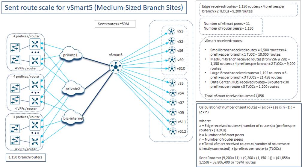
As show in the figure above, the number of routes sent (size of the RIB-out table) is ~59M routes for SD-WAN Controller 5. Since SD-WAN Controller 5 through SD-WAN Controller 8 are dedicated to Medium-Sized Branch Sites, and the Bank of the Earth SD-WAN Controller design assumes approximately equal distribution of OMP sessions from Medium-Sized Branch Site routers across all four SD-WAN Controller instances, each of these SD-WAN Controller instances must have sufficient memory to handle ~59M routes sent.
Large / Regional Branch and Data Center Site Routes Sent (RIB-out) Calculations – Full-mesh
Finally, the same logic can again be applied to the SD-WAN Controller instances dedicated to Large / Regional Branch Sites and Data Center Sites, as shown in the figure below.
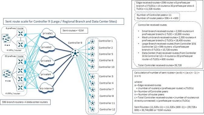
Again, using the same calculations as were used for the SD-WAN Controller instances dedicated for Small Branch Sites and Medium-Sized Branch Sites, the number of routes sent (RIB-out) for the SD-WAN Controller instances dedicated for Large / Regional Branch Sites and Data Center Sites can also be calculated. As show in the figure above, the number of routes sent (size of the RIB-out table) is ~31M routes for SD-WAN Controller 9. Since SD-WAN Controller 9 through SD-WAN Controller 12 are dedicated to Large / Regional Branch Sites and Data Center Sites, and the Bank of the Earth SD-WAN Controller design assumes approximately equal distribution of OMP sessions from Large / Regional Branch Site and Data Center Site routers across all four SD-WAN Controller instances, each of these SD-WAN Controller instances must have sufficient memory to handle ~31M routes sent.
Summary of Routes Sent (RIB-out) Calculations – Full Mesh
The following figure summarizes the routes sent (RIB-out) calculations for all SD-WAN Controller instances in the Bank of the Earth deployment – in a full-mesh scenario.
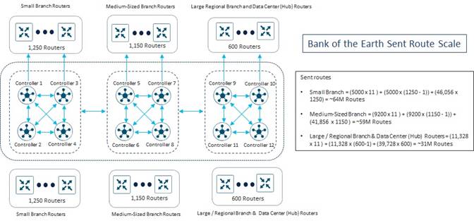
After discussing the routes sent (RIB-out) scale for each of the SD-WAN Controller instances in a full-mesh deployment with their Cisco account team, Bank of the Earth was able to determine that the route scale was within the recommended guidelines for maximum routes sent per SD-WAN Controller instance.
Scenario Analysis
Even though Bank of the Earth was satisfied that under normal operating conditions with a full-mesh fabric data plane topology, each SD-WAN Controller would be able to handle the number of routes received (RIB-in) and routes sent (RIB-out), they also analyzed the effects of various scenarios on OMP route scale.
Data Center Failure
The first scenario that Bank of the Earth looked at was what effect would a data center failure have on the routes received (RIB-in) and routes sent (RIB-out) calculations of the SD-WAN Controller instances within the overlay.
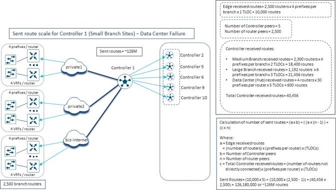
Routes Received (RIB-in) Calculations
In the event of a data center failure, only half the SD-WAN Controller instances would be available in the overlay. As shown in the figure above, all 2,500 Small Branch routers would now have OMP peering relationships with SD-WAN Controller 1. The number of edge routes received for SD-WAN Controller 1 can now be calculated as follows:
Edge received routes = 2,500 Small Branch routers x
4 IPv4 prefixes sent per Small Branch router x
1 TLOC / Small Branch router
= 10,000 IPv4 prefixes / routes
As we can see, the number of edge received routes has doubled because the number of WAN edge devices OMP peered with SD-WAN Controller 1 has also doubled. This will be the same for all the other SD-WAN Controller instances in the overlay with the Bank of the Earth design. Note however, that with the failure of a data center, the number of routes received from the SD-WAN Controller instances which serve that data center site will need to be reduced by the number of routes sent by that data center site. Hence, the total number of routes received by SD-WAN Controller 1 can be calculated as follows:
Received routes = 10,000 Edge received routes + 1 x 10,000 Reflected routes from
other Small Branch SD-WAN Controller instances + 2 x 18,400
Reflected routes from Medium-Sized SD-WAN Controller instances +
2 x (22,656 – 600) Reflected routes from Large/Regional &
Data Center SD-WAN Controllers
= 10,000 + 10,000 + 36,800 + 44,112 = 100,912 or ~101k Received Routes
As can be seen, a data center failure does not significantly change the number of routes received (RIB-in) for SD-WAN Controller 1, or for that matter for any of the remaining SD-WAN Controller instances within the overlay, with the Bank of the Earth design.
Routes Sent (RIB-out) Calculations
As discussed in the previous section, in the event of a data center failure, the number of edge routes received for SD-WAN Controller 1 can now be calculated as follows:
Edge received routes = 2,500 Small Branch routers x
4 IPv4 prefixes sent per Small Branch router x
1 TLOC / Small Branch router
= 10,000 IPv4 prefixes / routes
These edge received routes are reflected by SD-WAN Controller 1 to each of the other SD-WAN Controller instances within the overlay. With a data center failure there are a total of 6 remaining SD-WAN Controller instances, and therefore SD-WAN Controller 1 has 5 peers. Hence, the first component of the routes sent (RIB-out) calculation for SD-WAN Controller 1 is as follows:
a x b = (Edge received routes) x (Number of SD-WAN Controller peers to the
given SD-WAN Controller instance)
= 10,000 x 5 = 50,000 routes
The edge received routes are also reflected from SD-WAN Controller 1 to each of the 2,500 directly connected SD-WAN routers. However, as noted above, a SD-WAN Controller will not reflect the OMP routes sent by a specific SD-WAN router back to the same SD-WAN router. So, in other words the OMP routes sent by one Small Branch router are reflected to the 2,499 other Small Branch routers which have OMP peering sessions with SD-WAN Controller 1. Hence, the second component of the routes sent (RIB-out) calculation for SD-WAN Controller 1 is as follows:
a x (n – 1) = (Edge received routes x
(number of router peers to the given SD-WAN Controller instance)
= 10,000 x 2,499 = 24,990,000 routes
Next, we need to account for the edge received routes from other SD-WAN Controller instances in the network which are reflected to SD-WAN Controller 1 and, in turn, reflected to the 2,500 SD-WAN routers OMP-peered with SD-WAN Controller 1.
The number of edge receive routes which will be reflected from each of the SD-WAN Controller peers is shown in the following calculations.
Medium Branches (SD-WAN Controller 5 through SD-WAN Controller 6)
c_medium = (Number of routers not directly connected to the SD-WAN Controller
instance) x (prefixes per router) x (number of TLOCs per router)
= 2,300 x 4 x 2 = 18,400 routes
Large/Regional Branches (SD-WAN Controller 9 through SD-WAN Controller 10)
c_large = (Number of routers not directly connected to the SD-WAN Controller
instance) x (prefixes per router) x (number of TLOCs per router)
= 1,192 x 6 x 3 = 21,456 routes
Data Center (Hub) Sites (SD-WAN Controller 9 through SD-WAN Controller 10)
c_data = (Number of routers not directly connected to the SD-WAN Controller
instance) x (prefixes per router) x (number of TLOCs per router)
= 4 x 30 x 5 = 600 routes
Total received routes reflected by SD-WAN Controller 1 = 18,400 + 21,456 + 600 = 40,456
These routes are then reflected to each of the 2,500 SD-WAN routers which have OMP-peering sessions with SD-WAN Controller 1. Hence the routes from the third component can be calculated as follows:
c x n = 40,456 routes x 2,500 SD-WAN routers = 101,140,000
Finally, the total routes sent (RIB-out) from SD-WAN Controller 1 can be calculated by summing the three components as follows:
50,000 + 24,990,000 + 101,140,000 = 126,180,000 or ~126M routes sent
Hence, the number of routes sent (size of the RIB-out table) has nearly doubled and is ~126M routes for SD-WAN Controller 1. In other words, there must be sufficient memory within SD-WAN Controller 1 to handle ~126M routes sent. After, discussing this with their Cisco account team, Bank of the Earth confirmed that this number of routes sent (RIB-out) exceeds the recommended maximum for SD-WAN Controller instances.
Decreasing the Number of SD-WAN Controller Instances per Overlay
The date center failure scenario just discussed can be extended to evaluate the effects on routes received (RIB-in) and routes sent (RIB-out) on SD-WAN Controller instances, when alternative designs involving less SD-WAN Controller instances within the overlay are considered.
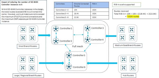
As can be seen in the figure above, decreasing the number of SD-WAN Controller instances from 12 to 6 in the Bank of the Earth overlay design, has no effect on the number of routes received (RIB-in) of each individual SD-WAN Controller instance.
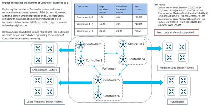
However, as can be seen in the figure above, decreasing the number of SD-WAN Controller instances from 12 to 6 in the Bank of the Earth overlay design, has the effect of doubling the number of routes sent (RIB-out) of each individual SD-WAN Controller instance. Note that the figure above does not consider whether the maximum number of DTLS/TLS control connections or the maximum number of OMP sessions per SD-WAN Controller has been exceeded.
Hence, Bank of the Earth realized from the analysis of decreasing the number of SD-WAN Controller instances in the network (either resulting from a data center failure or simply based on design) that it influences the scalability of the SD-WAN Controller instances, in terms of routes received (RIB-in) and routes sent (RIB-out) – particularly routes sent (RIB-out) with their design. Also, the scalability of the SD-WAN Controller instances, with respect to the maximum number of recommended DTLS/TLS control connections and the number of OMP sessions per instance, must be balanced against the maximum recommended routes received (RIB-in) and routes sent (RIB-out) per instance – when considering the number of SD-WAN Controller instances within the overlay and the Affinity design.
Increasing the Number of Prefixes per Site
The final scenario that Bank of the Earth looked at was what effect would increasing the number of prefixes sent from the branch site routers have on the routes received (RIB-in) and routes sent (RIB-out) of the SD-WAN Controller instances within the overlay.
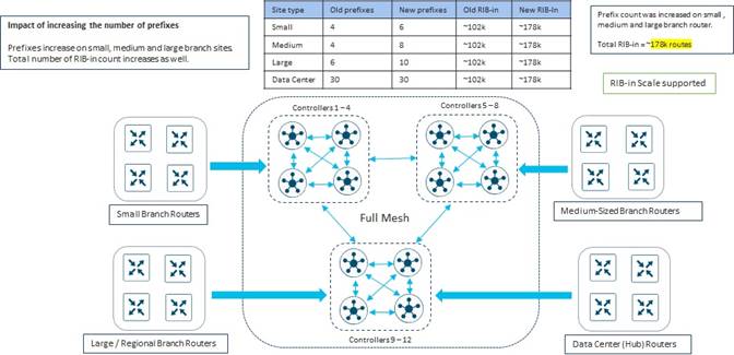
In the figure above, the number of unicast IPv4 prefixes sent per Small Branch site has been increased from 4 to 6. Likewise, the number of unicast IPv4 prefixes sent per Medium-Sized Branch site has been doubled from 4 to 8. Finally, the number of unicast IPv4 prefixes sent per Large / Regional Branch site has been increased from 6 to 10. The number of unicast IPv4 prefixes sent from the Data Center (hub) Sites remains at 30.
Bank of the Earth re-calculated the number of routes received per SD-WAN Controller and, as shown in the figure above, found that the routes received (RIB-in) per SD-WAN Controller instance increased from ~102K routes to ~178K routes. After consulting with their Cisco account team, it was determined that this was still within the recommendations for maximum routes received (RIB-in) per SD-WAN Controller instance.
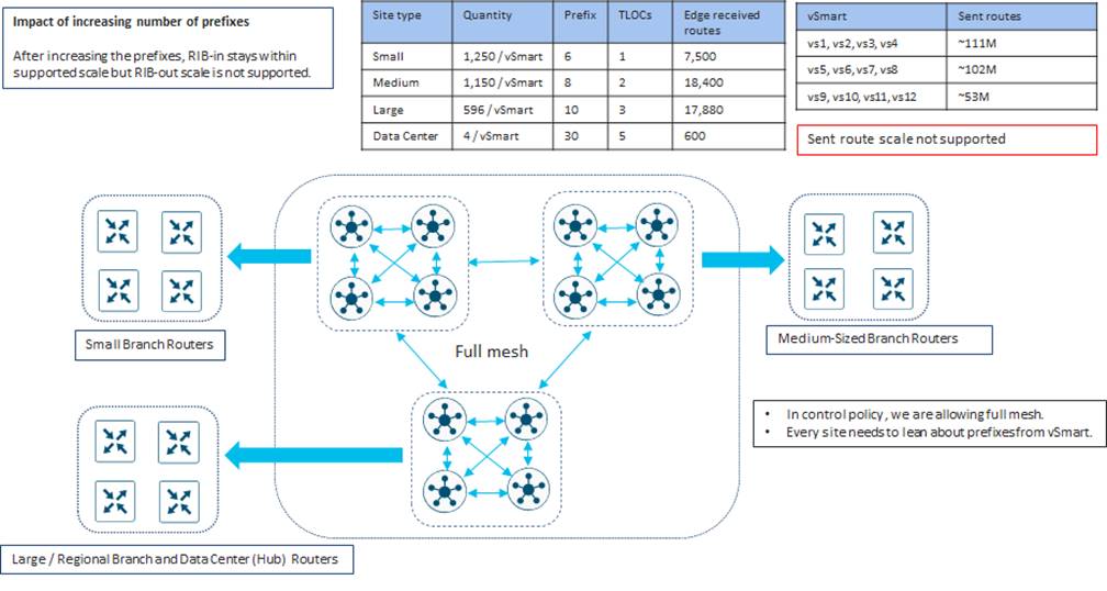
Bank of the Earth also re-calculated the number of routes sent per SD-WAN Controller. As shown in the figure above, they found that the routes sent (RIB-out) per SD-WAN Controller instance increased. For the SD-WAN Controller instances which are dedicated to the Small Branch sites (SD-WAN Controller 1 through SD-WAN Controller 4), the routes sent (RIB-out) increased from ~64M routes to ~111M routes. For the SD-WAN Controller instances which are dedicated to the Medium-Sized Branch sites (SD-WAN Controller 5 through SD-WAN Controller 8), the routes sent (RIB-out) increased from ~59M routes to ~102M routes. Finally, for the SD-WAN Controller instances which are dedicated to the Large / Regional Branch and Data Center sites (SD-WAN Controller 9 through SD-WAN Controller 12), the routes sent (RIB-out) increased from ~31M routes to ~53M routes.
What Bank of the Earth gleaned from this analysis was that even a small increase in the number of prefixes sent per branch site, can cause a large increase in the number of OMP routes – particularly routes sent – when there are many branches within the overlay. This could cause individual SD-WAN Controller instances to exceed the maximum recommended number of routes sent (RIB-out).
After consulting with their Cisco account team, it was determined that the routes sent (RIB-out) for the SD-WAN Controller instances dedicated for Small Branch sites (SD-WAN Controller 1 through SD-WAN Controller 4) and the SD-WAN Controller instances dedicated for Medium-Sized Branch sites (SD-WAN Controller 5 through SD-WAN Controller 8) would in fact exceed the recommendations for maximum routes sent (RIB-out) per SD-WAN Controller instance – if the number of prefixes were to be increased as shown in the figure above. This also highlighted to Bank of the Earth the importance of carefully selecting the IP addressing of each branch site such that individual IPv4 subnets can be aggregated into a smaller number of prefixes advertised into OMP from each branch.
Routes Sent (RIB-out) Calculation for Hub-and-Spoke Deployment
Although the previous section served as a nice mental exercise for Bank of the Earth to calculate the size of the routes sent (RIB-out) for each SD-WAN Controller instance within their deployment, as discussed in the Network Topology (Fabric and Service VPN Data Planes) section of this guide, Bank of the Earth implemented a hub-and-spoke fabric data plane topology for the each of the SD-WAN overlays within their overall network. This was primarily due to the total number of sites within each overlay and the tunnel capacity of the SD-WAN router platforms – primarily the branch router platforms.
Bank of the Earth realized that they had a choice in how to implement the hub-and-spoke topology, using the following techniques:
● Use centralized control policy to re-write the TLOC through which each branch OMP prefix / route is reachable. Using this method, the TLOC of the branch router is replaced with one or more TLOCs which represent the data center hub routers. The specific branch prefixes are still reflected by the SD-WAN Controller instances to each branch router, but the TLOC through which the branch prefixes are reachable has been changed to the data center hub routers. All branch-to-branch (spoke-to-spoke) traffic is sent first to a data center hub routers, which hairpins the traffic back to the destination branch router.
● Use centralized control policy to filter out the branch prefixes / routes from being reflected by the SD-WAN Controller instances to each branch router. Instead send only the data center hub prefixes / routes along with a default route reachable via the TLOCs of the data center hub routers. The branch prefixes still need to be reflected to the data center hub routers, but not to the branch routers. All branch-to-branch (spoke-to-spoke) traffic is again sent to the data center hub routers due to the default route reachable via the data center hub router TLOCs. From there, since the data center hub routers have visibility to all branch prefixes / routes, the traffic is hair-pinned back to the destination branch router.
| Technical Note: |
| Routes received (RIB-in) per SD-WAN Controller instance is assumed to be the same regardless of whether a full-mesh or hub-and-spoke topology is implemented. This is because typically the centralized control policy used to implement a hub-and-spoke fabric data plane is applied outbound to the SD-WAN Controller instances and does not affect the routes sent between SD-WAN Controller instances - since the SD-WAN Controller instances are not within the Site ID ranges affected by the centralized control policy. |
Note that these two methods are not mutually exclusive within a single SD-WAN overlay. In other words, a combination of sending a default route to certain branch sites and sending TLOC re-write to other branch sites can be implemented.
Hub-and-Spoke Topology using TLOC Rewrite
Bank of the Earth first looked at the calculations for routes sent (RIB-out) when a hub-and-spoke topology was implemented using centralized control policy (applied outbound on the SD-WAN Controller instances) to rewrite the TLOCs through which the routes / prefixes of the branch sites were reachable.
With this type of centralized control policy, the routes sent (RIB-out) calculation for each SD-WAN Controller instance consist of the following seven components:
● Edge routes received from SD-WAN routers (hub or spoke) that are OMP-peered with the SD-WAN Controller instance, which are then reflected to the other SD-WAN Controller instances within the overlay – since all SD-WAN Controller instances in an overlay are OMP-peered with each other. This can be expressed with the following equation:
a x b
where a = Edge received routes
= (Number of SD-WAN routers with OMP sessions to the SD-WAN Controller) x
(prefixes per router) x (TLOCs)
and b = Number of SD-WAN Controller peers to the given SD-WAN Controller instance
Note that centralized policy using TLOC re-write is generally applied outbound on SD-WAN Controller instances against the site-IDs of the spoke sites and the hub sites. Since SD-WAN Controller instances are not part of these site-IDs, the TLOC re-write policy does not apply to routes sent between SD-WAN Controller instances.
● Edge routes received from spoke SD-WAN routers that are OMP-peered with the SD-WAN Controller instance, which are then reflected to other spoke SD-WAN routers that are OMP-peered with the same SD-WAN Controller instance. This is similar to the full-mesh scenario, except that with TLOC rewrite policy, the TLOC through which the spoke prefix is reachable is replaced with one or more TLOCs of the hub routers. This can be expressed with the following equation:
a_spoke x t x (n_spoke – 1)
where a_spoke = Spoke edge received routes
= (number of spoke / branch routers OMP peered with the SD-WAN
Controller instance) x (prefixes per router) x (TLOCs)
and t = Number of hub TLOCs through which the spoke edge received routes will be
advertised to be available through
and n_spoke = number of spoke router peers to the given SD-WAN Controller instance
Note that a SD-WAN Controller instance will not reflect OMP routes sent from a given SD-WAN router back to the same router. For example, given there are 1,250 SD-WAN routers with OMP sessions to SD-WAN Controller 1, an OMP route / prefix sent to SD-WAN Controller 1 from one router will be reflected to the other 1,249 routers which are OMP-peered with SD-WAN Controller 1.
The number of data center (hub) TLOCs through which the Edge received routes will be advertised to be available through depends on the design of the network and the centralized control policy. Specifically, the number of available hub TLOCs is dependent on the number of Data Center sites, the number of SD-WAN routers per Data Center Site, and whether the specific SD-WAN router within the Data Center Site has a TLOC which can be used in the re-write policy. For the Bank of the Earth design, there are a total of 8 possible Data Center (hub) SD-WAN routers, each of which has all the available TLOCs. Hence, Bank of the Earth looked at a design using all 8 Data Center (hub) TLOCs in the re-write policy. In other words, each branch prefix was advertised to be available via all 8 Data Center (hub) TLOCs, after the centralized control policy was applied outbound on the SD-WAN Controller instances.
● Edge routes received from spoke SD-WAN routers that are OMP-peered with the SD-WAN Controller instance, which are then reflected to hub SD-WAN routers that are OMP-peered with the same SD-WAN Controller instance. It is assumed that TLOC rewrite policy does not apply to spoke routes sent to hub sites. This can be expressed with the following equation:
a_spoke x n_hub
where a_spoke = Spoke edge received routes
= (number of spoke / branch routers OMP peered with the SD-WAN
Controller instance) x (prefixes per router) x (TLOCs)
and n_hub = Number of hub routers OMP peered with the SD-WAN Controller instance
● Edge routes received from hub SD-WAN routers that are OMP-peered with the SD-WAN Controller instance, which are then reflected to spoke SD-WAN routers that are OMP-peered with the same SD-WAN Controller instance. This is similar to the previous component except that TLOC rewrite policy is assumed to not apply to hub routers. This can be expressed with the following equation:
a_hub x n_spoke
where a_hub = Hub edge received routes
= (number of hub routers OMP peered with the SD-WAN Controller instance)
x (prefixes per router) x (TLOCs)
and n_spoke = number of spoke router peers to the given SD-WAN Controller instance
● Next, we need to account for the spoke edge received routes from other SD-WAN Controller instances in the network which are reflected to the SD-WAN Controller instance and, in turn, reflected to the spoke SD-WAN routers OMP-peered with the SD-WAN Controller. Again, this is like the full-mesh scenario, except that with TLOC rewrite policy, the TLOC through which the spoke prefix is reachable is replaced with the TLOCs of the hub routers. This can be expressed with the following equation:
c_spoke x t x n_spoke
where c = number of spoke edge received routes from other SD-WAN Controller instances
and t = Number of hub / data center TLOCs through which the spoke edge received
routes will be advertised to be available through
and n_spoke = number of spoke router peers to the given SD-WAN Controller instance
● Next, we need to account for the spoke edge received routes from other SD-WAN Controller instances in the network which are reflected to the SD-WAN Controller instance and, in turn, reflected to the hub SD-WAN routers OMP-peered with the SD-WAN Controller. Again, TLOC rewrite policy is assumed not to apply to hub routers. This can be expressed with the following equation:
c_spoke x n_hub
where c = number of spoke edge received routes from other SD-WAN Controller instances
and n_hub = number of hub router peers to the given SD-WAN Controller instance
● Finally, we need to account for the hub edge received routes from other SD-WAN Controller instances in the network which are reflected to the SD-WAN Controller instance and, in turn, reflected to the both the hub and spoke SD-WAN routers OMP-peered with the SD-WAN Controller instance. Again, it is assumed that TLOC rewrite policy is not applied to hub routes. This can be expressed with the following equation:
d x n
where d = number of hub edge received routes from other SD-WAN Controllers
and n = number of router (hub and spoke) peers to the given SD-WAN Controller instance
Small Branch Site Routes Sent (RIB-out) Calculations – TLOC Rewrite Policy
The following are the calculations for determining routes sent (RIB-out) for each of the SD-WAN Controller instances dedicated for Small Branch Sites within the Bank of the Earth deployment – assuming a hub-and-spoke deployment with TLOC rewrite policy.
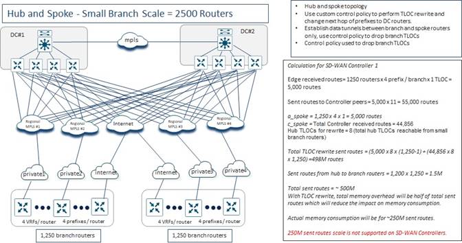
In the Routes Received (RIB-in) Calculations and Scale section of this guide, the number of routes received by each of the SD-WAN Controller instances from the Small Branch routers (SD-WAN Controller 1 through SD-WAN Controller 4) which have OMP peering relationships directly with the SD-WAN Controller instances was calculated. Substituting the numbers from the Small Branch Sites connected to SD-WAN Controller 1 yields the following:
Edge received routes = 1,250 Small Branch routers x
4 IPv4 prefixes sent per Small Branch router
1 TLOC / Small Branch router
= 5,000 IPv4 prefixes / routes
These edge received routes are reflected by SD-WAN Controller 1 to each of the other SD-WAN Controller instances within the overlay. In the example above (and in each Bank of the Earth overlay) there are a total of 12 SD-WAN Controller instances, and therefore SD-WAN Controller 1 has 11 peers.
Hence, the first component of the routes sent (RIB-out) calculation for SD-WAN Controller 1 is as follows:
a x b = (Edge received routes) x (Number of SD-WAN Controller peers to the
given SD-WAN Controller instance)
= 5,000 x 11 = 55,000 routes
We can calculate the second component of routes sent (RIB-out) for SD-WAN Controller 1 as follows:
a_spoke x t x (n_spoke – 1)
where a_spoke = Spoke edge received routes
= (number of spoke / branch routers OMP peered with SD-WAN Controller 1)
X (prefixes per router) x (TLOCs)
= 1,250 x 4 x 1 = 5,000 routes
and t = Number of hub TLOCs through which the spoke edge received routes will be
advertised to be available through
= 8
and n_spoke = number of spoke router peers to SD-WAN Controller 1
= 1,250
a_spoke x t x (n_spoke – 1) = 5,000 x 8 x (1,250 – 1) = 49,960,000 routes
We can calculate the third component of routes sent (RIB-out) for SD-WAN Controller 1 as follows:
a_spoke x n_hub
where a_spoke = Spoke edge received routes
= (number of spoke / branch routers OMP peered with SD-WAN Controller 1)
x (prefixes per router) x (TLOCs)
= 1,250 x 4 x 1 = 5,000 routes
and n_hub = Number of hub routers OMP peered with SD-WAN Controller 1
= 0
a_spoke x n_hub = 5,000 x 0 = 0 routes
We can calculate the fourth component of routes sent (RIB-out) for SD-WAN Controller 1 as follows:
a_hub x n_spoke
where a_hub = Hub edge received routes
= (number of hub routers OMP peered with SD-WAN Controller 1) x
(prefixes per router) x (TLOCs)
= 0 x 0 x 0 = 0
and n_spoke = number of spoke router peers to SD-WAN Controller 1
= 1,250
a_hub x n_spoke = 0 x 1,250 = 0 routes
We can calculate the fifth component of routes sent (RIB-out) for SD-WAN Controller 4 as follows:
c_spoke x t x n_spoke
where c_spoke = number of spoke edge received routes from other SD-WAN Controller
instances
The number of spoke edge receive routes from branch (Small Branch, Medium Branch, and Large/Regional Branch) sites which will be reflected from each of the SD-WAN Controller peers is shown in the following calculations.
Small Branches (SD-WAN Controller 1 through SD-WAN Controller 4)
c_small = (Number of routers not directly connected to the SD-WAN Controller instance)
x (prefixes per router) x (number of TLOCs per router)
= 1,250 x 4 x 1 = 5,000 routes
Medium Branches (SD-WAN Controller 5 through SD-WAN Controller 8)
c_med = (Number of routers not directly connected to the SD-WAN Controller instance) x
(prefixes per router) x (number of TLOCs per router)
= 2,300 x 4 x 2 = 18,400 routes
Large/Regional Branches (SD-WAN Controller 9 through SD-WAN Controller 12)
c_large = (Number of routers not directly connected to the SD-WAN Controller instance)
x (prefixes per router) x (number of TLOCs per router)
= 1,192 x 6 x 3 = 21,456 routes
c_spoke = 5,000 + 18,400 + 21,456 = 44,856 routes
and t = Number of hub / data center TLOCs through which the spoke edge received
routes will be advertised to be available through
= 8
and n_spoke = number of spoke router peers to SD-WAN Controller 1
= 1,250
c_spoke x t x n_spoke = 44,856 x 8 x 1,250 = 448,560,000 routes
We can calculate the sixth component of routes sent (RIB-out) for SD-WAN Controller 1 as follows:
c_spoke x n_hub
where c = number of spoke edge received routes from other SD-WAN Controller instances
= 44,856 routes
and n_hub = number of hub router peers to SD-WAN Controller 1
= 0
c_spoke x n_hub = 44,856 x 0 = 0 routes
Finally, we can calculate the seventh component of routes sent (RIB-out) for SD-WAN Controller 1 as follows:
d x n
where d = number of hub edge received routes from other SD-WAN Controllers
= 1,200 routes
and n = number of router (hub and spoke) peers to the given SD-WAN Controller instance
= 1,250
d x n = 1,200 x 1,250 = 1,500,000 routes
Finally, summarizing the seven components of routes sent gives us the total routes sent (size of the RIB-out table) by SD-WAN Controller 1.
Routes sent by SD-WAN Controller 1 = 55,000 + 49,960,000 + 0 + 0 + 448,560,000 +
0 + 1,500,000
= 500,075,000 routes sent
When using TLOC rewrite policy where prefixes are rewritten to be available via multiple Data Center (Hub) TLOCs, the Cisco Catalyst SD-WAN code has been somewhat optimized to conserve memory. Hence for calculation of memory size, it can typically be assumed that the memory size requirement will be approximately ½ the total number of routes sent. In other words, although, the calculations for routes sent (size of the RIB-out table) for SD-WAN Controller 1 is ~500 M routes, the memory usage within SD-WAN Controller 1 is equivalent to ~250 M routes due to the memory optimizations.
Regardless of the memory optimizations, after consulting with their Cisco account team regarding the maximum routes sent (size of the RIB-out table) supported by SD-WAN Controller instances, Bank of the Earth determined that ~250M routes was beyond Cisco recommendations.
Summary of Branch Site Routes Sent (RIB-out) Calculations – TLOC Rewrite Policy
Bank of the Earth also calculated the routes sent by each of the SD-WAN Controller instances that support the Medium-Sized Branches and the Large / Regional Branches and Data Center Sites, as shown in the following figure.
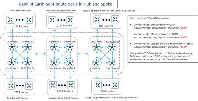
As can be seen, the calculations indicated that with a hub-and-spoke topology implemented through TLOC rewrite policy using only 8 TLOCs for the re-write at the Data Center (Hub) Sites, the number of routes sent (RIB-out) by each SD-WAN Controller instance exceeds Cisco’s recommendations.
Hence, Bank of the Earth concluded that the use of the use of centralized policy to rewrite the TLOC through which branch prefixes are available increases the routes sent (RIB-out) per SD-WAN Controller instance – based on the number TLOCs through which the branch prefixes will be advertised. In the calculations above, Bank of the Earth assumed the use of all 8 TLOCs within the Data Center (Hub) Sites for the rewrite policy. Bank of the Earth could have considered using fewer TLOCs in the rewrite policy to decrease the number of routes sent (RIB-out) per SD-WAN Controller instance, to stay under the maximum routes sent (RIB-out) per SD-WAN Controller instance guidance from Cisco. However, instead, Bank of the Earth decided to look at implementing a hub-and-spoke topology using a default route sent from the Data Center (Hub) sites.
Hub-and-Spoke Topology using Default Route
Bank of the Earth next looked at the calculations for routes sent (RIB-out) when a hub-and-spoke topology was implemented using centralized control policy (applied outbound on the SD-WAN Controller instances) to filter out branch prefixes / routes from being sent to other branch sites (but not the data center sites) and to send a default route from the hub sites along with the hub site prefixes to the branch sites.
In such a hub-and-spoke topology, the routes sent (RIB-out) calculation for each SD-WAN Controller instance consist of the following five components:
● Edge routes received from SD-WAN routers (hub or spoke) that are OMP-peered with the SD-WAN Controller instance, which are then reflected to the other SD-WAN Controller instances within the overlay – since all SD-WAN Controller instances in an overlay are OMP-peered with each other. This can be expressed with the following equation:
a x b
where a = Edge received routes
= (Number of SD-WAN routers with OMP sessions to the SD-WAN Controller) x
(prefixes per router) x (TLOCs)
and b = Number of SD-WAN Controller peers to the given SD-WAN Controller instance
Note that centralized control policy that is used to send a default route from hub sites and filter out spoke prefixes from being sent to other spoke sites is generally applied outbound on SD-WAN Controller instances against the site-IDs of the spoke sites and the hub sites. Since SD-WAN Controller instances are not part of these site-IDs, the policy does not apply to spoke routes sent between SD-WAN Controller instances.
● Edge routes received from spoke SD-WAN routers that are OMP-peered with the SD-WAN Controller instance, which are then reflected to hub SD-WAN routers that are OMP-peered with the same SD-WAN Controller instance. This can be expressed with the following equation:
a_spoke x n_hub
where a_spoke = Spoke edge received routes
= (number of spoke / branch routers OMP peered with the SD-WAN
Controller instance) x (prefixes per router) x (TLOCs)
and n_hub = Number of hub routers OMP peered with the SD-WAN Controller instance
● Edge routes (including the default route) received from hub SD-WAN routers that are OMP-peered with the SD-WAN Controller instance, which are then reflected to spoke SD-WAN routers that are OMP-peered with the same SD-WAN Controller instance. This can be expressed with the following equation:
a_hub x n_spoke
where a_hub = Hub edge received routes
= (number of hub routers OMP peered with the SD-WAN Controller instance) x
(prefixes per router + default route) x (TLOCs)
and n_spoke = number of spoke router peers to the given SD-WAN Controller instance
● Next, we need to account for the spoke edge received routes from other SD-WAN Controller instances in the network which are reflected to the SD-WAN Controller instance and, in turn, reflected to the hub SD-WAN routers OMP-peered with the SD-WAN Controller. This can be expressed with the following equation:
c_spoke x n_hub
where c = number of spoke edge received routes from other SD-WAN Controller instances
and n_hub = number of hub router peers to the given SD-WAN Controller instance
● Finally, we need to account for the hub edge received routes from other SD-WAN Controller instances in the network which are reflected to the SD-WAN Controller instance and, in turn, reflected to the both the spoke SD-WAN routers OMP-peered with the SD-WAN Controller instance. This can be expressed with the following equation:
d x n_spoke
where d = number of hub edge received routes from other SD-WAN Controller instances
and n = number of spoke router peers to the given SD-WAN Controller instance
Note that with this design, the centralized data policy is assumed to filter out prefixes from Data Center (Hub) Sites from being sent to other Data Center (Hub) Sites. Traffic between Data Center (Hub) Sites is assumed to use the MPLS backbone with the Bank of the Earth design, rather than using an SD-WAN tunnel.
Small Branch Site Routes Sent (RIB-out) Calculations – Default Route
The following are the calculations for determining routes sent (RIB-out) for each of the SD-WAN Controller instances dedicated for Small Branch Sites within the Bank of the Earth deployment – assuming a hub-and-spoke deployment with centralized control policy which sends a default route.
In the Routes Received (RIB-in) Calculations and Scale section of this guide, the number of routes received by each of the SD-WAN Controller instances from the Small Branch routers (SD-WAN Controller 1 through SD-WAN Controller 4) which have OMP peering relationships directly with the SD-WAN Controller instances was calculated. Substituting the numbers from the Small Branch Sites connected to SD-WAN Controller 1 yields the following:
Edge received routes = 1,250 Small Branch routers x
4 IPv4 prefixes sent per Small Branch router
1 TLOC / Small Branch router
= 5,000 IPv4 prefixes / routes
These edge received routes are reflected by SD-WAN Controller 1 to each of the other SD-WAN Controller instances within the overlay. In the example above (and in each Bank of the Earth overlay) there are a total of 12 SD-WAN Controller instances, and therefore SD-WAN Controller 1 has 11 peers.
Hence, the first component of the routes sent (RIB-out) calculation for SD-WAN Controller 1 is as follows:
a x b = (Edge received routes) x (Number of SD-WAN Controller peers to the given
SD-WAN Controller instance)
= 5,000 x 11 = 55,000 routes
We can calculate the second component of routes sent (RIB-out) for SD-WAN Controller 1 as follows:
a_spoke x n_hub
where a_spoke = Spoke edge received routes
= (number of spoke / branch routers OMP peered with SD-WAN Controller 1)
x (prefixes per router) x (TLOCs)
= 1,250 x 4 x 1 = 5,000 routes
and n_hub = Number of hub routers OMP peered with SD-WAN Controller 1
= 0
a_spoke x n_hub = 5,000 x 0 = 0 routes
We can calculate the third component of routes sent (RIB-out) for SD-WAN Controller 1 as follows:
a_hub x n_spoke
where a_hub = Hub edge received routes
= (number of hub routers OMP peered with SD-WAN Controller 1) x
(prefixes per router including the default route) x (TLOCs)
= 0 x 0 x 0 = 0
and n_spoke = number of spoke router peers to SD-WAN Controller 1
= 1,250
a_hub x n_spoke = 0 x 1,250 = 0 routes
We can calculate the fourth component of routes sent (RIB-out) for SD-WAN Controller 1 as follows:
c_spoke x n_hub
where c_spoke = number of spoke edge received routes from other SD-WAN Controller
instances
The number of spoke edge receive routes from branch (Small Branch, Medium Branch, and Large/Regional Branch) sites which will be reflected from each of the SD-WAN Controller peers is shown in the following calculations.
Small Branches (SD-WAN Controller 1 through SD-WAN Controller 4)
c_small = (Number of routers not directly connected to the SD-WAN Controller
instance) x (prefixes per router) x (number of TLOCs per router)
= 1,250 x 4 x 1 = 5,000 routes
Medium Branches (SD-WAN Controller 5 through SD-WAN Controller 8)
c_med = (Number of routers not directly connected to the SD-WAN Controller instance) x
(prefixes per router) x (number of TLOCs per router)
= 2,300 x 4 x 2 = 18,400 routes
Large/Regional Branches (SD-WAN Controller 9 through SD-WAN Controller 12)
c_large = (Number of routers not directly connected to the SD-WAN Controller
instance) x (prefixes per router) x (number of TLOCs per router)
= 1,192 x 6 x 3 = 21,456 routes
c_spoke = 5,000 + 18,400 + 21,456 = 44,856 routes
and n_hub = number of hub router peers to SD-WAN Controller 1
= 0
c_spoke x n_hub = 44,856 x 0 = 0 routes
Finally, we can calculate the fifth component of routes sent (RIB-out) for SD-WAN Controller 1 as follows:
d x n_spoke
where d = number of hub edge received routes (including defaults) from other
SD-WAN Controllers
= 31 x 5 x 4 x 2 = 1,240 routes
and n_spoke = number of spoke router peers to SD-WAN Controller 1
= 1,250
d x n_spoke = 1,240 x 1,250 = 1,550,000 routes
Finally, summarizing the five components of routes sent gives us the total routes sent (size of the RIB-out table) by SD-WAN Controller 1.
Routes sent by SD-WAN Controller 1 = 55,000 + 0 + 0 + 0 + 1,550,000
= 1,605,000 or ~1.6M routes sent
With the Bank of the Earth design, SD-WAN Controller 1 through SD-WAN Controller 4 are dedicated to Small Branch sites. Hence each of these SD-WAN Controller instances will have ~1.6M routes sent (RIB-out).
Medium-Sized Branch Site Routes Sent (RIB-out) Calculations – Default Route
The following are the calculations for determining routes sent (RIB-out) for each of the SD-WAN Controller instances dedicated for Medium-Sized Branch Sites within the Bank of the Earth deployment – assuming a hub-and-spoke deployment with centralized control policy which sends a default route.
In the Routes Received (RIB-in) Calculations and Scale section of this guide, the number of routes received by each of the SD-WAN Controller instances from the Medium-Sized Branch routers (SD-WAN Controller 5 through SD-WAN Controller 8) which have OMP peering relationships directly with the SD-WAN Controller instances was calculated. Substituting the numbers from the Medium-Sized Branch Sites connected to SD-WAN Controller 5 yields the following:
Edge received routes = 1,150 Medium-Sized Branch routers x
4 IPv4 prefixes sent per Medium-Sized Branch router
2 TLOCs / Medium-Sized Branch router
= 9,200 IPv4 prefixes / routes
These edge received routes are reflected by SD-WAN Controller 5 to each of the other SD-WAN Controller instances within the overlay. In the example above (and in each Bank of the Earth overlay) there are a total of 12 SD-WAN Controller instances, and therefore SD-WAN Controller 5 has 11 peers.
Hence, the first component of the routes sent (RIB-out) calculation for SD-WAN Controller 5 is as follows:
a x b = (Edge received routes) x (Number of SD-WAN Controller peers to SD-WAN
Controller 5)
= 9,200 x 11 = 101,200 routes
We can calculate the second component of routes sent (RIB-out) for SD-WAN Controller 5 as follows:
a_spoke x n_hub
where a_spoke = Spoke edge received routes
= (number of spoke / branch routers OMP peered with SD-WAN Controller 5)
x (prefixes per router) x (TLOCs)
= 1,150 x 4 x 2 = 9,200 routes
and n_hub = Number of hub routers OMP peered with SD-WAN Controller 5
= 0
a_spoke x n_hub = 9,200 x 0 = 0 routes
We can calculate the third component of routes sent (RIB-out) for SD-WAN Controller 5 as follows:
a_hub x n_spoke
where a_hub = Hub edge received routes
= (number of hub routers OMP peered with SD-WAN Controller 5) x
(prefixes per router including the default route) x (TLOCs)
= 0 x 31 x 8 = 0
and n_spoke = number of spoke router peers to SD-WAN Controller 5
= 1,150
a_hub x n_spoke = 0 x 1,150 = 0 routes
We can calculate the fourth component of routes sent (RIB-out) for SD-WAN Controller 5 as follows:
c_spoke x n_hub
where c_spoke = number of spoke edge received routes from other SD-WAN Controller
instances
The number of spoke edge receive routes from branch (Small Branch, Medium Branch, and Large/Regional Branch) sites which will be reflected from each of the SD-WAN Controller peers is shown in the following calculations.
Small Branches (SD-WAN Controller 1 through SD-WAN Controller 4)
c_small = (Number of routers not directly connected to the SD-WAN Controller instance)
x (prefixes per router) x (number of TLOCs per router)
= 2,500 x 4 x 1 = 10,000 routes
Medium Branches (SD-WAN Controller 7 through SD-WAN Controller 8)
c_med = (Number of routers not directly connected to the SD-WAN Controller instance) x
(prefixes per router) x (number of TLOCs per router)
= 1,150 x 4 x 2 = 9,200 routes
Large/Regional Branches (SD-WAN Controller 9 through SD-WAN Controller 12)
c_large = (Number of routers not directly connected to the SD-WAN Controller instance)
x (prefixes per router) x (number of TLOCs per router)
= 1,192 x 6 x 3 = 21,456 routes
c_spoke = 10,000 + 9,200 + 21,456 = 40,656 routes
and n_hub = number of hub router peers to SD-WAN Controller 5
= 0
c_spoke x n_hub = 40,656 x 0 = 0 routes
Finally, we can calculate the fifth component of routes sent (RIB-out) for SD-WAN Controller 1 as follows:
d x n_spoke
where d = number of hub edge received routes (including defaults) from other SD-WAN
Controllers
= 31 x 5 x 4 x 2 = 1,240 routes
and n_spoke = number of spoke router peers to the given SD-WAN Controller 5 instance
= 1,150
d x n = 1,240 x 1,150 = 1,426,000 routes
Finally, summarizing the five components of routes sent gives us the total routes sent (size of the RIB-out table) by SD-WAN Controller 1.
Routes sent by SD-WAN Controller 1 = 101,200 + 0 + 0 + 0 + 1,426,000
= 1,527,000 or ~1.5M routes sent
With the Bank of the Earth design, SD-WAN Controller 5 through SD-WAN Controller 8 are dedicated to Medium-Sized Branch sites. Hence each of these SD-WAN Controller instances will have ~1.5M routes sent (RIB-out).
Large / Regional Branch & Data Center Site Routes Sent (RIB-out) Calculations – Default Route
Finally, the following are the calculations for determining routes sent (RIB-out) for each of the SD-WAN Controller instances dedicated for Large / Regional Branch and Data Center Sites within the Bank of the Earth deployment – assuming a hub-and-spoke deployment with centralized control policy which sends a default route.
In the Routes Received (RIB-in) Calculations and Scale section of this guide, the number of routes received by each of the SD-WAN Controller instances from the Large / Regional Branch routers (SD-WAN Controller 5 through SD-WAN Controller 8) which have OMP peering relationships directly with the SD-WAN Controller instances was calculated. Substituting the numbers from the Large / Regional Branch sites connected to SD-WAN Controller 9 yields the following:
Edge received routes = (596 Large / Regional Branch routers x
6 IPv4 prefixes sent per Large / Regional Branch router x
3 TLOCs / Large / Regional Branch router) +
(4 Data Center (Hub) routers x
31 IPv4 prefixes sent per Data Center router including default x
5 TLOCs / Data Center router)
= 10,728 + 620 = 11,348 IPv4 prefixes / routes
These edge received routes are reflected by SD-WAN Controller 9 to each of the other SD-WAN Controller instances within the overlay. In the example above (and in each Bank of the Earth overlay) there are a total of 12 SD-WAN Controller instances, and therefore SD-WAN Controller 9 has 11 peers.
Hence, the first component of the routes sent (RIB-out) calculation for SD-WAN Controller 9 is as follows:
a x b = (Edge received routes) x (Number of SD-WAN Controller peers to SD-WAN
Controller 9)
= 11,348 x 11 = 124,828 routes
We can calculate the second component of routes sent (RIB-out) for SD-WAN Controller 9 as follows:
a_spoke x n_hub
where a_spoke = Spoke edge received routes
= (number of spoke / branch routers OMP peered with SD-WAN Controller 9)
x (prefixes per router) x (TLOCs)
= 596 x 6 x 3 = 10,728 routes
and n_hub = Number of hub routers OMP peered with SD-WAN Controller 9
= 4
a_spoke x n_hub = 10,728 x 4 = 42,912 routes
We can calculate the third component of routes sent (RIB-out) for SD-WAN Controller 9 as follows:
a_hub x n_spoke
where a_hub = Hub edge received routes
= (number of hub routers OMP peered with SD-WAN Controller 9) x
(prefixes per router including the default route) x (TLOCs)
= 4 x 31 x 5 = 620
and n_spoke = number of spoke router peers to SD-WAN Controller 9
= 596
a_hub x n_spoke = 620 x 596 = 369,520 routes
We can calculate the fourth component of routes sent (RIB-out) for SD-WAN Controller 9 as follows:
c_spoke x n_hub
where c_spoke = number of spoke edge received routes from other SD-WAN Controller
instances
The number of spoke edge receive routes from branch (Small Branch, Medium Branch, and Large/Regional Branch) sites which will be reflected from each of the SD-WAN Controller peers is shown in the following calculations.
Small Branches (SD-WAN Controller 1 through SD-WAN Controller 4)
c_small = (Number of routers not directly connected to the SD-WAN Controller instance)
x (prefixes per router) x (number of TLOCs per router)
= 2,500 x 4 x 1 = 10,000 routes
Medium Branches (SD-WAN Controller 7 through SD-WAN Controller 8)
c_med = (Number of routers not directly connected to the SD-WAN Controller instance) x
(prefixes per router) x (number of TLOCs per router)
= 2,300 x 4 x 2 = 18,400 routes
Large/Regional Branches (SD-WAN Controller 11 through SD-WAN Controller 12)
c_large = (Number of routers not directly connected to the SD-WAN Controller instance)
x (prefixes per router) x (number of TLOCs per router)
= 596 x 6 x 3 = 10,728 routes
c_spoke = 10,000 + 18,400 + 10,728 = 39,128 routes
and n_hub = number of hub router peers to SD-WAN Controller 9
= 4
c_spoke x n_hub = 39,128 x 4 = 156,512 routes
Finally, we can calculate the fifth component of routes sent (RIB-out) for SD-WAN Controller 9 as follows:
d x n_spoke
where d = number of hub edge received routes (including defaults) from other SD-WAN
Controllers
= 31 x 5 x 4 = 620 routes
and n_spoke = number of spoke router peers to SD-WAN Controller 9
= 596
d x n = 620 x 596 = 369,520 routes
Finally, summarizing the five components of routes sent gives us the total routes sent (size of the RIB-out table) by SD-WAN Controller 9.
Routes sent by SD-WAN Controller 1 = 124,828 + 42,912 + 369,520 + 156,512 + 369,520
= 1,063,292 or ~1M routes sent
Summary of Branch Site Routes Sent (RIB-out) Calculations – Default Route
The following figure summarizes Bank of the Earth’s calculations for the routes sent by each of the SD-WAN Controller instances that support the Small Branches, Medium-Sized Branches and the Large / Regional Branches when a hub-and-spoke data plane topology is implemented using a centralized control policy which filters branch prefixes / routes from being sent to other branch sites and sends a default route from the data center hub sites (along with the data center prefixes).
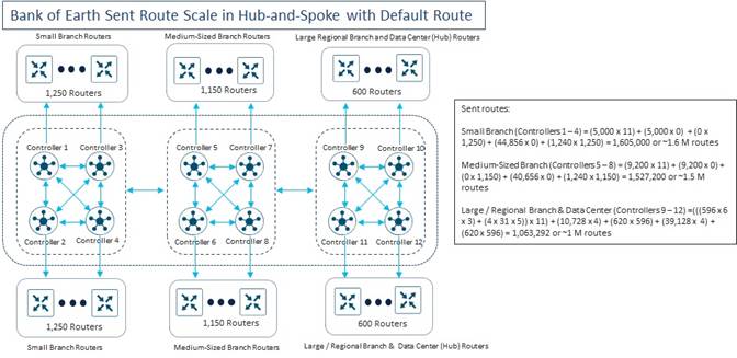
As can be seen, the calculations indicated that with a hub-and-spoke topology implemented through sending a default route rather than through TLOC rewrite policy, the number of routes sent (RIB-out) of all the SD-WAN Controller instances within the Bank of the Earth overlay was significantly reduced and well within Cisco’s recommendations.
| Technical Note: |
| The final design of the Bank of Earth network includes tunnel group configurations, which will not change the OMP route calculations for the SD-WAN Controller instances. Also, the total number of routes received (RIB-in) and routes sent (RIB-out) will remain the same with the tunnel group configuration. |
Bank of the Earth Hybrid Design
As mentioned previously, the two methods for implementing a hub-and-spoke fabric data plane topology – TLOC rewrite policy and default route policy – are not mutually exclusive within an overlay. The following presents an example of how that could be done.
| Technical Note: |
| This section is included primarily for illustrative purposes to demonstrate how multiple methods can simultaneously be used to implement a hub-and-spoke fabric data plane topology within a large SD-WAN deployment. In most production deployments, typically the organization will choose one method – either a centralized control policy using TLOC rewriting of the branch prefixes to the hub site TLOCs, or a centralized control policy which sends a default route from the hub sites and filters out branch routes and TLOCs from being sent to each other. |
With the Bank of the Earth hybrid design, centralized control policy is used to send a default route (along with the other routes / prefixes located within the Data Center sites) from the Data Center (Hub) routers to the Small Branch and Medium-Sized Branch routers. Small Branch and Medium-Sized Branch prefixes / routes and TLOCs are sent to the Data Center (Hub) routers. Outbound control policy applied to the Small Branch and Medium-Sized Branch sites filters these prefixes / routes and TLOCs from being sent to each other. The Data Center (Hub) routers require the Small Branch and Medium-Sized Branch prefixes / routes and TLOCs to know how to send traffic back to the correct branch.
Small Branch and Medium-Sized Branch routes / prefixes are also sent to Large / Regional Branch sites. However, outbound centralized control policy applied to the Large / Regional Branch sites is used to rewrite the TLOC through which the Small Branch and Medium-Sized Branch routes / prefixes are available. All 8 Data Center (Hub) router TLOCs are used for the TLOC rewrite policy for the Large / Regional Branch sites.
In addition to this, Bank of the Earth set the TLOC preference within the outbound centralized control policy, such that the routes advertised from the western data center (Data Center #1) were preferred by the branch sites located within the western side of the overlay. Likewise, the routes advertised from the eastern data center (Data Center #2) were preferred by the branch sites located within the eastern side of the overlay. Note that this means that any traffic originating from a branch site on the western side of the overlay destined for a server within the data center in the eastern side of the overlay would have to traverse the global MPLS backbone. However, this was an acceptable design for Bank of the Earth.
The following figures provide a very simplified high-level example of how such a centralized control policy could be constructed.
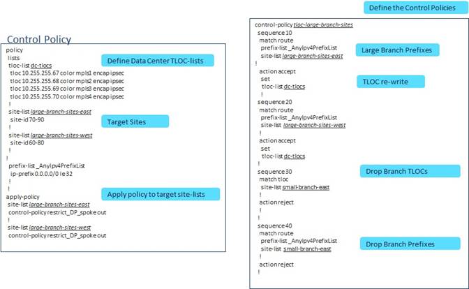
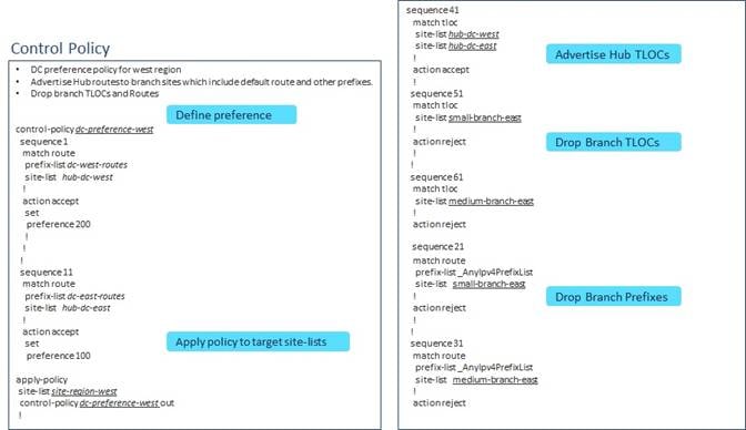
Bank of the Earth also realized that a hybrid design would change the routes sent (RIB-out) calculations – specifically for the SD-WAN Controller instances dedicated to the Large / Regional Branch and Data Center sites. Using the knowledge they gained from the exercise of calculating routes sent (RIB-out) for hub-and-spoke designs using TLOC rewrite policy and using a default route policy, they estimated the routes sent (RIB-out) for each of the SD-WAN Controller instances as shown in the following figure.
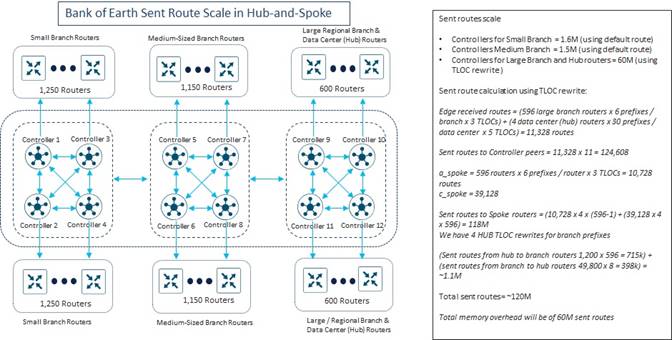
After discussing the routes sent (RIB-out) scale (specifically for the SD-WAN Controller instances dedicated for Large / Regional Branch and Data Center (Hub) sites) with their Cisco account team, Bank of the Earth determined that the estimates were within Cisco recommendations for maximum routes sent (RIB-out) for individual SD-WAN Controller instances.
SD-WAN Controller Server Layout and IP Addressing
The following figure shows the general layout of a data center within one of Bank of the Earth’s SD-WAN overlays, with the placement of the controllers for the SD-WAN implementation.
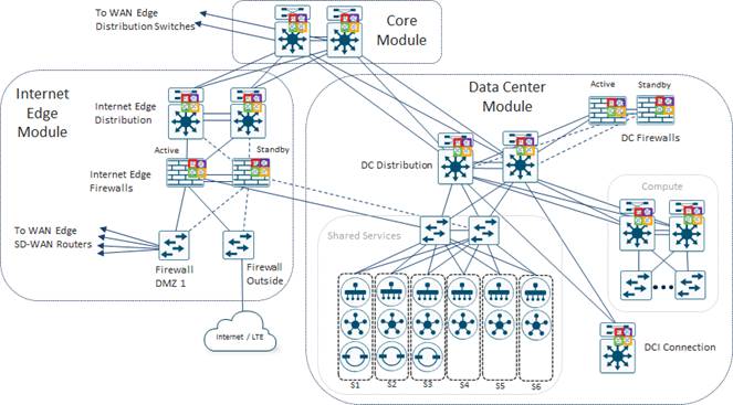
As shown in the figure above, the design requires 6 servers for the primary SD-WAN Manager cluster within the first data center. An additional 6 servers are deployed for the backup SD-WAN Manager cluster in the second data center (not shown).
Bank of the Earth followed the guidance of their Cisco account team and implemented the server configuration referenced in the testbed specifications for UCS platforms within the Recommended Computing Resources for Cisco Catalyst SD-WAN Control Components Release 20.9.x chapter of the Cisco Catalyst SD-WAN Control Components Compatibility Matrix and Recommended Computing Resources documentation found at the following URL:
https://www.cisco.com/c/en/us/td/docs/routers/sdwan/release/notes/compatibility-and-server-recommendations/ch-server-recs-20-9-combined.html
The following table shows the controller instances running on each of the 6 servers within each data center for each of the overlays.
Table 6. Controller Instances Running per Server in Each Overlay
|
|
UCS 1 |
UCS 2 |
UCS 3 |
UCS4 |
UCS 5 |
UCS 6 |
| Overlay |
1 SD-WAN Manager 1 SD-WAN Validator 1 SD-WAN Controller |
1 SD-WAN Manager 1 SD-WAN Validator 1 SD-WAN Controller |
1 SD-WAN Manager 1 SD-WAN Validator 1 SD-WAN Controller |
1 SD-WAN Manager 1 SD-WAN Controller |
1 SD-WAN Manager 1 SD-WAN Controller |
1 SD-WAN Manager 1 SD-WAN Controller |
Each physical server runs a single instance of the SD-WAN Manager. Co-hosting multiple SD-WAN Manager instances a on single server is not supported. However, co-hosting SD-WAN Controller and/or SD-WAN Validator instances with a SD-WAN Manager instance is supported, provided sufficient resources (CPU, RAM, and Storage/Disk Space) are available on the server.
The Cisco UCS servers were configured for 1:1 virtual CPU (vCPU) to physical CPU (pCPU), per Cisco’s guidance found within the Points to Consider chapter of the Cisco Catalyst SD-WAN Control Components Compatibility Matrix and Recommended Computing Resources following document:
The following figure shows details for the connectivity of the servers within the data center.
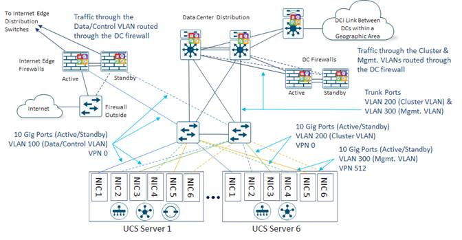
SD-WAN Manager instances require three separate Ethernet connections to three separate VLANs as follows:
● Data/Control Connection. This is the Ethernet port / VLAN through which all DTLS / TLS control connections between the SD-WAN Manager servers, SD-WAN routers, SD-WAN Controllers, and SD-WAN Validators flows.
● Cluster Connection. This is the Ethernet port / VLAN through which all SD-WAN Manager intra-cluster traffic, such as database synchronization / replication, flows. It is also the port through which inter-cluster database replication occurs when deploying a secondary SD-WAN Manager cluster for disaster recovery.
● Management Port Connection. This is the Ethernet port / VLAN through which management (both end-user and north-bound REST API) access to the SD-WAN Manager instance(s) is established. This maps to Service VPN 512 on the SD-WAN control components.
The design chosen by Bank of the Earth for link-level resiliency is the more traditional active / standby design using multiple VLANs. During normal operations one Layer-2 switch is the active switch for data/control (VLAN 100) and management (VLAN 300) connectivity to the SD-WAN Manager instances, and the standby switch for cluster (VLAN 200) connectivity.
SD-WAN Validator and SD-WAN Controller instances only require two Ethernet connections / VLANs as follows:
● Data/Control Connection. This is the Ethernet port / VLAN through which all DTLS / TLS control connections between the SD-WAN Manager servers, SD-WAN routers, SD-WAN Controllers, and SD-WAN Validators flows.
● Management Port Connection. This is the Ethernet port / VLAN through which out-of-band management access to the SD-WAN Validator or SD-WAN Controller instance(s) is established.
For the Bank of the Earth deployment the same UCS server NICs and same Layer 2 switch ports are used for the data/control and management connections for the SD-WAN Manager, SD-WAN Controller, and SD-WAN Validator instances within each UCS server. Bank of the Earth uses 10 Gbps Ethernet ports for all server connections to the Layer 2 switches.
The attachment of an active / standby data center firewall pair to the data center aggregation switches allows Bank of the Earth to direct traffic destined for the SD-WAN controller instances through the firewall. The management VLAN (VLAN 300) and the cluster VLAN (VLAN 200) are trunked from the Layer 2 access-layer switches to the Layer 3 data center aggregation switches. From there, the cluster VLAN (VLAN 200) traffic is routed across through the DCI link between data centers via the Layer 3 DCI router within the data center. Optionally, Bank of the Earth could choose to trunk the cluster VLAN (VLAN 200) traffic to the data center firewall pair before routing it back through the data center aggregation switches and to the DCI router. The management VLAN (VLAN 300) is trunked through the data center aggregation switch to the data center firewalls. Access control into the management VLAN (VLAN 300) – meaning HTTPS and SSH access to the management interfaces of the SD-WAN control components – is controlled by policy on the data center firewall pair.
The data/control VAN (VLAN 100) is not trunked to the data center aggregation switch in the Bank of the Earth design. Instead, the data/control VLAN is connected to the Internet Edge firewall pair. This is because the SD-WAN routers within the overlay need to establish DTLS control connections to the SD-WAN Validator instances, as well as DTLS/TLS control connections to the SD-WAN Controller and SD-WAN Manager instances via the data/control VLAN (VLAN 100). The SD-WAN routers need to form these control connections via their Internet-facing (biz-internet) TLOCs as well as their MPLS-facing (private1 – private6) TLOCs. This choice was made along with the decision to use public IP addressing for the data/control connections on the SD-WAN Validator, SD-WAN Controller, and SD-WAN Manager instances to simplify the design and minimize the use of NAT – particularly the user of source and destination NAT which causes traffic to hairpin through a firewall – for reachability to the SD-WAN control components.
SD-WAN Controller IP Addressing
Bank of the Earth evaluated various designs for using public versus private (RFC 1918) IP addressing of the data/control interfaces of their on-prem SD-WAN control components; as well as for connecting the data/control interfaces of the SD-WAN control components via the data center firewall pair or the Internet Edge firewall pair. Each are discussed briefly below.
Option #1: Data/control Interfaces Connected to the Data Center Firewalls with RFC-1918 Addressing
An example of this design (which has been simplified for this discussion) is shown in the figure below.
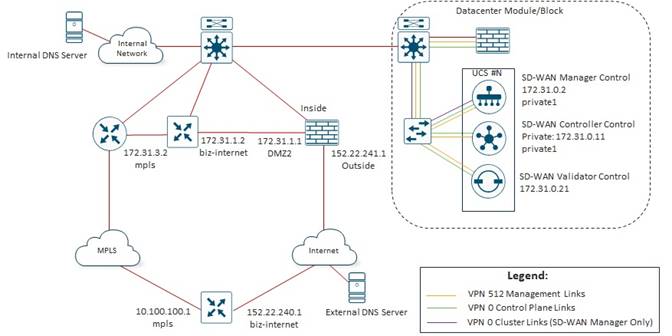
With this option, the data/control, management, and cluster (SD-WAN Manager only) connections of the SD-WAN control components are trunked from the Layer 2 access-switches to the Layer 3 data center aggregation switches. The data/control and management VLANs are further trunked through the Layer 3 data center aggregation switches to the data center firewall pair. The cluster VLAN bypasses the data center firewalls, routing traffic directly over the DCI link between data centers. Optionally, the cluster VLAN can be trunked to the data center firewall pair as well if desired. Access to the management interfaces of the SD-WAN control components is therefore controlled by the data center firewalls, and all traffic to the data/control interfaces of the SD-WAN control components must also pass through the data center firewalls.
When SD-WAN Manager and SD-WAN Controller instances establish DTLS control connections to the SD-WAN Validator instances, they must do so using their public IP addresses. This is necessary for the Bank of the Earth design, since they have Internet-facing TLOCs on both the branch and data center SD-WAN routers. These Internet-facing TLOCs will only be able to reach the public IP addresses of the SD-WAN control components. After forming temporary DTLS control connections to the SD-WAN Validator instances, the SD-WAN Validator instances inform the SD-WAN routers of the IP addresses of the SD-WAN Manager and SD-WAN Controller instances. Hence the SD-WAN Validators must be aware of the public IP addresses of the SD-WAN Manager and SD-WAN Controller instances. Only then will the SD-WAN routers be able to form permanent DTLS/TLS control connections to the SD-WAN Controller and SD-WAN Manager instances within the data center. For this option, the public IP addresses of the SD-WAN control components are provided through static source and destination NAT translations at the Internet Edge firewall pair, using IP addresses which are part of the same public IP subnet as the Outside interface of the Internet Edge firewall.
However, implementing static source and destination NAT at the Internet Edge firewall results in somewhat complex hair-pinning of traffic at the Internet Edge firewall when the SD-WAN Manager or SD-WAN Controller instances form DTLS control connections to the SD-WAN Validator instances, as shown in the following figure.
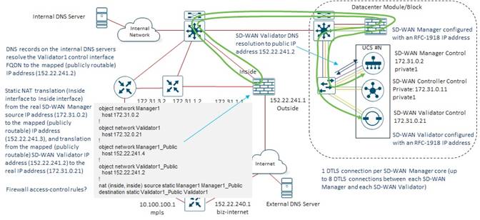
Bank of the Earth wanted to avoid the complexity of hair-pinning the DTLS control connections between the SD-WAN Manager and SD-WAN Controller instances to the SD-WAN Validator instances through the Internet Edge firewall pair, and therefore looked for an alternative option.
Option #2: Data/control Interfaces Connected to the Internet Edge Firewalls with RFC-1918 Addressing
For the second option, Bank of the Earth considered moving the data/control interface of the SD-WAN control components from the data center firewalls to the Internet Edge firewalls, still using RFC-1918 addressing. An example of this design is shown in the figure below.
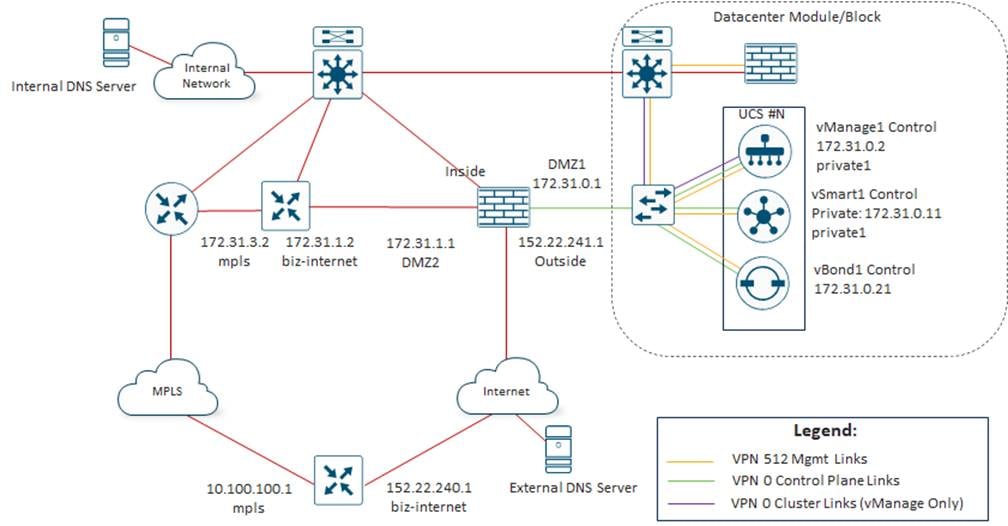
With this option, only the management and cluster (SD-WAN Manager only) connections of the SD-WAN control components are trunked from the Layer 2 access-switches to the Layer 3 data center aggregation switches. The management VLAN is further trunked through the Layer 3 data center aggregation switches to the data center firewall pair. The cluster VLAN bypasses the data center firewalls, routing traffic directly over the DCI link between data centers. Optionally, the cluster VLAN can be trunked to the data center firewall pair as well if desired. Access to the management interfaces of the SD-WAN control components is therefore still controlled by the data center firewalls, but traffic to the data/control interfaces of the SD-WAN control components no longer passes through the data center firewalls.
As shown in the following figure, this option somewhat simplifies, but does not eliminate the hair-pinning of traffic at the Internet Edge firewall due to the use of source and destination NAT, when the SD-WAN Manager or SD-WAN Controller instances form DTLS control connections to the SD-WAN Validator instances.
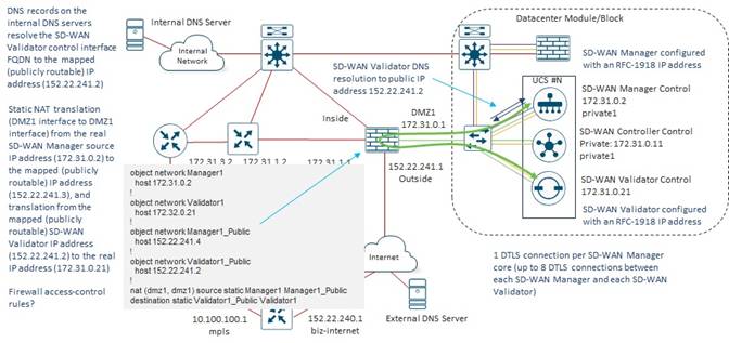
Bank of the Earth considered this to be a viable option for both the connectivity of the data/control interfaces and the IP addressing of the SD-WAN control components. However, they continued to look for a simpler option that eliminated the need for any hair-pinning of traffic at the Internet Edge firewall due to the use of private (RFC 1918) addressing of the data/control interfaces of the SD-WAN control components.
Option #3: Data/control Interfaces Connected to the Data Center Firewalls with Public IP Addressing
For the third option, the data/control, management, and cluster (SD-WAN Manager only) connections of the SD-WAN control components are again trunked from the Layer 2 access-switches to the Layer 3 data center aggregation switches. The data/control and management VLANs are further trunked through the Layer 3 data center aggregation switches to the data center firewall pair. The cluster VLAN bypasses the data center firewalls, routing traffic directly over the DCI link between data centers. Optionally, the cluster VLAN can be trunked to the data center firewall pair as well if desired. Access to the management interfaces of the SD-WAN control components is therefore controlled by the data center firewalls, and all traffic to the data/control interfaces of the SD-WAN control components must also pass through the data center firewalls. However, public IP addressing is used for the data/control interfaces of the SD-WAN control components. An example of this design is shown in the figure below.
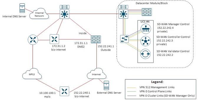
The use of public IP addressing for the data/control interfaces of the SD-WAN control components removes the need for NAT to be configured on the Internet Edge firewall. However, it does require Bank of the Earth to procure an additional public IP subnet, separate from the public IP subnet used for the Outside interface of the Internet Edge firewall pair, from their Internet Service Provider at each data center. Further, the public IP subnet address space needs to be routed through the underlay, so that the MPLS-facing TLOCs of the SD-WAN routers at the branch and head-end locations can establish control connections to the SD-WAN Validator, SD-WAN Controller, and SD-WAN Manager instances within each of the Bank of the Earth data centers. This public IP subnet for the data/control interfaces of the SD-WAN control components represents an additional cost for the simplicity of not needing to configure static source and destination NAT translations on their Internet Edge firewalls.
Bank of the Earth recognized that access-control to the data/control interfaces of the SD-WAN control components would be split between the data center and Internet Edge firewalls with this option. As can be seen in the following figure, when an Internet-facing TLOC of a branch SD-WAN router establishes control connections to the SD-WAN control components within the data center, the traffic passes through both the Internet Edge firewall pair and the data center firewall pair.
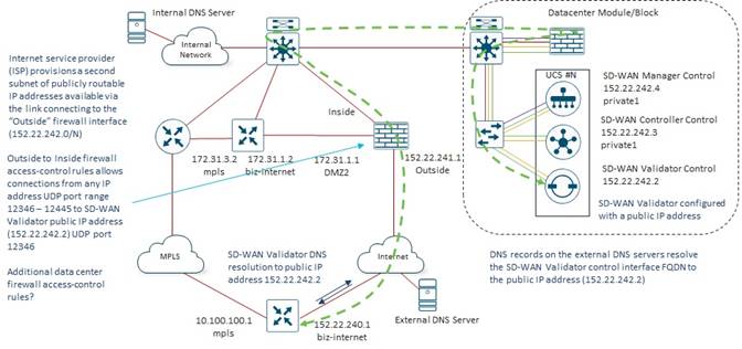
However, when an MPLS-facing TLOC of a branch SD-WAN router establishes control connections to the SD-WAN control components within the data center, the traffic passes through the data center firewall pair only.
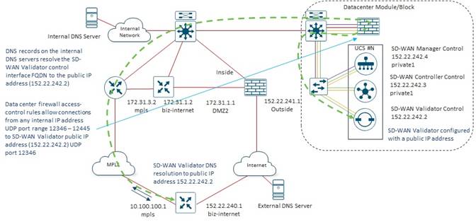
Although some would consider this to be an example of “defense in depth” – meaning that there are multiple points where control of connectivity to the Data/Control interface of the SD-WAN control components are enforced – Bank of the Earth viewed splitting the access-control between the Data Center firewall pair and the Internet Edge firewall pair as an opportunity for configuration mistakes to be made. Again, although Bank of the Earth considered this option to be viable, they opted for a simpler solution where all access control was configured at a single point – the Internet Edge firewall pair.
Option #4: Data/Control Interfaces Connected to the Internet Edge Firewalls with Public IP Addressing
For the fourth option, Bank of the Earth again considered moving the data/control interface of the SD-WAN control components from the data center firewalls to the Internet Edge firewalls, this time using public IP addressing. An example of this design is shown in the figure below.
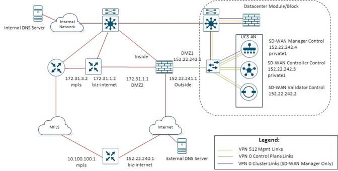
With this option, only the management and cluster (SD-WAN Manager only) connections of the SD-WAN control components are again trunked from the Layer 2 access-switches to the Layer 3 data center aggregation switches. The management VLAN is further trunked through the Layer 3 data center aggregation switches to the data center firewall pair. The cluster VLAN bypasses the data center firewalls, routing traffic directly over the DCI link between data centers. Optionally, the cluster VLAN can be trunked to the data center firewall pair as well if desired. Access to the management interfaces of the SD-WAN control components is therefore still controlled by the data center firewalls, but traffic to the data/control interfaces of the SD-WAN control components no longer passes through the data center firewalls.
Because public IP addressing is used for the data/control connections of the SD-WAN control components, the SD-WAN control components can directly reach each other to form control-plane connections between themselves, without having to do any translations from RFC 1918 addressing to public IP addressing. Hence, there is no hair-pinning of traffic due to the configuration of source-destination NAT at the Internet Edge firewall.
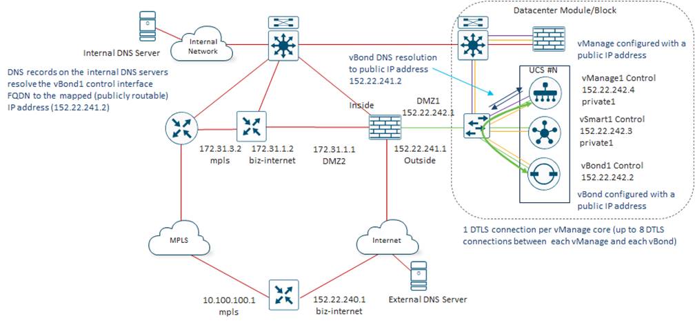
As with Option #2, the use of public IP addressing for the data/control interfaces of the SD-WAN control components requires Bank of the Earth to procure an additional public IP subnet, separate from the public IP subnet used for the Outside interface of the Internet Edge firewall pair, from their Internet Service Provider (ISP) at each data center. Further, the public IP subnet address space needs to be routed through the underlay, so that the MPLS-facing TLOCs of the SD-WAN routers at the branch and head-end sites can establish control connections to the SD-WAN Validator, SD-WAN Controller, and SD-WAN Manager instances within each of the Bank of the Earth data centers. This public IP subnet for the data/control interfaces of the SD-WAN control components represents an additional cost for the simplicity of not needing to configure static source and destination NAT translations on their Internet Edge firewalls.
To ensure there were no apparent issues with this option for connectivity of the data/control interfaces of the on-prem SD-WAN control components, as well as the IP addressing, Bank of the Earth needed to walk through how SD-WAN routers at both the branch and head-end sites would form control-plane connections and data-plane tunnels.
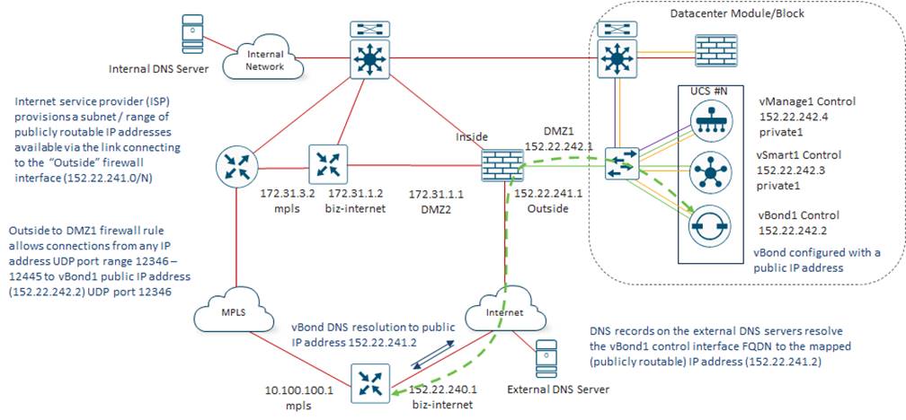
For the Internet-facing TLOCs of the branch SD-WAN routers, the SD-WAN Validator public IP addresses are resolved via external DNS servers, reachable via the Internet. The SD-WAN Validator public IP addresses are reachable through the Outside interface of the Internet Edge firewall of each data center, as provisioned by the Internet Service Provider (ISP). An Outside-to-DMZ1 firewall rule applied inbound on the Outside interface of the Internet Edge firewall restricts inbound connections sourced from any IP address to the UDP port range 12346 – 12445 of each of the destination public IP addresses of the SD-WAN Validator instances within each respective data center.
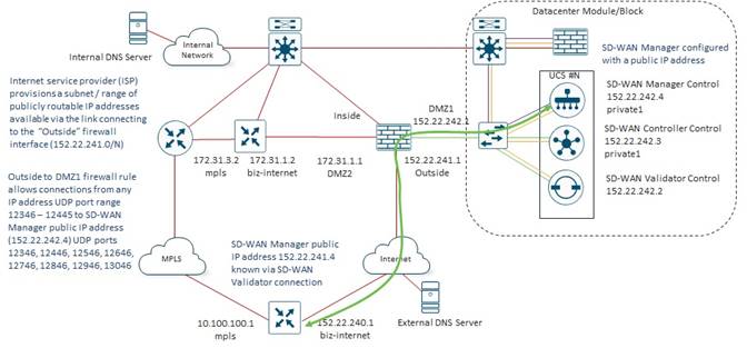
Once the transient SD-WAN Validator connections have been established, the Internet-facing TLOCs of the branch SD-WAN routers learn the public IP addresses of the SD-WAN Controller instances within each respective data center. Again, these IP addresses are reachable through the Outside interface of the Internet Edge firewall of each data center, as provisioned by the Internet Service Provider (ISP). An Outside-to-DMZ1 firewall rule applied inbound on the Outside interface of the Internet Edge firewall restricts inbound connections sourced from any IP address with the source UDP port range 12346 – 12445 to the specific destination UDP ports of each of the destination public IP addresses of the SD-WAN Controller instances within each respective data center.
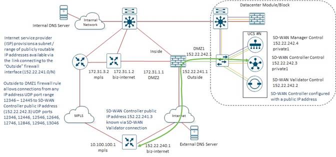
Likewise, the Internet-facing TLOCs of the branch SD-WAN routers learn the public IP addresses of the SD-WAN Manager instances within each respective data center from the SD-WAN Validator instances. Again, these IP addresses are reachable through the Outside interface of the Internet Edge firewall of each data center, as provisioned by the Internet Service Provider (ISP). An Outside-to-DMZ1 firewall rule applied inbound on the Outside interface of the Internet Edge firewall restricts inbound connections sourced from any IP address with the source UDP port range 12346 – 12445 to the specific destination UDP ports of each of the destination public IP addresses of the SD-WAN Manager instances within each respective data center.
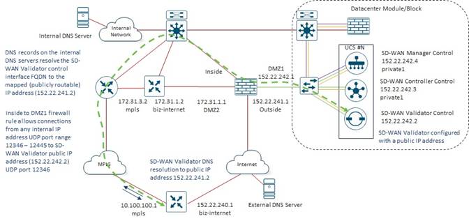
For the MPLS-facing TLOCs of the branch SD-WAN routers, the SD-WAN Validator public IP addresses are resolved via internal DNS servers, reachable via the MPLS underlay. The SD-WAN Validator public IP addresses are reachable through the Inside interface of the Internet Edge firewall of each data center, since the public IP addressing of the SD-WAN control components is routed through the MPLS underlay. An Inside-to-DMZ1 firewall rule applied inbound on the Inside interface of the Internet Edge firewall restricts inbound connections sourced from any internal IP address to the UDP port range 12346 – 12445 of each of the destination public IP addresses of the SD-WAN Validator instances within each respective data center.
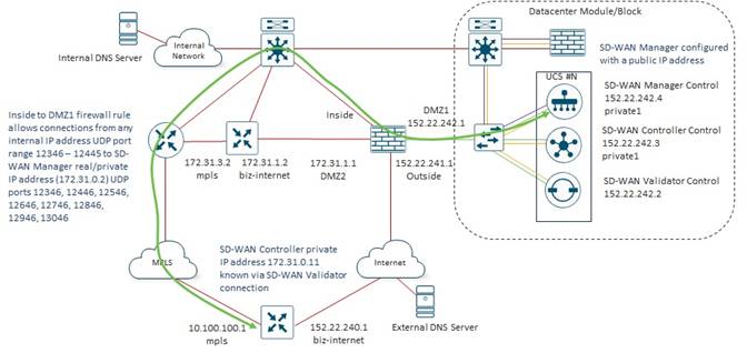
Once the transient SD-WAN Validator connections have been established, the MPLS-facing TLOCs of the branch SD-WAN routers learn the public IP addresses of the SD-WAN Controller instances within each respective data center. Again, these IP addresses are reachable through the Inside interface of the Internet Edge firewall of each data center, since the public IP addressing of the SD-WAN control components is routed through the MPLS underlay. An Inside-to-DMZ1 firewall rule applied inbound on the Inside interface of the Internet Edge firewall restricts inbound connections sourced from any internal IP address with the source UDP port range 12346 – 12445 to the specific destination UDP ports of each of the destination public IP addresses of the SD-WAN Controller instances within each respective data center.
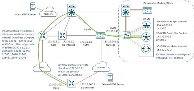
Likewise, the MPLS-facing TLOCs of the branch SD-WAN routers learn the public IP addresses of the SD-WAN Manager instances within each respective data center from the SD-WAN Validator instances. Again, these IP addresses are reachable through the Inside interface of the Internet Edge firewall of each data center, since the public IP addressing of the SD-WAN control components is routed through the MPLS underlay. An Inside-to-DMZ1 firewall rule applied inbound on the Inside interface of the Internet Edge firewall restricts inbound connections sourced from any internal IP address with the source UDP port range 12346 – 12445 to the specific destination UDP ports of each of the destination public IP addresses of the SD-WAN Manager instances within each respective data center.
For the head-end SD-WAN routers, Bank of the Earth decided to use private (RFC-1918) IP addressing for the Internet-facing WAN interfaces. They configured 1:1 static NAT entries on the Internet Edge firewall, mapping IP addresses from the same IP subnet as the Outside interface of the Internet Edge firewall to the private (RFC-1918) IP addresses of the head-end SD-WAN routers within each data center. Because of this, they did not have to procure a third public IP subnet range from their Internet Service Provider (ISP). Since there are four head-end SD-WAN routers within each data center, four additional public IP addresses were required from the same subnet as the Outside interface if the Internet Edge firewall within each data center.
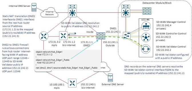
For the Internet-facing TLOCs of the head-end SD-WAN routers, the SD-WAN Validator public IP addresses are resolved via external DNS servers, reachable via the Internet. The SD-WAN Validator public IP addresses are reachable through the DMZ2 interface of the Internet Edge firewall of each data center since the default route of the Internet-facing interfaces of the SD-WAN head-end routers points to the DMZ2 interface of the Internet-Edge firewall. A DMZ2-to-DMZ1 firewall rule applied inbound on the DMZ2 interface of the Internet Edge firewall restricts inbound connections sourced from the specific IP addresses of the head-end SD-WAN routers to the UDP port range 12346 – 12445 of each of the destination public IP addresses of the SD-WAN Validator instances within each respective data center.
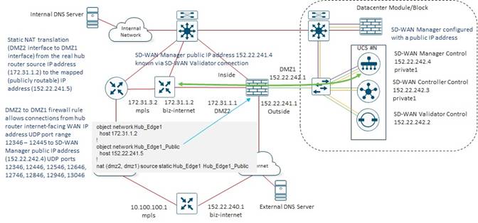
Once the transient SD-WAN Validator connections have been established, the Internet-facing TLOCs of the head-end SD-WAN routers learn the public IP addresses of the SD-WAN Controller instances within each respective data center. Again, these IP addresses are reachable through the DMZ2 interface of the Internet Edge firewall of each data center. A DMZ2-to-DMZ1 firewall rule applied inbound on the DMZ2 interface of the Internet Edge firewall restricts inbound connections sourced from the specific IP addresses of the head-end SD-WAN routers with the source UDP port range 12346 – 12445 to the specific destination UDP ports of each of the destination public IP addresses of the SD-WAN Controller instances within each respective data center.
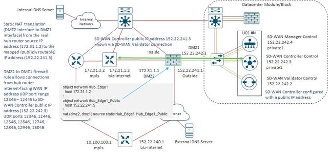
Likewise, the Internet-facing TLOCs of the head-end SD-WAN routers learn the public IP addresses of the SD-WAN Manager instances within each respective data center from the SD-WAN Validator instances. Again, these IP addresses are reachable through the DMZ2 interface of the Internet Edge firewall of each data center. A DMZ2-to-DMZ1 firewall rule applied inbound on the DMZ2 interface of the Internet Edge firewall restricts inbound connections sourced from the IP addresses of the head-end SD-WAN routers with the source UDP port range 12346 – 12445 to the specific destination UDP ports of each of the destination public IP addresses of the SD-WAN Manager instances within each respective data center.
The MPLS-facing interfaces of the head-end routers are nearly identical to the MPLS-facing interfaces of the branch routers, from the perspective of establishing control connections to the SD-WAN routers within each data center.
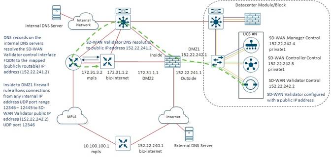
For the MPLS-facing TLOCs of the head-end SD-WAN routers, the SD-WAN Validator public IP addresses are resolved via internal DNS servers, reachable via the MPLS underlay. The SD-WAN Validator public IP addresses are reachable through the Inside interface of the Internet Edge firewall of each data center, since the public IP addressing of the SD-WAN control components is routed through the MPLS underlay. An Inside-to-DMZ1 firewall rule applied inbound on the Inside interface of the Internet Edge firewall restricts inbound connections sourced from any internal IP address to the UDP port range 12346 – 12445 of each of the destination public IP addresses of the SD-WAN Validator instances within each respective data center.
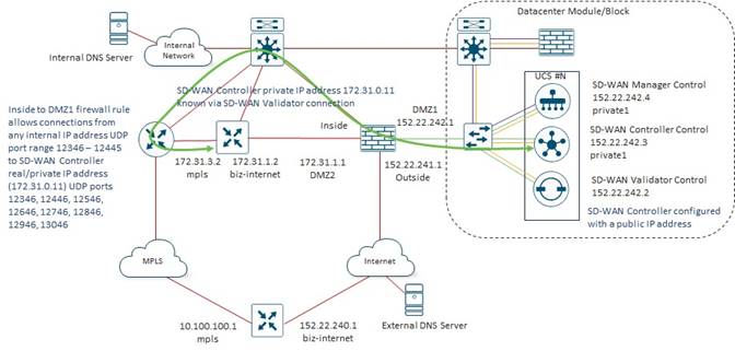
Once the transient SD-WAN Validator connections have been established, the MPLS-facing TLOCs of the head-end SD-WAN routers learn the public IP addresses of the SD-WAN Controller instances within each respective data center. Again, these IP addresses are reachable through the Inside interface of the Internet Edge firewall of each data center, since the public IP addressing of the SD-WAN control components is routed through the MPLS underlay. An Inside-to-DMZ1 firewall rule applied inbound on the Inside interface of the Internet Edge firewall restricts inbound connections sourced from any internal IP address with the source UDP port range 12346 – 12445 to the specific destination UDP ports of each of the destination public IP addresses of the SD-WAN Controller instances within each respective data center.
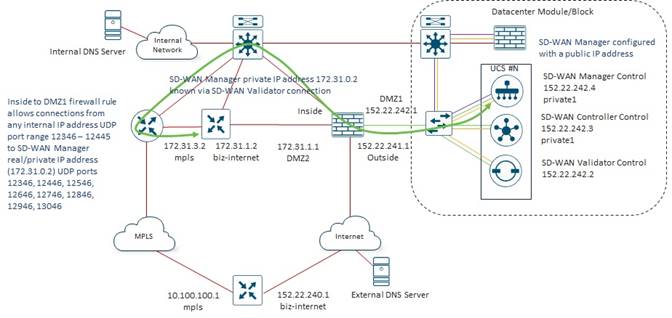
Likewise, the MPLS-facing TLOCs of the head-end SD-WAN routers learn the public IP addresses of the SD-WAN Manager instances within each respective data center from the SD-WAN Validator instances. Again, these IP addresses are reachable through the Inside interface of the Internet Edge firewall of each data center, since the public IP addressing of the SD-WAN control components is routed through the MPLS underlay. An Inside-to-DMZ1 firewall rule applied inbound on the Inside interface of the Internet Edge firewall restricts inbound connections sourced from any internal IP address with the source UDP port range 12346 – 12445 to the specific destination UDP ports of each of the destination public IP addresses of the SD-WAN Manager instances within each respective data center.
It should be noted that control connections are formed from head-end SD-WAN routers in one data center to SD-WAN control components in the other data center. These have not been shown within the figures above. Since the public IP addresses of the SD-WAN control components within each data center are routed across the underlay, regardless of which data center the head-end SD-WAN routers are located within, and regardless of which data center the SD-WAN control components are located within, reachability exists, allowing the control connections to be formed.
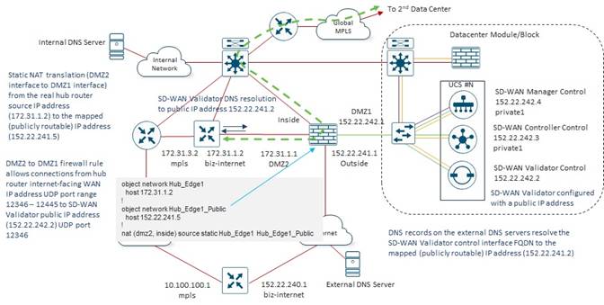
Finally, once the control-plane connections between the branch and head-end SD-WAN routers are formed, the data-plane connections can be formed.
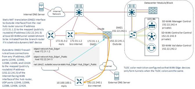
The Internet-facing TLOCs of the branch SD-WAN routers learn the public IP addresses of the head-end routers via OMP routes sent from the SD-WAN Controllers. These IP addresses are reachable through the Outside interface of the Internet Edge firewall of each data center, as provisioned by the Internet Service Provider (ISP). An Outside-to-DMZ2 firewall rule applied inbound on the Outside interface of the Internet Edge firewall restricts inbound connections sourced from any IP address with the specific UDP port range to the destination public IP addresses and specific UDP port range of the head-end SWAN routers within each respective data center.
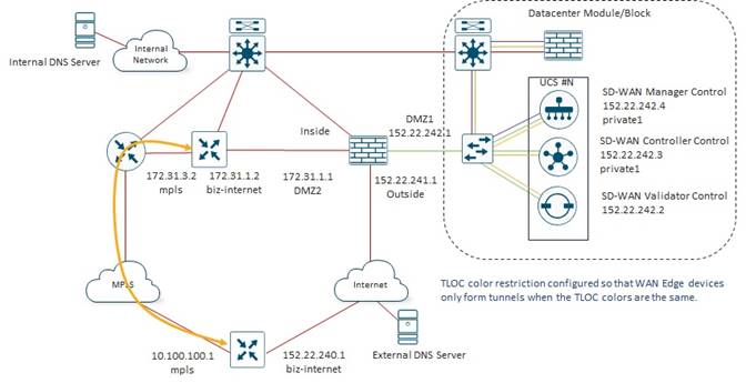
The MPLS-facing TLOCs of the branch SD-WAN routers also learn the private (RFC-1918) IP addresses of the head-end routers via OMP routes sent from the SD-WAN Controllers. These IP addresses are directly reachable through the respective MPLS carrier network.
Bank of the Earth does not currently provide Direct Internet Access (DIA) from branch locations – either for the Internal Employee VLAN or the Guest Wi-Fi VLAN. All traffic is backhauled through one of the data centers within the geographic area of the branch before being sent from the data center to the Internet and/or SaaS provider. However, application performance issues with their primary SaaS application, Microsoft O365, resulting from the backhauling of traffic to the data centers, is forcing Bank of the Earth to re-evaluate DIA for O365.
Additionally, new business requirements are driving the need for additional SaaS applications. Bank of the Earth is considering the use of cloud-based security through a Secure Internet Gateway (SIG) partner for all Internet-bound traffic with the exception of Microsoft O365 which will be sent directly instead of passing through the SIG.
Finally, the high cost of MPLS service, along with ever-increasing demand for bandwidth has forced Bank of the Earth to re-consider offloading guest Wi-Fi traffic directly to the Internet from medium-sized and large / regional branch sites.
Bank of the Earth’s public-facing web applications are largely using a traditional 3-tiered architecture still (front-end web server, back-end application server, and database server). They are evaluating moving their public-facing web servers out of their on-prem data centers and into a public Infrastructure-as-a-Service (IaaS) cloud provider for high-availability purposes. They would still maintain the back-end application servers and database servers for now within their on-prem data centers. Future versions of this guide may look at public cloud connectivity for the Bank of the Earth network.
Appendix A: Changes from Previous Versions
Revision 1.2 of this guide. The only change is the rebranding of Cisco Catalyst SD-WAN component names within the document.
Cisco SD-WAN has been rebranded to Cisco Catalyst SD-WAN. As part of this rebranding, the vManage name has been changed to SD-WAN Manager, the vSmart name has been changed to SD-WAN Controller, and the vBond name has been changed to SD-WAN Validator. Together, the vManage,, and vBond will be referred to as SD-WAN control components or the SD-WAN control complex in this document.
This guide is based upon Cisco Catalyst SD-WAN software version 17.9/20.9.
Appendix C: Alternative SD-WAN Controller Design
Bank of the Earth considered an alternative SD-WAN Controller Design for each of their overlays. In the alternative design, the geographical location of each of the SD-WAN router is taken into consideration within the SD-WAN Controller affinity design. Each SD-WAN router is determined to be geographically located within the western side or the eastern side of the overlay. Data Center #1 is the data center which services the western side of the overlay, while Data Center #2 is the data center which services the eastern side of the overlay.
For the alternative SD-WAN Controller design a total of 12 SD-WAN Controller Groups are configured with one SD-WAN Controller instances in each Controller Group. Controller Groups 1 – 6 are configured in Data Center #1, and Controller Groups 7 – 12 are configured in Data Center #2.
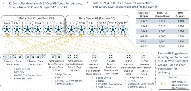
Each SD-WAN router is configured to be a member of two SD-WAN Controller Groups (Groups 1 and 7, Groups 2 and 8, or Groups 3 and 9, Groups 4 and 10, Groups 5 and 11, or Groups 6 and 12) – with one Controller Group in each data center.
Small Branch Sites
Small Branch Sites within each overlay are equally divided into Western Small Branch Sites and Eastern Small Branch Sites.
Western Small Branch Sites
Routers within the Western Small Branch Sites are configured to be members of SD-WAN Controller Groups 5 and 11.
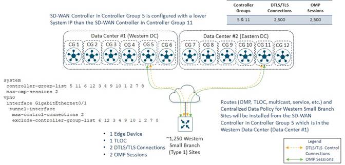
Each Western Small Branch Site has a single SD-WAN router which has a single WAN transport, and therefore a single TLOC.
By default, each SD-WAN router will establish DTLS/TLS control connections to two SD-WAN Controllers over each TLOC. This is controlled at the WAN transport tunnel-interface level by the max-control-connections command. Likewise, each SD-WAN router will establish OMP sessions to two SD-WAN Controllers by default. This is controlled by the max-omp-sessions command. Bank of the Earth decided to leave these settings at the default values.
Each Western Small Branch Site initiates two DTLS/TLS control connections – one to a SD-WAN Controller in Controller Group 5 and the other to a SD-WAN Controller in Controller Group 11. One OMP session is initiated to the SD-WAN Controller in Controller Group 5 over the DTLS/TLS control connection, and one OMP session is initiated to the SD-WAN Controller in Controller Group 11 over the DTLS/TLS control connection – for a total of two OMP sessions per Western Small Branch Site.
Since there are approximately 1,250 Western Small Branch Sites within each overlay, there are a total of 2 x 1,250 = 2,500 DTLS/TLS control connections established between all the Western Small Branch Sites and the SD-WAN Controller instances in Controller Groups 5 and 11. Likewise, there are a total of 2 x 1,250= 2,500 OMP sessions established between all the Western Small Branch Sites and the SD-WAN Controller instances in Controller Groups 5 and 11. More specifically, 1,250 DTLS/TLS control connections and 1,250 OMP Sessions will be formed to the SD-WAN Controller instances in Controller Group 5 and 1,250 DTLS /TLS control connections and 1,250 OMP sessions will be formed to the SD-WAN Controller instances in Controller Group 11.
The SD-WAN Controller instance in Controller Group 5 is configured with a lower System IP address than the SD-WAN Controller instance in Controller Group 11. This ensures that OMP Routes and centralized control policy received from the SD-WAN Controller instance in Controller Group 5 located in Data Center #1 (Western Data Center) are installed into Western Small Site Branch SD-WAN routers during normal operations. This is based on the operation of the OMP best-path algorithm discussed in the following document:
A single SD-WAN Controller in each of Controller Groups 5 and 11 is sufficient to handle 1,250 DTLS/TLS control connections and 1,250 OMP sessions. However, as with Design Option #1, Bank of the Earth specifically implemented the SD-WAN Controller design to address the scenario of a failure of one of the data centers within a given SD-WAN overlay. In the event of a failure of one of the Data Centers, all Western Small Branch Site SD-WAN routers will lose DTLS/TLS control connections and OMP sessions to the SD-WAN Controller instance in the control group to which they belong within that Data Center.
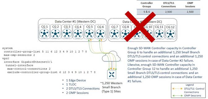
For example, if Data Center #2 fails, the Western Small Branch SD-WAN routers will lose DTLS/TLS control connections and OMP sessions to the SD-WAN Controller instance in Controller Group 11. Because the Western Small Branch SD-WAN routers are configured with the command max-omp-sessions 2 and the WAN transport is configured with the tunnel-interface level command max-control-connections 2, the SD-WAN router will be out of equilibrium – both regarding the number of DTLS/TLS control connections on the WAN transport tunnel-interface and the overall number of OMP sessions it has formed with SD-WAN Controllers.
The SD-WAN routers will attempt to establish a second DTLS/TLS control connection over the WAN Transport tunnel-interface. The WAN transport tunnel-interface has been configured to exclude Controller Groups 6, 12, 3, 4, 9 10, 1, 2, 7, and 8 based on the exclude-controller-group-list configuration. Hence, the SD-WAN routers will establish multiple DTLS/TLS control connections between SD-WAN Controller instances in Controller Groups 5 and 11. There is only one SD-WAN Controller instance in Controller Group 5, so another DTLS/TLS control session and OMP session cannot be formed to a SD-WAN Controller instance within that Controller Group. There are no reachable SD-WAN Controller instances in Controller Group 11. Therefore, the behavior of the SD-WAN routers is that they will fall back and consider all other SD-WAN Controller instances in all other controller groups as if they were part of Controller Group 0 – meaning no Controller Group is assigned to the SD-WAN Controller instance. The SD-WAN routers will then attempt to establish a DTLS/TLS control connections and an OMP sessions to SD-WAN Controller instances based on the order of the SD-WAN Controller Groups within the controller-group-list configuration – 5, 11, 6, 12, 3, 4, 9, 10, 1, 2, 7, and 8. The next Controller Group within the list is Controller Group 6. Therefore, all Western Small Branch SD-WAN routers will establish one additional DTLS/TLS control connection and one additional OMP session to the SD-WAN Controller instance in Controller Group 6.
At this point, each small branch SD-WAN router will have met the requirement for 2 DTLS/TLS control connections for the WAN transport tunnel-interface, as specified in the max-control-connections 2 command, and the requirement for 2 OMP sessions, as specified in max-omp-sessions 2 command.
Likewise, if Data Center #1 fails, the Western Small Branch SD-WAN routers will lose DTLS/TLS control connections and OMP sessions to the SD-WAN Controller instance in Controller Group 5. Western Small Branch SD-WAN routers will establish one additional DTLS/TLS control connection and one additional OMP session to the SD-WAN Controller instance in Controller Group 12 based on the controller-group-list and exclude-controller-group-list configurations.
Eastern Small Branch Sites
Routers within the Eastern Small Branch Sites are configured to be members of SD-WAN Controller Groups 6 and 12.
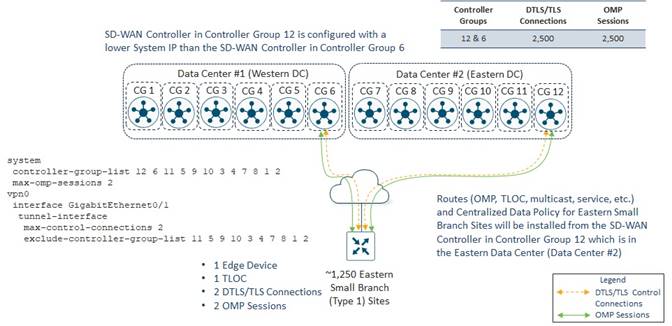
Each Eastern Small Branch Site has a single SD-WAN router which has a single WAN transport, and therefore a single TLOC. Each Eastern Small Branch Site initiates two DTLS/TLS control connections – one to a SD-WAN Controller in Controller Group 12 and the other to a SD-WAN Controller in Controller Group 6. One OMP session is initiated to the SD-WAN Controller in Controller Group 12 over the DTLS/TLS control connection, and one OMP session is initiated to the SD-WAN Controller in Controller Group 6 over the DTLS/TLS control connection – for a total of two OMP sessions per Eastern Small Branch Site.
Since there are approximately 1,250 Eastern Small Branch Sites within each overlay, there are a total of 2 x 1,250 = 2,500 DTLS/TLS control connections established between all the Eastern Small Branch Sites and the SD-WAN Controller instances in Controller Groups 12 and 6. Likewise, there are a total of 2 x 1,250= 2,500 OMP sessions established between all the Eastern Small Branch Sites and the SD-WAN Controller instances in Controller Groups 12 and 6. More specifically, 1,250 DTLS/TLS control connections and 1,250 OMP Sessions will be formed to the SD-WAN Controller instances in Controller Group 12 and 1,250 DTLS /TLS control connections and 1,250 OMP sessions will be formed to the SD-WAN Controller instances in Controller Group 6.
The SD-WAN Controller instance in Controller Group 12 is configured with a lower System IP address than the SD-WAN Controller instance in Controller Group 6. This ensures that OMP routes and centralized control policy received from the SD-WAN Controller instance in Controller Group 12 located in Data Center #2 (Eastern Data Center) are installed into Eastern Small Site branches during normal operations.
A single SD-WAN Controller in each of Controller Groups 12 and 6 is sufficient to handle 1,250 DTLS/TLS control connections and 1,250 OMP sessions. However, as with Design Option #1, Bank of the Earth specifically implemented the SD-WAN Controller design to address the scenario of a failure of one of the data centers within a given SD-WAN overlay. In the event of a failure of one of the data centers, all Eastern Small Branch SD-WAN routers will lose DTLS/TLS control connections and OMP sessions to the SD-WAN Controller instance in the control group to which they belong within that data center.
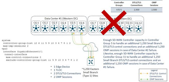
For example, if Data Center #2 fails, the Eastern Small Branch Site SD-WAN routers will lose DTLS/TLS control connections and OMP sessions to the SD-WAN Controller instance in Controller Group 12. Because the Eastern Small Branch Site SD-WAN routers are configured with the command max-omp-sessions 2 and the WAN transport is configured with the tunnel-interface level command max-control-connections 2, the SD-WAN routers will be out of equilibrium – both regarding the number of DTLS/TLS control connections on the WAN transport tunnel-interface and the overall number of OMP sessions they have formed with SD-WAN Controllers.
Each SD-WAN router will attempt to establish a second DTLS/TLS control connection over the WAN Transport tunnel-interface. The WAN transport tunnel-interface has been configured to exclude Controller Groups 11, 5, 9 10, 3, 4, 7, 8, 1, and 2 based on the exclude-controller-group-list configuration. Hence, the SD-WAN router will establish multiple DTLS/TLS control connections between SD-WAN Controller instances in Controller Groups 12 and 6. There are no reachable SD-WAN Controller instances in Controller Group 12. There is only one SD-WAN Controller instance in Controller Group 6, so another DTLS/TLS control session and OMP session cannot be formed to a SD-WAN Controller instance within that Controller Group. Therefore, the behavior of the SD-WAN routers is that they will fall back and consider all other SD-WAN Controller instances in all other controller groups as if they were part of Controller Group 0 – meaning no Controller Group is assigned to the SD-WAN Controller instance. The SD-WAN routers will then attempt to establish a DTLS/TLS control connections and an OMP sessions to SD-WAN Controller instances based on the order of the SD-WAN Controller Groups within the controller-group-list configuration – 12, 6, 11, 5, 9 10, 3, 4, 7, 8, 1, and 2. The next Controller Group within the list is Controller Group 11. However, there are no reachable SD-WAN Controller instances in Controller Group 11. The next Controller Group is 5. Therefore, all Eastern Small Branch Site SD-WAN routers will establish one additional DTLS/TLS control connection and one additional OMP session to the SD-WAN Controller instance in Controller Group 5.
At this point, each Eastern Small Branch Site SD-WAN router will have met the requirement for 2 DTLS/TLS control connections for the WAN transport tunnel-interface, as specified in the max-control-connections 2 command, and the requirement for 2 OMP sessions, as specified in max-omp-sessions 2 command.
Likewise, if Data Center #1 fails, the Eastern Small Branch Site SD-WAN routers will lose DTLS/TLS control connections and OMP sessions to the SD-WAN Controller instance in Controller Group 6. Eastern Small Branch Site SD-WAN routers will establish one additional DTLS/TLS control connection and one additional OMP session to the SD-WAN Controller instance in Controller Group 11 based on the controller-group-list and exclude-controller-group-list configurations.
Small Branch Site Summary
With one SD-WAN Controller in each of Controller Groups 5, 6, 11, and 12 and either Data Center #1 or #2 fails, sufficient SD-WAN Controller capacity is provisioned within Controller Groups 5 and 6 or Controller Groups 11 and 12, to maintain the SD-WAN routers in all the Small Branch Sites – both on the western and eastern sides of the overlay. In other words, all Western Small Branch Site SD-WAN routers are compartmentalized to use only SD-WAN Controller instances within Controller Groups 5 and 11 during normal operations; and to additionally use SD-WAN Controller instances within either Controller Groups 6 or 12 and in the event of the failure of one of the two data centers. Likewise, all Eastern Small Branch Site SD-WAN routers are compartmentalized to use only SD-WAN Controller instances within Controller Groups 6 and 12 during normal operations; and to additionally use SD-WAN Controller instances within either Controller Groups 5 or 11 and in the event of the failure of one of the two data centers.
This provides Bank of the Earth a deterministic way of ensuring there is sufficient SD-WAN Controller capacity for the Small Branch Sites, rather than trying to figure out how to spread individual the DTLS/TLS control connections and OMP sessions across the remaining Controller Groups without overrunning the capacity of any given SD-WAN Controller. This is particularly useful also, as Bank of the Earth adds or removes Small Branch Sites over time. Note that the single SD-WAN Controller instance within each Controller Group already provides some excess capacity for Bank of Earth to add additional Small Branch Sites. However, as before, the downside of this design is that it requires provisioning double the number of SD-WAN Controller instances necessary for all DTLS/TLS control connections and OMP sessions from the Small Branch Sites.
Medium-Sized Branch Sites
As with the Small Branch Sites, Medium-Sized Branch Sites within each overlay are equally divided into Western Medium-Sized Branch Sites and Eastern Medium-Sized Branch Sites.
Western Medium-Sized Branch Sites
Routers within the Western Medium-Sized Branch Sites are configured to be members of SD-WAN Controller Groups 3 and 9.
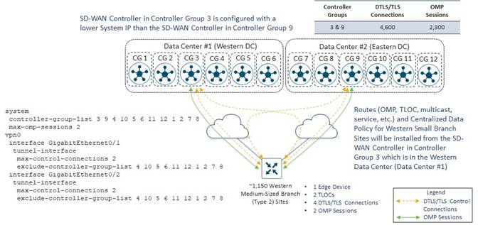
As with the small branch SD-WAN routers, Bank of the Earth decided to leave the max-control-connections and max-omp-sessions settings at their default values of 2.
Each Western Medium-Sized Branch Site has a single SD-WAN router which has a two WAN transports / TLOCs. Therefore, a total of 2 x 2 = 4 DTLS/TLS control connections and two OMP sessions are initiated from each Western Medium-Sized Branch Site. Each Western Medium-Sized Branch Site initiates two DTLS/TLS control connections – one to a SD-WAN Controller instance in Controller Group 3 and the other to a SD-WAN Controller instance in Controller Group 9 – from each of the two WAN transport tunnel-interfaces on the router. One OMP session is established to the SD-WAN Controller instance in Controller Group 3 over one of the DTLS/TLS control connections, and one OMP session is established to the SD-WAN Controller instance in Controller Group 9 over one of the DTLS/TLS control connections.
Since there are approximately 1,150 Western Medium-Sized Branch Sites within each overly overlay, there are a total of 4 x 1,150 = 4,600 DTLS/TLS control connections established between all the Western Medium-Sized Branch Sites and the SD-WAN Controller instances in Controller Groups 3 and 9. Likewise, there are a total of 2 x 1,150= 2,300 OMP sessions established between all the Western Medium-Sized Branch Sites and the SD-WAN Controller instances in Controller Groups 3 and 9. More specifically, 2,300 DTLS/TLS control connections and 1,150 OMP Sessions will be formed to the SD-WAN Controller instance in Controller Group 3 and 2,300 DTLS /TLS control connections and 1,150 OMP sessions will be formed to the SD-WAN Controller instance in Controller Group 9.
The SD-WAN Controller instance in Controller Group 3 is configured with a lower System IP address than the SD-WAN Controller instance in Controller Group 9. This ensures that OMP Routes and centralized control policy received from the SD-WAN Controller instance in Controller Group 3 located in Data Center #1 (Western Data Center) are installed into Western Medium-Sized Site branch SD-WAN routers during normal operations. This is based on the operation of the OMP best-path algorithm discussed in the following document:
A single SD-WAN Controller in each of Controller Groups 3 and 9 is sufficient to handle 4,600 DTLS/TLS control connections and 2,300 OMP sessions. However, as with Design Option #1, Bank of the Earth specifically implemented the SD-WAN Controller design to address the scenario of a failure of one of the data centers within a given SD-WAN overlay. In the event of a failure of one of the data centers, all Western Medium-Sized Branch SD-WAN routers will lose DTLS/TLS control connections and OMP sessions to the SD-WAN Controller instance in the control group to which they belong within that data center.
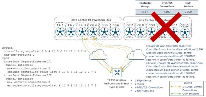
For example, if Data Center #2 fails, the Western Medium-Sized Branch Site SD-WAN routers will lose DTLS/TLS control connections and OMP sessions to the SD-WAN Controller instance in Controller Group 9. Because the Western Medium-Sized Branch Site SD-WAN routers are configured with the command max-omp-sessions 2 and the WAN transport is configured with the tunnel-interface level command max-control-connections 2, the SD-WAN router will be out of equilibrium – both regarding the number of DTLS/TLS control connections per WAN transport tunnel-interface and the overall number of OMP sessions it has formed with SD-WAN Controllers.
The SD-WAN routers will attempt to establish a second DTLS/TLS control connection over each WAN transport tunnel-interface. Each WAN transport tunnel-interface has been configured to exclude Controller Groups 4, 10, 5, 6 11, 12, 1, 2, 7, and 8 based on the exclude-controller-group-list configuration. Hence, the SD-WAN routers will establish multiple DTLS/TLS control connections between SD-WAN Controller instances in Controller Groups 3 and 9. There is only one SD-WAN Controller instance in Controller Group 3, so another DTLS/TLS control session and OMP session cannot be formed to a SD-WAN Controller instance within that Controller Group. There are no reachable SD-WAN Controller instances in Controller Group 9. Therefore, the behavior of the SD-WAN routers is that they will fall back and consider all other SD-WAN Controller instances in all other controller groups as if they were part of Controller Group 0 – meaning no Controller Group is assigned to the SD-WAN Controller instance. The SD-WAN routers will then attempt to establish a DTLS/TLS control connection per WAN transport tunnel-interface and an OMP sessions to SD-WAN Controller instances based on the order of the SD-WAN Controller Groups within the controller-group-list configuration – 3, 9, 4, 10, 5, 6 11, 12, 1, 2, 7, and 8. The next Controller Group within the list is Controller Group 4. Therefore, all Western Medium-Sized Branch SD-WAN routers will establish one additional DTLS/TLS control connection per WAN transport tunnel-interface and one additional OMP session to the SD-WAN Controller instance in Controller Group 4.
At this point, each small branch SD-WAN router will have met the requirement for 2 DTLS/TLS control connections per WAN transport tunnel-interface, as specified in the max-control-connections 2 command, and the requirement for 2 OMP sessions, as specified in max-omp-sessions 2 command.
Likewise, if Data Center #1 fails, the Western Medium-Sized Branch SD-WAN routers will lose DTLS/TLS control connections and OMP sessions to the SD-WAN Controller instance in Controller Group 3. Western Medium-Sized Branch Site SD-WAN routers will establish one additional DTLS/TLS control connection and one additional OMP session to the SD-WAN Controller instance in Controller Group 10 based on the controller-group-list and exclude-controller-group-list configurations.
Eastern Medium-Sized Branch Sites
Routers within the Eastern Medium-Sized Branch Sites are configured to be members of SD-WAN Controller Groups 10 and 4.
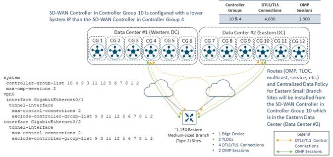
As with the Small Branch Site SD-WAN routers, Bank of the Earth decided to leave the max-control-connections and max-omp-sessions settings at their default values of 2.
Each Eastern Medium-Sized Branch Site has a single SD-WAN router which has a two WAN transports / TLOCs. Therefore, a total of 2 x 2 = 4 DTLS/TLS control connections and two OMP sessions are initiated from each Eastern Medium-Sized Branch Site. Each Eastern Medium-Sized Branch Site initiates two DTLS/TLS control connections – one to a SD-WAN Controller instance in Controller Group 10 and the other to a SD-WAN Controller instance in Controller Group 4 – from each of the two WAN transport tunnel-interfaces on the SD-WAN router. One OMP session is established to the SD-WAN Controller instance in Controller Group 10 over one of the DTLS/TLS control connections, and one OMP session is established to the SD-WAN Controller instance in Controller Group 4 over one of the DTLS/TLS control connections.
Since there are approximately 1,150 Eastern Medium-Sized Branch Sites within each overlay, there are a total of 4 x 1,150 = 4,600 DTLS/TLS control connections established between all the Eastern Medium-Sized Branch Sites and the SD-WAN Controller instances in Controller Groups 10 and 4. Likewise, there are a total of 2 x 1,150= 2,300 OMP sessions established between all the Eastern Medium-Sized Branch Sites and the SD-WAN Controller instances in Controller Groups 10 and 4. More specifically, 2,300 DTLS/TLS control connections and 1,150 OMP Sessions will be formed to the SD-WAN Controller instance in Controller Group 10 and 2,300 DTLS /TLS control connections and 1,150 OMP sessions will be formed to the SD-WAN Controller instance in Controller Group 4.
The SD-WAN Controller instance in Controller Group 10 is configured with a lower System IP address than the SD-WAN Controller instance in Controller Group 4. This ensures that OMP routes and centralized control policy received from the SD-WAN Controller instance in Controller Group 10 located in Data Center #2 (Eastern Data Center) are installed into Eastern Medium-Sized Branch Site SD-WAN routers during normal operations. This is based on the operation of the OMP best-path algorithm discussed in the following document:
A single SD-WAN Controller in each of Controller Groups 10 and 4 is sufficient to handle 4,600 DTLS/TLS control connections and 2,300 OMP sessions. However, as with Design Option #1, Bank of the Earth specifically implemented the SD-WAN Controller design to address the scenario of a failure of one of the data centers within a given SD-WAN overlay. In the event of a failure of one of the data centers, all Eastern Medium-Sized Branch SD-WAN routers will lose DTLS/TLS control connections and OMP sessions to the SD-WAN Controller instance in the control group to which they belong within that data center.
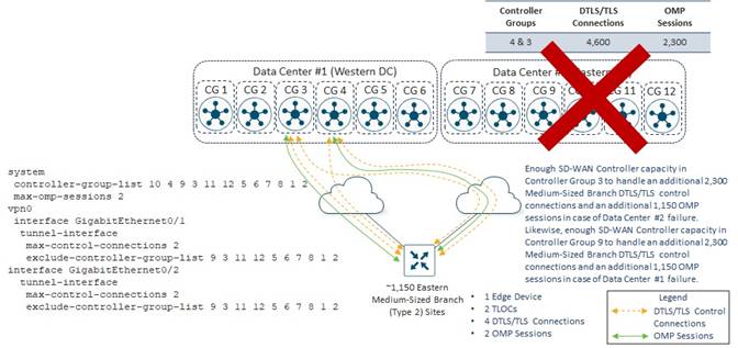
For example, if Data Center #2 fails, the Eastern Medium-Sized Branch Site SD-WAN routers will lose DTLS/TLS control connections and OMP sessions to the SD-WAN Controller instance in Controller Group 10. Because the Eastern Small Branch SD-WAN routers are configured with the command max-omp-sessions 2 and the WAN transports are configured with the tunnel-interface level command max-control-connections 2, the SD-WAN router will be out of equilibrium – both regarding the number of DTLS/TLS control connections per WAN transport tunnel-interface and the overall number of OMP sessions it has formed with SD-WAN Controllers.
The SD-WAN routers will attempt to establish a second DTLS/TLS control connection over each WAN transport tunnel-interface. Each WAN transport tunnel-interface has been configured to exclude Controller Groups 9, 3, 11, 12, 5, 6, 7, 8, 1, and 2 based on the exclude-controller-group-list configuration. Hence, the SD-WAN routers will establish multiple DTLS/TLS control connections between SD-WAN Controller instances in Controller Groups 10 and 4. There are no reachable SD-WAN Controller instances in Controller Group 10. There is only one SD-WAN Controller instance in Controller Group 4, so another DTLS/TLS control session and OMP session cannot be formed to a SD-WAN Controller instance within that Controller Group. Therefore, the behavior of the SD-WAN routers is that they will fall back and consider all other SD-WAN Controller instances in all other controller groups as if they were part of Controller Group 0 – meaning no Controller Group is assigned to the SD-WAN Controller instance.
The SD-WAN routers will then attempt to establish a DTLS/TLS control connection per WAN transport tunnel-interface and an OMP session to SD-WAN Controller instances based on the order of the SD-WAN Controller Groups within the controller-group-list configuration – 10, 4, 9, 3, 11, 12, 5, 6, 7, 8, 1, and 2. The next Controller Group within the list is Controller Group 9. However, there is no reachable SD-WAN Controller instance in Controller Group 9. The next Controller Group within the list is Controller Group 3. Therefore, all Eastern Medium-Sized Branch Site SD-WAN routers will establish one additional DTLS/TLS control connection per WAN transport tunnel-interface and one additional OMP session to the SD-WAN Controller instance in Controller Group 3.
At this point, each Eastern Medium-Sized Branch Site SD-WAN router will have met the requirement for 2 DTLS/TLS control connections per WAN transport tunnel-interface, as specified in the max-control-connections 2 command, and the requirement for 2 OMP sessions, as specified in max-omp-sessions 2 command.
Likewise, if Data Center #1 fails, the Eastern Medium-Sized Branch Site SD-WAN routers will lose DTLS/TLS control connections and OMP sessions to the SD-WAN Controller instance in Controller Group 4. Eastern Medium-Sized Branch Site SD-WAN routers will establish one additional DTLS/TLS control connection and one additional OMP session to the SD-WAN Controller instance in Controller Group 9 based on the controller-group-list and exclude-controller-group-list configurations.
Medium-Sized Branch Site Summary
With one SD-WAN Controller in each of Controller Groups 3, 4, 9, and 10 and either Data Center #1 or #2 fails, sufficient SD-WAN Controller capacity is provisioned within Controller Groups 3 and 4 or Controller Groups 9 and 10, to maintain the SD-WAN routers in all the Medium-Sized Branch Sites – both on the western and eastern sides of the overlay. In other words, all Western Medium-Sized Branch Site SD-WAN routers are compartmentalized to use only SD-WAN Controller instances within Controller Groups 3 and 9 during normal operations; and to additionally use SD-WAN Controller instances within either Controller Groups 4 or 10 and in the event of the failure of one of the two data centers. Likewise, all Eastern Medium-Sized Branch Site SD-WAN routers are compartmentalized to use only SD-WAN Controller instances within Controller Groups 10 and 4 during normal operations; and to additionally use SD-WAN Controller instances within either Controller Groups 9 or 3 and in the event of the failure of one of the two data centers.
This provides Bank of the Earth a deterministic way of ensuring there is sufficient SD-WAN Controller capacity for the Medium-Sized Branch Sites, rather than trying to figure out how to spread individual the DTLS/TLS control connections and OMP sessions across the remaining Controller Groups without overrunning the capacity of any given SD-WAN Controller. This is particularly useful also, as Bank of the Earth adds or removes Medium-Sized Branch Sites over time. Note that the single SD-WAN Controller instance within each Controller Group already provides some excess capacity for Bank of Earth to add additional Medium-Sized Branch Sites. However, as before, the downside of this design is that it requires provisioning double the number of SD-WAN Controller instances necessary for all DTLS/TLS control connections and OMP sessions from the Medium-Sized Branch Sites.
Data Center and Large / Regional Branch Sites
As with the Small and Medium-Sized Branch Sites, both the Data Center and Large / Regional Branch Sites within each overlay are equally divided into Western and Eastern Sites.
Western Data Center and Large / Regional Branch Sites
SD-WAN routers within both the Western Data Center and Large/Regional Branch Sites are configured to be members of SD-WAN Controller Groups 1 and 7.
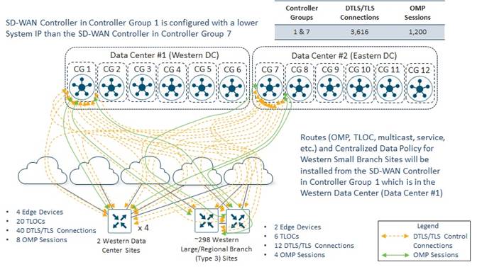
Western Data Center
The Western Data Center has four head-end / hub SD-WAN routers. The reason for four routers is for scalability (both throughput and tunnel capacity) and redundancy. This was discussed earlier within this document.
Each of the Western Data Center SD-WAN routers has five WAN transports / TLOCs (four regional MPLS carriers and one Internet connection). Maintaining consistency throughout their deployment, Bank of the Earth decided to leave the max-control-connections and max-omp-sessions settings at their default values of 2 for the Western Data Center SD-WAN routers, as shown in the configuration example below.
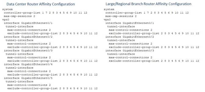
Each Western Data Center SD-WAN router initiates two DTLS/TLS control connections – one to a SD-WAN Controller instance in Controller Group 1 and the other to a SD-WAN Controller instance in Controller Group 7 – from each of the five WAN transport tunnel-interfaces. Since there are four head-end / hub SD-WAN routers within the Western Data Center, there are a total of 2 x 5 x 4 = 40 DTLS/TLS control connections from the Western Data Center. One OMP session is established to the SD-WAN Controller instance in Controller Group 1 over any one of the five DTLS/TLS control connections, and one OMP session is established to the SD-WAN Controller instance in Controller Group 7 over any one of the five DTLS/TLS control connections – for a total of two OMP sessions per Western Data Center SD-WAN router. Again, since there are four Western Data Center SD-WAN routers, there are a total of 2 x 4 = 8 OMP sessions from the Western Data Center. More specifically, 20 DTLS/TLS control connections and 4 OMP Sessions will be formed to the SD-WAN Controller instances in Controller Group 1 and 20 DTLS /TLS control connections and 4 OMP sessions will be formed to the SD-WAN Controller instances in Controller Group 7.
This ensures that OMP routes and centralized control policy received from the SD-WAN Controller instance in Controller Group 1 located in the Western Data Center (Data Center #1) are installed into Western Data Center SD-WAN routers during normal operations. This is based on the operation of the OMP best-path algorithm discussed in the following document:
Western Large / Regional Branch Sites
SD-WAN routers within the Western Large / Regional Branch Sites are also configured to be members of SD-WAN Controller Groups 1 and 7.
Western Large / Regional Branch Sites are configured with two SD-WAN routers. Each Western Large / Regional Branch Site SD-WAN router has a direct WAN transport interface connection to one MPLS regional provider, a direct WAN transport interface connection to an Internet Service Provider (ISP), and a WAN transport interface connection to a second regional MPLS provider via TLOC-Extension through the other SD-WAN router within the Western Large / Regional Branch Site.
Again, for consistency throughout their deployment, Bank of the Earth decided to leave the max-control-connections and max-omp-sessions settings at their default values of 2 for the Western Large / Regional Branch Site SD-WAN routers.
Each Western Large / Regional Branch Site initiates two DTLS/TLS control connections – one to a SD-WAN Controller instance in Controller Group 1 and the other to a SD-WAN Controller instance in Controller Group 7 – from each WAN transport tunnel-interface on each SD-WAN router. Therefore, a total of 2 x 3 x 2 = 12 DTLS/TLS control connections are initiated from each Western Large / Regional Branch Site. One OMP session is established to the SD-WAN Controller instance in Controller Group 1 over one of the DTLS/TLS control connections, and one OMP session is established to the SD-WAN Controller instance in Controller Group 7 over one of the DTLS/TLS control connections – for each SD-WAN router within each Western Large / Regional Branch Site. Because there are two SD-WAN routers within each Western Large / Regional Branch Site, there are a total of 2 x 2 = 4 OMP sessions per Western Large/Regional Branch Site.
Since there are approximately 298 Western Large / Regional Branch Sites within each overlay, there are a total of 12 x 298 = 3,576 DTLS/TLS control connections established between all the Western Large / Regional Branch Site SD-WAN routers and all the SD-WAN Controller instances in Controller Groups 1 and 7. Likewise, there are a total of 4 x 298 = 1,192 OMP sessions established between all the Western Large / Regional Branch Site SD-WAN routers and all the SD-WAN Controller instances in Controller Groups 1 and 7. More specifically, 1,788 DTLS/TLS control connections and 596 OMP Sessions will be formed to the SD-WAN Controller instances in Controller Group 1 and 1,788 DTLS /TLS control connections and 596 OMP sessions will be formed to the SD-WAN Controller instances in Controller Group 7.
Combined Western Data Center and Large / Regional Branch Sites
Summarizing the DTLS/TLS control connections and OMP sessions from both the Western Data Center and Large / Regional Branch Sites, there will be at total of 40 + 3,576 = 3,616 DTLS/TLS control connections established between all the Western Data Center and Large/Regional Branch Site SD-WAN routers and all the SD-WAN Controller instances in Controller Groups 1 and 7. Likewise there are a total of 8 + 1,192 = 1,200 OMP sessions established between all the Western Data Center and Large / Regional Branch Site SD-WAN routers and all the SD-WAN Controller instances in Controller Groups 1 and 7. More specifically 1,808 DTLS/TLS control connections and 600 OMP sessions will be formed to the SD-WAN Controller instances in Controller Group 1 and 1,808 DTLS/TLS control connections and 600 OMP sessions will be formed to the SD-WAN Controller instances in Controller Group 7.
As with the Small and Medium-Sized Branch Site SD-WAN Controller designs, a single SD-WAN Controller in each of Controller Groups 1 and 7 is sufficient to handle 1,808 DTLS/TLS control connections and 600 OMP sessions. However, Bank of the Earth wanted the SD-WAN Controller design to specifically address the scenario of a failure of one of the Data Center Sites within a given SD-WAN overlay. In the event of a failure of one of the Data Center Sites, all Western Data Center and Large / Regional Branch Site SD-WAN routers will lose DTLS/TLS control connections and OMP sessions to the SD-WAN Controller instances in the Controller Group to which they belong within that Data Center.
The SD-WAN Controller instance in Controller Group 1 is configured with a lower System IP address than the SD-WAN Controller instance in Controller Group 7. This ensures that OMP routes and centralized control policy received from the SD-WAN Controller instance in Controller Group 1 located in the Western Data Center (Data Center #1) are installed into Western Data Center and Large / Regional Branch Site SD-WAN routers during normal operations. This is based on the operation of the OMP best-path algorithm discussed in the following document:
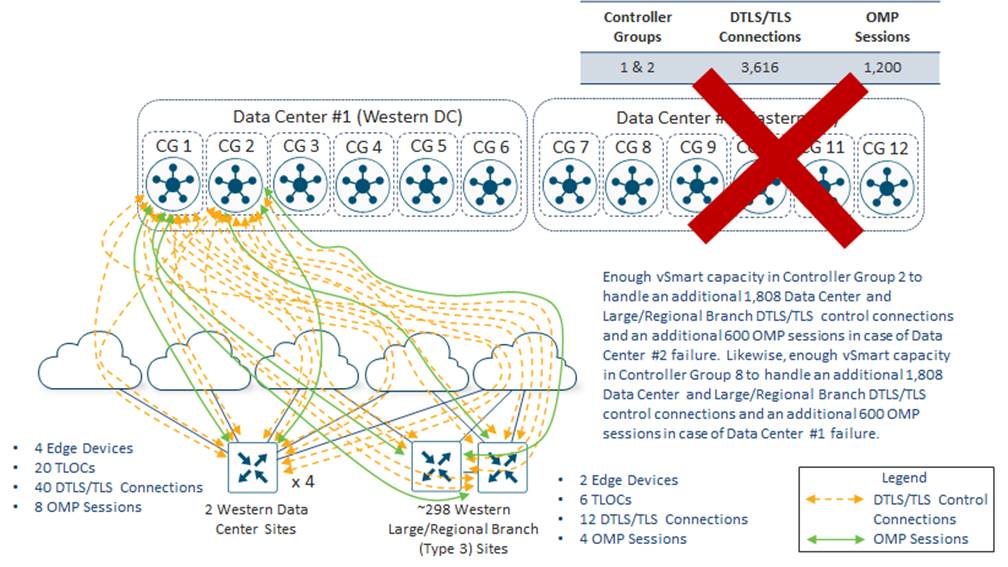
In the example above, if the Eastern Data Center (Data Center #2) fails, the Western Data Center and Large / Regional Branch Site SD-WAN routers will lose DTLS/TLS control connections and OMP sessions to all SD-WAN Controller instances in Controller Group 7. Because the Western Data Center and Large / Regional Branch Site SD-WAN routers are configured with the command max-omp-sessions 2 and each WAN transport is configured with the tunnel-interface level command max-control-connections 2, the SD-WAN routers will be out of equilibrium – both with respect to the number of DTLS/TLS control connections on each WAN transport tunnel-interface and the overall number of OMP sessions established with SD-WAN Controllers.
The SD-WAN routers will attempt to establish a second DTLS/TLS control connection over each WAN transport tunnel-interface. Each WAN transport tunnel-interface has been configured to exclude Controller Groups 2, 8, 3, 4, 5, 6, 9, 10, 11, and 12 based on the exclude-controller-group-list configuration. Hence, the SD-WAN routers will establish multiple DTLS/TLS control connections between SD-WAN Controller instances in Controller Groups 1 and 7. There is only one SD-WAN Controller instance in Controller Group 1, so another DTLS/TLS control session and OMP session cannot be formed to a SD-WAN Controller instance within that Controller Group. There are no reachable SD-WAN Controller instances in Controller Group 7. Therefore, the behavior of the SD-WAN routers is that they will fall back and consider all other SD-WAN Controller instances in all other controller groups as if they were part of Controller Group 0 – meaning no Controller Group is assigned to the SD-WAN Controller instance. The SD-WAN routers will then attempt to establish a DTLS/TLS control connection per WAN transport tunnel-interface and an OMP sessions to SD-WAN Controller instances based on the order of the SD-WAN Controller Groups within the controller-group-list configuration – 1, 7, 2, 8, 3, 4, 5, 6, 9, 10, 11, 12. The next Controller Group within the list is Controller Group 2. Therefore, all Western Data Center and Large / Regional Branch SD-WAN routers will establish one additional DTLS/TLS control connection per WAN transport tunnel-interface and one additional OMP session to the SD-WAN Controller instance in Controller Group 2.
At this point, each Western Data Center and Large / Regional branch SD-WAN router will have met the requirement for 2 DTLS/TLS control connections per WAN transport tunnel-interface, as specified in the max-control-connections 2 command, and the requirement for 2 OMP sessions, as specified in max-omp-sessions 2 command.
Likewise, if the Western Data Center (Data Center #1) fails, the Western Large / Regional Branch Site SD-WAN routers will lose DTLS/TLS control connections and OMP sessions to the SD-WAN Controller instance in Controller Group 3. Western Large / Regional Branch Site SD-WAN routers will establish one additional DTLS/TLS control connection and one additional OMP session to the SD-WAN Controller instance in Controller Group 8 based on the controller-group-list and exclude-controller-group-list configurations.
Eastern Data Center and Large / Regional Branch Sites
SD-WAN routers within the Eastern Data Center and Large/Regional Branch Sites are configured to be members of SD-WAN Controller Groups 8 and 2.
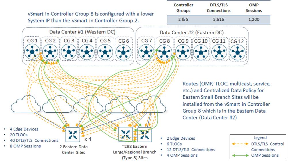
Eastern Data Center
The Eastern Data Center has four head-end / hub SD-WAN routers. The reason for four routers is for scalability (both throughput and tunnel capacity) and redundancy. This was discussed earlier within this document.
Each of the Eastern Data Center SD-WAN routers has five WAN transports / TLOCs (four regional MPLS carriers and one Internet connection). Maintaining consistency throughout their deployment, Bank of the Earth decided to leave the max-control-connections and max-omp-sessions settings at their default values of 2 for the Eastern Data Center SD-WAN routers, as shown in the configuration example below.
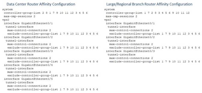
Each Eastern Data Center SD-WAN router initiates two DTLS/TLS control connections – one to a SD-WAN Controller instance in Controller Group 8 and the other to a SD-WAN Controller instance in Controller Group 2 – from each of the five WAN transport tunnel-interfaces. Since there are four head-end / hub SD-WAN routers within the Eastern Data Center, there are a total of 2 x 5 x 4 = 40 DTLS/TLS control connections from the Eastern Data Center. One OMP session is established to the SD-WAN Controller instance in Controller Group 8 over any one of the five DTLS/TLS control connections, and one OMP session is established to the SD-WAN Controller instance in Controller Group 2 over any one of the five DTLS/TLS control connections – for a total of two OMP sessions per Eastern Data Center SD-WAN router. Again, since there are four Eastern Data Center SD-WAN routers, there are a total of 2 x 4 = 8 OMP sessions from the Eastern Data Center. More specifically, 20 DTLS/TLS control connections and 4 OMP Sessions will be formed to the SD-WAN Controller instances in Controller Group 8 and 20 DTLS /TLS control connections and 4 OMP sessions will be formed to the SD-WAN Controller instances in Controller Group 2.
Eastern Western Large / Regional Branch Sites
SD-WAN routers within the Eastern Large / Regional Branch Sites are also configured to be members of SD-WAN Controller Groups 1 and 7.
Eastern Large / Regional Branch Sites are configured with two SD-WAN routers. Each Eastern Large / Regional Branch Site SD-WAN router has a direct WAN transport interface connection to one MPLS regional provider, a direct WAN transport interface connection to an Internet Service Provider (ISP), and a WAN transport interface connection to a second regional MPLS provider via TLOC-Extension through the other SD-WAN router within the Eastern Large / Regional Branch Site.
Again, for consistency throughout their deployment, Bank of the Earth decided to leave the max-control-connections and max-omp-sessions settings at their default values of 2 for the Eastern Large / Regional Branch Site SD-WAN routers.
Each Eastern Large / Regional Branch Site initiates two DTLS/TLS control connections – one to a SD-WAN Controller instance in Controller Group 8 and the other to a SD-WAN Controller instance in Controller Group 2 – from each WAN transport tunnel-interface on each SD-WAN router. Therefore, a total of 2 x 3 x 2 = 12 DTLS/TLS control connections are initiated from each Eastern Large / Regional Branch Site. One OMP session is established to the SD-WAN Controller instance in Controller Group 8 over one of the DTLS/TLS control connections, and one OMP session is established to the SD-WAN Controller instance in Controller Group 2 over one of the DTLS/TLS control connections – for each SD-WAN router within each Eastern Large / Regional Branch Site. Because there are two SD-WAN routers within each Eastern Large / Regional Branch Site, there are a total of 2 x 2 = 4 OMP sessions per Eastern Large/Regional Branch Site.
Since there are approximately 298 Eastern Large / Regional Branch Sites within each overlay, there are a total of 12 x 298 = 3,576 DTLS/TLS control connections established between all the Eastern Large / Regional Branch Site SD-WAN routers and all the SD-WAN Controller instances in Controller Groups 8 and 2. Likewise, there are a total of 4 x 298 = 1,192 OMP sessions established between all the Eastern Large / Regional Branch Site SD-WAN routers and all the SD-WAN Controller instances in Controller Groups 8 and 2. More specifically, 1,788 DTLS/TLS control connections and 596 OMP Sessions will be formed to the SD-WAN Controller instances in Controller Group 8 and 1,788 DTLS /TLS control connections and 596 OMP sessions will be formed to the SD-WAN Controller instances in Controller Group 2.
Combined Eastern Data Center and Large / Regional Branch Sites
Summarizing the DTLS/TLS control connections and OMP sessions from both the Eastern Data Center and Large / Regional Branch Sites, there will be at total of 40 + 3,576 = 3,616 DTLS/TLS control connections established between all the Eastern Data Center and Large/Regional Branch Site SD-WAN routers and all the SD-WAN Controller instances in Controller Groups 8 and 2. Likewise there are a total of 8 + 1,192 = 1,200 OMP sessions established between all the Eastern Data Center and Large / Regional Branch Site SD-WAN routers and all the SD-WAN Controller instances in Controller Groups 8 and 2. More specifically 1,808 DTLS/TLS control connections and 600 OMP sessions will be formed to the SD-WAN Controller instances in Controller Group 8 and 1,808 DTLS/TLS control connections and 600 OMP sessions will be formed to the SD-WAN Controller instances in Controller Group 2.
As with the Small and Medium-Sized Branch Site SD-WAN Controller designs, a single SD-WAN Controller in each of Controller Groups 8 and 2 is sufficient to handle 1,808 DTLS/TLS control connections and 600 OMP sessions. However, Bank of the Earth wanted the SD-WAN Controller design to specifically address the scenario of a failure of one of the Data Center Sites within a given SD-WAN overlay. In the event of a failure of one of the Data Center Sites, all Eastern Data Center and Large / Regional Branch Site SD-WAN routers will lose DTLS/TLS control connections and OMP sessions to the SD-WAN Controller instances in the Controller Group to which they belong within that Data Center.
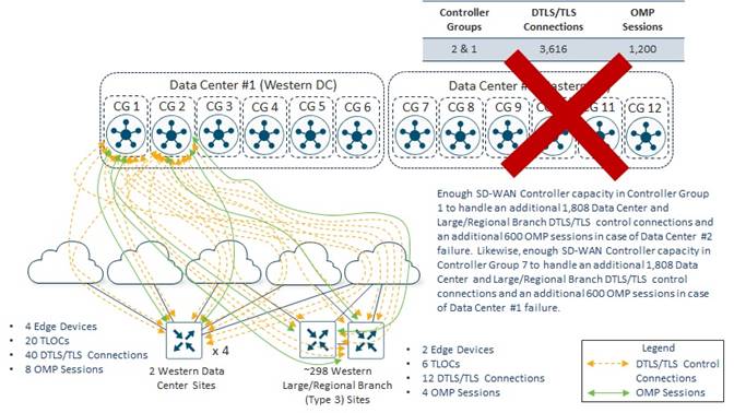
In the example above, if the Eastern Data Center (Data Center #2) fails, the Western Data Center and Large / Regional Branch Site SD-WAN routers will lose DTLS/TLS control connections and OMP sessions to all SD-WAN Controller instances in Controller Group 8. Because the Eastern Data Center and Large / Regional Branch Site SD-WAN routers are configured with the command max-omp-sessions 2 and each WAN transport is configured with the tunnel-interface level command max-control-connections 2, the SD-WAN routers will be out of equilibrium – both with respect to the number of DTLS/TLS control connections on each WAN transport tunnel-interface and the overall number of OMP sessions established with SD-WAN Controllers.
The SD-WAN routers will attempt to establish a second DTLS/TLS control connection over each WAN transport tunnel-interface. Each WAN transport tunnel-interface has been configured to exclude Controller Groups 1, 7, 9, 10, 11, 12, 3, 4, 5, and 6 based on the exclude-controller-group-list configuration. Hence, the SD-WAN routers will establish multiple DTLS/TLS control connections between SD-WAN Controller instances in Controller Groups 8 and 2. There are no reachable SD-WAN Controller instances in Controller Group 7. There is only one SD-WAN Controller instance in Controller Group 2, so another DTLS/TLS control session and OMP session cannot be formed to a SD-WAN Controller instance within that Controller Group. Therefore, the behavior of the SD-WAN routers is that they will fall back and consider all other SD-WAN Controller instances in all other controller groups as if they were part of Controller Group 0 – meaning no Controller Group is assigned to the SD-WAN Controller instance. The SD-WAN routers will then attempt to establish a DTLS/TLS control connection per WAN transport tunnel-interface and an OMP sessions to SD-WAN Controller instances based on the order of the SD-WAN Controller Groups within the controller-group-list configuration – 8, 2, 1, 7, 9, 10, 11, 12, 3, 4, 5, and 6. The next Controller Group within the list is Controller Group 1. Therefore, all Eastern Large / Regional Branch SD-WAN routers will establish one additional DTLS/TLS control connection per WAN transport tunnel-interface and one additional OMP session to the SD-WAN Controller instance in Controller Group 1.
At this point, each Eastern Large / Regional branch SD-WAN router will have met the requirement for 2 DTLS/TLS control connections per WAN transport tunnel-interface, as specified in the max-control-connections 2 command, and the requirement for 2 OMP sessions, as specified in max-omp-sessions 2 command.
Likewise, if the Western Data Center (Data Center #1) fails, the Eastern Data Center and Large / Regional Branch Site SD-WAN routers will lose DTLS/TLS control connections and OMP sessions to the SD-WAN Controller instance in Controller Group 2. Eastern Data Center and Large / Regional Branch Site SD-WAN routers will establish one additional DTLS/TLS control connection and one additional OMP session to the SD-WAN Controller instance in Controller Group 7 based on the controller-group-list and exclude-controller-group-list configurations.
Data Center and Large / Regional Branch Site Summary
With one SD-WAN Controller in each of Controller Groups 1, 2, 7, and 8 and either Data Center #1 or #2 fails, sufficient SD-WAN Controller capacity is provisioned within Controller Groups 1 and 2 or Controller Groups 7 and 8, to maintain the SD-WAN routers in all the Data Center and Large / Regional Branch Sites – both on the western and eastern sides of the overlay. In other words, all Western Data Center and Large / Regional Branch Site SD-WAN routers are compartmentalized to use only SD-WAN Controller instances within Controller Groups 1 and 7 during normal operations; and to additionally use SD-WAN Controller instances within either Controller Groups 2 or 8 and in the event of the failure of one of the two Data Centers. Likewise, all Eastern Data Center and Large / Regional Branch Site SD-WAN routers are compartmentalized to use only SD-WAN Controller instances within Controller Groups 8 and 2 during normal operations; and to additionally use SD-WAN Controller instances within either Controller Groups 7 or 1 and in the event of the failure of one of the two Data Centers.
This provides Bank of the Earth a deterministic way of ensuring there is sufficient SD-WAN Controller capacity for the Data Center and Large / Regional Branch Sites, rather than trying to figure out how to spread individual the DTLS/TLS control connections and OMP sessions across the remaining Controller Groups without overrunning the capacity of any given SD-WAN Controller. This is particularly useful also, as Bank of the Earth adds or removes Large / Regional Branch Sites over time. Note that the single SD-WAN Controller instance within each Controller Group already provides some excess capacity for Bank of Earth to add additional Large / Regional Branch Sites. However, as before, the downside of this design is that it requires provisioning double the number of SD-WAN Controller instances necessary for all DTLS/TLS control connections and OMP sessions from the Data Center and Large / Regional Branch Sites.
Appendix D: SD-WAN Controller Affinity Deep-Dive
This Appendix presents a deep-dive into how SD-WAN routers (also referred to as WAN Edge devices) learn about the SD-WAN Controller instances available within an SD-WAN overlay and determine to which instances to form DTLS/TLS control connections and OMP sessions.
As shown in the following figure, SD-WAN Manager and SD-WAN Controllers initially contact and authenticate to SD-WAN Validator instances, forming persistent DTLS connections, and then subsequently establish and maintain persistent DTLS/TLS connections with each other.
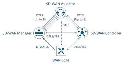
Each core (up to a maximum of 8) on each SD-WAN Manager and SD-WAN Controller instance initiates and maintains a DTLS control connection to each SD-WAN Validator instance in the overlay. For example, if a SD-WAN Controller instance has 2 vCPUs (which translates to 2 cores), a total of 2 DTLS control connections will be established and maintained from the SD-WAN Controller instance to each SD-WAN Validator instance.
When an SD-WAN router (WAN Edge device) initially comes up, it will attempt to establish a temporary / transient DTLS control connection to a SD-WAN Validator instance within the overlay, over each WAN transport / TLOC.
| Technical Note: |
| If multiple SD-WAN Validator instances are provisioned within the overlay, a best practice is to distribute the DTLS control connections from the WAN Edge devices across the available SD-WAN Validator instances using a mechanism such as DNS round robin. With this approach, a DNS A record is used to translate the Fully Qualified Domain Name (FQDN) of the SD-WAN Validator controller to the multiple IP addresses, each corresponding to a specific SD-WAN Validator instance within the overlay. The DNS server then responds to individual requests by sending the various IP addresses of the SD-WAN Validator instances in a round robin fashion. If an SD-WAN deployment crosses multiple geographic areas – such as EMEA, APAC, and the Americas; as an extension of this design, sets of SD-WAN Validator instances can be provisioned within each geographic area, and the DNS resolution can be specific to the SD-WAN Validator instances within that area. |
Once the individual TLOC of the SD-WAN router establishes the DTLS control connection with a SD-WAN Validator instance, the TLOC will register itself with the SD-WAN Validator. In this respect, individual TLOCs of SD-WAN routers act independently of each other.
| Technical Note: |
| The registration process is also how the SD-WAN Validator (acting as a STUN server) learns about any NAT translations between the specific WAN interface / TLOC of the SD-WAN router and the SD-WAN Validator itself. The information regarding the public (NATed IP address, when a NAT device exists) and private (IP address configured on the interface itself) IP addresses is used during tunnel establishment between the SD-WAN routers and the SD-WAN Manager and SD-WAN Controllers as well as between SD-WAN routers. |
Since each core of each SD-WAN Controller instance within the overlay establishes a DTLS control connection to each SD-WAN Validator instance, each SD-WAN Validator knows about all the SD-WAN Controller instances and cores within the overlay.
| Technical Note: |
| There are no DTLS control connections between SD-WAN Validator instances. Each SD-WAN Validator instance acts independently within the overlay. |
Within the registration response, the SD-WAN Validator will send the list of SD-WAN Controller instances in the overlay to the individual TLOC of the SD-WAN router. Since each TLOC of a given SD-WAN router established a DTLS control connection to a SD-WAN Validator instance, each individual TLOC receives the list of SD-WAN Controller instances within the overlay.
Behavior when SD-WAN Controller Affinity is Not Configured within the Overlay
This section discusses how individual TLOCs of SD-WAN routers choose which SD-WAN Controller instances to establish DTLS/TLS control connections, when SD-WAN Controller Affinity is not configured within the overlay – meaning that none of the SD-WAN Controller instances are configured with SD-WAN Controller Groups and none of the SD-WAN routers within the deployment are configured with system-level controller-group-list and tunnel-interface level exclude-controller-group-list commands.
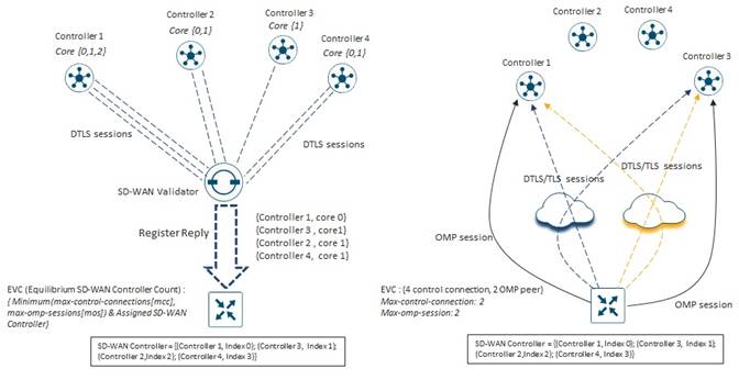
As previously mentioned, each core of each SD-WAN Controller instance establishes a persistent DTLS connection with each SD-WAN Validator instance within the overlay. When an SD-WAN router TLOC establishes a temporary / transient DTLS connection to a SD-WAN Validator instance, the SD-WAN Validator will send the list of available SD-WAN Controller instances to the SD-WAN router TLOC as part of the registration response. For SD-WAN Controller instances with multiple cores, the SD-WAN Validator will select one of the SD-WAN Controller cores, such that for each SD-WAN Controller instance in the overlay, only one entry is sent to the SD-WAN router TLOC. The SD-WAN Validator will determine which core to send within a given registration response to balance DTLS control connections across all the cores within a given SD-WAN Controller instance.
Each SD-WAN Controller instance within the list, is mapped to an index number on the SD-WAN router, based upon the number of SD-WAN Controller instances sent in the registration response from the SD-WAN Validator. For example, in the figure above there are 4 SD-WAN Controller instances (SD-WAN Controller 1 through SD-WAN Controller 4), each of which is assigned to an index (0 through 3). Because no Controller Groups have been configured on any of the SD-WAN Controllers, no controller group information is included within the list of SD-WAN Controllers sent from the SD-WAN Validator to the SD-WAN router TLOC. In this configuration, all SD-WAN Controllers are essentially considered to be in Controller Group 0 – the default controller group. Hence, all SD-WAN Controllers are treated equally in terms of the SD-WAN router TLOC establishing DTLS control connections.
Each SD-WAN router TLOC will “randomly” select an index number within the list to begin establishing DTLS control connections to individual SD-WAN Controller instances. From this starting point within the list of SD-WAN Controllers, the TLOC on the SD-WAN router will sequentially establish DTLS control sessions to SD-WAN Controller instances in the list, up to the tunnel-interface level max-control-connections setting of the TLOC – looping back to the start of the list if necessary. The starting point within the list is determined by each individual SD-WAN router TLOC based on a hash which includes the System IP address of the SD-WAN router. This is designed to introduce randomness across different SD-WAN routers so that overall, the DTLS control connections are balanced across the various SD-WAN Controller instances within the deployment. It also ensures that multiple TLOCs on the same SD-WAN router always start at the same point in the SD-WAN Controller list sent from the SD-WAN Validator instances, since all TLOCs on the same SD-WAN router share the same System IP address.
In the figure above the tunnel-interface level max-control-connections and the max-OMP-session settings have been left at their default value of 2. The list of SD-WAN Controller instances with their index numbers is as follows:
● SD-WAN Controller 1 – Index 0
● SD-WAN Controller 3 – Index 1
● SD-WAN Controller 2 – Index 2
● SD-WAN Controller 4 – Index 3
In the example in the figure above, each TLOC of the SD-WAN router has “randomly” determined that the starting point in the SD-WAN Controller list is Index 0 corresponding to SD-WAN Controller 1. Hence, each TLOC of the SD-WAN router will establish one DTLS control connection to SD-WAN Controller 1. Since the tunnel-interface level max-control-connections (MCC) setting is left at its default value of 2, each TLOC will select the SD-WAN Controller with the next sequential index number (Index 1, corresponding to SD-WAN Controller 3 in the example above) to establish a second DTLS control connection.
Once the DTLS control connections are established, the tunnel-interface level max-control-connections (MCC) setting has been met for each of the TLOCs on the SD-WAN router. Note also, that the SD-WAN Controller 1 and SD-WAN Controller 3 instances are now considered to be the “assigned” SD-WAN Controller instances to which each TLOC for that particular SD-WAN router should have control sessions established.
Continuing with our example with the figure below, we can see that with multiple SD-WAN routers, each router will “randomly” determine the starting index within the list of SD-WAN Controller instances sent from the SD-WAN Validator, from which to begin establishing DTLS control connections.
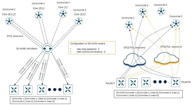
We can see on the right side of the figure above that the first router (Router1) establishes DTLS control connections starting with the SD-WAN Controller with Index 0 (SD-WAN Controller 1) and continuing sequentially with the SD-WAN Controller with Index 1 (SD-WAN Controller 3). The last router (RouterN) establishes DTLS control connections starting with the SD-WAN Controller with Index 1 (SD-WAN Controller 3) and continuing sequentially with the SD-WAN Controller with Index 2 (SD-WAN Controller 2).
In the example above, the max-omp-sessions (MOS) setting is for the SD-WAN router is also left at the default value of 2. Hence, Router1 will establish an OMP session to each of the two SD-WAN Controller instances (SD-WAN Controller 1 and SD-WAN Controller 3 in the example above). When there are multiple TLOCs on the SD-WAN router, each of which have DTLS control connections established to a SD-WAN Controller instance, the OMP session can run over any of these DTLS control connections. There is no configuration to control or command to view over which DTLS control connection the OMP session is established. The benefit of having multiple DTLS control connections to the same SD-WAN Controller instance, established over different TLOCs, is that if a given WAN transport interface on the SD-WAN router goes down, if the OMP session was running over that DTLS session, the SD-WAN router can simply switch to the other DTLS session over the other WAN transport interface / TLOC for the OMP session. Hence there is no loss of OMP peering between the SD-WAN router and the SD-WAN Controller in the event of the loss of a given WAN transport interface / TLOC on the router.
Once the DTLS control connections and OMP sessions are formed to the “assigned” SD-WAN Controller instances, each TLOC of the SD-WAN router is considered to be in Equilibrium SD-WAN Controller Count (EVC) with respect to the DTLS control connections to which the TLOC is configured; and the SD-WAN router is considered to be in Equilibrium SD-WAN Controller Count (EVC) with respect to the number of OMP sessions established to SD-WAN Controller instances.
Behavior when SD-WAN Controller Affinity is Configured within the Overlay
When designing a large SD-WAN deployment it is generally recommended to separate SD-WAN Controller instances into different Controller Groups, and then use the system-level controller-group-list and tunnel-interface level exclude-controller-group-list commands on the SD-WAN routers such that certain SD-WAN routers form DTLS/TLS control connections and OMP sessions to certain SD-WAN Controller instances.
This section discusses how individual TLOCs of SD-WAN routers choose which SD-WAN Controller instances to establish DTLS/TLS control connections with, when SD-WAN Controller Affinity is configured within the overlay.
When SD-WAN Controller instances are configured to be part of a Controller Group, the Controller Group ID information is sent to the SD-WAN Validator instances – when the SD-WAN Controller instances establish persistent connections to the SD-WAN Validator instances. The SD-WAN Validator instances will in turn include Controller Group ID information within the list of available SD-WAN Controllers sent to individual SD-WAN router TLOCs – when they form temporary / transient DTLS connections to the SD-WAN Validator instances.
| Technical Note: |
| When using SD-WAN Controller Affinity, any SD-WAN Controller instance not configured with a Controller Group ID is automatically considered to be part of Controller Group 0 – the default Controller Group. |
The use of SD-WAN Controller Affinity introduces two additional SD-WAN router configuration commands – the system-level controller-group-list command and the tunnel-interface level exclude-controller-group-list command. The system-level controller-group-list command is used to indicate to which SD-WAN Controller Groups the SD-WAN router belongs – in order of preference. Individual TLOCs on the SD-WAN router use this list to determine which SD-WAN Controller instances are eligible for the TLOC to establish a DTLS/TLS control connection with. The tunnel-interface level exclude-controller-group-list command is used to indicate to which SD-WAN Controller Groups a specific TLOC on the SD-WAN router should not establish DTLS/TLS control connections. The exclude-controller-group-list must be a subset of the controller-group-list.
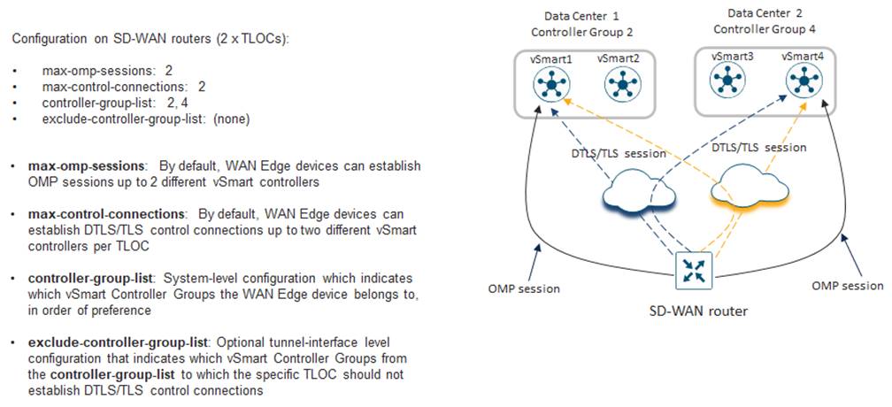
In the example above, a total of four SD-WAN Controller instances have been provisioned within the SD-WAN overlay. Two SD-WAN Controller instances (SD-WAN Controller 1 and SD-WAN Controller 2) are configured with Controller Group 2 in Data Center 1. Two additional SD-WAN Controller instances (SD-WAN Controller 3 and SD-WAN Controller 4) are configured with Controller Group 4 in Data Center 2. A single branch router is provisioned with two WAN interfaces / TLOCs. The max-omp-sessions and the tunnel-interface level max-control-connections settings have been left at their default values of 2. The system-level controller-group-list command includes both SD-WAN Controller Groups (2 and 4). The tunnel-interface level exclude-controller-group-list command is optional and not configured on either TLOC of the SD-WAN router. This means that each TLOC is allowed to establish DTLS/TLS control connections to SD-WAN Controller instances within any of the Controller Groups listed in the controller-group-list.
In this configuration, the behavior of the SD-WAN router is that each TLOC will establish one DTLS/TLS control connection to a SD-WAN Controller instance in Controller Group 2 (SD-WAN Controller 1 or SD-WAN Controller 2), and a second DTLS/TLS control connection to a SD-WAN Controller instance in Controller Group 4 (SD-WAN Controller 3 or SD-WAN Controller 4) – in that order.
In the figure above, the branch router is shown to have established the first DTLS/TLS control connection to the first SD-WAN Controller (SD-WAN Controller 1) in Controller Group 2, and the second DTLS/TLS control connection to the first SD-WAN Controller (SD-WAN Controller 3) in Controller Group 4. However, as was discussed in the section above (no SD-WAN Controller Affinity), each SD-WAN router TLOC “randomly” selects one of the SD-WAN Controller instances within each Controller Group to begin establishing DTLS/TLS control connections – based on a hashing algorithm which includes the System IP address of the SD-WAN router. In other words, within each Controller Group, if there are multiple SD-WAN Controller instances, each SD-WAN router will individually determine the starting point within the specific Controller Group to which to begin establishing DTLS/TLS control connections to SD-WAN Controller instances within that specific Controller Group.
Also, as was discussed in the section above (no SD-WAN Controller Affinity), if DTLS/TLS control connections need to be formed to multiple SD-WAN Controller instances within the same Controller Group, the SD-WAN router TLOC will sequentially select the SD-WAN Controller instances within the Controller Group – looping back to the start of the list of SD-WAN Controller instances within that Controller Group if the end has been reached. For example, if the SD-WAN router TLOC initially establishes a DTLS/TLS control connection to SD-WAN Controller 2 within Controller Group 2, and if there are no SD-WAN Controller instances within Controller Group 4, the SD-WAN router TLOC will establish a second DTLS/TLS control connection to SD-WAN Controller 1 within Controller Group 2.
Continuing with our example with the figure below, we can see that with multiple SD-WAN routers, each router will “randomly” determine the starting index within the list of SD-WAN Controller instances sent from the SD-WAN Validator for each Controller Group, from which to begin establishing DTLS control connections – up to the max-control-connections setting for the TLOC.
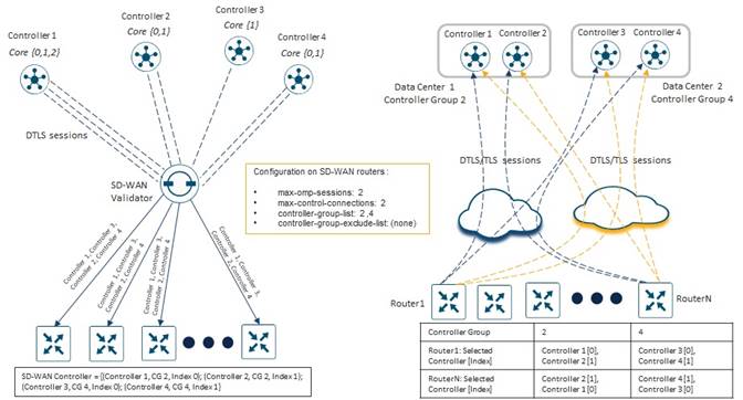
In the figure above, all the SD-WAN routers in the example have been configured with the controller-group-list setting of 2,4 and with no exclude-controller-group-list on any of their TLOCs. We can see on the right side of the figure above that the first router (Router1) establishes DTLS control connections starting with the SD-WAN Controller with Index 0 (SD-WAN Controller 1) of Controller Group 2 and continuing sequentially with the SD-WAN Controller with Index 0 (SD-WAN Controller 3) of Controller Group 4. The last router (RouterN) establishes DTLS control connections starting with the SD-WAN Controller with Index 1 (SD-WAN Controller 2) of Controller Group 2 and continuing sequentially with the SD-WAN Controller with Index 1 (SD-WAN Controller 2) of Controller Group 4.
In the example above, the max-omp-sessions (MOS) setting is for the SD-WAN router is also left at the default value of 2. Hence, Router1 will establish an OMP session to each of the two SD-WAN Controller instances (SD-WAN Controller 1 and SD-WAN Controller 3 in the example above).
Once the DTLS control connections and OMP sessions are formed to the “assigned” SD-WAN Controller instances – this time taking into account the controller-group-list configuration on each SD-WAN router – each TLOC of the SD-WAN router is considered to be in Equilibrium SD-WAN Controller Count (EVC) with respect to the DTLS control connections to which the TLOC is configured; and the SD-WAN router is considered to be in Equilibrium SD-WAN Controller Count (EVC) with respect to the number of OMP sessions established to SD-WAN Controller instances.
In the next example, an exclude-controller-group-list has been configured on both TLOCs of the SD-WAN router.
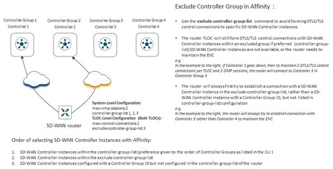
In the example above, each of the TLOCs on the SD-WAN router has been configured to exclude SD-WAN Controller instances in Controller Group 3. When all SD-WAN Controller instances are available, each of the TLOCs of the SD-WAN router will form a DTLS/TLS control connection to SD-WAN Controller 1 and then to SD-WAN Controller 2 – in that order – based on the system-level controller-group-list configuration. However, if SD-WAN Controller 2 is unavailable, each of the TLOCs will form a DTLS/TLS control connection to SD-WAN Controller 1 and then to SD-WAN Controller 3 – even though SD-WAN Controller 3 is part of Controller Group 3, which is in the exclude-controller-group-list for each of the TLOCs.
This example points out that the SD-WAN Controller instances within the Controller Groups listed in the system-level controller-group-list configuration are only considered to be the “preferred” Controller Groups to which an individual TLOC should attempt to establish a DTLS/TLS control connection, during normal operations. If there are no available SD-WAN Controller instances within any of the “preferred” Controller Groups (meaning those Controller Groups listed within the system-level controller-group-list configuration), each TLOC will attempt to establish DTLS/TLS control connections to SD-WAN Controller instances within the tunnel-interface level exclude-controller-group-list. This is done to reach Equilibrium SD-WAN Controller Count (EVC) – meaning the maximum-control-connections (MCC) configuration for the given TLOC as well as the maximum-omp-sessions (MOS) configuration for the SD-WAN router.
A best practice when using SD-WAN Controller Affinity is to assign all SD-WAN Controller instances within an overlay to a Controller Group and list all Controller Groups in the controller-group-list of each SD-WAN router (WAN Edge device) within the overlay – if the desired behavior is to allow all SD-WAN routers to connect to any SD-WAN Controller instance as a last resort.
Appendix E: Examples for Calculating OMP Routes (RIB-in & RIB-out) in a Deployment
This Appendix is designed to provide the reader a general overview of how to calculate the number of received routes (RIB-in) and sent routes (RIB-out) for SD-WAN Controller instances within an SD-WAN deployment.
Received Routes (RIB-in) Calculation
The following figure shows an example network which will be used to explain how the calculations for routes received for each SD-WAN Controller instance is performed.
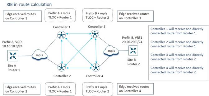
In the figure above, we define the terms “edge received routes” or “directly connected routes” to mean routes received by a given SD-WAN Controller instance from SD-WAN routers which have OMP peering relationships with that SD-WAN Controller instance. Site A has a single SD-WAN router (Router 1) with a single WAN interface configured for TLOC color mpls. Site A also has a single Service VPN (VRF) which has a single IPv4 unicast prefix (Prefix A). Site B also has a single SD-WAN router (Router 2) with a single WAN interface configured for TLOC color mpls. Site B also has a single Service VPN (VRF) which has a single IPv4 unicast prefix (Prefix B).
The SD-WAN router in Site A has OMP peering relationships with SD-WAN Controller 1 and SD-WAN Controller 2. Based on the OMP peering relationships, SD-WAN Controller 1 and SD-WAN Controller 2 both receive a directly connected route from Router 1 to Prefix A via the mpls TLOC of Router 1. Likewise, SD-WAN Controller 3 and SD-WAN Controller 4 both receive a directly connected route to Prefix B from Router 2, via the mpls TLOC of Router 2. These are shown in the figure above.
| Technical Note: |
| Technically, a TLOC consists of the following tuple of information: the System IP address of the SD-WAN router, the Color assigned to the SD-WAN tunnel interface (also known as the TLOC Color), and the encapsulation type (IPsec or GRE). In the discussion above, this is referred to as the “mpls TLOC” for simplicity. |
Since all SD-WAN Controller instances within an overlay are fully-meshed – meaning they have OMP peering relationships with each other – each SD-WAN Controller will reflect the directly connected routes it receives from SD-WAN routers peered with it, to the other SD-WAN Controller instances within the overlay.
| Technical Note: |
| A SD-WAN Controller instance will not reflect a route received from one SD-WAN Controller instance to another SD-WAN Controller instance. Only routes that are directly received from SD-WAN routers (also known as Edge devices) are reflected to other SD-WAN Controller instances. |
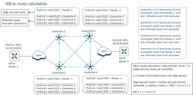
If we take a closer look at SD-WAN Controller 1 in the figure above, we can see that in addition to the directly connected route to Prefix A via the mpls TLOC of Router 1, from the router; SD-WAN Controller 1 will also receive a route to Prefix A via the mpls TLOC of Router 1, from SD-WAN Controller 2. Additionally, SD-WAN Controller 1 will receive a route to Prefix B via the mpls TLOC of Router 2, from SD-WAN Controller 3; and a route to Prefix B via the mpls TLOC of Router 2, from SD-WAN Controller 4.
Hence, in our example network, SD-WAN Controller 1 has a total of four received routes as shown in the figure above. One route (Prefix A via the mpls TLOC of Router 1) is from an SD-WAN router directly peered with SD-WAN Controller 1. This is a “directly connected route” or “edge receive route”. The same route (Prefix A via the mpls TLOC of Router 1) is also received as a “reflected route” from SD-WAN Controller 2. There are also two reflected routes to Prefix B via the mpls TLOC of Router 2 – one from SD-WAN Controller 3 and one from SD-WAN Controller 4.
The same logic can be applied to each of the SD-WAN Controllers in the example network in the figure above. As can be seen, each of the SD-WAN Controllers has a total of four received routes. Hence, the size of the RIB-in table of each of the SD-WAN Controller instances in the example network shown in the figure above is four routes.
The calculation of received routes (hence the size of the RIB-in table) per SD-WAN Controller in this example network can then be summarized as follows:
Received routes (RIB-in) calculation =
Edge received routes + (n x Edge received routes per SD-WAN Controller)
where:
n = Number of SD-WAN Controller peers with edge devices
and:
Edge received routes =
Number of routers with OMP sessions (directly connected) to the
SD-WAN Controller x
Number of prefixes sent per router x
Number of TLOCs per router
In the figure above if we calculate the edge received routes for SD-WAN Controller 1 we get the following:
Edge received routes SD-WAN Controller 1 =
1 router (Router 1) directly connected to SD-WAN Controller 1 x
1 prefix sent from Router 1 x
1 TLOC on Router 1 (mpls TLOC) = 1 x 1 x 1 = 1
We can calculate the edge received routes for each of the other three SD-WAN Controller instances as follows:
Edge received routes SD-WAN Controller 2 =
1 router (Router 1) directly connected to SD-WAN Controller 2 x
1 prefix sent from Router 1 x
1 TLOC on Router 1 (mpls TLOC) = 1 x 1 x 1 = 1
Edge received routes SD-WAN Controller 3 =
1 router (Router 2) directly connected to SD-WAN Controller 3 x
1 prefix sent from Router 2 x
1 TLOC on Router 2 (mpls TLOC) = 1 x 1 x 1 = 1
Edge received routes SD-WAN Controller 4 =
1 router (Router 2) directly connected to SD-WAN Controller 4 x
1 prefix sent from Router 2 x
1 TLOC on Router 2 (mpls TLOC) = 1 x 1 x 1 = 1
We can then calculate the received routes (hence the size of the RIB-in table) for SD-WAN Controller 1 as follows:
Received routes (RIB-in) calculation =
Edge received routes +
Edge received routes reflected from SD-WAN Controller 2 +
Edge received routes reflected from SD-WAN Controller 3 +
Edge received routes reflected from SD-WAN Controller 4
= 1 + 1 + 1 + 1 = 4 received routes
In our example network since the number of Edge received routes on each SD-WAN Controller instance is the same, this can be simplified to the following equation:
RIB-in received routes calculation =
Edge received routes + (n x Edge received routes per SD-WAN Controller)
where:
n = Number of SD-WAN Controller peers with edge devices
This yields the following:
Received routes (RIB-in) calculation for SD-WAN Controller 1 =
1 Edge received route + (3 x 1 Edge received routes per SD-WAN Controller
peer) = 1 + (3 x 1) = 4 routes received
The same logic can be used to calculate the received routes for each of the other three SD-WAN Controller instances in the example network.
Received routes (RIB-in) calculation for SD-WAN Controller 2 =
1 Edge received route + (3 x 1 Edge received routes per SD-WAN Controller
peer) = 1 + (3 x 1) = 4 routes received
Received routes (RIB-in) calculation for SD-WAN Controller 3 =
1 Edge received route + (3 x 1 Edge received routes per SD-WAN Controller
peer) = 1 + (3 x 1) = 4 routes received
Received routes (RIB-in) calculation for SD-WAN Controller 4 =
1 Edge received route + (3 x 1 Edge received routes per SD-WAN Controller
peer) = 1 + (3 x 1) = 4 routes received
Continuing with our example, if we simply add more Edge devices (SD-WAN routers) peered with each SD-WAN Controller we have the following network.
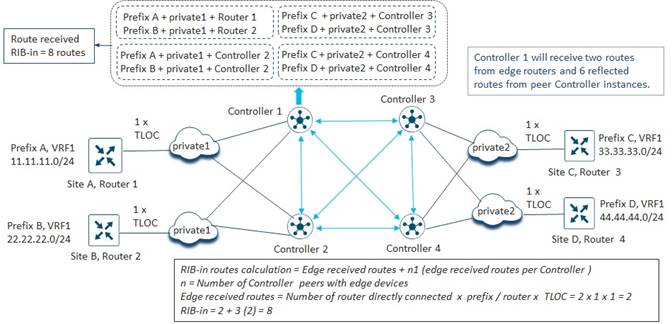
Here, the number of SD-WAN routers (Edge devices) peered with each SD-WAN Controller instance has been increased from one to two. As with our previous example network, each of the SD-WAN routers has a single TLOC and a single IPv4 unicast prefix.
Because of the symmetry of our example, we can use the simplified equation to determine the number of received routes (RIB-in table size) of each of the SD-WAN Controller instances as follows:
Received routes (RIB-in) calculation =
Edge received routes + (n x Edge received routes per SD-WAN Controller)
where:
n = Number of SD-WAN Controller peers with edge devices
This yields the following for each SD-WAN Controller:
Received routes (RIB-in) calculation for SD-WAN Controller =
2 Edge received route + (3 x 2 Edge received routes per SD-WAN Controller
peer) = 2 + (3 x 2) = 8 routes received
This highlights the effect of adding additional SD-WAN routers (Edge devices) peered with each SD-WAN Controller instance. Adding 2 additional SD-WAN routers (Edge devices), each with a single IPv4 unicast prefix and a single TLOC, to the example network above, increased the number of routes receives (RIB-in table size) by each SD-WAN Controller instance from 4 to 8. In other words, because the SD-WAN Controller instances reflect directly connected routes, adding 1 new SD-WAN router (Edge device) with 1 TLOC and 1 IPv4 unicast prefix does not result in just 1 additional route received on each SD-WAN Controller instance. In this example, 2 new IPv4 unicast routes were introduced through 2 different SD-WAN routers, each with a single TLOC. The result was the addition of 4 new received routes (RIB-in entries) per SD-WAN Controller instance.
Next, we turn to a slightly simpler example network to look at the effects of multiple WAN interfaces (multiple TLOCs) on received routes.
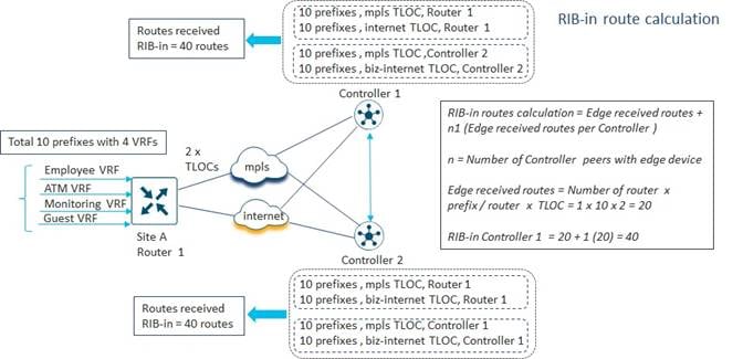
In the example above, we also have multiple IPv4 unicast prefixes – specifically 10 prefixes – resulting both from additional Service VPNs supported on the LAN side of the SD-WAN router (each of which will require the sending of at least one IPv4 prefix within OMP updates), as well as multiple IPv4 prefixes (resulting from multiple IPv4 subnet addresses) per Service VPN.
Again, we can use the following equation to determine the number of Edge received routes on SD-WAN Controller 1.
Edge received routes =
Number of routers with OMP sessions (directly connected) to the SD-WAN
Controller x Number of prefixes sent per router x Number of TLOCs per router
In the figure above if we calculate the Edge received routes for SD-WAN Controller 1 we get the following:
Edge received routes SD-WAN Controller 1 =
1 router (Router 1) directly connected to SD-WAN Controller 1 x
10 prefixes sent from Router 1 x
2 TLOCs on Router 1 (mpls & biz-internet TLOCs) = 1 x 10 x 2
= 20 Edge received routes on SD-WAN Controller 1
Likewise, we can run the same calculation for the Edge received routes for SD-WAN Controller 2.
Edge received routes SD-WAN Controller 2 =
1 router (Router 1) directly connected to SD-WAN Controller 1 x
10 prefixes sent from Router 1 x
2 TLOCs on Router 1 (mpls & biz-internet TLOCs)
= 1 x 10 x 2 = 20 Edge received routes on SD-WAN Controller 2
Because of the 2 TLOCs (mpls and biz-internet) each SD-WAN Controller instance will receive the 10 unicast IPv4 prefixes directly from the SD-WAN router (Edge device) via each TLOC, for a total of 20 Edge received routes.
We can then use our simplified equation to determine the total number of received routes (RIB-in table size) on SD-WAN Controller 1 as follows:
Received routes (RIB-in) calculation =
Edge received routes + (n x Edge received routes per SD-WAN Controller)
where:
n = Number of SD-WAN Controller peers with edge devices
This yields the following for SD-WAN Controller 1:
Received routes (RIB-in) calculation for SD-WAN Controller 1 =
20 Edge received route + (1 x 20 Edge received routes per SD-WAN
Controller peer) = 20 + (1 x 20) = 40 routes received
Running the same calculation yields the same answer for SD-WAN Controller 2:
Received routes (RIB-in) calculation for SD-WAN Controller 2 =
20 Edge received route + 1 x (20 Edge received routes per SD-WAN
Controller peer) = 20 + (1 x 20) = 40 routes received
Here we see the multiplicative effects both of having multiple TLOCs and of having each SD-WAN Controller instance reflecting directly connected routes to other SD-WAN Controller instances. In the example above, there are a total of 10 IPv4 unicast prefixes in the entire network. However, the number of routes received (and hence the RIB-in table size) by each SD-WAN Controller is four times that amount, 40 routes received.
If we take this example network further by adding an additional SD-WAN Controller instance which has no SD-WAN routers OMP-peered with the SD-WAN Controller instance, the network looks as follows.
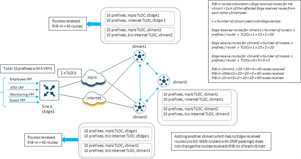
Again, we can use the following equation to determine the number of Edge received routes on each SD-WAN Controller.
Edge received routes =
Number of routers with OMP sessions (directly connected) to the SD-WAN
Controller x Number of prefixes sent per router x Number of TLOCs per router
In the figure above if we calculate the Edge received routes for SD-WAN Controller 1 we get the following:
Edge received routes SD-WAN Controller 1 =
1 router (Router 1) directly connected to SD-WAN Controller 1 x
10 prefixes sent from Router 1 x
2 TLOCs on Router 1 (mpls & biz-internet TLOCs)
= 1 x 10 x 2 = 20 Edge received routes on SD-WAN Controller 1
Likewise, we can run the same calculation for the Edge received routes for SD-WAN Controller 2.
Edge received routes SD-WAN Controller 2 =
1 router (Router 1) directly connected to SD-WAN Controller 2 x
10 prefixes sent from Router 1 x
2 TLOCs on Router 1 (mpls & biz-internet TLOCs)
= 1 x 10 x 2 = 20 Edge received routes on SD-WAN Controller 2
Finally, we can run the same calculation for the Edge received routes for SD-WAN Controller 3.
Edge received routes SD-WAN Controller 3 =
0 routers directly connected to SD-WAN Controller 3 x
0 prefixes sent from any routers x
0 TLOCs
= 0 x 0 x 0 = 0 Edge received routes on SD-WAN Controller 3
Since our SD-WAN Controller instances are no longer symmetric, in that they do not all have the same number of SD-WAN routers with the same number of TLOCs and the same number of prefixes per router, we cannot use our simplified equation to determine the total number of received routes (RIB-in table size) on each SD-WAN Controller. Instead, we use the following equation:
RIB-in received routes calculation =
Edge received routes for the SD-WAN Controller +
Sum of the reflected Edge received routes from each other SD-WAN Controller peer
This yields the following for SD-WAN Controller 1:
Received routes (RIB-in) calculation for SD-WAN Controller 1 =
20 Edge received routes +
20 reflected Edge received routes from SD-WAN Controller 2 +
0 reflected Edge received routes from SD-WAN Controller 3 =
20 + 20 + 0 = 40 routes received
Running the same calculation yields the same answer for SD-WAN Controller 2:
Received routes (RIB-in) calculation for SD-WAN Controller 2 =
20 Edge received routes +
20 reflected Edge received routes from SD-WAN Controller 1 +
0 reflected Edge received routes from SD-WAN Controller 3 =
20 + 20 + 0 = 40 routes received
Finally, running the same calculation again yields the same answer for SD-WAN Controller 3:
Received routes (RIB-in) calculation for SD-WAN Controller 3 =
0 Edge received routes +
20 reflected Edge received routes from SD-WAN Controller 1 +
20 reflected Edge received routes from SD-WAN Controller 2
= 0 + 20 + 20 = 40 routes received
As can be seen from these calculations, simply adding another SD-WAN Controller instance into the network – when the new SD-WAN Controller instance has no SD-WAN routers OMP-peered with it – will not change the received routes (RIB-in table size) of any of the SD-WAN Controller instances.
Note that all the previous calculations within this Appendix have assumed that the max-omp-sessions and tunnel-interface-level max-control-connections settings for the SD-WAN routers have been left at their default values of 2. In our final example, we will investigate the effects on routes receives (RIB-in) of changing these settings from 2 to 3.
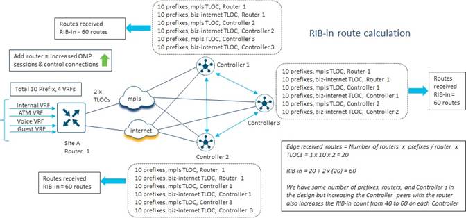
Again, we can use the following equation to determine the number of Edge received routes on each SD-WAN Controller.
Edge received routes =
Number of routers with OMP sessions (directly connected) to the SD-WAN
Controller x Number of prefixes sent per router x Number of TLOCs per router
In our new example, each SD-WAN Controller is symmetric in that the SD-WAN router has an OMP peering session with each of the 3 SD-WAN Controllers. Hence, if we calculate the Edge received routes for each SD-WAN Controller we get the following:
Edge received routes SD-WAN Controller =
1 router (Router 1) directly connected to each SD-WAN Controller x
10 prefixes sent from Router 1 x
2 TLOCs on Router 1 (mpls & biz-internet TLOCs)
= 1 x 10 x 2 = 20 Edge received routes on each SD-WAN Controller
We can then use our simplified equation to determine the total number of received routes (RIB-in table size) on each SD-WAN Controller as follows:
Received routes (RIB-in) calculation =
Edge received routes + (n x Edge received routes per SD-WAN Controller)
where:
n = Number of SD-WAN Controller peers with edge devices
This yields the following for each of the three SD-WAN Controller instances:
Received routes (RIB-in) calculation for SD-WAN Controller 1 =
20 Edge received route + (2 x 20 Edge received routes per SD-WAN
Controller peer)= 20 + (2 x 20) = 60 routes received
Received routes (RIB-in) calculation for SD-WAN Controller 2 =
20 Edge received route + (2 x 20 Edge received routes per SD-WAN
Controller peer) = 20 + (2 x 20) = 60 routes received
Received routes (RIB-in) calculation for SD-WAN Controller 3 =
20 Edge received route + (2 x 20 Edge received routes per SD-WAN
Controller peer)= 20 + (2 x 20) = 60 routes received
As we can see, increasing the max-omp-sessions and the tunnel-interface-level max-control-connections settings from the default of 2 to 3 has the effect of increasing the routes received (RIB-in table size) from 40 to 60 routes. Again, it should be highlighted that in the example network in the figure above, there are only 10 unicast IPv4 prefixes advertised by one SD-WAN router (Router 1). Because there are two TLOCS (mpls and biz-internet) on the SD-WAN router, the 10 IPv4 prefixes are advertised to each SD-WAN Controller to which the SD-WAN router is OMP-peered with, over each TLOC. This alone increases the Edge received routes by each SD-WAN Controller instance from 10 to 20 routes. In addition to this, each SD-WAN Controller now has two SD-WAN Controller peers, each of which have edge received routes from the SD-WAN router (Router 1). These edge received routes are reflected to the other two SD-WAN Controller instances. This accounts for the additional 40 received routes, for a total of 60 receive routes per SD-WAN Controller – which is also the RIB-in table size per SD-WAN Controller in our final example.
For larger SD-WAN deployments, the same basic logic of determining the “directly connected routes” or “edge received routes” from SD-WAN routers OMP-peered with a given SD-WAN Controller instance, and then adding the “reflected routes” from each other SD-WAN Controller which is peered with the SD-WAN Controller instance, can be used to determine the total received routes (RIB-in table size) for each SD-WAN Controller instance within an overlay.
Routes Sent (RIB-out) Calculations
The routes sent (RIB-out) calculations per SD-WAN Controller are somewhat dependent upon the fabric data plane topology (full-mesh or hub-and-spoke) as well as the nature of the centralized control policy used to implement a hub-and-spoke topology. More specifically, the routes sent (RIB-out) calculation for each specific SD-WAN Controller is also dependent upon whether the hub-and-spoke topology is implemented using TLOC rewrite policy, or whether the hub sites send a default route to the spoke sites, or some combination of both is implemented within the overlay.
Full-Mesh Fabric Data Plane Topology
In a full-mesh fabric data plane topology, all WAN Edge devices form SD-WAN tunnels to each other and send traffic directly to each other. In this topology, typically there is no filtering or altering of OMP routes or TLOCs, via centralized control policy deployed inbound or outbound on the SD-WAN Controller instances. Hence, in a full-mesh fabric data plane topology, SD-WAN Controller instances reflect edge received routes, as discussed in the previous section.
The following figure shows an example network which will be used to explain how the calculations for routes sent (RIB-out) for each SD-WAN Controller instance is performed.
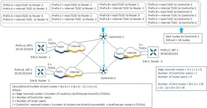
The routes sent (RIB-out) calculation for each SD-WAN Controller instance in a full-mesh topology consists of the following components:
● Edge routes received from SD-WAN routers that are OMP-peered with the SD-WAN Controller instance, which are then reflected to the other SD-WAN Controller instances within the overlay (since all SD-WAN Controller instances in an overlay are OMP-peered with each other). This can be expressed with the following equation:
a x b
where a = Edge received routes
= (Number of branch routers with OMP sessions to the SD-WAN Controller) x
(prefixes per router) x (TLOCs)
and b = Number of SD-WAN Controller peers to the given SD-WAN Controller instance
● Edge routes received from SD-WAN routers that are OMP-peered with the SD-WAN Controller instance, which are then reflected to other SD-WAN routers that are OMP-peered with the same SD-WAN Controller instance. This can be expressed with the following equation:
a x (n – 1)
where a = Edge received routes
= (number of routers OMP peered with the SD-WAN Controller instance) x
(prefixes per router) x (TLOCs)
and n = number of router peers to the given SD-WAN Controller instance
Note that a SD-WAN Controller instance will not reflect OMP routes sent from a given SD-WAN router back to the same router. For example, given there are 1,250 SD-WAN routers with OMP sessions to SD-WAN Controller 1, an OMP route / prefix sent to SD-WAN Controller 1 from one router will be reflected to the other 1,249 routers which are OMP-peered with SD-WAN Controller 1.
● The sum of the received routes from the other SD-WAN Controller instances (referred to as “SD-WAN Controller received routes”) within the overlay, which are then reflected by the SD-WAN Controller instance to any SD-WAN routers OMP-peered with the given SD-WAN Controller instance. This can be expressed with the following equation:
c x n
where c = (Number of routers not directly connected to the SD-WAN Controller
instance) x (prefixes per router) x (number of TLOCs per router)
and n = number of router peers to the given SD-WAN Controller instance
In the figure above, the example network consists of three sites, each consisting of a single SD-WAN router with two TLOCs. All three SD-WAN routers have OMP peering relationships with the two SD-WAN Controller instances in the network – SD-WAN Controller 1 and SD-WAN Controller 2. Each of the sites has a single IPv4 prefix which is advertised via OMP to the SD-WAN Controller instances.
We can calculate of the first component of routes sent (RIB-out) for SD-WAN Controller 1 as follows:
a x b
where a = Edge received routes
= (Number of branch routers with OMP sessions to SD-WAN Controller 1) x
(prefixes per router) x (TLOCs)
= 3 x 1 x 2 = 6 routes
and b = Number of SD-WAN Controller peers to SD-WAN Controller 1
= 1
a x b = 6 x 1 = 6 routes
We can calculate the second component of routes sent (RIB-out) for SD-WAN Controller 1 as follows:
a x (n – 1)
where a = Edge received routes
= (number of routers OMP peered with SD-WAN Controller 1) x
(prefixes per router) x (TLOCs)
= 3 x 1 x 2 = 6 routes
and n = number of router peers to the given SD-WAN Controller instance
= 3 routers peered with SD-WAN Controller 1
a x (n – 1) = 6 x (3 – 1) = 12 routes
Finally, we can calculate the third component of routes sent (RIB-out) for SD-WAN Controller 1 as follows:
c x n
where c = (Number of routers not directly connected to SD-WAN Controller 1) x
(prefixes per router) x (number of TLOCs per router)
= 0 x 1 x 2 = 0
and n = number of router peers to SD-WAN Controller 1
= 3 routers peered with SD-WAN Controller 1
c x n = 0 x 3 = 0 routes
Summing all three components gives us the total routes sent (size of the RIB-out table) for SD-WAN Controller 1 as follows:
(a x b) + (a x (n – 1)) + (c x n) = 6 + 12 + 0 = 18 routes
If we run the same calculations for SD-WAN Controller 2 in this example network we will find that SD-WAN Controller 2 also sends 18 routes. In other words, the number of routes sent – and therefore the size of the RIB-out table – for both SD-WAN Controller instances in this example network is 18 routes.
We can continue with a slightly more complex network example as shown in the figure below.
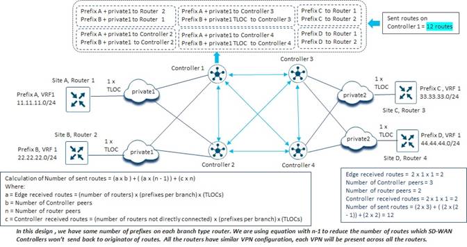
In the figure above, the example network now consists of four sites, each consisting of a single SD-WAN router with one TLOC. Two SD-WAN routers (SiteA Router 1 and SiteB Router 3) have OMP peering relationships with two SD-WAN Controller instances in the network – SD-WAN Controller 1 and SD-WAN Controller 2, and two SD-WAN routers (SiteC Router 3 and SiteD Router 4) have OMP peering relationships with the other two SD-WAN Controller instances in the network – SD-WAN Controller 3 and SD-WAN Controller 4. Each of the sites has a single IPv4 prefix which is advertised via OMP to the SD-WAN Controller instances.
We can calculate of the first component of routes sent (RIB-out) for SD-WAN Controller 1 as follows:
a x b
where a = Edge received routes
= (Number of branch routers with OMP sessions to SD-WAN Controller 1) x
(prefixes per router) x (TLOCs)
= 2 x 1 x 1 = 2 routes
and b = Number of SD-WAN Controller peers to SD-WAN Controller 1
= 3
a x b = 2 x 3 = 6 routes
We can calculate the second component of routes sent (RIB-out) for SD-WAN Controller 1 as follows:
a x (n – 1)
where a = Edge received routes
= (number of routers OMP peered with SD-WAN Controller 1) x
(prefixes per router) x (TLOCs)
= 2 x 1 x 1 = 2 routes
and n = number of router peers to SD-WAN Controller 1
= 2 routers peered with SD-WAN Controller 1
a x (n – 1) = 2 x (2 – 1) = 2 routes
Finally, we can calculate the third component of routes sent (RIB-out) for SD-WAN Controller 1 as follows:
c x n
where c = (Number of routers not directly connected to SD-WAN Controller 1) x
(prefixes per router) x (number of TLOCs per router)
= 2 x 1 x 1 = 2
and n = number of router peers to SD-WAN Controller 1
= 2 routers peered with SD-WAN Controller 1
c x n = 2 x 2 = 4 routes
Summing all three components gives us the total routes sent (size of the RIB-out table) for SD-WAN Controller 1 as follows:
(a x b) + (a x (n – 1)) + (c x n) = 6 + 2 + 4 = 12 routes
Again, if we run the same calculations for SD-WAN Controller 2 through SD-WAN Controller 4 in this example network we will find that the other SD-WAN Controller instances also sends 12 routes because of the symmetrical design of this network. In other words, the number of routes sent – and therefore the size of the RIB-out table – for all SD-WAN Controller instances in this example network is 12 routes.
Hub-and-Spoke Fabric Data Plane Topology
In a hub-and-spoke fabric data plane topology, spoke WAN Edge devices form SD-WAN tunnels to hub WAN Edge devices only. All spoke-to-spoke traffic is sent first to hub routers, which hairpin the traffic back to the destination spoke router. Hub-and-spoke topologies are typically implemented using one of the following methods:
● Use of centralized control policy to rewrite the TLOC through which each spoke OMP prefix / route is reachable. TLOC rewrite policy is generally deployed as an outbound centralized control policy – meaning that the TLOCs of the spoke prefixes are rewritten as the OMP routes are being sent outbound from the SD-WAN Controller instances to the specific spoke site SD-WAN routers to which the policy is applied. Using this method, the TLOC of the spoke router is replaced with one or more TLOCs which represent the hub routers. The specific spoke prefixes are still reflected by the SD-WAN Controller instances to each spoke router, but the TLOC through which the spoke prefixes are reachable has been changed to the hub routers.
● Use centralized control policy to filter out the spoke prefixes / routes from being reflected by the SD-WAN Controller instances to each router. Instead send only a default route (and optionally the hub prefixes / routes) reachable via the TLOCs of the hub routers. The spoke prefixes still need to be reflected to the hub routers in order for the hub routers to be able to route traffic back to the specific spoke, but not to the spoke routers. All spoke-to-spoke traffic is again sent to the hub routers due to the default route reachable via the hub router TLOCs. From there, since the hub routers have visibility to all spoke prefixes / routes, the traffic is hair-pinned back to the destination branch router.
Hub-and-Spoke Topology using TLOC Rewrite Policy
In a hub-and-spoke topology implemented using TLOC rewrite policy, the routes sent (RIB-out) calculation for each SD-WAN Controller instance consist of the following seven components:
● Edge routes received from SD-WAN routers (hub or spoke) that are OMP-peered with the SD-WAN Controller instance, which are then reflected to the other SD-WAN Controller instances within the overlay – since all SD-WAN Controller instances in an overlay are OMP-peered with each other. This can be expressed with the following equation:
a x b
where a = Edge received routes
= (Number of SD-WAN routers with OMP sessions to the SD-WAN Controller) x
(prefixes per router) x (TLOCs)
and b = Number of SD-WAN Controller peers to the given SD-WAN Controller instance
Note that centralized policy using TLOC re-write is generally applied outbound on SD-WAN Controller instances against the site-IDs of the spoke sites and the hub sites. Since SD-WAN Controller instances are not part of these site-IDs, the TLOC re-write policy does not apply to routes sent between SD-WAN Controller instances.
● Edge routes received from spoke SD-WAN routers that are OMP-peered with the SD-WAN Controller instance, which are then reflected to other spoke SD-WAN routers that are OMP-peered with the same SD-WAN Controller instance. This is similar to the full-mesh scenario, except that with TLOC rewrite policy, the TLOC through which the spoke prefix is reachable is replaced with one or more TLOCs of the hub routers. This can be expressed with the following equation:
a_spoke x t x (n_spoke – 1)
where a_spoke = Spoke edge received routes
= (number of spoke / branch routers OMP peered with the SD-WAN Controller
instance) x (prefixes per router) x (TLOCs)
and t = Number of hub TLOCs through which the spoke edge received routes will be
advertised to be available through
and n_spoke = number of spoke router peers to the given SD-WAN Controller instance
Note that a SD-WAN Controller instance will not reflect OMP routes sent from a given SD-WAN router back to the same router. For example, given there are two SD-WAN routers with OMP sessions to SD-WAN Controller 1, an OMP route / prefix sent to SD-WAN Controller 1 from one router will only be reflected to the other router which is OMP-peered with SD-WAN Controller 1.
The number of data center (hub) TLOCs through which the Edge received routes will be advertised to be available through depends on the design of the network and the centralized control policy. Specifically, the number of available hub TLOCs is dependent on the number of hub sites, the number of SD-WAN routers per hub site, and whether the specific SD-WAN router within the hub site has a TLOC which can be and is used in the re-write policy.
● Edge routes received from spoke SD-WAN routers that are OMP-peered with the SD-WAN Controller instance, which are then reflected to hub SD-WAN routers that are OMP-peered with the same SD-WAN Controller instance. It is assumed that TLOC rewrite policy does not apply to spoke routes sent to hub sites. This can be expressed with the following equation:
a_spoke x n_hub
where a_spoke = Spoke edge received routes
= (number of spoke / branch routers OMP peered with the SD-WAN Controller
instance) x (prefixes per router) x (TLOCs)
and n_hub = Number of hub routers OMP peered with the SD-WAN Controller instance
● Edge routes received from hub SD-WAN routers that are OMP-peered with the SD-WAN Controller instance, which are then reflected to spoke SD-WAN routers that are OMP-peered with the same SD-WAN Controller instance. This is similar to the previous component except that TLOC rewrite policy is assumed to not apply to hub routers. This can be expressed with the following equation:
a_hub x n_spoke
where a_hub = Hub edge received routes
= (number of hub routers OMP peered with the SD-WAN Controller instance) x
(prefixes per router) x (TLOCs)
and n_spoke = number of spoke router peers to the given SD-WAN Controller instance
● Next, we need to account for the spoke edge received routes from other SD-WAN Controller instances in the network which are reflected to the SD-WAN Controller instance and, in turn, reflected to the spoke SD-WAN routers OMP-peered with the SD-WAN Controller. Again, this is like the full-mesh scenario, except that with TLOC rewrite policy, the TLOC through which the spoke prefix is reachable is replaced with the TLOCs of the hub routers. This can be expressed with the following equation:
c_spoke x t x n_spoke
where c = number of spoke edge received routes from other SD-WAN Controller instances
which will be reflected. (For the example network this is the number of spoke
devices not peered with the SD-WAN Controller instance multiplied by the
number of TLOCs per device).
and t = Number of hub / data center TLOCs through which the spoke edge received
routes will be advertised to be available through
and n_spoke = number of spoke router peers to the given SD-WAN Controller instance
● Next, we need to account for the spoke edge received routes from other SD-WAN Controller instances in the network which are reflected to the SD-WAN Controller instance and, in turn, reflected to the hub SD-WAN routers OMP-peered with the SD-WAN Controller. Again, TLOC rewrite policy is assumed not to apply to hub routers. This can be expressed with the following equation:
c_spoke x n_hub
where c = number of spoke edge received routes from other SD-WAN Controller instances
and n_hub = number of hub router peers to the given SD-WAN Controller instance
● Next, we need to account for the hub edge received routes from other SD-WAN Controller instances in the network which are reflected to the SD-WAN Controller instance and, in turn, reflected to the both the hub and spoke SD-WAN routers OMP-peered with the SD-WAN Controller instance. Again, it is assumed that TLOC rewrite policy is not applied to hub routes. This can be expressed with the following equation:
d x n
where d = number of hub edge received routes from other SD-WAN Controllers which will
be reflected. (For the example network this is the number of hub devices
not peered with the SD-WAN Controller instance multiplied by the number of
TLOCs per device).
and n = number of router (hub and spoke) peers to the given SD-WAN Controller instance
The following figure shows an example network which will be used to explain how the calculations for routes sent (RIB-out) for each SD-WAN Controller instance is performed when a TLOC rewrite policy is implemented.
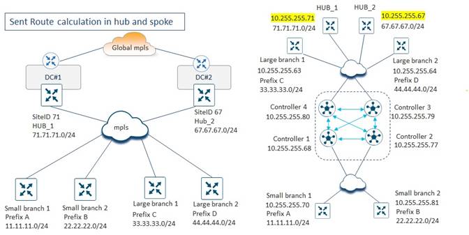
The example network in the figure above consists of two hub sites (Hub_1 and Hub_2), each with a single OMP prefix. There are a total of four spoke / branch sites – two large branches (Large branch 1 and Large branch 2) and two small branches (Small branch 1 and Small branch 2). To more effectively highlight the nuances of calculating the routes sent (RIB-out) in a hub-and-spoke topology implemented using TLOC rewrite policy, the small branches are shown to have OMP peering relationships to two SD-WAN Controller instances (SD-WAN Controller 1 and SD-WAN Controller 2), while the large branches and the hub sites are shown to have OMP peering relationships to two other SD-WAN Controller instances (SD-WAN Controller 3 and SD-WAN Controller 4).
We can calculate of the first component of routes sent (RIB-out) for SD-WAN Controller 1 as follows:
a x b
where a = Edge received routes
= (Number of SD-WAN routers OMP peered to SD-WAN Controller 1) x
(prefixes per router) x (TLOCs)
= 2 x 1 x 1 = 2 routes
and b = Number of SD-WAN Controller peers to SD-WAN Controller 1
= 3
a x b = 2 x 3 = 6 routes
We can calculate the second component of routes sent (RIB-out) for SD-WAN Controller 1 as follows:
a_spoke x t x (n_spoke – 1)
where a_spoke = Spoke edge received routes
= (number of spoke / branch routers OMP peered with SD-WAN Controller 1)
x (prefixes per router) x (TLOCs)
= 2 x 1 x 1 = 2 routes
and t = Number of hub TLOCs through which the spoke edge received routes will be
advertised to be available through
= 2
and n_spoke = number of spoke router peers to SD-WAN Controller 1
= 2
a_spoke x t x (n_spoke – 1) = 2 x 2 x (2 – 1) = 4 routes
We can calculate the third component of routes sent (RIB-out) for SD-WAN Controller 1 as follows:
a_spoke x n_hub
where a_spoke = Spoke edge received routes
= (number of spoke / branch routers OMP peered with SD-WAN Controller 1)
x (prefixes per router) x (TLOCs)
= 2 x 1 x 1 = 2 routes
and n_hub = Number of hub routers OMP peered with SD-WAN Controller 1
= 0
a_spoke x n_hub = 2 x 0 = 0 routes
We can calculate the fourth component of routes sent (RIB-out) for SD-WAN Controller 1 as follows:
a_hub x n_spoke
where a_hub = Hub edge received routes
= (number of hub routers OMP peered with SD-WAN Controller 1) x
(prefixes per router) x (TLOCs)
= 0
and n_spoke = number of spoke router peers to SD-WAN Controller 1
= 2
a_hub x n_spoke = 0 x 2 = 0 routes
We can calculate the fifth component of routes sent (RIB-out) for SD-WAN Controller 1 as follows:
c_spoke x t x n_spoke
where c = number of spoke edge received routes from other SD-WAN Controller instances
which will be reflected
= 1 prefix x 1 TLOC from Large branch 1 + 1 prefix x 1 TLOC from Large Branch 2
= 2 routes
and t = Number of hub / data center TLOCs through which the spoke edge received
routes will be advertised to be available through
= 2
and n_spoke = number of spoke router peers to SD-WAN Controller 1
= 2
c_spoke x t x n_spoke = 2 x 2 x 2 = 8 routes
We can calculate the sixth component of routes sent (RIB-out) for SD-WAN Controller 1 as follows:
c_spoke x n_hub
where c = number of spoke edge received routes from other SD-WAN Controller instances
which will be reflected
= 1 prefix x 1 TLOC from Large branch 1 + 1 prefix x 1 TLOC from Large Branch 2
= 2 routes
and n_hub = number of hub router peers to SD-WAN Controller 1
= 0
c_spoke x n_hub = 2 x 0 = 0 routes
Finally, we can calculate the seventh component of routes sent (RIB-out) for SD-WAN Controller 1 as follows:
d x n
where d = number of hub edge received routes from other SD-WAN Controllers which will
be reflected
= 1 prefix x 1 TLOC from Hub_1 + 1 prefix x 1 TLOC from Hub_2
= 2 routes
and n = number of router (hub and spoke) peers to the given SD-WAN Controller instance
= 2
d x n = 2 x 2 = 4 routes
Summing all seven components gives us the total routes sent (size of the RIB-out table) for SD-WAN Controller 1 as follows:
= 6 + 4 + 0 + 0 + 8 + 0 + 4 = 22 routes
If we run the same calculations for SD-WAN Controller 2 in this example network we will find that SD-WAN Controller 2 also sends 22 routes. In other words, the number of routes sent – and therefore the size of the RIB-out table – for both SD-WAN Controller instances which have OMP peering with the Small branch routers in this example network is 22 routes.
However, the number of routes sent (size of the RIB-out table) by the SD-WAN Controller instances peered with the Large branch and hub routers will be different, as shown in the following figure.
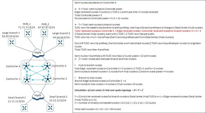
We can calculate of the first component of routes sent (RIB-out) for SD-WAN Controller 4 as follows:
a x b
where a = Edge received routes
= (Number of SD-WAN routers OMP peered to SD-WAN Controller 4) x
(prefixes per router) x (TLOCs)
= 4 x 1 x 1 = 4 routes
and b = Number of SD-WAN Controller peers to SD-WAN Controller 4
= 3
a x b = 4 x 3 = 12 routes
We can calculate the second component of routes sent (RIB-out) for SD-WAN Controller 4 as follows:
a_spoke x t x (n_spoke – 1)
where a_spoke = Spoke edge received routes
= (number of spoke / branch routers OMP peered with SD-WAN
Controller 4) x
(prefixes per router) x (TLOCs)
= 2 x 1 x 1 = 2 routes
and t = Number of hub TLOCs through which the spoke edge received routes will be
advertised to be available through
= 2
and n_spoke = number of spoke router peers to SD-WAN Controller 4
= 2
a_spoke x t x (n_spoke – 1) = 2 x 2 x (2 – 1) = 4 routes
We can calculate the third component of routes sent (RIB-out) for SD-WAN Controller 4 as follows:
a_spoke x n_hub
where a_spoke = Spoke edge received routes
= (number of spoke / branch routers OMP peered with SD-WAN Controller 4)
x (prefixes per router) x (TLOCs)
= 2 x 1 x 1 = 2 routes
and n_hub = Number of hub routers OMP peered with SD-WAN Controller 4
= 2
a_spoke x n_hub = 2 x 2 = 4 routes
We can calculate the fourth component of routes sent (RIB-out) for SD-WAN Controller 4 as follows:
a_hub x n_spoke
where a_hub = Hub edge received routes
= (number of hub routers OMP peered with SD-WAN Controller 4) x
(prefixes per router) x (TLOCs)
= 2 x 1 x 1 = 2
and n_spoke = number of spoke router peers to SD-WAN Controller 4
= 2
a_hub x n_spoke = 2 x 2 = 4 routes
We can calculate the fifth component of routes sent (RIB-out) for SD-WAN Controller 4 as follows:
c_spoke x t x n_spoke
where c = number of spoke edge received routes from other SD-WAN Controller instances
which will be reflected
= 1 prefix x 1 TLOC from Small branch 1 + 1 prefix x 1 TLOC from Small Branch 2
= 2 routes
and t = Number of hub / data center TLOCs through which the spoke edge received
routes will be advertised to be available through
= 2
and n_spoke = number of spoke router peers to SD-WAN Controller 4
= 2
c_spoke x t x n_spoke = 2 x 2 x 2 = 8 routes
We can calculate the sixth component of routes sent (RIB-out) for SD-WAN Controller 4 as follows:
c_spoke x n_hub
where c = number of spoke edge received routes from other SD-WAN Controller instances
which will be reflected
= 1 prefix x 1 TLOC from Small branch 1 + 1 prefix x 1 TLOC from Small Branch 2
= 2 routes
and n_hub = number of hub router peers to SD-WAN Controller 4
= 2
c_spoke x n_hub = 2 x 2 = 4 routes
Finally, we can calculate the seventh component of routes sent (RIB-out) for SD-WAN Controller 4 as follows:
d x n
where d = number of hub edge received routes from other SD-WAN Controllers which will
be reflected
= 0 routes
and n = number of router (hub and spoke) peers to the given SD-WAN Controller instance
= 2
d x n = 0 x 2 = 0 routes
Summing all seven components gives us the total routes sent (size of the RIB-out table) for SD-WAN Controller 4 as follows:
= 12 + 4 + 4 + 4 + 8 + 4 + 0 = 36 routes
If we run the same calculations for SD-WAN Controller 3 in this example network we will find that SD-WAN Controller 3 also sends 36 routes. In other words, the number of routes sent – and therefore the size of the RIB-out table – for both SD-WAN Controller instances which have OMP peering with the Large branch and hub routers in this example network is 36 routes.
Hub-and-Spoke Topology using Default Route Policy
In a hub-and-spoke topology implemented by sending a default route from the hub sites and filtering out branch prefixes from being sent to the branches, the routes sent (RIB-out) calculation for each SD-WAN Controller instance consist of the following five components:
● Edge routes received from SD-WAN routers (hub or spoke) that are OMP-peered with the SD-WAN Controller instance, which are then reflected to the other SD-WAN Controller instances within the overlay – since all SD-WAN Controller instances in an overlay are OMP-peered with each other. This can be expressed with the following equation:
a x b
where a = Edge received routes
= (Number of SD-WAN routers with OMP sessions to the SD-WAN Controller) x
(prefixes per router) x (TLOCs)
and b = Number of SD-WAN Controller peers to the given SD-WAN Controller instance
Note that centralized control policy that is used to send a default route from hub sites and filter out spoke prefixes from being sent to other spoke sites is generally applied outbound on SD-WAN Controller instances against the site-IDs of the spoke sites and the hub sites. Since SD-WAN Controller instances are not part of these site-IDs, the policy does not apply to spoke routes sent between SD-WAN Controller instances.
● Edge routes received from spoke SD-WAN routers that are OMP-peered with the SD-WAN Controller instance, which are then reflected to hub SD-WAN routers that are OMP-peered with the same SD-WAN Controller instance. This can be expressed with the following equation:
a_spoke x n_hub
where a_spoke = Spoke edge received routes
= (number of spoke / branch routers OMP peered with the SD-WAN Controller
instance) x (prefixes per router) x (TLOCs)
and n_hub = Number of hub routers OMP peered with the SD-WAN Controller instance
● Edge routes (including the default route) received from hub SD-WAN routers that are OMP-peered with the SD-WAN Controller instance, which are then reflected to spoke SD-WAN routers that are OMP-peered with the same SD-WAN Controller instance. This can be expressed with the following equation:
a_hub x n_spoke
where a_hub = Hub edge received routes
= (number of hub routers OMP peered with the SD-WAN Controller instance) x
(prefixes per router + default route) x (TLOCs)
and n_spoke = number of spoke router peers to the given SD-WAN Controller instance
● Next, we need to account for the spoke edge received routes from other SD-WAN Controller instances in the network which are reflected to the SD-WAN Controller instance and, in turn, reflected to the hub SD-WAN routers OMP-peered with the SD-WAN Controller. This can be expressed with the following equation:
c_spoke x n_hub
where c = number of spoke edge received routes from other SD-WAN Controller instances
which will be reflected. (For the example network this is the number of spoke
devices not peered with the SD-WAN Controller instance multiplied by the
number of TLOCs per device).
and n_hub = number of hub router peers to the given SD-WAN Controller instance
● Finally, we need to account for the hub edge received routes from other SD-WAN Controller instances in the network which are reflected to the SD-WAN Controller instance and, in turn, reflected to the spoke SD-WAN routers OMP-peered with the SD-WAN Controller instance. This can be expressed with the following equation:
d x n_spoke
where d = number of hub edge received routes from other SD-WAN Controller instances
which will be reflected. (For the example network this is the number of hub
devices not peered with the SD-WAN Controller instance multiplied by the
number of TLOCs per device).
and n_spoke = number of spoke router peers to the given SD-WAN Controller instance
Note that with this design, the centralized data policy is assumed to filter out prefixes from Data Center (Hub) Sites from being sent to other Data Center (Hub) Sites. Traffic between Data Center (Hub) Sites is assumed to use the MPLS backbone with the Bank of the Earth design, rather than using an SD-WAN tunnel.
The same example network, repeated in the figure below, can be used to demonstrate how to calculate routes sent (RIB-out) for each SD-WAN Controller instance when a hub-and-spoke topology is implemented using a centralized control policy which filters spoke / branch routes from being sent to other spoke / branch sites (but not data center / hub sites) and also sends a default route along with the data center / hub prefixes to the branch sites.
As before, the example network above consists of two hub sites (Hub_1 and Hub_2), each with a single OMP prefix. There are a total of four spoke / branch sites – two large branches (Large branch 1 and Large branch 2) and two small branches (Small branch 1 and Small branch 2). To more effectively highlight the nuances of calculating the routes sent (RIB-out) in a hub-and-spoke topology implemented using TLOC rewrite policy, the small branches are shown to have OMP peering relationships to two SD-WAN Controller instances (SD-WAN Controller 1 and SD-WAN Controller 2), while the large branches and the hub sites are shown to have OMP peering relationships to two other SD-WAN Controller instances (SD-WAN Controller 3 and SD-WAN Controller 4).
We can calculate of the first component of routes sent (RIB-out) for SD-WAN Controller 1 as follows:
a x b
where a = Edge received routes
= (Number of SD-WAN routers OMP peered to SD-WAN Controller 1) x
(prefixes per router) x (TLOCs)
= 2 x 1 x 1 = 2 routes
and b = Number of SD-WAN Controller peers to SD-WAN Controller 1
= 3
a x b = 2 x 3 = 6 routes
We can calculate the second component of routes sent (RIB-out) for SD-WAN Controller 1 as follows:
a_spoke x n_hub
where a_spoke = Spoke edge received routes
= (number of spoke / branch routers OMP peered with SD-WAN Controller 1)
x (prefixes per router) x (TLOCs)
= 2 x 1 x 1 = 2 routes
and n_hub = Number of hub routers OMP peered with SD-WAN Controller 1
= 0
a_spoke x n_hub = 2 x 0 = 0 routes
We can calculate the third component of routes sent (RIB-out) for SD-WAN Controller 1 as follows:
a_hub x n_spoke
where a_hub = Hub edge received routes
= (number of hub routers OMP peered with SD-WAN Controller 1) x
(prefixes per router + default route) x (TLOCs)
= 0
and n_spoke = number of spoke router peers to SD-WAN Controller 1
= 2
a_hub x n_spoke = 0 x 2 = 0 routes
We can calculate the fourth component of routes sent (RIB-out) for SD-WAN Controller 1 as follows:
c_spoke x n_hub
where c = number of spoke edge received routes from other SD-WAN Controller instances
which will be reflected
= 1 prefix x 1 TLOC from Large branch 1 + 1 prefix x 1 TLOC from Large branch 2
= 2 routes
and n_hub = number of hub router peers to SD-WAN Controller 1
= 0
c_spoke x n_hub = 2 x 0 = 0 routes
Finally, we can calculate the fifth component of routes sent (RIB-out) for SD-WAN Controller 1 as follows:
d x n_spoke
where d = number of hub edge received routes (including the default) from other SD-WAN
Controllers which will be reflected
= 2 prefixes x 1 TLOC from Hub_1 + 2 prefixes x 1 TLOC from Hub_2
= 4 routes
and n_spoke = number of spoke routers peers to SD-WAN Controller 1
= 2
d x n_spoke = 2 x 4 = 8 routes
Summing all five components gives us the total routes sent (size of the RIB-out table) for SD-WAN Controller 1 as follows:
= 6 + 0 + 0 + 0 + 8 = 14 routes
If we run the same calculations for SD-WAN Controller 2 in this example network we will find that SD-WAN Controller 2 also sends 14 routes. In other words, the number of routes sent – and therefore the size of the RIB-out table – for both SD-WAN Controller instances which have OMP peering with the Small branch routers in this example network is 14 routes.
However, the number of routes sent (size of the RIB-out table) by the SD-WAN Controller instances peered with the Large branch and hub routers (SD-WAN Controller 3 and SD-WAN Controller 4) will be different.
We can calculate of the first component of routes sent (RIB-out) for SD-WAN Controller 4 as follows:
a x b
where a = Edge received routes
= ((Number of spoke routers OMP peered to SD-WAN Controller 4) x
(prefixes per spoke router including the default route) x (TLOCs)) +
((number of hub routers OMP peered to SD-WAN Controller 4) x
(prefixes per hub router) x (TLOCs))
= (2 x 1 x 1) + (2 x 2 x 1) = 6 routes
and b = Number of SD-WAN Controller peers to SD-WAN Controller 4
= 3
a x b = 6 x 3 = 18 routes
We can calculate the second component of routes sent (RIB-out) for SD-WAN Controller 4 as follows:
a_spoke x n_hub
where a_spoke = Spoke edge received routes
= (number of spoke / branch routers OMP peered with SD-WAN
Controller 4) x
(prefixes per router) x (TLOCs)
= 2 x 1 x 1 = 2 routes
and n_hub = Number of hub routers OMP peered with SD-WAN Controller 4
= 2
a_spoke x n_hub = 2 x 2 = 4 routes
We can calculate the third component of routes sent (RIB-out) for SD-WAN Controller 4 as follows:
a_hub x n_spoke
where a_hub = Hub edge received routes
= (number of hub routers OMP peered with SD-WAN Controller 4) x
(prefixes per router including the default route) x (TLOCs)
= 2 x 2 x 1 = 4
and n_spoke = number of spoke router peers to SD-WAN Controller 4
= 2
a_hub x n_spoke = 4 x 2 = 8 routes
We can calculate the fourth component of routes sent (RIB-out) for SD-WAN Controller 4 as follows:
c_spoke x n_hub
where c = number of spoke edge received routes from other SD-WAN Controller instances
which will be reflected
= 1 prefix x 1 TLOC from Large branch 1 + 1 prefix x 1 TLOC from Large branch 2
= 2 routes
and n_hub = number of hub router peers to SD-WAN Controller 1
= 2
c_spoke x n_hub = 2 x 2 = 4 routes
Finally, we can calculate the fifth component of routes sent (RIB-out) for SD-WAN Controller 4 as follows:
d x n_spoke
where d = number of hub edge received routes (including the default) from other SD-WAN
Controllers which will be reflected = 0 routes
and n_spoke = number of spoke router peers to SD-WAN Controller 4 = 4
d x n_spoke = 0 x 4 = 0 routes
Summing all five components gives us the total routes sent (size of the RIB-out table) for SD-WAN Controller 4 as follows:
= 18 + 4 + 8 + 4 + 0 = 34 routes
Again, if we run the same calculations for SD-WAN Controller 3 in this example network we will find that SD-WAN Controller 3 also sends 34 routes. In other words, the number of routes sent – and therefore the size of the RIB-out table – for both SD-WAN Controller instances which have OMP peering with the Large branch routers and Hub routers in this example network is 34 routes.
Edge Device Another term for an SD-WAN router
SD-WAN Router A router which participates in the Cisco Catalyst SD-WAN overlay
WAN Wide Area Network
WAN Edge Device Another term for an SD-WAN router
For comments and suggestions about this guide and related guides, join the discussion on Cisco Community at https://cs.co/en-cvds.