- Preface
- Cisco Video Surveillance Storage System Component Overview
- Unpacking and Preparing Components
- Rack Mounting Components
- Cabling & Power-up Procedures
- Field-Replaceable Units
- CPS-SS-4RU Technical Specifications
- CIVS-SS-4RU-84000 Technical Specifications
- CPS-SS-2RU Technical Specifications
- CPS-SS-4RU-EX Technical Specifications
- Index
Cisco Video Surveillance Storage System Hardware Installation Guide
Bias-Free Language
The documentation set for this product strives to use bias-free language. For the purposes of this documentation set, bias-free is defined as language that does not imply discrimination based on age, disability, gender, racial identity, ethnic identity, sexual orientation, socioeconomic status, and intersectionality. Exceptions may be present in the documentation due to language that is hardcoded in the user interfaces of the product software, language used based on RFP documentation, or language that is used by a referenced third-party product. Learn more about how Cisco is using Inclusive Language.
- Updated:
- March 2, 2012
Chapter: Rack Mounting Components
Rack Mounting Components
This chapter describes the installation procedures for Cisco Video Surveillance Storage System components. The CPS-SS-4RU and CPS-SS-4RU-EX components follow a similar set of install steps.
•![]() Rack Mounting the CPS-SS-4RU and CPS-SS-4RU-EX
Rack Mounting the CPS-SS-4RU and CPS-SS-4RU-EX
Rack Mounting the CPS-SS-4RU and CPS-SS-4RU-EX
The CPS-SS-4RU and CPS-SS-4RU-EX components follow a similar set of installation steps.
Preparing the Mounting Rails
The rack-mount system consists of left and right rail assemblies.

Step 1 ![]() Adjust the rail length by loosening the four screws holding the rear mount in place and sliding the mount out until it is the correct length. Do not retighten the screws yet.
Adjust the rail length by loosening the four screws holding the rear mount in place and sliding the mount out until it is the correct length. Do not retighten the screws yet.
Figure 3-1 Adjusting the Rack-Mount Rails
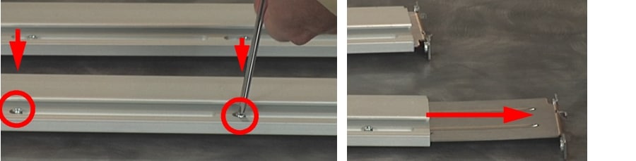
Step 2 ![]() Hook the front bracket hooks on each rail into the square holes in the rack at the proper level, then loosely attach the two front screws to hold each rail in place.
Hook the front bracket hooks on each rail into the square holes in the rack at the proper level, then loosely attach the two front screws to hold each rail in place.
Figure 3-2 Attaching the Mounting Rails in Front
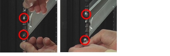
Step 3 ![]() Connect the back end of each rail to the rack by loosely attaching the two rear screws holding each rail in place.
Connect the back end of each rail to the rack by loosely attaching the two rear screws holding each rail in place.
Figure 3-3 Attaching the Mounting Rails in Back
Step 4 ![]() Retighten the screws that you loosened in Step 1 to hold the rear mount in place on each rail.
Retighten the screws that you loosened in Step 1 to hold the rear mount in place on each rail.
The mounting rails are now ready to receive the unit.
Mounting the Chassis into the Rack
The main chassis has large, keyed grooves in the extruded side plates. These are designed so that the rack-mount assemblies attached to the rack (in the previous procedures) can slide into these grooves and support the chassis.
Step 1 ![]() Ground any electrostatic charge from your person by touching a metal part of the rack.
Ground any electrostatic charge from your person by touching a metal part of the rack.
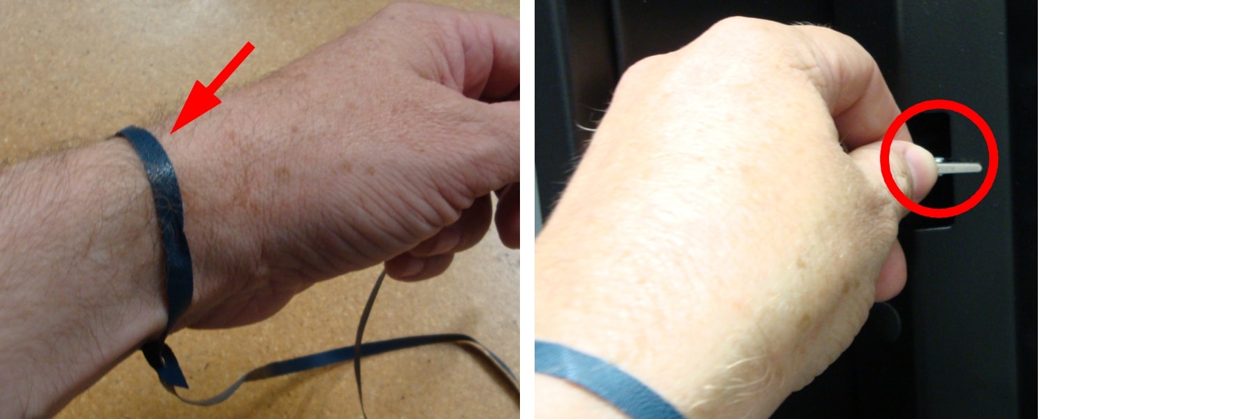
Step 2 ![]() Attach one end of the disposable anti-static wrist-strap to a metal part of the rack. Wrap the other end around your wrist. Both people lifting the unit should do this.
Attach one end of the disposable anti-static wrist-strap to a metal part of the rack. Wrap the other end around your wrist. Both people lifting the unit should do this.
Figure 3-4 Putting On and Attaching the Anti-Static Wrist-Strap
 |
Warning |
Step 3 ![]() With the help of a second person, carefully lift the unit so that the grooves in the side of the chassis line up with the mounting rails on the rack.
With the help of a second person, carefully lift the unit so that the grooves in the side of the chassis line up with the mounting rails on the rack.
Step 4 ![]() Carefully slide the unit onto the mounting rails, leaving a few inches between the front of the unit and the front of the rack.
Carefully slide the unit onto the mounting rails, leaving a few inches between the front of the unit and the front of the rack.
Figure 3-5 Sliding the Unit Onto the Mounting Rails
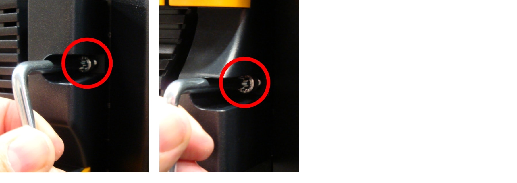
Step 5 ![]() While still supporting the unit from below, tighten the mounting rail screws at the front of each rail.
While still supporting the unit from below, tighten the mounting rail screws at the front of each rail.
Figure 3-6 Tightening the Front Mounting Rail Screws
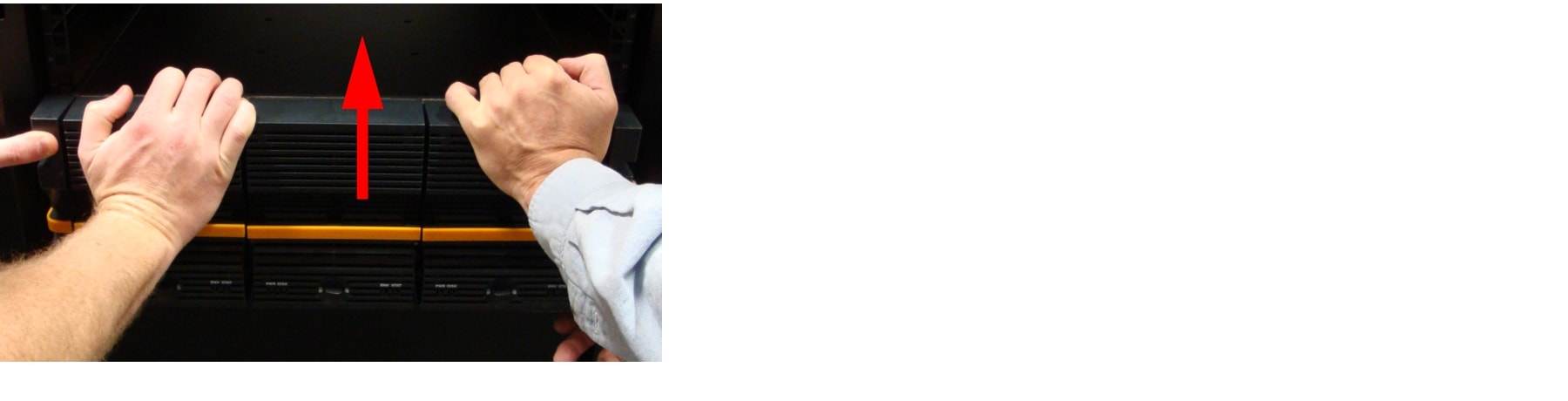
Step 6 ![]() Slide the unit the rest of the way into the rack so that the mounting ears sit against the rack.
Slide the unit the rest of the way into the rack so that the mounting ears sit against the rack.
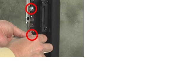
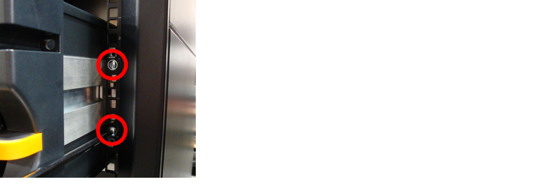
Step 7 ![]() Tightly bolt the front of the unit to the rack.
Tightly bolt the front of the unit to the rack.
Figure 3-7 Bolting the CPS-SS-4RU (Left) or CPS-SS-4RU-EX (Right) in Place
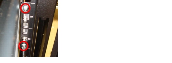
Step 8 ![]() Tighten the mounting rail screws at the back of each rail.
Tighten the mounting rail screws at the back of each rail.
Figure 3-8 Tightening the Rear Mounting Rail Screws
Restoring the Rear Modules
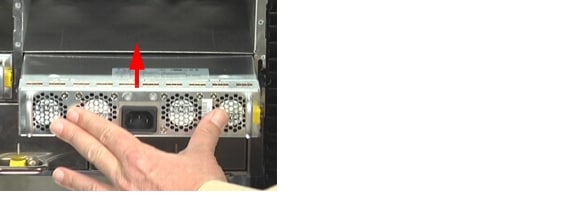
Step 1 ![]() Insert the two Power Supply Units (PSUs) into the back of the unit:
Insert the two Power Supply Units (PSUs) into the back of the unit:
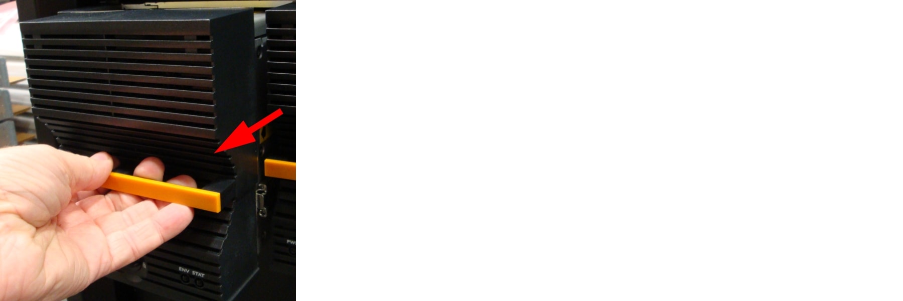
a. ![]() Make sure that the PSU is right-side up. The yellow spring lock tab should be on the right side.
Make sure that the PSU is right-side up. The yellow spring lock tab should be on the right side.
b. ![]() Insert the PSU into the slot and carefully slide it back until the spring lock tab clicks into place.
Insert the PSU into the slot and carefully slide it back until the spring lock tab clicks into place.
Figure 3-9 Inserting the PSU
c. ![]() Repeat Step 1 a and b for the second PSU.
Repeat Step 1 a and b for the second PSU.

Note ![]() Do not connect the power cords to the PSUs at this time.
Do not connect the power cords to the PSUs at this time.
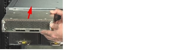
Step 2 ![]() Insert the RAID Controllers or Expansion Controllers into the back of the unit.
Insert the RAID Controllers or Expansion Controllers into the back of the unit.
a. ![]() Make sure that the RAID Controller or Expansion Controller is right side up. The yellow spring lock tab should be on the right side.
Make sure that the RAID Controller or Expansion Controller is right side up. The yellow spring lock tab should be on the right side.
b. ![]() Insert the RAID Controller or Expansion Controller into the slot and slide it back until the spring lock tab clicks into place.
Insert the RAID Controller or Expansion Controller into the slot and slide it back until the spring lock tab clicks into place.
Figure 3-10 Inserting the RAID Controller
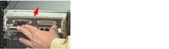
Figure 3-11 Inserting the Expansion Controller on the CPS-SS-4RU-EX
c. ![]() Repeat Step 2 a and b for the second RAID Controller/Expansion Controller.
Repeat Step 2 a and b for the second RAID Controller/Expansion Controller.
Loading Disk Drives
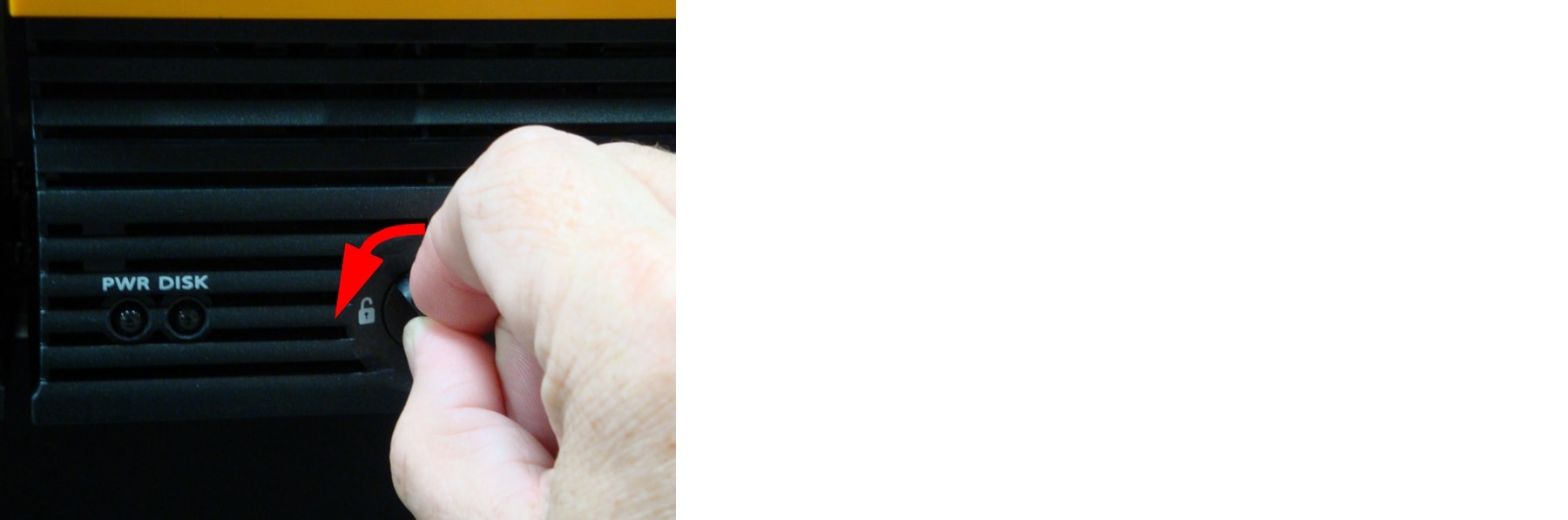
Step 1 ![]() Turn the drawer lock counter-clockwise to unlock the left drive drawer.
Turn the drawer lock counter-clockwise to unlock the left drive drawer.
Figure 3-12 Unlocking the Drive Drawer
Step 2 ![]() Carefully slide the drawer all the way out until the side rail locking tab clicks into place.
Carefully slide the drawer all the way out until the side rail locking tab clicks into place.
Figure 3-13 Sliding the Drive Drawer Out
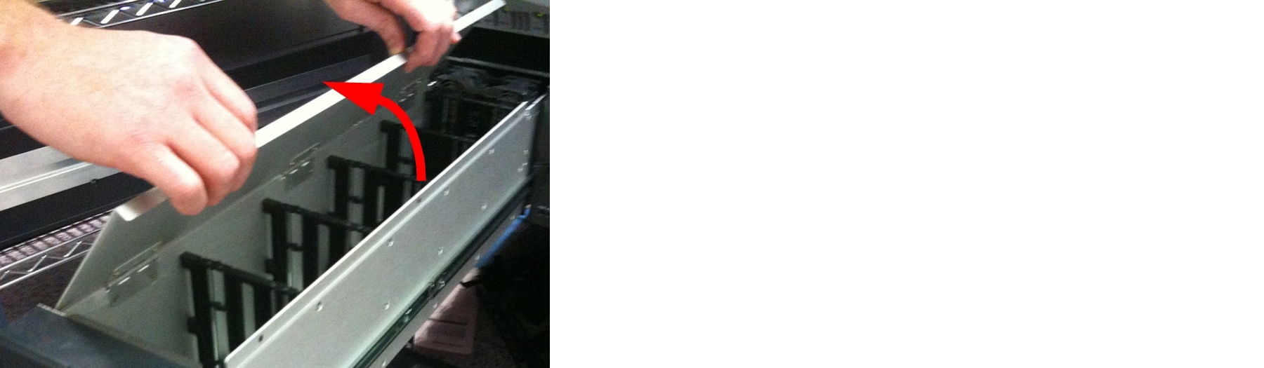
Step 3 ![]() For CPS-SS-4RU or CPS-SS-4RU-EX units, open the drive drawer lid.
For CPS-SS-4RU or CPS-SS-4RU-EX units, open the drive drawer lid.
Figure 3-14 Opening the Drive Drawer Lid
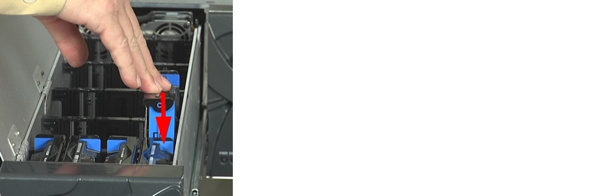
Step 4 ![]() Using the drive guides to help you orient the disks, carefully load each disk drive into a drive slot. Make sure that each disk is fully seated and that the drive ejection handles are flat against each drive.
Using the drive guides to help you orient the disks, carefully load each disk drive into a drive slot. Make sure that each disk is fully seated and that the drive ejection handles are flat against each drive.
Figure 3-15 Loading a Disk Drive Into a Unit
Note ![]() You can mix SAS and SATA drives in the same drive drawer, but it is recommended that all SAS drives are loaded towards the front of the drawer, with the SATA drives behind the SAS drives.
You can mix SAS and SATA drives in the same drive drawer, but it is recommended that all SAS drives are loaded towards the front of the drawer, with the SATA drives behind the SAS drives.
Step 5 ![]() Close the drive drawer lid.
Close the drive drawer lid.
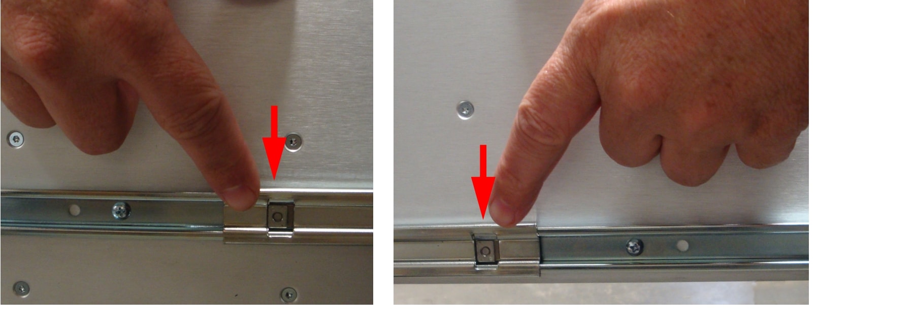
Step 6 ![]() Press the latches on either side of the drive drawer to disengage the drawer, then carefully slide the drawer back into the unit, making sure that it is flush with the rest of the front panel.
Press the latches on either side of the drive drawer to disengage the drawer, then carefully slide the drawer back into the unit, making sure that it is flush with the rest of the front panel.
Figure 3-16 Disengaging the Drawer Side Rail Latches
Step 7 ![]() Turn the drawer lock clockwise to lock the drawer into place.
Turn the drawer lock clockwise to lock the drawer into place.
Step 8 ![]() Repeat Step 1 through Step 7 for the other drive drawers.
Repeat Step 1 through Step 7 for the other drive drawers.
 Feedback