- Preface
- Cisco Video Surveillance Storage System Component Overview
- Unpacking and Preparing Components
- Rack Mounting Components
- Cabling & Power-up Procedures
- Field-Replaceable Units
- CPS-SS-4RU Technical Specifications
- CIVS-SS-4RU-84000 Technical Specifications
- CPS-SS-2RU Technical Specifications
- CPS-SS-4RU-EX Technical Specifications
- Index
Cisco Video Surveillance Storage System Hardware Installation Guide
Bias-Free Language
The documentation set for this product strives to use bias-free language. For the purposes of this documentation set, bias-free is defined as language that does not imply discrimination based on age, disability, gender, racial identity, ethnic identity, sexual orientation, socioeconomic status, and intersectionality. Exceptions may be present in the documentation due to language that is hardcoded in the user interfaces of the product software, language used based on RFP documentation, or language that is used by a referenced third-party product. Learn more about how Cisco is using Inclusive Language.
- Updated:
- March 2, 2012
Chapter: Cabling & Power-up Procedures
Cabling & Power-up Procedures
This section describes how to connect the communication, SAS, and power cables to the Cisco Video Surveillance Storage System components, and how to power them up. It includes the following sections:
•![]() Attaching Communication and Expansion Cables
Attaching Communication and Expansion Cables
Attaching Communication and Expansion Cables
CPS-SS-4RU
Connect all necessary communication cables to the RAID Controller (or Controllers) on the rear of the unit:
•![]() Connect the unit to your local area network (LAN) by attaching a CAT 5 or CAT 6 Ethernet cable to the management port (MGMT for CPS-SS-4RU; This enables you to access the unit's graphical user interface (GUI).
Connect the unit to your local area network (LAN) by attaching a CAT 5 or CAT 6 Ethernet cable to the management port (MGMT for CPS-SS-4RU; This enables you to access the unit's graphical user interface (GUI).
•![]() Connect the unit to your Host (server) by attaching fiber-optic cables to the Fibre Channel ports (Host 0 and/or Host 1).
Connect the unit to your Host (server) by attaching fiber-optic cables to the Fibre Channel ports (Host 0 and/or Host 1).
•![]() If you are connecting a CPS-SS-4RU-EX to your unit, attach SAS cables to the SAS ports (EXP 0 and EXP 1 on CPS-SS-4RU). Connect the other ends of the SAS cables to the CPS-SS-4RU-EX's SAS ports (EXP IN 0 and EXP IN 1).
If you are connecting a CPS-SS-4RU-EX to your unit, attach SAS cables to the SAS ports (EXP 0 and EXP 1 on CPS-SS-4RU). Connect the other ends of the SAS cables to the CPS-SS-4RU-EX's SAS ports (EXP IN 0 and EXP IN 1).
CPS-SS-4RU-EX
The CPS-SS-4RU-EX requires another Cisco Video Surveillance Storage System unit to provide RAID functionality and host/network connectivity to the CPS-SS-4RU-EX. The CPS-SS-4RU-EX should be mounted in the same rack as the unit to which it is to be connected or in an immediately adjacent rack (see Preparing the Site).
Using the supplied SAS cables, attach the CPS-SS-4RU-EX to the main storage unit as follows:
Step 1 ![]() Insert one SAS cable into each SAS port on the first RAID Controller in the main storage unit.
Insert one SAS cable into each SAS port on the first RAID Controller in the main storage unit.
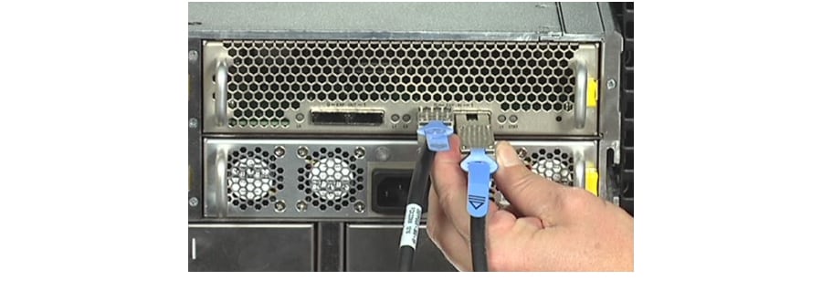
Step 2 ![]() Insert the other ends of the SAS cables into the EXP IN 0 and 1 SAS ports on one of the Expansion Controllers in the CPS-SS-4RU-EX.
Insert the other ends of the SAS cables into the EXP IN 0 and 1 SAS ports on one of the Expansion Controllers in the CPS-SS-4RU-EX.
Figure 4-1 Plugging the SAS cables into the Expansion Controller
Step 3 ![]() Repeat Step 1 and Step 2 for the second RAID Controller and Expansion Module.
Repeat Step 1 and Step 2 for the second RAID Controller and Expansion Module.
NOTE: If the main storage unit is a single-controller unit, Step 3 will not apply.
Either RAID Controller can be connected to either Expansion Controller. However, you cannot connect one RAID Controller to more than one Expansion Controller, or more than one RAID Controller to an Expansion Controller.

Note ![]() The maximum SAS cable length is 4m. Applications requiring greater than 4m should consult Technical Support.
The maximum SAS cable length is 4m. Applications requiring greater than 4m should consult Technical Support.
Powering Up the Units
CPS-SS-4RU-EX

Step 1 ![]() Using the two supplied power cords, connect each PSU on the CPS-SS-4RU-EX to main power.
Using the two supplied power cords, connect each PSU on the CPS-SS-4RU-EX to main power.
Step 2 ![]() Wait approximately 10 seconds, then power up the unit to which the CPS-SS-4RU-EX is attached (see CPS-SS-4RU, CPS-SS-4RU).
Wait approximately 10 seconds, then power up the unit to which the CPS-SS-4RU-EX is attached (see CPS-SS-4RU, CPS-SS-4RU).
Step 3 ![]() Once the main unit is fully powered up, check the EXP IN L0 and L1 LEDs next to the SAS ports on the Expansion Modules. Both LEDs should be green.
Once the main unit is fully powered up, check the EXP IN L0 and L1 LEDs next to the SAS ports on the Expansion Modules. Both LEDs should be green.
Note ![]() If either of the EXP IN LEDs are flashing amber, you must power down both units, correct the cabling (see Attaching Communication and Expansion Cables, CPS-SS-4RU-EX), and then repeat steps 1 through 3.
If either of the EXP IN LEDs are flashing amber, you must power down both units, correct the cabling (see Attaching Communication and Expansion Cables, CPS-SS-4RU-EX), and then repeat steps 1 through 3.
After the unit has finished booting up, you can configure it using the graphical user interface (GUI). For detailed instructions, see the Software Manual.
CPS-SS-4RU
Note ![]() If you are connecting a CPS-SS-4RU-EX to your CPS-SS-4RU, power up the CPS-SS-4RU-EX first (see CPS-SS-4RU-EX).
If you are connecting a CPS-SS-4RU-EX to your CPS-SS-4RU, power up the CPS-SS-4RU-EX first (see CPS-SS-4RU-EX).
Step 1 ![]() Using the two supplied power cords, connect each PSU to main power.
Using the two supplied power cords, connect each PSU to main power.
Step 2 ![]() If necessary, press and hold one of the two SW0 switches on the rear of the unit for 4 seconds to initiate the power-up sequence.
If necessary, press and hold one of the two SW0 switches on the rear of the unit for 4 seconds to initiate the power-up sequence.
Once the unit has finished booting up, you can configure it using the graphical user interface (GUI). For detailed instructions, see the Software Manual.
 Feedback