- Preface
- Introducing the Sensor
- Installing IDS-4215
- Installing IDS-4235 and IDS-4250
- Installing IPS-4240 and IPS-4255
- Installing IPS-4260
- Installing IPS 4270-20
- Installing AIM-IPS
- Installing AIP-SSM
- Installing IDSM-2
- Installing NM-CIDS
- Initializing the Sensor
- Logging In to the Sensor
- Obtaining Software
- Upgrading, Downgrading, and Installing System Images
- Troubleshooting
- Glossary
- Index
Cisco Intrusion Prevention System Appliance and Module Installation Guide for IPS 6.0
Bias-Free Language
The documentation set for this product strives to use bias-free language. For the purposes of this documentation set, bias-free is defined as language that does not imply discrimination based on age, disability, gender, racial identity, ethnic identity, sexual orientation, socioeconomic status, and intersectionality. Exceptions may be present in the documentation due to language that is hardcoded in the user interfaces of the product software, language used based on RFP documentation, or language that is used by a referenced third-party product. Learn more about how Cisco is using Inclusive Language.
- Updated:
- September 20, 2007
Chapter: Installing IDSM-2
Installing IDSM2

Note ![]() The number of concurrent CLI sessions is limited based on the platform. IDS 4215 and NM-CIDS are limited to three concurrent CLI sessions. All other platforms allow ten concurrent sessions.
The number of concurrent CLI sessions is limited based on the platform. IDS 4215 and NM-CIDS are limited to three concurrent CLI sessions. All other platforms allow ten concurrent sessions.
This chapter lists the software and hardware requirements of IDSM2, and describes how to remove and install it. It contains the following sections:
•![]() Software and Hardware Requirements
Software and Hardware Requirements
•![]() Minimum Supported IDSM2 Configurations
Minimum Supported IDSM2 Configurations
•![]() Using the TCP Reset Interface
Using the TCP Reset Interface
•![]() Installation and Removal Instructions
Installation and Removal Instructions
Specifications
Table 9-1 lists the specifications for IDSM2.
Software and Hardware Requirements
The following are the IDSM2 software and hardware requirements:
•![]() Catalyst software release 7.5(1) or later with Supervisor Engine 1A with MSFC2
Catalyst software release 7.5(1) or later with Supervisor Engine 1A with MSFC2
•![]() Catalyst software release 7.5(1) or later with Supervisor Engine 2 with MSFC2 or PFC2
Catalyst software release 7.5(1) or later with Supervisor Engine 2 with MSFC2 or PFC2
•![]() Cisco IOS software release 12.2(14)SY with Supervisor Engine 2 with MSFC2
Cisco IOS software release 12.2(14)SY with Supervisor Engine 2 with MSFC2
•![]() Cisco IOS software release 12.1(19)E or later with Supervisor Engine 2 with MSFC2
Cisco IOS software release 12.1(19)E or later with Supervisor Engine 2 with MSFC2
•![]() Cisco IOS software release 12.1(19)E1 or later with Supervisor Engine 1A with MSFC2
Cisco IOS software release 12.1(19)E1 or later with Supervisor Engine 1A with MSFC2
•![]() Cisco IOS software release 12.2(14)SX1 with Supervisor Engine 720
Cisco IOS software release 12.2(14)SX1 with Supervisor Engine 720
•![]() Cisco IDS software release 4.0 or later
Cisco IDS software release 4.0 or later
•![]() Any Catalyst 6500 series switch chassis or 7600 router
Any Catalyst 6500 series switch chassis or 7600 router
Minimum Supported IDSM2 Configurations
Note ![]() The following matrix is not intended to recommend any particular version, but rather lists the earliest supported versions.
The following matrix is not intended to recommend any particular version, but rather lists the earliest supported versions.
Table 9-2 lists the minimum supported configurations for IDSM2.
|
|
|
|
||||||
|---|---|---|---|---|---|---|---|---|
|
|
|
|
|
|
|
|
|
|
SPAN |
7.5(1) |
7.5(1) |
8.4(1) |
8.1(1) |
12.1(19)E1 |
12.1(19)E1 |
12.2(18)SXF1 |
12.2(14)SX1 |
VACL capture1 |
7.5(1) |
7.5(1) |
8.4(1) |
8.1(1) |
12.1(19)E1 |
12.1(19)E1 |
12.2(18)SXF1 |
12.2(14)SX1 |
ECLB with VACL capture2 |
8.5(1) |
8.5(1) |
8.5(1) |
8.5(1) |
N/A |
12.2(18)SXF4 |
12.2(18)SXF1 |
12.2(18)SXE1 |
Inline interface pairs |
8.4(1) |
8.4(1) |
8.4(1) |
8.4(1) |
N/A |
12.2(18)SXF4 |
12.2(18)SXF4 |
12.2(18)SXE1 |
ECLB with inline interface pairs |
8.5(1) |
8.5(1) |
8.5(1) |
8.5(1) |
N/A |
12.2(18)SXF4 |
12.2(18)SXF4 |
12.2(18)SXF4 |
Inline VLAN pairs |
8.4(1) |
8.4(1) |
8.4(1) |
8.4(1) |
N/A |
12.2(18)SXF4 |
12.2(18)SXF4 |
12.2(18)SXF4 |
ECLB with inline VLAN pairs |
8.5(1) |
8.5(1) |
8.5(1) |
8.5(1) |
N/A |
12.2(18)SXF4 |
12.2(18)SXF4 |
12.2(18)SXF4 |
1 Requires PFC2/3 or MSFC2/3. 2 Requires PFC2/3 or MSFC2/3. |
Using the TCP Reset Interface
The IDSM2 has a TCP reset interface—port 1. The IDSM2 has a specific TCP reset interface because it cannot send TCP resets on its sensing ports.
If you have reset problems with the IDSM2, and the switch is running Catalyst software, try the following:
•![]() If the sensing ports are access ports (a single VLAN), you need to configure the reset port to be in the same VLAN.
If the sensing ports are access ports (a single VLAN), you need to configure the reset port to be in the same VLAN.
•![]() If the sensing ports are dot1q trunk ports (multi-VLAN), the sensing ports and reset port all must have the same native VLAN, and the reset port must trunk all the VLANs being trunked by both the sensing ports.
If the sensing ports are dot1q trunk ports (multi-VLAN), the sensing ports and reset port all must have the same native VLAN, and the reset port must trunk all the VLANs being trunked by both the sensing ports.
Note ![]() In Cisco IOS when the IDSM2 is in promiscuous mode, the IDSM2 ports are always dot1q trunk ports (even when monitoring only 1 VLAN), and the TCP reset port is automatically set to a trunk port and is not configurable.
In Cisco IOS when the IDSM2 is in promiscuous mode, the IDSM2 ports are always dot1q trunk ports (even when monitoring only 1 VLAN), and the TCP reset port is automatically set to a trunk port and is not configurable.
Front Panel Features
IDSM2 has a status indicator and a Shutdown button.
Figure 9-1 shows the front panel features.
Figure 9-1 IDSM2 Front Panel
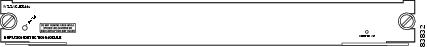
Table 9-3 describes the IDSM2 states as indicated by the status indicator.
To prevent corruption of IDSM2, you must use the shutdown command to shut it down properly. For instructions on properly shutting down IDSM2, see Step 1 of Removing IDSM2. If IDSM2 does not respond, firmly press the Shutdown button on the faceplate and wait for the Status indicator to turn amber. The shutdown procedure may take several minutes.

Installation and Removal Instructions
All Catalyst 6500 series switches support hot swapping, which lets you install, remove, replace, and rearrange modules without turning off the system power to the switch. When the system detects that a module has been installed or removed, it runs diagnostic and discovery routines, acknowledges the presence or absence of the module, and resumes system operation with no operator intervention.
This section contains the following topics:
Required Tools
Note ![]() You must have at least one supervisor engine running in the Catalyst 6500 series switch with IDSM2.
You must have at least one supervisor engine running in the Catalyst 6500 series switch with IDSM2.
You need the following tools to install IDSM2 in the Catalyst 6500 series switches:
•![]() Flat-blade screwdriver
Flat-blade screwdriver
•![]() Wrist strap or other grounding device
Wrist strap or other grounding device
•![]() Antistatic mat or antistatic foam
Antistatic mat or antistatic foam
Whenever you handle IDSM2, always use a wrist strap or other grounding device to prevent serious damage from ESD.
 |
Warning |
For More Information
•![]() For more information on supervisor engines, refer to the Catalyst 6500 Series Switch Installation Guide.
For more information on supervisor engines, refer to the Catalyst 6500 Series Switch Installation Guide.
•![]() For more information on working in ESD-controlled environments, see Site and Safety Guidelines.
For more information on working in ESD-controlled environments, see Site and Safety Guidelines.
Slot Assignments
Note ![]() The Catalyst 6509-NEB switch has vertical slots numbered 1 to 9 from right to left. Install IDSM2 with the component side facing to the right.
The Catalyst 6509-NEB switch has vertical slots numbered 1 to 9 from right to left. Install IDSM2 with the component side facing to the right.
The Catalyst 6006 and 6506 switch chassis each have six slots. The Catalyst 6009 and 6509 switch chassis each have nine slots. The Catalyst 6513 switch chassis has 13 slots. You can install IDSM2 in the following ways:
•![]() You can install IDSM2 in any slot that is not used by the supervisor engine.
You can install IDSM2 in any slot that is not used by the supervisor engine.
•![]() You can install up to eight IDSM2s in a single chassis.
You can install up to eight IDSM2s in a single chassis.
Note ![]() IDSM2 works with any supervisor engine using SPAN, but the copy capture feature with security VACLs requires that the supervisor engine has the PFC or the MSFC option.
IDSM2 works with any supervisor engine using SPAN, but the copy capture feature with security VACLs requires that the supervisor engine has the PFC or the MSFC option.
Installing IDSM2
To install IDSM2 in the Catalyst 6500 series switch, follow these steps:
Step 1 ![]() Make sure that you take necessary ESD precautions.
Make sure that you take necessary ESD precautions.
|
Warning |
Step 2 ![]() Choose a slot for IDSM2.
Choose a slot for IDSM2.
Note ![]() You can install IDSM2 in any slot that is not reserved for a supervisor engine or other module. Refer to your switch documentation for information about which slots are reserved for the supervisor engine or other modules.
You can install IDSM2 in any slot that is not reserved for a supervisor engine or other module. Refer to your switch documentation for information about which slots are reserved for the supervisor engine or other modules.
Step 3 ![]() Remove the installation screws (use a screwdriver, if necessary) that secure the filler plate to the desired slot.
Remove the installation screws (use a screwdriver, if necessary) that secure the filler plate to the desired slot.
Step 4 ![]() Remove the filler plate by prying it out carefully.
Remove the filler plate by prying it out carefully.
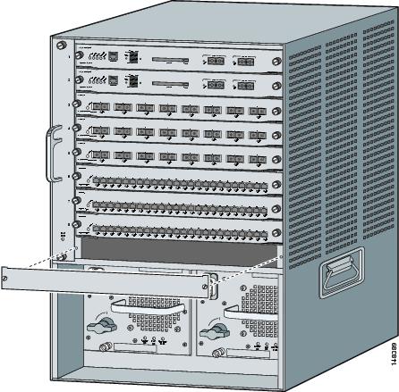
Step 5 ![]() Hold the IDSM2 with one hand, and place your other hand under the IDSM2 carrier to support it.
Hold the IDSM2 with one hand, and place your other hand under the IDSM2 carrier to support it.
Step 6 ![]() Place IDSM2 in the slot by aligning the notch on the sides of the IDSM2 carrier with the groove in the slot.
Place IDSM2 in the slot by aligning the notch on the sides of the IDSM2 carrier with the groove in the slot.
Step 7 ![]() Keeping IDSM2 at a 90-degree orientation to the backplane, carefully push it in to the slot until the notches on both ejector levers engage the chassis sides.
Keeping IDSM2 at a 90-degree orientation to the backplane, carefully push it in to the slot until the notches on both ejector levers engage the chassis sides.
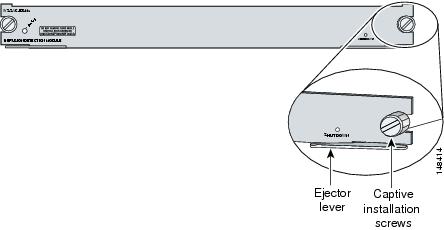
Step 8 ![]() Using the thumb and forefinger of each hand, simultaneously pivot in both ejector levers to fully seat IDSM2 in the backplane connector.
Using the thumb and forefinger of each hand, simultaneously pivot in both ejector levers to fully seat IDSM2 in the backplane connector.
Note ![]() If you perform a hot swap, the console displays the message
If you perform a hot swap, the console displays the message Module x has been inserted. This message does not appear, however, if you are connected to the Catalyst 6500 series switch through a Telnet session.
Step 9 ![]() Use a screwdriver to tighten the installation screws on the left and right ends of IDSM2.
Use a screwdriver to tighten the installation screws on the left and right ends of IDSM2.
Step 10 ![]() Verify that you have correctly installed IDSM2 and can bring it online.
Verify that you have correctly installed IDSM2 and can bring it online.
Step 11 ![]() Initialize IDSM2.
Initialize IDSM2.
Step 12 ![]() Configure the switch for command and control access to IDSM2.
Configure the switch for command and control access to IDSM2.
Step 13 ![]() Upgrade IDSM2 to the most recent Cisco IDS software.
Upgrade IDSM2 to the most recent Cisco IDS software.
Step 14 ![]() Set up IDSM2 to capture IPS traffic.
Set up IDSM2 to capture IPS traffic.
You are now ready to configure IDSM2 for intrusion prevention.
For More Information
•![]() For more information on ESD-controlled environments, see Site and Safety Guidelines.
For more information on ESD-controlled environments, see Site and Safety Guidelines.
•![]() For the procedure to make sure you installed IDSM2 properly, see Verifying Installation.
For the procedure to make sure you installed IDSM2 properly, see Verifying Installation.
•![]() For the procedure for using the setup command to initialize IDSM2, see Initializing IDSM2.
For the procedure for using the setup command to initialize IDSM2, see Initializing IDSM2.
•![]() For the procedure, refer to Configuring the Catalyst 6500 Series Switch for Command and Control Access to the IDSM2.
For the procedure, refer to Configuring the Catalyst 6500 Series Switch for Command and Control Access to the IDSM2.
•![]() For the procedure for obtaining the latest IPS software, see Obtaining Cisco IPS Software.
For the procedure for obtaining the latest IPS software, see Obtaining Cisco IPS Software.
•![]() For the procedure for configuring IDSM2 to capture IPS traffic, refer to Configuring IDSM2.
For the procedure for configuring IDSM2 to capture IPS traffic, refer to Configuring IDSM2.
Verifying Installation
Use the show module command to verify that the switch acknowledges IDSM2 and has brought it online.
To verify the installation, follow these steps:
Step 1 ![]() Log in to the console.
Log in to the console.
Step 2 ![]() For Catalyst software:
For Catalyst software:
console> (enable) show module
Mod Slot Ports Module-Type Model Sub Status
--- ---- ----- ------------------------- ------------------- --- --------
1 1 2 1000BaseX Supervisor WS-X6K-SUP1A-2GE yes ok
15 1 1 Multilayer Switch Feature WS-F6K-MSFC no ok
2 2 48 10/100BaseTX Ethernet WS-X6248-RJ-45 no ok
3 3 48 10/100/1000BaseT Ethernet WS-X6548-GE-TX no ok
4 4 16 1000BaseX Ethernet WS-X6516A-GBIC no ok
6 6 8 Intrusion Detection Mod WS-SVC-IDSM2 yes ok
Mod Module-Name Serial-Num
--- -------------------- -----------
1 SAD041308AN
15 SAD04120BRB
2 SAD03475400
3 SAD073906RC
4 SAL0751QYN0
6 SAD062004LV
Mod MAC-Address(es) Hw Fw Sw
--- -------------------------------------- ------ ---------- -----------------
1 00-d0-c0-cc-0e-d2 to 00-d0-c0-cc-0e-d3 3.1 5.3.1 8.4(1)
00-d0-c0-cc-0e-d0 to 00-d0-c0-cc-0e-d1
00-30-71-34-10-00 to 00-30-71-34-13-ff
15 00-30-7b-91-77-b0 to 00-30-7b-91-77-ef 1.4 12.1(23)E2 12.1(23)E2
2 00-30-96-2b-c7-2c to 00-30-96-2b-c7-5b 1.1 4.2(0.24)V 8.4(1)
3 00-0d-29-f6-01-98 to 00-0d-29-f6-01-c7 5.0 7.2(1) 8.4(1)
4 00-0e-83-af-15-48 to 00-0e-83-af-15-57 1.0 7.2(1) 8.4(1)
6 00-e0-b0-ff-3b-80 to 00-e0-b0-ff-3b-87 0.102 7.2(0.67) 5.0(0.30)
Mod Sub-Type Sub-Model Sub-Serial Sub-Hw Sub-Sw
--- ----------------------- ------------------- ----------- ------ ------
1 L3 Switching Engine WS-F6K-PFC SAD041303G6 1.1
6 IDS 2 accelerator board WS-SVC-IDSUPG . 2.0
console> (enable)
Step 3 ![]() For Cisco IOS software:
For Cisco IOS software:
router# show module
Mod Ports Card Type Model Serial No.
--- ----- -------------------------------------- ------------------ -----------
1 48 48 port 10/100 mb RJ-45 ethernet WS-X6248-RJ-45 SAD0401012S
2 48 48 port 10/100 mb RJ45 WS-X6348-RJ-45 SAL04483QBL
3 48 SFM-capable 48 port 10/100/1000mb RJ45 WS-X6548-GE-TX SAD073906GH
6 16 SFM-capable 16 port 1000mb GBIC WS-X6516A-GBIC SAL0740MMYJ
7 2 Supervisor Engine 720 (Active) WS-SUP720-3BXL SAD08320L2T
9 1 1 port 10-Gigabit Ethernet Module WS-X6502-10GE SAD071903BT
10 3 Anomaly Detector Module WS-SVC-ADM-1-K9 SAD084104JR
11 8 Intrusion Detection System WS-SVC-IDSM2 SAD05380608
13 8 Intrusion Detection System WS-SVC-IDSM2 SAD072405D8
Mod MAC addresses Hw Fw Sw Status
--- ---------------------------------- ------ ------------ ------------ -------
1 00d0.d328.e2ac to 00d0.d328.e2db 1.1 4.2(0.24)VAI 8.5(0.46)ROC Ok
2 0003.6c14.e1d0 to 0003.6c14.e1ff 1.4 5.4(2) 8.5(0.46)ROC Ok
3 000d.29f6.7a80 to 000d.29f6.7aaf 5.0 7.2(1) 8.5(0.46)ROC Ok
6 000d.ed23.1658 to 000d.ed23.1667 1.0 7.2(1) 8.5(0.46)ROC Ok
7 0011.21a1.1398 to 0011.21a1.139b 4.0 8.1(3) 12.2(PIKESPE Ok
9 000d.29c1.41bc to 000d.29c1.41bc 1.3 Unknown Unknown PwrDown
10 000b.fcf8.2ca8 to 000b.fcf8.2caf 0.101 7.2(1) 4.0(0.25) Ok
11 00e0.b0ff.3340 to 00e0.b0ff.3347 0.102 7.2(0.67) 5.0(1) Ok
13 0003.feab.c850 to 0003.feab.c857 4.0 7.2(1) 5.0(1) Ok
Mod Sub-Module Model Serial Hw Status
--- --------------------------- ------------------ ------------ ------- -------
7 Policy Feature Card 3 WS-F6K-PFC3BXL SAD083305A1 1.3 Ok
7 MSFC3 Daughterboard WS-SUP720 SAD083206JX 2.1 Ok
11 IDS 2 accelerator board WS-SVC-IDSUPG . 2.0 Ok
13 IDS 2 accelerator board WS-SVC-IDSUPG 0347331976 2.0 Ok
Mod Online Diag Status
--- -------------------
1 Pass
2 Pass
3 Pass
6 Pass
7 Pass
9 Unknown
10 Not Applicable
11 Pass
13 Pass
router#
Note ![]() It is normal for the status to read
It is normal for the status to read other when IDSM2 is first installed. After IDSM2 completes the diagnostics routines and comes online, the status reads ok. Allow up to 5 minutes for IDSM2 to come online.
For More Information
For information on enabling a full memory test after verifying IDSM2 installation, see Enabling Full Memory Tests.
Removing IDSM2
This procedure describes how to remove IDSM2 from the Catalyst 6500 series switch.
|
Warning |
|
Warning |
To remove IDSM2, follow these steps:
Step 1 ![]() Shut down IDSM2 by one of these methods:
Shut down IDSM2 by one of these methods:
•![]() Log in to the IDSM2 CLI and enter reset powerdown.
Log in to the IDSM2 CLI and enter reset powerdown.
Note ![]() The reset powerdown command performs a shut down but does not remove power from IDSM2. To remove power from IDSM2, use the set module power down module_number command.
The reset powerdown command performs a shut down but does not remove power from IDSM2. To remove power from IDSM2, use the set module power down module_number command.
•![]() Log in to the switch CLI and enter one of the following commands:
Log in to the switch CLI and enter one of the following commands:
–![]() For Catalyst software:
For Catalyst software:
set module shutdown module_number
–![]() For Cisco IOS software:
For Cisco IOS software:
hw-module module module_number shutdown
•![]() Shut down IDSM2 through IDM.
Shut down IDSM2 through IDM.
•![]() Press the Shutdown button.
Press the Shutdown button.
Note ![]() Shutdown may take several minutes.
Shutdown may take several minutes.
Step 2 ![]() Verify that IDSM2 shuts down. Do not remove IDSM2 until the status indicator is amber or off.
Verify that IDSM2 shuts down. Do not remove IDSM2 until the status indicator is amber or off.
Step 3 ![]() Use a screwdriver to loosen the installation screws at the left and right sides of IDSM2.
Use a screwdriver to loosen the installation screws at the left and right sides of IDSM2.
Step 4 ![]() Grasp the left and right ejector levers and simultaneously pull the left lever to the left and the right lever to the right to release IDSM2 from the backplane connector.
Grasp the left and right ejector levers and simultaneously pull the left lever to the left and the right lever to the right to release IDSM2 from the backplane connector.
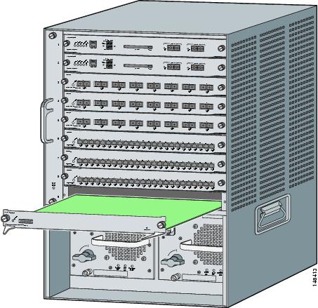
Step 5 ![]() As you pull IDSM2 out of the slot, place one hand under the carrier to support it.
As you pull IDSM2 out of the slot, place one hand under the carrier to support it.
Step 6 ![]() Carefully pull IDSM2 straight out of the slot, keeping your other hand under the carrier to guide it.
Carefully pull IDSM2 straight out of the slot, keeping your other hand under the carrier to guide it.
Note ![]() Keep IDSM2 at a 90-degree orientation to the backplane (horizontal to the floor).
Keep IDSM2 at a 90-degree orientation to the backplane (horizontal to the floor).
Step 7 ![]() Place IDSM2 on an antistatic mat or antistatic foam.
Place IDSM2 on an antistatic mat or antistatic foam.
Step 8 ![]() If the slot is to remain empty, install a filler plate (part number 800-00292-01) to keep dust out of the chassis and to maintain proper airflow through the module compartment.
If the slot is to remain empty, install a filler plate (part number 800-00292-01) to keep dust out of the chassis and to maintain proper airflow through the module compartment.
For More Information
•![]() For more information on ESD-controlled environments, see Site and Safety Guidelines.
For more information on ESD-controlled environments, see Site and Safety Guidelines.
•![]() For the procedure for restoring the application partition, see Installing the IDSM2 System Image.
For the procedure for restoring the application partition, see Installing the IDSM2 System Image.
•![]() For the procedure for resetting IDSM2, see Resetting IDSM2.
For the procedure for resetting IDSM2, see Resetting IDSM2.
•![]() For the procedure for powering IDSM2 up and down, see Powering IDSM2 Up and Down.
For the procedure for powering IDSM2 up and down, see Powering IDSM2 Up and Down.
Enabling Full Memory Tests
When IDSM2 initially boots, by default it runs a partial memory test. You can enable a full memory test in Catalyst software and Cisco IOS software.
This section describes how to enable memory tests, and contains the following topics:
Catalyst Software
Use the set boot device boot_sequence module_number mem-test-full command to enable a full memory test. The full memory test takes about 12 minutes.
To enable a full memory test, follow these steps:
Step 1 ![]() Log in to the console.
Log in to the console.
Step 2 ![]() Enter privileged mode:
Enter privileged mode:
console> enable
Step 3 ![]() Enable the full memory test:
Enable the full memory test:
console> (enable) set boot dev cf:1 3 mem-test-full
Device BOOT variable = cf:1
Memory-test set to FULL
Warning: Device list is not verified but still set in the boot string.
console> (enable) set boot dev hdd:1 3 mem-test-full
Device BOOT variable = hdd:1
Memory-test set to FULL
Warning: Device list is not verified but still set in the boot string.
console> (enable)
The set boot device command can either contain cf:1 or hdd:1.
Step 4 ![]() Reset IDSM2.
Reset IDSM2.
The full memory test runs.
Note ![]() A full memory test takes more time to complete than a partial memory test.
A full memory test takes more time to complete than a partial memory test.
For More Information
For the procedure for resetting IDSM2, see Resetting IDSM2.
Cisco IOS Software
Use the hw-module module module_number reset mem-test-full command to enable a full memory test. The full memory test takes about 12 minutes.
To enable a full memory test, follow these steps:
Step 1 ![]() Log in to the console.
Log in to the console.
Step 2 ![]() Enable the full memory test:
Enable the full memory test:
router# hw-module module 9 reset mem-test-full
Device BOOT variable for reset = <empty>
Warning: Device list is not verified.
Proceed with reload of module?[confirm]
% reset issued for module 9
router#
Step 3 ![]() Reset IDSM2.
Reset IDSM2.
The full memory test runs.
Note ![]() A full memory test takes more time to complete than a partial memory test.
A full memory test takes more time to complete than a partial memory test.
For More Information
For the procedure for resetting IDSM2, see Resetting IDSM2.
Resetting IDSM2
If for some reason you cannot communicate with IDSM2 through SSH, Telnet, or the switch session command, you must reset IDSM2 from the switch console. The reset process requires several minutes.
This section describes how to reset the IDSM2, and contains the following topics:
Catalyst Software
To reset IDSM2 from the CLI, follow these steps:
Step 1 ![]() Log in to the console.
Log in to the console.
Step 2 ![]() Enter privileged mode:
Enter privileged mode:
console> enable
Step 3 ![]() Reset IDSM2 to the application partition or the maintenance partition:
Reset IDSM2 to the application partition or the maintenance partition:
console> (enable) reset module_number [hdd:1 | cf:1]
Note ![]() If you do not specify either the application partition (hdd:1 the default) or the maintenance partition (cf:1), IDSM2 uses the boot device variable.
If you do not specify either the application partition (hdd:1 the default) or the maintenance partition (cf:1), IDSM2 uses the boot device variable.
Example:
console> (enable) reset 3
2003 Feb 01 00:18:23 %SYS-5-MOD_RESET: Module 3 reset from console//
Resetting module 3... This may take several minutes.
2003 Feb 01 00:20:03 %SYS-5-MOD_OK: Module 3 is online.
console> (enable)
For More Information
For the procedure for reimaging IDSM2, see Installing the IDSM2 System Image.
Cisco IOS Software
Use the hw-module module slot_number reset [hdd:1 | cf:1] command in EXEC mode to reset IDSM2. The reset process takes several minutes. IDSM2 boots in to the boot partition you specify. If you do not specify the boot string, the default boot string is used.
To reset IDSM2 from the CLI, follow these steps:
Step 1 ![]() Log in to the console.
Log in to the console.
Step 2 ![]() Reset IDSM2:
Reset IDSM2:
router# hw-module module module-number reset [hdd:1 | cf:1]
Note ![]() If you do not specify either the application partition (hdd:1 the default) or the maintenance partition (cf:1), IDSM2 uses the boot device variable.
If you do not specify either the application partition (hdd:1 the default) or the maintenance partition (cf:1), IDSM2 uses the boot device variable.
Example:
router# hw-module module 8 reset
Device BOOT variable for reset =
Warning: Device list is not verified.
Proceed with reload of module? [confirm]
% reset issued for module 8
router#
Powering IDSM2 Up and Down
You can remove and restore power to IDSM2 through the switch CLI. This section describes how to power IDSM2 up and down through the switch CLI, and contains the following sections:
Catalyst Software
Once you power off IDSM2, you must power it up through the switch CLI.
Note ![]() The IDSM2 CLI reset powerdown command performs a shut down, but does not remove power from IDSM2.
The IDSM2 CLI reset powerdown command performs a shut down, but does not remove power from IDSM2.
To power IDSM2 up and down from the switch CLI, follow these steps:
Step 1 ![]() Log in to the console.
Log in to the console.
Step 2 ![]() Enter privileged mode:
Enter privileged mode:
console> enable
Step 3 ![]() Power up IDSM2:
Power up IDSM2:
console> (enable) set module power up module_number
Step 4 ![]() Power down IDSM2:
Power down IDSM2:
console> (enable) set module power down module_number
Cisco IOS Software
Once you power off IDSM2, you must power it up through the switch CLI.
Note ![]() The IDSM2 CLI reset powerdown command performs a shut down, but does not remove power from IDSM2.
The IDSM2 CLI reset powerdown command performs a shut down, but does not remove power from IDSM2.
To power IDSM2 up and down from the switch CLI, follow these steps:
Step 1 ![]() Log in to the console.
Log in to the console.
Step 2 ![]() Enter configure terminal mode:
Enter configure terminal mode:
router# configure terminal
Step 3 ![]() Power up IDSM2:
Power up IDSM2:
router(config)# power enable module module_number
Step 4 ![]() Power down IDSM2:
Power down IDSM2:
router(config)# no power enable module module_number
 Feedback