- Preface
- Introducing the Sensor
- Installing IDS-4215
- Installing IDS-4235 and IDS-4250
- Installing IPS-4240 and IPS-4255
- Installing IPS-4260
- Installing IPS 4270-20
- Installing AIM-IPS
- Installing AIP-SSM
- Installing IDSM-2
- Installing NM-CIDS
- Initializing the Sensor
- Logging In to the Sensor
- Obtaining Software
- Upgrading, Downgrading, and Installing System Images
- Troubleshooting
- Glossary
- Index
Cisco Intrusion Prevention System Appliance and Module Installation Guide for IPS 6.0
Bias-Free Language
The documentation set for this product strives to use bias-free language. For the purposes of this documentation set, bias-free is defined as language that does not imply discrimination based on age, disability, gender, racial identity, ethnic identity, sexual orientation, socioeconomic status, and intersectionality. Exceptions may be present in the documentation due to language that is hardcoded in the user interfaces of the product software, language used based on RFP documentation, or language that is used by a referenced third-party product. Learn more about how Cisco is using Inclusive Language.
- Updated:
- September 20, 2007
Chapter: Installing IPS-4240 and IPS-4255
Installing IPS 4240 and IPS 4255

Note ![]() The number of concurrent CLI sessions is limited based on the platform. IDS 4215 and NM-CIDS are limited to three concurrent CLI sessions. All other platforms allow ten concurrent sessions.
The number of concurrent CLI sessions is limited based on the platform. IDS 4215 and NM-CIDS are limited to three concurrent CLI sessions. All other platforms allow ten concurrent sessions.
This chapter describes IPS 4240 and IPS 4255 and how to install them. It also describes the accessories and how to install them. It contains the following sections:
•![]() Introducing IPS 4240 and IPS 4255
Introducing IPS 4240 and IPS 4255
•![]() Front and Back Panel Features
Front and Back Panel Features
•![]() Connecting IPS 4240 to a Cisco 7200 Series Router
Connecting IPS 4240 to a Cisco 7200 Series Router
•![]() Installing IPS 4240 and IPS 4255
Installing IPS 4240 and IPS 4255
Introducing IPS 4240 and IPS 4255
Note ![]() IPS 4240 and the IPS 4255 do not support redundant power supplies.
IPS 4240 and the IPS 4255 do not support redundant power supplies.
IPS 4240 and IPS 4255 deliver high port density in a small form factor. They use a compact flash device for storage rather than the hard-disk drives used in other sensor models.
IPS 4240 monitors up to 250 Mbps of aggregate network traffic on multiple sensing interfaces and is inline ready. It replaces IDS 4235. There are four 10/100/1000 copper sensing interfaces. IPS 4240 is available with either AC or DC power.
Note ![]() The 250-Mbps performance for IPS 4240 is based on the following conditions: 2500 new TCP connections per second, 2500 HTTP transactions per second, average packet size of 445 bytes, and the system running Cisco IPS 5.1 software. The 250-Mbps performance is traffic combined from all four sensing interfaces.
The 250-Mbps performance for IPS 4240 is based on the following conditions: 2500 new TCP connections per second, 2500 HTTP transactions per second, average packet size of 445 bytes, and the system running Cisco IPS 5.1 software. The 250-Mbps performance is traffic combined from all four sensing interfaces.
IPS 4255 monitors up to 600 Mbps of aggregate network traffic on multiple sensing interfaces and is also inline ready. It replaces IDS 4250-TX. There are four 10/100/1000 copper sensing interfaces. IDS 4250-SX and the IDS 4250-XL are not being replaced by IPS 4255 at this time.
Note ![]() The 600-Mbps performance for IPS 4255 is based on the following conditions: 6000 new TCP connections per second, 6000 HTTP transactions per second, average packet size of 445 bytes, and the system running Cisco IPS 5.1 software. The 600-Mbps performance is traffic combined from all four sensing interfaces.
The 600-Mbps performance for IPS 4255 is based on the following conditions: 6000 new TCP connections per second, 6000 HTTP transactions per second, average packet size of 445 bytes, and the system running Cisco IPS 5.1 software. The 600-Mbps performance is traffic combined from all four sensing interfaces.
Front and Back Panel Features
This section describes the IPS 4240 and IPS 4255 front and back panel features and indicators.
Note ![]() Although the graphics show IPS 4240, the IPS 4255 has the same front and back panel features and indicators.
Although the graphics show IPS 4240, the IPS 4255 has the same front and back panel features and indicators.
Figure 4-1 shows the front view of IPS 4240 and IPS 4255.
Figure 4-1 IPS 4240/IPS 4255 Front Panel Features
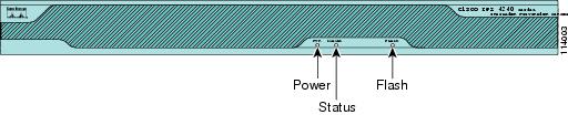
Table 4-1 describes the front panel indicators on IPS 4240 and IPS 4255.
Figure 4-2 shows the back view of the IPS 4240 and IPS 4255.
Figure 4-2 IPS 4240 and IPS 4255 Back Panel Features
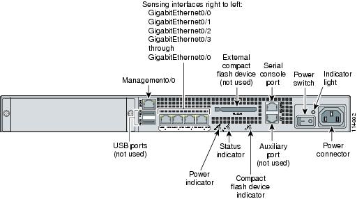
Figure 4-3 shows the four built-in Ethernet ports, which have two indicators per port.
Figure 4-3 Ethernet Port Indicators
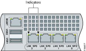
Table 4-2 lists the back panel indicators.
|
|
|
|
|---|---|---|
Left side |
Green solid |
Physical link |
Right side |
Not lit |
10 Mbps |
Specifications
Table 4-3 lists the specifications for IPS 4240 and IPS 4255.
Connecting IPS 4240 to a Cisco 7200 Series Router
When an IPS 4240 is connected directly to a 7200 series router and both the IPS 4240 and the router interfaces are hard-coded to speed 100 with duplex Full, the connection does not work. If you set IPS 4240 to speed Auto and duplex Auto, it connects to the router but only at speed 100 and duplex Half.
To connect correctly at speed 100 and duplex Full, set the interfaces of both IPS 4240 and the router to speed Auto and duplex Auto. Also, if either interface is hard-coded, you must make the connection using a crossover cable.
Accessories
 |
Warning |
IPS 4240 and IPS 4255 accessories kit contains the following:
•![]() DB25 connector
DB25 connector
•![]() DB9 connector
DB9 connector
•![]() Rack mounting kit—screws, washers, and metal bracket
Rack mounting kit—screws, washers, and metal bracket
•![]() RJ45 console cable
RJ45 console cable
•![]() Two 6-ft Ethernet cables
Two 6-ft Ethernet cables
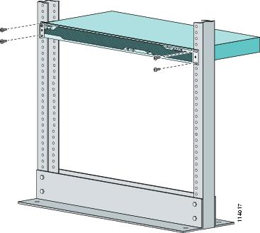
Rack Mounting
To rack mount IPS-424 and IPS 4255, follow these steps:
Step 1 ![]() Attach the bracket to the appliance using the supplied screws.
Attach the bracket to the appliance using the supplied screws.
You can attach the brackets to the holes near the front of the appliance.
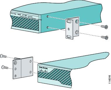
Note ![]() The top hole on the left bracket is a banana jack you can use for ESD grounding purposes when you are servicing the system. You can use the two threaded holes to mount a ground lug to ground the chassis.
The top hole on the left bracket is a banana jack you can use for ESD grounding purposes when you are servicing the system. You can use the two threaded holes to mount a ground lug to ground the chassis.
Step 2 ![]() Use the supplied screws to attach the appliance to the equipment rack.
Use the supplied screws to attach the appliance to the equipment rack.
Step 3 ![]() To remove the appliance from the rack, remove the screws that attach the appliance to the rack, and then remove the appliance.
To remove the appliance from the rack, remove the screws that attach the appliance to the rack, and then remove the appliance.
Installing IPS 4240 and IPS 4255
|
Warning |

To install IPS 4240 and IPS 4255 on the network, follow these steps:
Step 1 ![]() Position the appliance on the network.
Position the appliance on the network.
Step 2 ![]() Attach the grounding lug to the side of the appliance.
Attach the grounding lug to the side of the appliance.
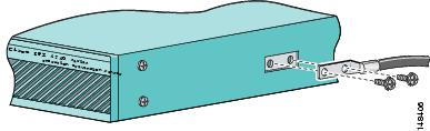
Note ![]() Use 8-32 screws to connect a copper standard barrel grounding lug to the holes. The appliance requires a lug where the distance between the center of each hole is 0.56 inches. The ground lug must be NRTL listed or recognized. In addition, the copper conductor (wires) must be used and the copper conductor must comply with the NEC code for ampacity. A lug is not supplied with the appliance.
Use 8-32 screws to connect a copper standard barrel grounding lug to the holes. The appliance requires a lug where the distance between the center of each hole is 0.56 inches. The ground lug must be NRTL listed or recognized. In addition, the copper conductor (wires) must be used and the copper conductor must comply with the NEC code for ampacity. A lug is not supplied with the appliance.
Step 3 ![]() Place the appliance in a rack, if you are rack mounting it.
Place the appliance in a rack, if you are rack mounting it.
Step 4 ![]() Attach the power cord to the appliance and plug it in to a power source (a UPS is recommended).
Attach the power cord to the appliance and plug it in to a power source (a UPS is recommended).
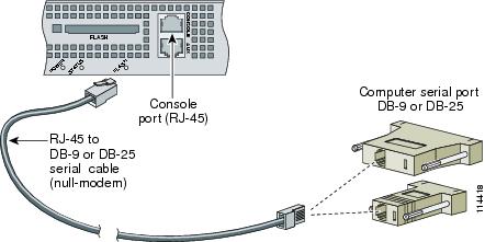
Step 5 ![]() Connect the cable as shown in Step 6 so that you have either a DB-9 or DB-25 connector on one end as required by the serial port for your computer, and the other end is the RJ-45 connector.
Connect the cable as shown in Step 6 so that you have either a DB-9 or DB-25 connector on one end as required by the serial port for your computer, and the other end is the RJ-45 connector.
Note ![]() Use the console port to connect to a computer to enter configuration commands. Locate the serial cable from the accessory kit. The serial cable assembly consists of a 180/rollover cable with RJ-45 connectors (DB-9 connector adapter PN 74-0495-01 and DB-25 connector adapter PN 29-0810-01).
Use the console port to connect to a computer to enter configuration commands. Locate the serial cable from the accessory kit. The serial cable assembly consists of a 180/rollover cable with RJ-45 connectors (DB-9 connector adapter PN 74-0495-01 and DB-25 connector adapter PN 29-0810-01).
Note ![]() You can use a 180/rollover or straight-through patch cable to connect the appliance to a port on a terminal server with RJ-45 or hydra cable assembly connections. Connect the appropriate cable from the console port on the appliance to a port on the terminal server.
You can use a 180/rollover or straight-through patch cable to connect the appliance to a port on a terminal server with RJ-45 or hydra cable assembly connections. Connect the appropriate cable from the console port on the appliance to a port on the terminal server.
Step 6 ![]() Connect the RJ-45 connector to the console port and connect the other end to the DB-9 or DB-25 connector on your computer.
Connect the RJ-45 connector to the console port and connect the other end to the DB-9 or DB-25 connector on your computer.
Step 7 ![]() Attach the network cables.
Attach the network cables.
•![]() GigabitEthernet0/0, GigabitEthernet0/1, GigabitEthernet0/2, and GigabitEthernet0/3 (from right to left) are sensing ports.
GigabitEthernet0/0, GigabitEthernet0/1, GigabitEthernet0/2, and GigabitEthernet0/3 (from right to left) are sensing ports.
•![]() Management0/0 is the command and control port.
Management0/0 is the command and control port.
Step 8 ![]() Power on the appliance.
Power on the appliance.
Step 9 ![]() Initialize the appliance.
Initialize the appliance.
Step 10 ![]() Upgrade the appliance with the most recent Cisco IPS software.
Upgrade the appliance with the most recent Cisco IPS software.
You are now ready to configure intrusion prevention on the appliance.
For More Information
•![]() For more information on working with electrical power and in an ESD environment, see Site and Safety Guidelines.
For more information on working with electrical power and in an ESD environment, see Site and Safety Guidelines.
•![]() For the procedure for mounting the appliance in a rack, see Rack Mounting.
For the procedure for mounting the appliance in a rack, see Rack Mounting.
•![]() For the instructions for setting up a terminal server, see Connecting an Appliance to a Terminal Server.
For the instructions for setting up a terminal server, see Connecting an Appliance to a Terminal Server.
•![]() For the procedure for using the setup command to initialize the appliance, see Initializing the Appliance.
For the procedure for using the setup command to initialize the appliance, see Initializing the Appliance.
•![]() For the procedure for obtaining the latest IPS software, see Obtaining Cisco IPS Software.
For the procedure for obtaining the latest IPS software, see Obtaining Cisco IPS Software.
•![]() If you have the IPS 4240 DC model, see Installing IPS 4240-DC.
If you have the IPS 4240 DC model, see Installing IPS 4240-DC.
•![]() For the procedure for using HTTPS to log in to IDM, refer to Logging In to IDM.
For the procedure for using HTTPS to log in to IDM, refer to Logging In to IDM.
•![]() For the procedures for configuring intrusion prevention on your sensor, refer to the following documents:
For the procedures for configuring intrusion prevention on your sensor, refer to the following documents:
–![]() Installing and Using Cisco Intrusion Prevention System Device Manager 6.0
Installing and Using Cisco Intrusion Prevention System Device Manager 6.0
–![]() Configuring the Cisco Intrusion Prevention System Sensor Using the Command Line Interface 6.0
Configuring the Cisco Intrusion Prevention System Sensor Using the Command Line Interface 6.0
Installing IPS 4240-DC
The IPS 4240-DC-K9 (NEBS-compliant) model equipped with DC-input power supply must be terminated with the DC input wiring on a DC source capable of supplying at least 15 amps. A 15-amp circuit breaker is required at the 48 VDC facility power source. An easily accessible disconnect device should be incorporated in to the facility wiring.
DC power guidelines are listed in Regulatory Compliance and Safety Information for the Cisco Intrusion Prevention System 4200 Series Appliance Sensor. For more information on working with electrical power and in an ESD environment, see Site and Safety Guidelines.
Note ![]() The DC return connection should remain isolated from the system frame and chassis (DC-I). This equipment is suitable for connection to intra-building wiring only.
The DC return connection should remain isolated from the system frame and chassis (DC-I). This equipment is suitable for connection to intra-building wiring only.
|
Warning |
To install IPS 4240-DC, follow these steps:
Step 1 ![]() Position IPS 4240-DC on the network.
Position IPS 4240-DC on the network.
Step 2 ![]() Attach the grounding lug to the side of the appliance.
Attach the grounding lug to the side of the appliance.
Note ![]() Use 8-32 screws to connect a copper standard barrel grounding lug to the holes. The appliance requires a lug where the distance between the center of each hole is 0.56 inches. The ground lug must be NRTL listed or recognized. In addition, the copper conductor (wires) must be used and the copper conductor must comply with the NEC code for ampacity. A lug is not supplied with the appliance.
Use 8-32 screws to connect a copper standard barrel grounding lug to the holes. The appliance requires a lug where the distance between the center of each hole is 0.56 inches. The ground lug must be NRTL listed or recognized. In addition, the copper conductor (wires) must be used and the copper conductor must comply with the NEC code for ampacity. A lug is not supplied with the appliance.
Step 3 ![]() Place the appliance in a rack, if you are rack mounting it.
Place the appliance in a rack, if you are rack mounting it.
Step 4 ![]() Terminate the DC input wiring on a DC source capable of supplying at least 15 amps.
Terminate the DC input wiring on a DC source capable of supplying at least 15 amps.
A 15-amp circuit breaker is required at the 48-VDC facility power source. An easily accessible disconnect device should be incorporated in to the facility wiring.
Step 5 ![]() Locate the DC-input terminal box.
Locate the DC-input terminal box.
Step 6 ![]() Power off IPS 4240-DC.
Power off IPS 4240-DC.
Make sure that power is removed from the DC circuit. To make sure all power is OFF, locate the circuit breaker on the panel board that services the DC circuit, switch the circuit breaker to the OFF position, and tape the switch handle of the circuit breaker in the OFF position.
Step 7 ![]() Remove the DC power supply plastic shield.
Remove the DC power supply plastic shield.
Step 8 ![]() Strip the ends of the wires for insertion in to the power connect lugs on IPS 4240-DC.
Strip the ends of the wires for insertion in to the power connect lugs on IPS 4240-DC.
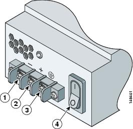
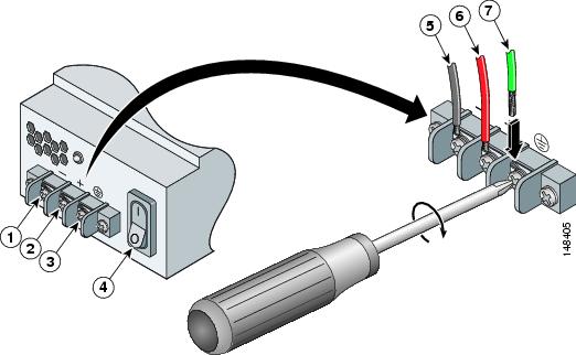
Step 9 ![]() Insert the ground wire in to the connector for the earth ground and tighten the screw on the connector. Using the same method as for the ground wire, connect the negative wire and then the positive wire.
Insert the ground wire in to the connector for the earth ground and tighten the screw on the connector. Using the same method as for the ground wire, connect the negative wire and then the positive wire.
|
|
Negative |
|
Negative |
|
|
Positive |
|
Positive |
|
|
Ground |
|
Ground |
|
|
On/Off Switch |
Note ![]() The DC return connection to this system is to remain isolated from the system frame and chassis.
The DC return connection to this system is to remain isolated from the system frame and chassis.
Step 10 ![]() After wiring the DC power supply, remove the tape from the circuit breaker switch handle and reinstate power by moving the handle of the circuit breaker to the ON position.
After wiring the DC power supply, remove the tape from the circuit breaker switch handle and reinstate power by moving the handle of the circuit breaker to the ON position.
Step 11 ![]() Replace the DC power supply plastic shield.
Replace the DC power supply plastic shield.
Step 12 ![]() Power on IPS 4240-DC from the switch at the back of the chassis.
Power on IPS 4240-DC from the switch at the back of the chassis.
Note ![]() If you need to power cycle IPS 4240-DC, wait at least 5 seconds between powering it off and powering it back on.
If you need to power cycle IPS 4240-DC, wait at least 5 seconds between powering it off and powering it back on.
Step 13 ![]() Initialize IPS 4240-DC.
Initialize IPS 4240-DC.
Step 14 ![]() Upgrade IPS 4240-DC with the most recent Cisco IPS software.
Upgrade IPS 4240-DC with the most recent Cisco IPS software.
You are now ready to configure intrusion prevention on the appliance.
For More Information
•![]() For the procedure for mounting the appliance in a rack, see Rack Mounting.
For the procedure for mounting the appliance in a rack, see Rack Mounting.
•![]() For the procedure for using the setup command to initialize the appliance, see Initializing the Appliance.
For the procedure for using the setup command to initialize the appliance, see Initializing the Appliance.
•![]() For the procedure for obtaining the latest IPS software, see Obtaining Cisco IPS Software.
For the procedure for obtaining the latest IPS software, see Obtaining Cisco IPS Software.
•![]() For the procedure for using HTTPS to log in to IDM, refer to Logging In to IDM.
For the procedure for using HTTPS to log in to IDM, refer to Logging In to IDM.
•![]() For the procedures for configuring intrusion prevention on your sensor, refer to the following documents:
For the procedures for configuring intrusion prevention on your sensor, refer to the following documents:
–![]() Installing and Using Cisco Intrusion Prevention System Device Manager 6.0
Installing and Using Cisco Intrusion Prevention System Device Manager 6.0
–![]() Configuring the Cisco Intrusion Prevention System Sensor Using the Command Line Interface 6.0
Configuring the Cisco Intrusion Prevention System Sensor Using the Command Line Interface 6.0
 Feedback