- Introduction to the Firepower System
- Deploying on a Management Network
- Deploying Firepower Managed Devices
- Preparing for the Installation
- Installing a Firepower Managed Device
- Setting Up Firepower Managed Devices
- Using the LCD Panel on a Firepower Device
- Hardware Specifications
- Restoring a Firepower System Appliance to Factory Defaults
- Power Requirements for Firepower Devices
- Using SFP Transceivers in Firepower 71x5 and AMP7150 Devices
- Inserting and Removing Firepower 8000 Series Modules
- Scrubbing the Hard Drive
- Preconfiguring Firepower Managed Devices
Cisco Firepower 7000 and 8000 Series Installation Guide, Version 6.x
Bias-Free Language
The documentation set for this product strives to use bias-free language. For the purposes of this documentation set, bias-free is defined as language that does not imply discrimination based on age, disability, gender, racial identity, ethnic identity, sexual orientation, socioeconomic status, and intersectionality. Exceptions may be present in the documentation due to language that is hardcoded in the user interfaces of the product software, language used based on RFP documentation, or language that is used by a referenced third-party product. Learn more about how Cisco is using Inclusive Language.
- Updated:
- November 10, 2015
Chapter: Inserting and Removing Firepower 8000 Series Modules
Inserting and Removing Firepower 8000 Series Modules
Firepower 8000 Series devices allow for modular flexibility in your deployment. Use the steps in this section to:
Module Slots on the Firepower 8000 Series Devices
Firepower 8000 Series devices can use the modules in the following slots:
After you insert the modules into your device, see the following sections for more information on using the modules:
- For information on configuring the sensing interfaces, see Identifying the Sensing Interfaces.
- For information on using the stacking module, see Using Devices in a Stacked Configuration.
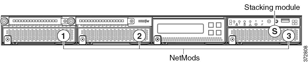
Firepower 81xx Family
Firepower 81xx Family devices can use the modules in the following slots:
Figure C-1 Firepower 81xx Family Primary Device
Stacking Configuration Considerations
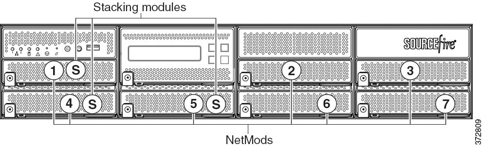
Firepower 82xx Family and 83xx Family
Firepower 82xx Family and 83xx Family devices can use the modules in the following slots:
Figure C-2 Firepower 82xx Family and 83xx Family Primary Device
Stacking Configuration Considerations
Configure the modules as follows for stacked devices:
- Install NetMods on the primary device only.
- Install one stacking module on the primary device for each stacked secondary device, and one stacking module on each secondary device.
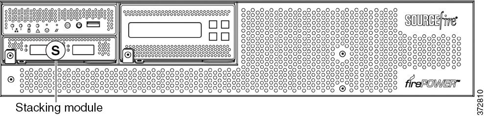
Figure C-3 Firepower 82xx Family and 83xx Family Secondary Device
Included Items
Your module assembly kit includes a T8 Torx screwdriver and one or more of the following modules:
- quad-port 1000BASE-T copper configurable bypass NetMod. For more information, see Quad-Port 1000BASE-T Copper Configurable Bypass NetMod.
- quad-port 1000BASE-SX fiber configurable bypass NetMod. For more information, see Quad-Port 1000BASE-SX Fiber Configurable Bypass NetMod.
- dual-port 10GBASE (MMSR or SMLR) fiber configurable bypass NetMod. For more information, see Dual-Port 10GBASE (MMSR or SMLR) Fiber Configurable Bypass NetMod.
- dual-port 40GBASE-SR4 fiber configurable bypass NetMod. For more information, see Dual-Port 40GBASE-SR4 Fiber Configurable Bypass NetMod.

Note![]() Use this dual-slot NetMod only on the 40G-capacity Firepower 8250 or Firepower or AMP 8350. If you need to upgrade your device, see the Cisco 8000 Series Device 40G Capacity Upgrade Guide.
Use this dual-slot NetMod only on the 40G-capacity Firepower 8250 or Firepower or AMP 8350. If you need to upgrade your device, see the Cisco 8000 Series Device 40G Capacity Upgrade Guide.
- quad-port 1000BASE-T copper non-bypass NetMod. For more information, see Quad-Port 1000BASE-T Copper Non-Bypass NetMod.
- quad-port 1000BASE-SX fiber non-bypass NetMod.quad-port 1000BASE-SX fiber non-bypass NetMod. For more information, see Quad-Port 1000BASE-SX Fiber Non-Bypass NetMod.
- quad-port 10GBASE (MMSR or SMLR) fiber non-bypass NetMod. For more information, see Quad-Port 10GBASE (MMSR or SMLR) Fiber Non-Bypass NetMod.

- stacking module. For more information, see Stacking Module.
If you install a NetMod in an incompatible slot on your Firepower device or a NetMod is otherwise incompatible with your system, an error or warning message appears in the web interface on the managing Management Center when you attempt to configure the NetMod. Contact support for assistance.
Note![]() Replacing a NetMod can alter the configuration of a fully configured Korean-certified (KCC mark) Firepower device. For more information, see the original configuration documentation for your appliance and the Regulatory Compliance and Safety Information for FirePOWER and FireSIGHT Appliances document.
Replacing a NetMod can alter the configuration of a fully configured Korean-certified (KCC mark) Firepower device. For more information, see the original configuration documentation for your appliance and the Regulatory Compliance and Safety Information for FirePOWER and FireSIGHT Appliances document.
Identifying the Module Parts
All modules contain the same parts, regardless of sensing interface, speed, or size of the module.
Figure C-4 Sample Module or Slot Cover (open)
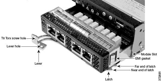
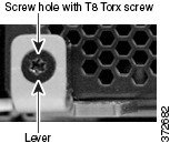
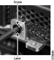
Figure C-5 Sample Module Lever (closed with screw in hole)
Before You Begin
Prepare to insert or remove your module using the following guidelines:

Tip![]() You can insert the NetMod into any available, compatible slot.
You can insert the NetMod into any available, compatible slot.
- Identify the correct slots for your stacking modules. See Using Devices in a Stacked Configuration.
- Firepower 8140: slot 3
- Firepower 8250, 8260 and 8350, 8360 primary slot: slot 5
- Firepower 8270 and 8370 primary slots: slots 5 and 1
- Firepower 8290 and 8390 primary slots: slots 5, 1, and 4
- Firepower 82xx and 83xx secondary: slot S
- Confirm that the EMI gaskets are in place.
- Unplug all power cords from the appliance.
Removing a Module or Slot Cover
Use proper electrostatic discharge (ESD) practices such as wearing wrist straps and using an ESD work surface when handling the modules. Store unused modules in an ESD bag or box to prevent damage.
To remove a module or slot cover:
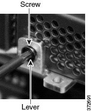
Step 1![]() Remove and reserve the T8 Torx screw from the lever of the module using the included screwdriver.
Remove and reserve the T8 Torx screw from the lever of the module using the included screwdriver.
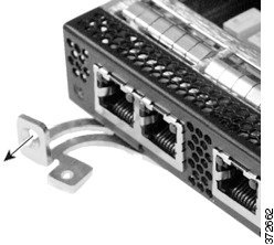
Step 2![]() Pull the lever away from the module to release the latch.
Pull the lever away from the module to release the latch.
Step 3![]() Slide the module out of the slot.
Slide the module out of the slot.
Inserting a Module or Slot Cover
- Remove the existing module or slot cover to prepare the slot for a new module. See Removing a Module or Slot Cover for more information.
To insert a module or slot cover:
Step 1![]() Remove and reserve the T8 Torx screw from the lever of the module using the included screwdriver.
Remove and reserve the T8 Torx screw from the lever of the module using the included screwdriver.
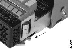
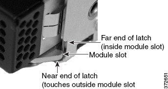
Step 2![]() Pull the lever away from the module to open the latch. The near end of the latch is visible. The far end of the latch is inside the module.
Pull the lever away from the module to open the latch. The near end of the latch is visible. The far end of the latch is inside the module.
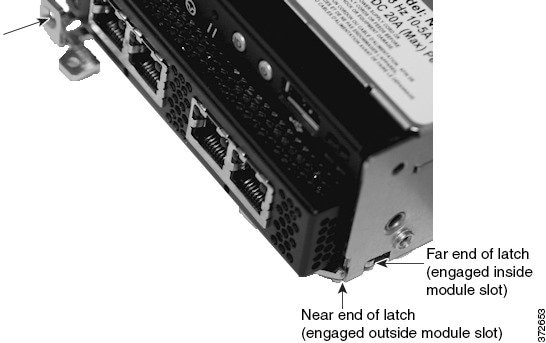
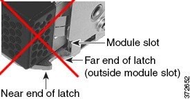
Step 3![]() Insert the module into the slot until the far end of the latch is inside the slot and the near end of the latch touches the outside of the module slot.
Insert the module into the slot until the far end of the latch is inside the slot and the near end of the latch touches the outside of the module slot.
Step 4![]() Push the lever toward the module so that the latch engages and pulls the module into the slot.
Push the lever toward the module so that the latch engages and pulls the module into the slot.
Step 5![]() Press firmly on the screw hole to push the lever fully against the module to secure the latch.
Press firmly on the screw hole to push the lever fully against the module to secure the latch.
The lever is fully against the module, and the module is flush with the chassis.
Step 6![]() Insert and tighten the reserved T8 Torx screw into the lever.
Insert and tighten the reserved T8 Torx screw into the lever.

 Feedback