ASDM Book 2: Cisco ASA Series Firewall ASDM Configuration Guide, 7.2
Bias-Free Language
The documentation set for this product strives to use bias-free language. For the purposes of this documentation set, bias-free is defined as language that does not imply discrimination based on age, disability, gender, racial identity, ethnic identity, sexual orientation, socioeconomic status, and intersectionality. Exceptions may be present in the documentation due to language that is hardcoded in the user interfaces of the product software, language used based on RFP documentation, or language that is used by a referenced third-party product. Learn more about how Cisco is using Inclusive Language.
- Updated:
- March 17, 2014
Chapter: Twice NAT
Twice NAT (ASA 8.3 and Later)
Twice NAT lets you identify both the source and destination address in a single rule. This chapter shows you how to configure twice NAT and includes the following sections:
- Information About Twice NAT
- Licensing Requirements for Twice NAT
- Prerequisites for Twice NAT
- Guidelines and Limitations
- Default Settings
- Configuring Twice NAT
- Monitoring Twice NAT
- Configuration Examples for Twice NAT
- Feature History for Twice NAT

Note![]() For detailed information about how NAT works, see Chapter5, “Information About NAT (ASA 8.3 and Later)”
For detailed information about how NAT works, see Chapter5, “Information About NAT (ASA 8.3 and Later)”
Information About Twice NAT
Twice NAT lets you identify both the source and destination address in a single rule. Specifying both the source and destination addresses lets you specify that a source address should be translated to A when going to destination X, but be translated to B when going to destination Y, for example.
Note![]() For static NAT, the rule is bidirectional, so be aware that “source” and “destination” are used in commands and descriptions throughout this guide even though a given connection might originate at the “destination” address. For example, if you configure static NAT with port address translation, and specify the source address as a Telnet server, and you want all traffic going to that Telnet server to have the port translated from 2323 to 23, then in the command, you must specify the source ports to be translated (real: 23, mapped: 2323). You specify the source ports because you specified the Telnet server address as the source address.
For static NAT, the rule is bidirectional, so be aware that “source” and “destination” are used in commands and descriptions throughout this guide even though a given connection might originate at the “destination” address. For example, if you configure static NAT with port address translation, and specify the source address as a Telnet server, and you want all traffic going to that Telnet server to have the port translated from 2323 to 23, then in the command, you must specify the source ports to be translated (real: 23, mapped: 2323). You specify the source ports because you specified the Telnet server address as the source address.
The destination address is optional. If you specify the destination address, you can either map it to itself (identity NAT), or you can map it to a different address. The destination mapping is always a static mapping.
Twice NAT also lets you use service objects for static NAT-with-port-translation; network object NAT only accepts inline definition.
For detailed information about the differences between twice NAT and network object NAT, see How NAT is Implemented.
Twice NAT rules are added to section 1 of the NAT rules table, or if specified, section 3. For more information about NAT ordering, see NAT Rule Order.
Licensing Requirements for Twice NAT
|
|
|
|---|---|
Prerequisites for Twice NAT
- For both the real and mapped addresses, configure network objects or network object groups. Network object groups are particularly useful for creating a mapped address pool with discontinuous IP address ranges or multiple hosts or subnets. To create a network object or group, see the general operations configuration guide.
- For static NAT-with-port-translation, configure TCP or UDP service objects. To create a service object, see the general operations configuration guide.
For specific guidelines for objects and groups, see the configuration section for the NAT type you want to configure. See also the Guidelines and Limitations section.
Guidelines and Limitations
This section includes the guidelines and limitations for this feature.
Supported in single and multiple context mode.
- Supported in routed and transparent firewall mode.
- In transparent mode, you must specify the real and mapped interfaces; you cannot use --Any--.
- In transparent mode, you cannot configure interface PAT, because the transparent mode interfaces do not have IP addresses. You also cannot use the management IP address as a mapped address.
- In transparent mode, translating between IPv4 and IPv6 networks is not supported. Translating between two IPv6 networks, or between two IPv4 networks is supported.
- Supports IPv6.
- For routed mode, you can also translate between IPv4 and IPv6.
- For transparent mode, translating between IPv4 and IPv6 networks is not supported. Translating between two IPv6 networks, or between two IPv4 networks is supported.
- For transparent mode, a PAT pool is not supported for IPv6.
- For static NAT, you can specify an IPv6 subnet up to /64. Larger subnets are not supported.
- When using FTP with NAT46, when an IPv4 FTP client connects to an IPv6 FTP server, the client must use either the extended passive mode (EPSV) or extended port mode (EPRT); PASV and PORT commands are not supported with IPv6.
- You cannot configure FTP destination port translation when the source IP address is a subnet (or any other application that uses a secondary connection); the FTP data channel establishment does not succeed.
- If you change the NAT configuration, and you do not want to wait for existing translations to time out before the new NAT information is used, you can clear the translation table using the clear xlate command. However, clearing the translation table disconnects all current connections that use translations.
Note![]() If you remove a dynamic NAT or PAT rule, and then add a new rule with mapped addresses that overlap the addresses in the removed rule, then the new rule will not be used until all connections associated with the removed rule time out or are cleared using the clear xlate command. This safeguard ensures that the same address is not assigned to multiple hosts.
If you remove a dynamic NAT or PAT rule, and then add a new rule with mapped addresses that overlap the addresses in the removed rule, then the new rule will not be used until all connections associated with the removed rule time out or are cleared using the clear xlate command. This safeguard ensures that the same address is not assigned to multiple hosts.
- You cannot use an object group with both IPv4 and IPv6 addresses; the object group must include only one type of address.
- When using the any keyword in a NAT rule, the definition of “any” traffic (IPv4 vs. IPv6) depends on the rule. Before the ASA performs NAT on a packet, the packet must be IPv6-to-IPv6 or IPv4-to-IPv4; with this prerequisite, the ASA can determine the value of any in a NAT rule. For example, if you configure a rule from “any” to an IPv6 server, and that server was mapped from an IPv4 address, then any means “any IPv6 traffic.” If you configure a rule from “any” to “any,” and you map the source to the interface IPv4 address, then any means “any IPv4 traffic” because the mapped interface address implies that the destination is also IPv4.
- Objects and object groups used in NAT cannot be undefined; they must include IP addresses.
- You can use the same objects in multiple rules.
- The mapped IP address pool cannot include:
–![]() The mapped interface IP address. If you specify --Any-- interface for the rule, then all interface IP addresses are disallowed. For interface PAT (routed mode only), use the interface name instead of the IP address.
The mapped interface IP address. If you specify --Any-- interface for the rule, then all interface IP addresses are disallowed. For interface PAT (routed mode only), use the interface name instead of the IP address.
–![]() (Transparent mode) The management IP address.
(Transparent mode) The management IP address.
–![]() (Dynamic NAT) The standby interface IP address when VPN is enabled.
(Dynamic NAT) The standby interface IP address when VPN is enabled.
Default Settings
- By default, the rule is added to the end of section 1 of the NAT table.
- (Routed mode) The default real and mapped interface is Any, which applies the rule to all interfaces.
- (8.3(1), 8.3(2), and 8.4(1)) The default behavior for identity NAT has proxy ARP disabled. You cannot configure this setting. (8.4(2) and later) The default behavior for identity NAT has proxy ARP enabled, matching other static NAT rules. You can disable proxy ARP if desired.
- If you specify an optional interface, then the ASA uses the NAT configuration to determine the egress interface. (8.3(1) through 8.4(1)) The only exception is for identity NAT, which always uses a route lookup, regardless of the NAT configuration. (8.4(2) and later) For identity NAT, the default behavior is to use the NAT configuration, but you have the option to always use a route lookup instead.
Configuring Twice NAT
This section describes how to configure twice NAT. This section includes the following topics:
- Configuring Dynamic NAT or Dynamic PAT Using a PAT Pool
- Configuring Dynamic PAT (Hide)
- Configuring Static NAT or Static NAT-with-Port-Translation
- Configuring Identity NAT
- Configuring Per-Session PAT Rules
Configuring Dynamic NAT or Dynamic PAT Using a PAT Pool
This section describes how to configure twice NAT for dynamic NAT or for dynamic PAT using a PAT pool. For more information, see Dynamic NAT or the Dynamic PAT.
Guidelines
- If available, the real source port number is used for the mapped port. However, if the real port is not available, by default the mapped ports are chosen from the same range of ports as the real port number: 0 to 511, 512 to 1023, and 1024 to 65535. Therefore, ports below 1024 have only a small PAT pool that can be used. (8.4(3) and later, not including 8.5(1) or 8.6(1)) If you have a lot of traffic that uses the lower port ranges, you can now specify for a PAT pool a flat range of ports to be used instead of the three unequal-sized tiers: either 1024 to 65535, or 1 to 65535.
- (8.4(3) and later, not including 8.5(1) or 8.6(1)) If you use the same PAT pool object in two separate rules, then be sure to specify the same options for each rule. For example, if one rule specifies extended PAT and a flat range, then the other rule must also specify extended PAT and a flat range.
For extended PAT for a PAT pool (8.4(3) and later, not including 8.5(1) or 8.6(1)):
- Many application inspections do not support extended PAT. See Default Settings and NAT Limitations in “Getting Started with Application Layer Protocol Inspection,” for a complete list of unsupported inspections.
- If you enable extended PAT for a dynamic PAT rule, then you cannot also use an address in the PAT pool as the PAT address in a separate static NAT with port translation rule. For example, if the PAT pool includes 10.1.1.1, then you cannot create a static NAT-with-port-translation rule using 10.1.1.1 as the PAT address.
- Extended PAT can consume a large amount of memory because NAT pools are created for each unique destination, which in turn uses up memory. This may lead to memory exhaustion quickly even with less number of connections.
- If you use a PAT pool and specify an interface for fallback, you cannot specify extended PAT.
- For VoIP deployments that use ICE or TURN, do not use extended PAT. ICE and TURN rely on the PAT binding to be the same for all destinations.
For round robin for a PAT pool:
- (8.4(3) and later, not including 8.5(1) or 8.6(1)) If a host has an existing connection, then subsequent connections from that host will use the same PAT IP address if ports are available. Note : This “stickiness” does not survive a failover. If the ASA fails over, then subsequent connections from a host may not use the initial IP address.
- (8.4(2), 8.5(1), and 8.6(1)) If a host has an existing connection, then subsequent connections from that host will likely use different PAT addresses for each connection because of the round robin allocation. In this case, you may have problems when accessing two websites that exchange information about the host, for example an e-commerce site and a payment site. When these sites see two different IP addresses for what is supposed to be a single host, the transaction may fail.
- Round robin, especially when combined with extended PAT, can consume a large amount of memory. Because NAT pools are created for every mapped protocol/IP address/port range, round robin results in a large number of concurrent NAT pools, which use memory. Extended PAT results in an even larger number of concurrent NAT pools.
Detailed Steps
To configure dynamic NAT, perform the following steps:
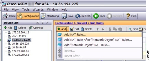
Step 1![]() Choose Configuration > Firewall > NAT Rules, and then click Add.
Choose Configuration > Firewall > NAT Rules, and then click Add.
If you want to add this rule to section 3 after the network object rules, then click the down arrow next to Add, and choose Add NAT Rule After Network Object NAT Rules.
The Add NAT Rule dialog box appears.

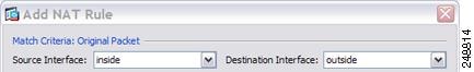
Step 2![]() Set the source and destination interfaces.
Set the source and destination interfaces.
By default in routed mode, both interfaces are set to --Any--. In transparent firewall mode, you must set specific interfaces.
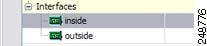
a.![]() From the Match Criteria: Original Packet > Source Interface drop-down list, choose the source interface.
From the Match Criteria: Original Packet > Source Interface drop-down list, choose the source interface.
b.![]() From the Match Criteria: Original Packet > Destination Interface drop-down list, choose the destination interface.
From the Match Criteria: Original Packet > Destination Interface drop-down list, choose the destination interface.
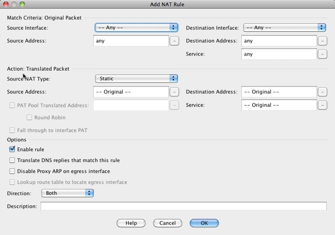
Step 3![]() Identify the original packet addresses, either IPv4 or IPv6; namely, the packet addresses as they appear on the source interface network (the real source address and the mapped destination address). See the following figure for an example of the original packet vs. the translated packet.
Identify the original packet addresses, either IPv4 or IPv6; namely, the packet addresses as they appear on the source interface network (the real source address and the mapped destination address). See the following figure for an example of the original packet vs. the translated packet.

a.![]() For the Match Criteria: Original Packet > Source Address, click the browse button and choose an existing network object or group or create a new object or group from the Browse Original Source Address dialog box. The group cannot contain both IPv4 and IPv6 addresses; it must contain one type only. The default is any.
For the Match Criteria: Original Packet > Source Address, click the browse button and choose an existing network object or group or create a new object or group from the Browse Original Source Address dialog box. The group cannot contain both IPv4 and IPv6 addresses; it must contain one type only. The default is any.
b.![]() (Optional) For the Match Criteria: Original Packet > Destination Address, click the browse button and choose an existing network object or group or create a new object or group from the Browse Original Destination Address dialog box. The group cannot contain both IPv4 and IPv6 addresses; it must contain one type only.
(Optional) For the Match Criteria: Original Packet > Destination Address, click the browse button and choose an existing network object or group or create a new object or group from the Browse Original Destination Address dialog box. The group cannot contain both IPv4 and IPv6 addresses; it must contain one type only.
Although the main feature of twice NAT is the inclusion of the destination IP address, the destination address is optional. If you do specify the destination address, you can configure static translation for that address or just use identity NAT for it. You might want to configure twice NAT without a destination address to take advantage of some of the other qualities of twice NAT, including the use of network object groups for real addresses, or manually ordering of rules. For more information, see Main Differences Between Network Object NAT and Twice NAT.
Step 4![]() (Optional) Identify the original packet port (the mapped destination port). For the Match Criteria: Original Packet > Service, click the browse button and choose an existing TCP or UDP service object or create a new object from the Browse Original Service dialog box.
(Optional) Identify the original packet port (the mapped destination port). For the Match Criteria: Original Packet > Service, click the browse button and choose an existing TCP or UDP service object or create a new object from the Browse Original Service dialog box.
Dynamic NAT does not support port translation. However, because the destination translation is always static, you can perform port translation for the destination port. A service object can contain both a source and destination port, but only the destination port is used in this case. If you specify the source port, it will be ignored. NAT only supports TCP or UDP. When translating a port, be sure the protocols in the real and mapped service objects are identical (both TCP or both UDP). For identity NAT, you can use the same service object for both the real and mapped ports. The “not equal” (!=) operator is not supported.

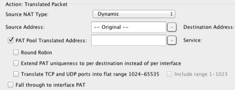
Step 5![]() Choose Dynamic from the Match Criteria: Translated Packet > Source NAT Type drop-down list.
Choose Dynamic from the Match Criteria: Translated Packet > Source NAT Type drop-down list.
This setting only applies to the source address; the destination translation is always static.

Step 6![]() Identify the translated packet addresses, either IPv4 or IPv6; namely, the packet addresses as they appear on the destination interface network (the mapped source address and the real destination address). You can translate between IPv4 and IPv6 if desired. See the following figure for an example of the original packet vs. the translated packet.
Identify the translated packet addresses, either IPv4 or IPv6; namely, the packet addresses as they appear on the destination interface network (the mapped source address and the real destination address). You can translate between IPv4 and IPv6 if desired. See the following figure for an example of the original packet vs. the translated packet.
a.![]() You can perform either dynamic NAT or Dynamic PAT using a PAT pool:
You can perform either dynamic NAT or Dynamic PAT using a PAT pool:
For dynamic NAT, you typically configure a larger group of source addresses to be mapped to a smaller group.
Note![]() The object or group cannot contain a subnet.
The object or group cannot contain a subnet.
- Dynamic PAT using a PAT pool—.To configure a PAT pool, check the PAT Pool Translated Address check box, then click the browse button and choose an existing network object or group or create a new object or group from the Browse Translated PAT Pool Address dialog box. Note : Leave the Source Address field empty.
Note![]() The object or group cannot contain a subnet.
The object or group cannot contain a subnet.
(Optional) For a PAT pool, configure the following options:
–![]() To assign addresses/ports in a round-robin fashion, check the Round Robin check box. Without round-robin, by default, all ports for a PAT address will be allocated before the next PAT address is used. The round-robin method assigns an address/port from each PAT address in the pool before returning to use the first address again, and then the second address, and so on.
To assign addresses/ports in a round-robin fashion, check the Round Robin check box. Without round-robin, by default, all ports for a PAT address will be allocated before the next PAT address is used. The round-robin method assigns an address/port from each PAT address in the pool before returning to use the first address again, and then the second address, and so on.
–![]() (8.4(3) and later, not including 8.5(1) or 8.6(1)) Check the Extend PAT uniqueness to per destination instead of per interface check box to use extended PAT. Extended PAT uses 65535 ports per service, as opposed to per IP address, by including the destination address and port in the translation information. Normally, the destination port and address are not considered when creating PAT translations, so you are limited to 65535 ports per PAT address. For example, with extended PAT, you can create a translation of 10.1.1.1:1027 when going to 192.168.1.7:23 as well as a translation of 10.1.1.1:1027 when going to 192.168.1.7:80.
(8.4(3) and later, not including 8.5(1) or 8.6(1)) Check the Extend PAT uniqueness to per destination instead of per interface check box to use extended PAT. Extended PAT uses 65535 ports per service, as opposed to per IP address, by including the destination address and port in the translation information. Normally, the destination port and address are not considered when creating PAT translations, so you are limited to 65535 ports per PAT address. For example, with extended PAT, you can create a translation of 10.1.1.1:1027 when going to 192.168.1.7:23 as well as a translation of 10.1.1.1:1027 when going to 192.168.1.7:80.
–![]() (8.4(3) and later, not including 8.5(1) or 8.6(1)) Check the Translate TCP or UDP ports into flat range (1024-65535) check box to use the 1024 to 65535 port range as a single flat range when allocating ports. When choosing the mapped port number for a translation, the ASA uses the real source port number if it is available. However, without this option, if the real port is not available, by default the mapped ports are chosen from the same range of ports as the real port number: 1 to 511, 512 to 1023, and 1024 to 65535. To avoid running out of ports at the low ranges, configure this setting. To use the entire range of 1 to 65535, also check the Include range 1 to 1023 check box.
(8.4(3) and later, not including 8.5(1) or 8.6(1)) Check the Translate TCP or UDP ports into flat range (1024-65535) check box to use the 1024 to 65535 port range as a single flat range when allocating ports. When choosing the mapped port number for a translation, the ASA uses the real source port number if it is available. However, without this option, if the real port is not available, by default the mapped ports are chosen from the same range of ports as the real port number: 1 to 511, 512 to 1023, and 1024 to 65535. To avoid running out of ports at the low ranges, configure this setting. To use the entire range of 1 to 65535, also check the Include range 1 to 1023 check box.
b.![]() (Optional, Routed Mode Only) To use the interface IP address as a backup method if the other mapped source addresses are already allocated, check the Fall through to interface PAT check box. To use the IPv6 interface address, also check the Use IPv6 for interface PAT check box.
(Optional, Routed Mode Only) To use the interface IP address as a backup method if the other mapped source addresses are already allocated, check the Fall through to interface PAT check box. To use the IPv6 interface address, also check the Use IPv6 for interface PAT check box.
The destination interface IP address is used. This option is only available if you configure a specific Destination Interface.

c.![]() For the Match Criteria: Translated Packet > Destination Address, click the browse button and choose an existing network object, group, or interface or create a new object or group from the Browse Translated Destination Address dialog box.
For the Match Criteria: Translated Packet > Destination Address, click the browse button and choose an existing network object, group, or interface or create a new object or group from the Browse Translated Destination Address dialog box.
For identity NAT for the destination address, simply use the same object or group for both the real and mapped addresses.
If you want to translate the destination address, then the static mapping is typically one-to-one, so the real addresses have the same quantity as the mapped addresses. You can, however, have different quantities if desired. For more information, see Static NAT. See Guidelines and Limitations for information about disallowed mapped IP addresses.
For static interface NAT with port translation only, choose an interface from the Browse dialog box. Be sure to also configure a service translation (see Step 7). For this option, you must configure a specific interface for the Source Interface in Step 2. See Static Interface NAT with Port Translation for more information.
Step 7![]() (Optional) Identify the translated packet port (the real destination port). For the Match Criteria: Translated Packet > Service, click the browse button and choose an existing TCP or UDP service object or create a new object from the Browse Translated Service dialog box.
(Optional) Identify the translated packet port (the real destination port). For the Match Criteria: Translated Packet > Service, click the browse button and choose an existing TCP or UDP service object or create a new object from the Browse Translated Service dialog box.
Dynamic NAT does not support port translation. However, because the destination translation is always static, you can perform port translation for the destination port. A service object can contain both a source and destination port, but only the destination port is used in this case. If you specify the source port, it will be ignored. NAT only supports TCP or UDP. When translating a port, be sure the protocols in the real and mapped service objects are identical (both TCP or both UDP). For identity NAT, you can use the same service object for both the real and mapped ports. The “not equal” (!=) operator is not supported.
Step 8![]() (Optional) Configure NAT options in the Options area.
(Optional) Configure NAT options in the Options area.

a.![]() Enable rule —Enables this NAT rule. The rule is enabled by default.
Enable rule —Enables this NAT rule. The rule is enabled by default.
b.![]() (For a source-only rule) Translate DNS replies that match this rule—Rewrites the DNS A record in DNS replies. Be sure DNS inspection is enabled (it is enabled by default). You cannot configure DNS modification if you configure a destination address. See DNS and NAT for more information.
(For a source-only rule) Translate DNS replies that match this rule—Rewrites the DNS A record in DNS replies. Be sure DNS inspection is enabled (it is enabled by default). You cannot configure DNS modification if you configure a destination address. See DNS and NAT for more information.
c.![]() Description—Adds a description about the rule up to 200 characters in length.
Description—Adds a description about the rule up to 200 characters in length.
Configuring Dynamic PAT (Hide)
This section describes how to configure twice NAT for dynamic PAT (hide). For dynamic PAT using a PAT pool, see Configuring Dynamic NAT or Dynamic PAT Using a PAT Pool instead of using this section. For more information, see Dynamic PAT.
Detailed Steps
To configure dynamic PAT, perform the following steps:
Step 1![]() Choose Configuration > Firewall > NAT Rules, and then click Add.
Choose Configuration > Firewall > NAT Rules, and then click Add.
If you want to add this rule to section 3 after the network object rules, then click the down arrow next to Add, and choose Add NAT Rule After Network Object NAT Rules.
The Add NAT Rule dialog box appears.
Step 2![]() Set the source and destination interfaces.
Set the source and destination interfaces.
By default in routed mode, both interfaces are set to --Any--. In transparent firewall mode, you must set specific interfaces.
a.![]() From the Match Criteria: Original Packet > Source Interface drop-down list, choose the source interface.
From the Match Criteria: Original Packet > Source Interface drop-down list, choose the source interface.
b.![]() From the Match Criteria: Original Packet > Destination Interface drop-down list, choose the destination interface.
From the Match Criteria: Original Packet > Destination Interface drop-down list, choose the destination interface.
Step 3![]() Identify the original packet addresses, either IPv4 or IPv6; namely, the packet addresses as they appear on the source interface network (the real source address and the mapped destination address). See the following figure for an example of the original packet vs. the translated packet.
Identify the original packet addresses, either IPv4 or IPv6; namely, the packet addresses as they appear on the source interface network (the real source address and the mapped destination address). See the following figure for an example of the original packet vs. the translated packet.
a.![]() For the Match Criteria: Original Packet > Source Address, click the browse button and choose an existing network object or group or create a new object or group from the Browse Original Source Address dialog box. The group cannot contain both IPv4 and IPv6 addresses; it must contain one type only. The default is any.
For the Match Criteria: Original Packet > Source Address, click the browse button and choose an existing network object or group or create a new object or group from the Browse Original Source Address dialog box. The group cannot contain both IPv4 and IPv6 addresses; it must contain one type only. The default is any.
b.![]() (Optional) For the Match Criteria: Original Packet > Destination Address, click the browse button
(Optional) For the Match Criteria: Original Packet > Destination Address, click the browse button  and choose an existing network object or group or create a new object or group from the Browse Original Destination Address dialog box. The group cannot contain both IPv4 and IPv6 addresses; it must contain one type only.
Although the main feature of twice NAT is the inclusion of the destination IP address, the destination address is optional. If you do specify the destination address, you can configure static translation for that address or just use identity NAT for it. You might want to configure twice NAT without a destination address to take advantage of some of the other qualities of twice NAT, including the use of network object groups for real addresses, or manually ordering of rules. For more information, see Main Differences Between Network Object NAT and Twice NAT.
Step 4![]() (Optional) Identify the original packet port (the mapped destination port). For the Match Criteria: Original Packet > Service, click the browse button and choose an existing TCP or UDP service object or create a new object from the Browse Original Service dialog box.
(Optional) Identify the original packet port (the mapped destination port). For the Match Criteria: Original Packet > Service, click the browse button and choose an existing TCP or UDP service object or create a new object from the Browse Original Service dialog box.
Dynamic PAT does not support additional port translation. However, because the destination translation is always static, you can perform port translation for the destination port. A service object can contain both a source and destination port, but only the destination port is used in this case. If you specify the source port, it will be ignored. NAT only supports TCP or UDP. When translating a port, be sure the protocols in the real and mapped service objects are identical (both TCP or both UDP). For identity NAT, you can use the same service object for both the real and mapped ports. The “not equal” (!=) operator is not supported.
Step 5![]() Choose Dynamic PAT (Hide) from the Match Criteria: Translated Packet > Source NAT Type drop-down list.
Choose Dynamic PAT (Hide) from the Match Criteria: Translated Packet > Source NAT Type drop-down list.
This setting only applies to the source address; the destination translation is always static.
Note![]() To configure dynamic PAT using a PAT pool, choose Dynamic instead of Dynamic PAT (Hide), see Configuring Dynamic NAT or Dynamic PAT Using a PAT Pool.
To configure dynamic PAT using a PAT pool, choose Dynamic instead of Dynamic PAT (Hide), see Configuring Dynamic NAT or Dynamic PAT Using a PAT Pool.

Step 6![]() Identify the translated packet addresses, either IPv4 or IPv6; namely, the packet addresses as they appear on the destination interface network (the mapped source address and the real destination address). You can translate between IPv4 and IPv6 if desired. See the following figure for an example of the original packet vs. the translated packet.
Identify the translated packet addresses, either IPv4 or IPv6; namely, the packet addresses as they appear on the destination interface network (the mapped source address and the real destination address). You can translate between IPv4 and IPv6 if desired. See the following figure for an example of the original packet vs. the translated packet.
a.![]() For the Match Criteria: Translated Packet > Source Address, click the browse button and choose an existing network object or interface or create a new object from the Browse Translated Source Address dialog box.
For the Match Criteria: Translated Packet > Source Address, click the browse button and choose an existing network object or interface or create a new object from the Browse Translated Source Address dialog box.
If you want to use the IPv6 address of the interface, check the Use IPv6 for interface PAT check box.

b.![]() For the Match Criteria: Translated Packet > Destination Address, click the browse button and choose an existing network object or group or create a new object or group from the Browse Translated Destination Address dialog box. The group cannot contain both IPv4 and IPv6 addresses; it must contain one type only.
For the Match Criteria: Translated Packet > Destination Address, click the browse button and choose an existing network object or group or create a new object or group from the Browse Translated Destination Address dialog box. The group cannot contain both IPv4 and IPv6 addresses; it must contain one type only.
For identity NAT for the destination address, simply use the same object or group for both the real and mapped addresses.
If you want to translate the destination address, then the static mapping is typically one-to-one, so the real addresses have the same quantity as the mapped addresses. You can, however, have different quantities if desired. For more information, see Static NAT. See Guidelines and Limitations for information about disallowed mapped IP addresses.
For static interface NAT with port translation only, choose an interface from the Browse dialog box. Be sure to also configure a service translation (see Step 7). For this option, you must configure a specific interface for the Source Interface in Step 2. See Static Interface NAT with Port Translation for more information.
Step 7![]() (Optional) Identify the translated packet port (the real destination port). For the Match Criteria: Translated Packet > Service, click the browse button and choose an existing TCP or UDP service object from the Browse Translated Service dialog box.
(Optional) Identify the translated packet port (the real destination port). For the Match Criteria: Translated Packet > Service, click the browse button and choose an existing TCP or UDP service object from the Browse Translated Service dialog box.
You can also create a new service object from the Browse Translated Service dialog box and use this object as the mapped destination port.
Dynamic PAT does not support additional port translation. However, because the destination translation is always static, you can perform port translation for the destination port. A service object can contain both a source and destination port, but only the destination port is used in this case. If you specify the source port, it will be ignored. NAT only supports TCP or UDP. When translating a port, be sure the protocols in the real and mapped service objects are identical (both TCP or both UDP). For identity NAT, you can use the same service object for both the real and mapped ports. The “not equal” (!=) operator is not supported.
Step 8![]() (Optional) Configure NAT options in the Options area.
(Optional) Configure NAT options in the Options area.
a.![]() Enable rule —Enables this NAT rule. The rule is enabled by default.
Enable rule —Enables this NAT rule. The rule is enabled by default.
b.![]() (For a source-only rule) Translate DNS replies that match this rule—Rewrites the DNS A record in DNS replies. Be sure DNS inspection is enabled (it is enabled by default). You cannot configure DNS modification if you configure a destination address. See DNS and NAT for more information.
(For a source-only rule) Translate DNS replies that match this rule—Rewrites the DNS A record in DNS replies. Be sure DNS inspection is enabled (it is enabled by default). You cannot configure DNS modification if you configure a destination address. See DNS and NAT for more information.
c.![]() Description—Adds a description about the rule up to 200 characters in length.
Description—Adds a description about the rule up to 200 characters in length.
Configuring Static NAT or Static NAT-with-Port-Translation
This section describes how to configure a static NAT rule using twice NAT. For more information about static NAT, see Static NAT.
Detailed Steps
To configure static NAT, perform the following steps:
Step 1![]() Choose Configuration > Firewall > NAT Rules, and then click Add.
Choose Configuration > Firewall > NAT Rules, and then click Add.
If you want to add this rule to section 3 after the network object rules, then click the down arrow next to Add, and choose Add NAT Rule After Network Object NAT Rules.
The Add NAT Rule dialog box appears.
Step 2![]() Set the source and destination interfaces.
Set the source and destination interfaces.
By default in routed mode, both interfaces are set to --Any--. In transparent firewall mode, you must set specific interfaces.
a.![]() From the Match Criteria: Original Packet > Source Interface drop-down list, choose the source interface.
From the Match Criteria: Original Packet > Source Interface drop-down list, choose the source interface.
b.![]() From the Match Criteria: Original Packet > Destination Interface drop-down list, choose the destination interface.
From the Match Criteria: Original Packet > Destination Interface drop-down list, choose the destination interface.
Step 3![]() Identify the original packet addresses, either IPv4 or IPv6; namely, the packet addresses as they appear on the source interface network (the real source address and the mapped destination address). See the following figure for an example of the original packet vs. the translated packet.
Identify the original packet addresses, either IPv4 or IPv6; namely, the packet addresses as they appear on the source interface network (the real source address and the mapped destination address). See the following figure for an example of the original packet vs. the translated packet.
a.![]() For the Match Criteria: Original Packet > Source Address, click the browse button and choose an existing network object or group or create a new object or group from the Browse Original Source Address dialog box. The group cannot contain both IPv4 and IPv6 addresses; it must contain one type only. The default is any, but do not use this option except for identity NAT. See Configuring Identity NAT for more information.
For the Match Criteria: Original Packet > Source Address, click the browse button and choose an existing network object or group or create a new object or group from the Browse Original Source Address dialog box. The group cannot contain both IPv4 and IPv6 addresses; it must contain one type only. The default is any, but do not use this option except for identity NAT. See Configuring Identity NAT for more information.
b.![]() (Optional) For the Match Criteria: Original Packet > Destination Address, click the browse button and choose an existing network object or group or create a new object or group from the Browse Original Destination Address dialog box.
(Optional) For the Match Criteria: Original Packet > Destination Address, click the browse button and choose an existing network object or group or create a new object or group from the Browse Original Destination Address dialog box.
Although the main feature of twice NAT is the inclusion of the destination IP address, the destination address is optional. If you do specify the destination address, you can configure static translation for that address or just use identity NAT for it. You might want to configure twice NAT without a destination address to take advantage of some of the other qualities of twice NAT, including the use of network object groups for real addresses, or manually ordering of rules. For more information, see Main Differences Between Network Object NAT and Twice NAT.
Step 4![]() (Optional) Identify the original packet source or destination port (the real source port or the mapped destination port). For the Match Criteria: Original Packet > Service, click the browse button and choose an existing TCP or UDP service object or create a new object from the Browse Original Service dialog box.
(Optional) Identify the original packet source or destination port (the real source port or the mapped destination port). For the Match Criteria: Original Packet > Service, click the browse button and choose an existing TCP or UDP service object or create a new object from the Browse Original Service dialog box.
A service object can contain both a source and destination port. You should specify either the source or the destination port for both the real and mapped service objects. You should only specify both the source and destination ports if your application uses a fixed source port (such as some DNS servers); but fixed source ports are rare. In the rare case where you specify both the source and destination ports in the object, the original packet service object contains the real source port/mapped destination port; the translated packet service object contains the mapped source port/real destination port. NAT only supports TCP or UDP. When translating a port, be sure the protocols in the real and mapped service objects are identical (both TCP or both UDP). For identity NAT, you can use the same service object for both the real and mapped ports. The “not equal” (!=) operator is not supported.
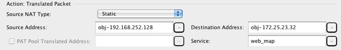
Step 5![]() Choose Static from the Match Criteria: Translated Packet > Source NAT Type drop-down list. Static is the default setting.
Choose Static from the Match Criteria: Translated Packet > Source NAT Type drop-down list. Static is the default setting.
This setting only applies to the source address; the destination translation is always static.

Step 6![]() Identify the translated packet addresses, either IPv4 or IPv6; namely, the packet addresses as they appear on the destination interface network (the mapped source address and the real destination address). You can translate between IPv4 and IPv6 if desired. See the following figure for an example of the original packet vs. the translated packet.
Identify the translated packet addresses, either IPv4 or IPv6; namely, the packet addresses as they appear on the destination interface network (the mapped source address and the real destination address). You can translate between IPv4 and IPv6 if desired. See the following figure for an example of the original packet vs. the translated packet.
a.![]() For the Match Criteria: Translated Packet > Source Address, click the browse button and choose an existing network object or group or create a new object or group from the Browse Translated Source Address dialog box.
For the Match Criteria: Translated Packet > Source Address, click the browse button and choose an existing network object or group or create a new object or group from the Browse Translated Source Address dialog box.
For static NAT, the mapping is typically one-to-one, so the real addresses have the same quantity as the mapped addresses. You can, however, have different quantities if desired.
For static interface NAT with port translation, you can specify the interface instead of a network object/group for the mapped address. If you want to use the IPv6 address of the interface, check the Use IPv6 for interface PAT check box.
For more information, see Static Interface NAT with Port Translation. See Guidelines and Limitations for information about disallowed mapped IP addresses.
b.![]() For the Match Criteria: Translated Packet > Destination Address, click the browse button and choose an existing network object, group, or interface or create a new object or group from the Browse Translated Destination Address dialog box.
For the Match Criteria: Translated Packet > Destination Address, click the browse button and choose an existing network object, group, or interface or create a new object or group from the Browse Translated Destination Address dialog box.
For static NAT, the mapping is typically one-to-one, so the real addresses have the same quantity as the mapped addresses. You can, however, have different quantities if desired.
For static interface NAT with port translation, you can specify the interface instead of a network object/group for the mapped address. For more information, see Static Interface NAT with Port Translation. See Guidelines and Limitations for information about disallowed mapped IP addresses.
Step 7![]() (Optional) Identify the translated packet source or destination port (the mapped source port or the real destination port). For the Match Criteria: Translated Packet > Service, click the browse button and choose an existing TCP or UDP service object or create a new object from the Browse Translated Service dialog box.
(Optional) Identify the translated packet source or destination port (the mapped source port or the real destination port). For the Match Criteria: Translated Packet > Service, click the browse button and choose an existing TCP or UDP service object or create a new object from the Browse Translated Service dialog box.
A service object can contain both a source and destination port. You should specify either the source or the destination port for both real and mapped service objects. You should only specify both the source and destination ports if your application uses a fixed source port (such as some DNS servers); but fixed source ports are rare. In the rare case where you specify both the source and destination ports in the object, the original packet service object contains the real source port/mapped destination port; the translated packet service object contains the mapped source port/real destination port. NAT only supports TCP or UDP. When translating a port, be sure the protocols in the real and mapped service objects are identical (both TCP or both UDP). For identity NAT, you can use the same service object for both the real and mapped ports. The “not equal” (!=) operator is not supported.
Step 8![]() (Optional) For NAT46, check the Use one-to-one address translation check box. For NAT46, specify one-to-one to translate the first IPv4 address to the first IPv6 address, the second to the second, and so on. Without this option, the IPv4-embedded method is used. For a one-to-one translation, you must use this keyword.
(Optional) For NAT46, check the Use one-to-one address translation check box. For NAT46, specify one-to-one to translate the first IPv4 address to the first IPv6 address, the second to the second, and so on. Without this option, the IPv4-embedded method is used. For a one-to-one translation, you must use this keyword.
Step 9![]() (Optional) Configure NAT options in the Options area.
(Optional) Configure NAT options in the Options area.
a.![]() Enable rule —Enables this NAT rule. The rule is enabled by default.
Enable rule —Enables this NAT rule. The rule is enabled by default.
b.![]() (For a source-only rule) Translate DNS replies that match this rule—Rewrites the DNS A record in DNS replies. Be sure DNS inspection is enabled (it is enabled by default). You cannot configure DNS modification if you configure a destination address. See DNS and NAT for more information.
(For a source-only rule) Translate DNS replies that match this rule—Rewrites the DNS A record in DNS replies. Be sure DNS inspection is enabled (it is enabled by default). You cannot configure DNS modification if you configure a destination address. See DNS and NAT for more information.
c.![]() Disable Proxy ARP on egress interface—Disables proxy ARP for incoming packets to the mapped IP addresses. See Mapped Addresses and Routing for more information.
Disable Proxy ARP on egress interface—Disables proxy ARP for incoming packets to the mapped IP addresses. See Mapped Addresses and Routing for more information.
d.![]() Direction—To make the rule unidirectional, choose Unidirectional. The default is Both. Making the rule unidirectional prevents traffic from initiating connections to the real addresses.
Direction—To make the rule unidirectional, choose Unidirectional. The default is Both. Making the rule unidirectional prevents traffic from initiating connections to the real addresses.
e.![]() Description—Adds a description about the rule up to 200 characters in length.
Description—Adds a description about the rule up to 200 characters in length.
Configuring Identity NAT
This section describes how to configure an identity NAT rule using twice NAT. For more information about identity NAT, see Identity NAT.
Detailed Steps
To configure identity NAT, perform the following steps:
Step 1![]() Choose Configuration > Firewall > NAT Rules, and then click Add.
Choose Configuration > Firewall > NAT Rules, and then click Add.
If you want to add this rule to section 3 after the network object rules, then click the down arrow next to Add, and choose Add NAT Rule After Network Object NAT Rules.
The Add NAT Rule dialog box appears.
Step 2![]() Set the source and destination interfaces.
Set the source and destination interfaces.
By default in routed mode, both interfaces are set to --Any--. In transparent firewall mode, you must set specific interfaces.
a.![]() From the Match Criteria: Original Packet > Source Interface drop-down list, choose the source interface.
From the Match Criteria: Original Packet > Source Interface drop-down list, choose the source interface.
b.![]() From the Match Criteria: Original Packet > Destination Interface drop-down list, choose the destination interface.
From the Match Criteria: Original Packet > Destination Interface drop-down list, choose the destination interface.
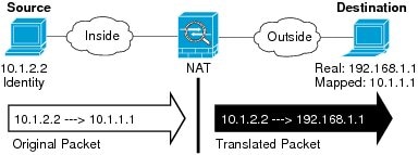
Step 3![]() Identify the original packet addresses, either IPv4 or IPv6; namely, the packet addresses as they appear on the source interface network (the real source address and the mapped destination address). See the following figure for an example of the original packet vs. the translated packet where you perform identity NAT on the inside host but translate the outside host.
Identify the original packet addresses, either IPv4 or IPv6; namely, the packet addresses as they appear on the source interface network (the real source address and the mapped destination address). See the following figure for an example of the original packet vs. the translated packet where you perform identity NAT on the inside host but translate the outside host.
a.![]() For the Match Criteria: Original Packet > Source Address, click the browse button and choose an existing network object or group or create a new object or group from the Browse Original Source Address dialog box. The group cannot contain both IPv4 and IPv6 addresses; it must contain one type only. The default is any ; only use this option when also setting the mapped address to any.
For the Match Criteria: Original Packet > Source Address, click the browse button and choose an existing network object or group or create a new object or group from the Browse Original Source Address dialog box. The group cannot contain both IPv4 and IPv6 addresses; it must contain one type only. The default is any ; only use this option when also setting the mapped address to any.
b.![]() (Optional) For the Match Criteria: Original Packet > Destination Address, click the browse button and choose an existing network object or group or create a new object or group from the Browse Original Destination Address dialog box.
(Optional) For the Match Criteria: Original Packet > Destination Address, click the browse button and choose an existing network object or group or create a new object or group from the Browse Original Destination Address dialog box.
Although the main feature of twice NAT is the inclusion of the destination IP address, the destination address is optional. If you do specify the destination address, you can configure static translation for that address or just use identity NAT for it. You might want to configure twice NAT without a destination address to take advantage of some of the other qualities of twice NAT, including the use of network object groups for real addresses, or manually ordering of rules. For more information, see Main Differences Between Network Object NAT and Twice NAT.
Step 4![]() (Optional) Identify the original packet source or destination port (the real source port or the mapped destination port). For the Match Criteria: Original Packet > Service, click the browse button and choose an existing TCP or UDP service object or create a new object from the Browse Original Service dialog box.
(Optional) Identify the original packet source or destination port (the real source port or the mapped destination port). For the Match Criteria: Original Packet > Service, click the browse button and choose an existing TCP or UDP service object or create a new object from the Browse Original Service dialog box.
A service object can contain both a source and destination port. You should specify either the source or the destination port for both service objects. You should only specify both the source and destination ports if your application uses a fixed source port (such as some DNS servers); but fixed source ports are rare. In the rare case where you specify both the source and destination ports in the object, the original packet service object contains the real source port/mapped destination port; the translated packet service object contains the mapped source port/real destination port. NAT only supports TCP or UDP. When translating a port, be sure the protocols in the real and mapped service objects are identical (both TCP or both UDP). For identity NAT, you can use the same service object for both the real and mapped ports. The “not equal” (!=) operator is not supported.
Step 5![]() Choose Static from the Match Criteria: Translated Packet > Source NAT Type drop-down list. Static is the default setting.
Choose Static from the Match Criteria: Translated Packet > Source NAT Type drop-down list. Static is the default setting.
This setting only applies to the source address; the destination translation is always static.
Step 6![]() Identify the translated packet addresses; namely, the packet addresses as they appear on the destination interface network (the mapped source address and the real destination address). See the following figure for an example of the original packet vs. the translated packet where you perform identity NAT on the inside host but translate the outside host.
Identify the translated packet addresses; namely, the packet addresses as they appear on the destination interface network (the mapped source address and the real destination address). See the following figure for an example of the original packet vs. the translated packet where you perform identity NAT on the inside host but translate the outside host.
a.![]() For the Match Criteria: Translated Packet > Source Address, click the browse button and choose the same network object or group from the Browse Translated Source Address dialog box that you chose for the real source address. Use any if you specified any for the real address.
For the Match Criteria: Translated Packet > Source Address, click the browse button and choose the same network object or group from the Browse Translated Source Address dialog box that you chose for the real source address. Use any if you specified any for the real address.
b.![]() For the Match Criteria: Translated Packet > Destination Address, click the browse button and choose an existing network object, group, or interface or create a new object or group from the Browse Translated Destination Address dialog box.
For the Match Criteria: Translated Packet > Destination Address, click the browse button and choose an existing network object, group, or interface or create a new object or group from the Browse Translated Destination Address dialog box.
For identity NAT for the destination address, simply use the same object or group for both the real and mapped addresses.
If you want to translate the destination address, then the static mapping is typically one-to-one, so the real addresses have the same quantity as the mapped addresses. You can, however, have different quantities if desired. For more information, see Static NAT. See Guidelines and Limitations for information about disallowed mapped IP addresses.
For static interface NAT with port translation only, choose an interface. If you specify an interface, be sure to also configure a a service translation. For more information, see Static Interface NAT with Port Translation.
Step 7![]() (Optional) Identify the translated packet source or destination port (the mapped source port or the real destination port). For the Match Criteria: Translated Packet > Service, click the browse button and choose an existing TCP or UDP service object or create a new object from the Browse Translated Service dialog box.
(Optional) Identify the translated packet source or destination port (the mapped source port or the real destination port). For the Match Criteria: Translated Packet > Service, click the browse button and choose an existing TCP or UDP service object or create a new object from the Browse Translated Service dialog box.
A service object can contain both a source and destination port. You should specify either the source or the destination port for both service objects. You should only specify both the source and destination ports if your application uses a fixed source port (such as some DNS servers); but fixed source ports are rare. In the rare case where you specify both the source and destination ports in the object, the original packet service object contains the real source port/mapped destination port; the translated packet service object contains the mapped source port/real destination port. NAT only supports TCP or UDP. When translating a port, be sure the protocols in the real and mapped service objects are identical (both TCP or both UDP). For identity NAT, you can use the same service object for both the real and mapped ports. The “not equal” (!=) operator is not supported.
Step 8![]() (Optional) Configure NAT options in the Options area.
(Optional) Configure NAT options in the Options area.
a.![]() Enable rule —Enables this NAT rule. The rule is enabled by default.
Enable rule —Enables this NAT rule. The rule is enabled by default.
b.![]() Disable Proxy ARP on egress interface—Disables proxy ARP for incoming packets to the mapped IP addresses. See Mapped Addresses and Routing for more information.
Disable Proxy ARP on egress interface—Disables proxy ARP for incoming packets to the mapped IP addresses. See Mapped Addresses and Routing for more information.
c.![]() (Routed mode; interface(s) specified) Lookup route table to locate egress interface—Determines the egress interface using a route lookup instead of using the interface specified in the NAT command. See Determining the Egress Interface for more information.
(Routed mode; interface(s) specified) Lookup route table to locate egress interface—Determines the egress interface using a route lookup instead of using the interface specified in the NAT command. See Determining the Egress Interface for more information.
d.![]() Direction—To make the rule unidirectional, choose Unidirectional. The default is Both. Making the rule unidirectional prevents traffic from initiating connections to the real addresses. You might want to use this setting for testing purposes.
Direction—To make the rule unidirectional, choose Unidirectional. The default is Both. Making the rule unidirectional prevents traffic from initiating connections to the real addresses. You might want to use this setting for testing purposes.
e.![]() Description—Adds a description about the rule up to 200 characters in length.
Description—Adds a description about the rule up to 200 characters in length.
Note![]() Although the “Translate DNS replies that match this rule” check box is available if you do not configure a destination address, this option is not applicable to identity NAT because you are translating the address to itself, so the DNS reply does not need modification. See DNS and NAT for more information.
Although the “Translate DNS replies that match this rule” check box is available if you do not configure a destination address, this option is not applicable to identity NAT because you are translating the address to itself, so the DNS reply does not need modification. See DNS and NAT for more information.
Configuring Per-Session PAT Rules
By default, all TCP PAT traffic and all UDP DNS traffic uses per-session PAT. To use multi-session PAT for traffic, you can configure per-session PAT rules: a permit rule uses per-session PAT, and a deny rule uses multi-session PAT. For more information about per-session vs. multi-session PAT, see Per-Session PAT vs. Multi-Session PAT (Version 9.0(1) and Later).
Detailed Steps
To configure a per-session PAT rule, see Configuring Per-Session PAT Rules.
Monitoring Twice NAT
The Monitoring > Properties > Connection Graphs > Xlates pane lets you view the active Network Address Translations in a graphical format. You can choose up to four types of statistics to show in one graph window. You can open multiple graph windows at the same time.
–![]() Xlate Utilization—Displays the ASA NAT utilization.
Xlate Utilization—Displays the ASA NAT utilization.
- Graph Window Title—Shows the graph window name to which you want to add a graph type. To use an existing window title, select one from the drop-down list. To display graphs in a new window, enter a new window title.
- Add—Click to move the selected entries in the Available Graphs list to the Selected Graphs list.
- Remove—Click to remove the selected entry from the Selected Graphs list.
- Show Graphs—Click to display a new or updated graph window.
The Monitoring > Properties > Connection Graphs > Perfmon pane lets you view the performance information in a graphical format. You can choose up to four types of statistics to show in one graph window. You can open multiple graph windows at the same time.
–![]() AAA Perfmon—Displays the ASA AAA performance information.
AAA Perfmon—Displays the ASA AAA performance information.
–![]() Inspection Perfmon—Displays the ASA inspection performance information.
Inspection Perfmon—Displays the ASA inspection performance information.
–![]() Web Perfmon—Displays the ASA web performance information, including URL access and URL server requests.
Web Perfmon—Displays the ASA web performance information, including URL access and URL server requests.
–![]() Connections Perfmon—Displays the ASA connections performance information.
Connections Perfmon—Displays the ASA connections performance information.
–![]() Xlate Perfmon—Displays the ASA NAT performance information.
Xlate Perfmon—Displays the ASA NAT performance information.
- Graph Window Title—Shows the graph window name to which you want to add a graph type. To use an existing window title, select one from the drop-down list. To display graphs in a new window, enter a new window title.
- Add—Click to move the selected entries in the Available Graphs list to the Selected Graphs list.
- Remove—Click to remove the selected statistic type from the Selected Graphs list.
- Show Graphs—Click to display a new or updated graph window.
Configuration Examples for Twice NAT
This section includes the following configuration examples:
- Different Translation Depending on the Destination (Dynamic PAT)
- Different Translation Depending on the Destination Address and Port (Dynamic PAT)
Different Translation Depending on the Destination (Dynamic PAT)
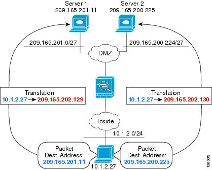
Figure 7-1 shows a host on the 10.1.2.0/24 network accessing two different servers. When the host accesses the server at 209.165.201.11, the real address is translated to 209.165.202.129: port. When the host accesses the server at 209.165.200.225, the real address is translated to 209.165.202.130: port.
Figure 7-1 Twice NAT with Different Destination Addresses
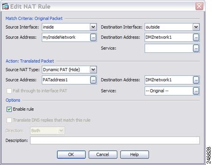
Step 1![]() Add a NAT rule for traffic from the inside network to DMZ network 1:
Add a NAT rule for traffic from the inside network to DMZ network 1:
By default, the NAT rule is added to the end of section 1. If you want to add a NAT rule to section 3, after the network object NAT rules, choose Add NAT Rule After Network Object NAT Rules.
The Add NAT Rule dialog box appears.
Step 2![]() Set the source and destination interfaces:
Set the source and destination interfaces:

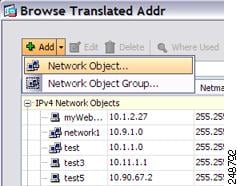
Step 3![]() For the Original Source Address, click the browse button to add a new network object for the inside network in the Browse Original Source Address dialog box.
For the Original Source Address, click the browse button to add a new network object for the inside network in the Browse Original Source Address dialog box.
a.![]() Add the new network object.
Add the new network object.
b.![]() Define the inside network addresses, and click OK.
Define the inside network addresses, and click OK.

c.![]() Choose the new network object by double-clicking it. Click OK to return to the NAT configuration.
Choose the new network object by double-clicking it. Click OK to return to the NAT configuration.
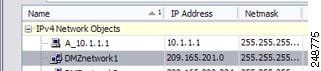
Step 4![]() For the Original Destination Address, click the browse button to add a new network object for DMZ network 1 in the Browse Original Destination Address dialog box.
For the Original Destination Address, click the browse button to add a new network object for DMZ network 1 in the Browse Original Destination Address dialog box.
a.![]() Add the new network object.
Add the new network object.
b.![]() Define the DMZ network 1 addresses, and click OK.
Define the DMZ network 1 addresses, and click OK.

c.![]() Choose the new network object by double-clicking it. Click OK to return to the NAT configuration.
Choose the new network object by double-clicking it. Click OK to return to the NAT configuration.
Step 5![]() Set the NAT Type to Dynamic PAT (Hide) :
Set the NAT Type to Dynamic PAT (Hide) :
Step 6![]() For the Translated Source Address, click the browse button to add a new network object for the PAT address in the Browse Translated Source Address dialog box.
For the Translated Source Address, click the browse button to add a new network object for the PAT address in the Browse Translated Source Address dialog box.
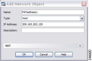
a.![]() Add the new network object.
Add the new network object.
b.![]() Define the PAT address, and click OK.
Define the PAT address, and click OK.
c.![]() Choose the new network object by double-clicking it. Click OK to return to the NAT configuration.
Choose the new network object by double-clicking it. Click OK to return to the NAT configuration.

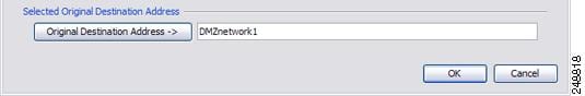
Step 7![]() For the Translated Destination Address, type the name of the Original Destination Address (DMZnetwork1) or click the browse button to choose it.
For the Translated Destination Address, type the name of the Original Destination Address (DMZnetwork1) or click the browse button to choose it.
Because you do not want to translate the destination address, you need to configure identity NAT for it by specifying the same address for the Original and Translated destination addresses.
Step 8![]() Click OK to add the rule to the NAT table.
Click OK to add the rule to the NAT table.
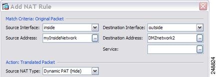
Step 9![]() Add a NAT rule for traffic from the inside network to DMZ network 2:
Add a NAT rule for traffic from the inside network to DMZ network 2:
By default, the NAT rule is added to the end of section 1. If you want to add a NAT rule to section 3, after the network object NAT rules, choose Add NAT Rule After Network Object NAT Rules.
The Add NAT Rule dialog box appears.
Step 10![]() Set the source and destination interfaces:
Set the source and destination interfaces:
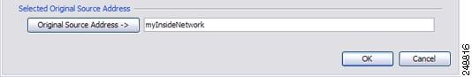
Step 11![]() For the Original Source Address, type the name of the inside network object (myInsideNetwork) or click the browse button to choose it.
For the Original Source Address, type the name of the inside network object (myInsideNetwork) or click the browse button to choose it.
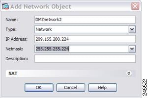
Step 12![]() For the Original Destination Address, click the browse button to add a new network object for DMZ network 2 in the Browse Original Destination Address dialog box.
For the Original Destination Address, click the browse button to add a new network object for DMZ network 2 in the Browse Original Destination Address dialog box.
a.![]() Add the new network object.
Add the new network object.
b.![]() Define the DMZ network 2 addresses, and click OK.
Define the DMZ network 2 addresses, and click OK.
c.![]() Choose the new network object by double-clicking it. Click OK to return to the NAT configuration.
Choose the new network object by double-clicking it. Click OK to return to the NAT configuration.

Step 13![]() Set the NAT Type to Dynamic PAT (Hide) :
Set the NAT Type to Dynamic PAT (Hide) :
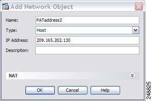
Step 14![]() For the Translated Source Address, click the browse button to add a new network object for the PAT address in the Browse Translated Source Address dialog box.
For the Translated Source Address, click the browse button to add a new network object for the PAT address in the Browse Translated Source Address dialog box.
a.![]() Add the new network object.
Add the new network object.
b.![]() Define the PAT address, and click OK.
Define the PAT address, and click OK.
c.![]() Choose the new network object by double-clicking it. Click OK to return to the NAT configuration.
Choose the new network object by double-clicking it. Click OK to return to the NAT configuration.

Step 15![]() For the Translated Destination Address, type the name of the Original Destination Address (DMZnetwork2) or click the browse button to choose it.
For the Translated Destination Address, type the name of the Original Destination Address (DMZnetwork2) or click the browse button to choose it.
Because you do not want to translate the destination address, you need to configure identity NAT for it by specifying the same address for the Original and Translated destination addresses.

Step 16![]() Click OK to add the rule to the NAT table.
Click OK to add the rule to the NAT table.
Different Translation Depending on the Destination Address and Port (Dynamic PAT)
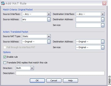
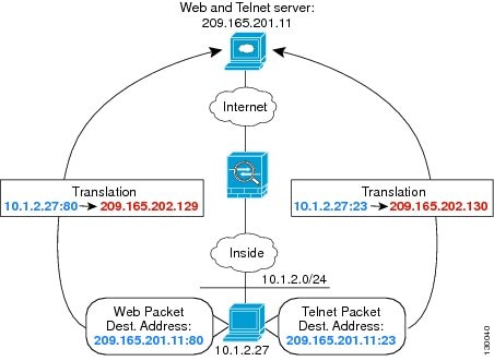
Figure 7-2 shows the use of source and destination ports. The host on the 10.1.2.0/24 network accesses a single host for both web services and Telnet services. When the host accesses the server for Telnet services, the real address is translated to 209.165.202.129: port. When the host accesses the same server for web services, the real address is translated to 209.165.202.130: port.
Figure 7-2 Twice NAT with Different Destination Ports
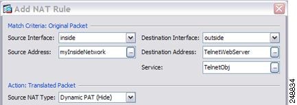
Step 1![]() Add a NAT rule for traffic from the inside network to the Telnet server:
Add a NAT rule for traffic from the inside network to the Telnet server:
By default, the NAT rule is added to the end of section 1. If you want to add a NAT rule to section 3, after the network object NAT rules, choose Add NAT Rule After Network Object NAT Rules.
The Add NAT Rule dialog box appears.
Step 2![]() Set the source and destination interfaces:
Set the source and destination interfaces:
Step 3![]() For the Original Source Address, click the browse button to add a new network object for the inside network in the Browse Original Source Address dialog box.
For the Original Source Address, click the browse button to add a new network object for the inside network in the Browse Original Source Address dialog box.
a.![]() Add the new network object.
Add the new network object.
b.![]() Define the inside network addresses, and click OK.
Define the inside network addresses, and click OK.
c.![]() Choose the new network object by double-clicking it. Click OK to return to the NAT configuration.
Choose the new network object by double-clicking it. Click OK to return to the NAT configuration.
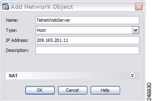
Step 4![]() For the Original Destination Address, click the browse button to add a new network object for the Telnet/Web server in the Browse Original Destination Address dialog box.
For the Original Destination Address, click the browse button to add a new network object for the Telnet/Web server in the Browse Original Destination Address dialog box.
a.![]() Add the new network object.
Add the new network object.
b.![]() Define the server address, and click OK.
Define the server address, and click OK.
c.![]() Choose the new network object by double-clicking it. Click OK to return to the NAT configuration.
Choose the new network object by double-clicking it. Click OK to return to the NAT configuration.

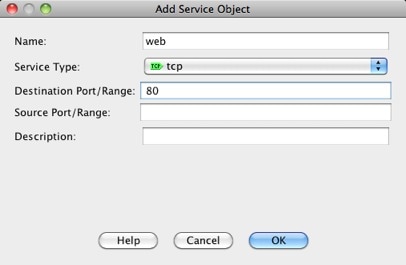
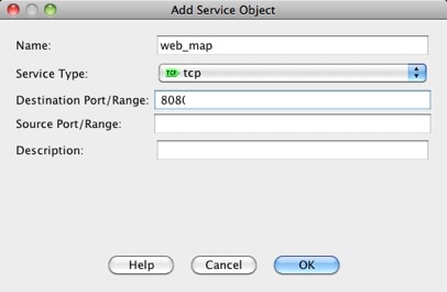
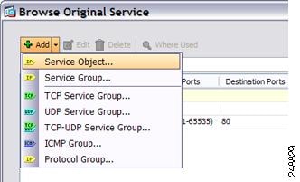
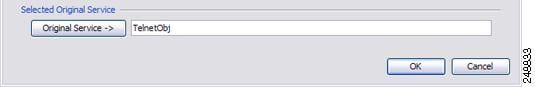
Step 5![]() For the Original Service, click the browse button to add a new service object for Telnet in the Browse Original Service dialog box.
For the Original Service, click the browse button to add a new service object for Telnet in the Browse Original Service dialog box.
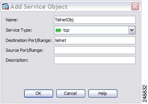
a.![]() Add the new service object.
Add the new service object.
b.![]() Define the protocol and port, and click OK.
Define the protocol and port, and click OK.
c.![]() Choose the new service object by double-clicking it. Click OK to return to the NAT configuration.
Choose the new service object by double-clicking it. Click OK to return to the NAT configuration.
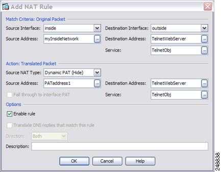
Step 6![]() Set the NAT Type to Dynamic PAT (Hide) :
Set the NAT Type to Dynamic PAT (Hide) :
Step 7![]() For the Translated Source Address, click the browse button to add a new network object for the PAT address in the Browse Translated Source Address dialog box.
For the Translated Source Address, click the browse button to add a new network object for the PAT address in the Browse Translated Source Address dialog box.
a.![]() Add the new network object.
Add the new network object.
b.![]() Define the PAT address, and click OK.
Define the PAT address, and click OK.
c.![]() Choose the new network object by double-clicking it. Click OK to return to the NAT configuration.
Choose the new network object by double-clicking it. Click OK to return to the NAT configuration.
Step 8![]() For the Translated Destination Address, type the name of the Original Destination Address (TelnetWebServer) or click the browse button to choose it.
For the Translated Destination Address, type the name of the Original Destination Address (TelnetWebServer) or click the browse button to choose it.
Because you do not want to translate the destination address, you need to configure identity NAT for it by specifying the same address for the Original and Translated destination addresses.
Step 9![]() Click OK to add the rule to the NAT table.
Click OK to add the rule to the NAT table.
Step 10![]() Add a NAT rule for traffic from the inside network to the web server:
Add a NAT rule for traffic from the inside network to the web server:
By default, the NAT rule is added to the end of section 1. If you want to add a NAT rule to section 3, after the network object NAT rules, choose Add NAT Rule After Network Object NAT Rules.
The Add NAT Rule dialog box appears.
Step 11![]() Set the real and mapped interfaces:
Set the real and mapped interfaces:
Step 12![]() For the Original Source Address, type the name of the inside network object (myInsideNetwork) or click the browse button to choose it.
For the Original Source Address, type the name of the inside network object (myInsideNetwork) or click the browse button to choose it.
Step 13![]() For the Original Destination Address, type the name of the Telnet/web server network object (TelnetWebServer) or click the browse button to choose it.
For the Original Destination Address, type the name of the Telnet/web server network object (TelnetWebServer) or click the browse button to choose it.
Step 14![]() For the Original Service, click the browse button to add a new service object for HTTP in the Browse Original Service dialog box.
For the Original Service, click the browse button to add a new service object for HTTP in the Browse Original Service dialog box.
a.![]() Add the new service object.
Add the new service object.
b.![]() Define the protocol and port, and click OK.
Define the protocol and port, and click OK.

c.![]() Choose the new service object by double-clicking it. Click OK to return to the NAT configuration.
Choose the new service object by double-clicking it. Click OK to return to the NAT configuration.
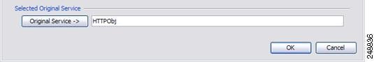
Step 15![]() Set the NAT Type to Dynamic PAT (Hide) :
Set the NAT Type to Dynamic PAT (Hide) :
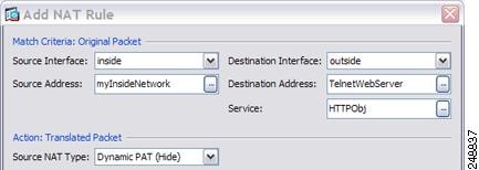
Step 16![]() For the Translated Source Address, click the browse button to add a new network object for the PAT address in the Browse Translated Source Address dialog box.
For the Translated Source Address, click the browse button to add a new network object for the PAT address in the Browse Translated Source Address dialog box.
a.![]() Add the new network object.
Add the new network object.
b.![]() Define the PAT address, and click OK.
Define the PAT address, and click OK.
c.![]() Choose the new network object by double-clicking it. Click OK to return to the NAT configuration.
Choose the new network object by double-clicking it. Click OK to return to the NAT configuration.
Step 17![]() For the Translated Destination Address, type the name of the Original Destination Address (TelnetWebServer) or click the browse button to choose it.
For the Translated Destination Address, type the name of the Original Destination Address (TelnetWebServer) or click the browse button to choose it.
Because you do not want to translate the destination address, you need to configure identity NAT for it by specifying the same address for the Original and Translated destination addresses.
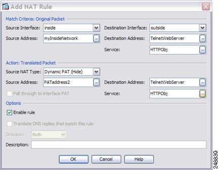
Step 18![]() Click OK to add the rule to the NAT table.
Click OK to add the rule to the NAT table.
Feature History for Twice NAT
Table 7-1 lists each feature change and the platform release in which it was implemented. ASDM is backwards-compatible with multiple platform releases, so the specific ASDM release in which support was added is not listed.
 Feedback