- Preface
-
- Configure Authentication
- Configure the NCS4K-2H-W Card
- Configure LC Priority Shutdown
- Configure AINS
- Configure Line Cards Using CTC
- Configure Circuits
- Configure the Bridge and Roll
- Configure Performance Monitoring
- Smart Licensing
- Manage Alarm Profiles
- Configure High Availability
- Configuring PRBS
- Configuring Breakout
- Manage the Node
- Configure SNMP
- Upgrade a Fabric Card
- Cable Management Utility
- Configure Affinity for OTN using CTC
- Migration : NCS4K-ECU to NCS4K-ECU2
- 24 Low Rate (LR) Datapath
- Configure Link Layer Discovery Protocol Using CTC
-
- Configure Authentication
- Configure Access Control Lists
- Configure LC Priority Shutdown
- Configure Controllers
- Configure the OTN Circuits
- Configure the OTN Protection
- Configure SNMP
- Configure Performance Monitoring
- Configure Fault Management
- Configuring PRBS
- Configuring Breakout
- Configure High Availability1
- Configure Layer 3 VPNs
- Configure Flex LSP
- Configure ISIS
- Bidirectional Forwarding Detection
- OSPF-IPv4
- Configure Ethernet OAM
- Configure Ethernet Service Activation Test
- Ethernet Local Management Interface
- MPLS Traffic Engineering
- Configure Frequency Synchronization
- Configuring Point to Point Layer 2 Services
- VLAN over ODU
- BGP Route Reflect
- Configure Smart Licensing
- Configure Link Aggregation
- Configure Link Layer Discovery Protocol
- Configure Affinity for OTN
- System Upgrade
- Capture Logs
- Inter-Rack RP Pairing
- Inter-rack Timing
- Configure Ethernet Data Plane Loopback
- Configure Zero Touch Provisioning
- Implement LPTS
- System Messages
- Administrative and Service States
- Understand OTN Circuits
- Understand Circuit Diversity
- Understand OSPF
- Understand MPLS TE
- Understand Tandem Connection Monitoring
- Understand ISSU Upgrade
- Understand GCC Management
- Understand GMPLS
- Understand Explicit Path
- NTP-K2 Pre-requisite for OTN Circuits Using CTC
- DLP-K61 Provision Management IP Address
- DLP-K9 Configure the Loopback on an Interface Using CTC
- DLP-K10 Add OSPF on an Interface Using CTC
- DLP-K11 Configure the OSPF-TE on an Interface Using CTC
- DLP-K12 Configure an MPLS-TE Instance Using CTC
- DLP-K13 Configure the Refresh Optical Interval on OTN Controllers Using CTC
- NTP-K3 Configure OTN Circuits Using CTC
- DLP-K14 Add a Path Protection Profile Using CTC
- DLP-K62 Provision Loopback Interface
- DLP-K15 Load a Path Protection Profile Using CTC
- DLP-K16 Store a Path Protection Profile Using CTC
- DLP-K17 Configure an OTN Circuit Using CTC
- DLP-K60 Configure an Open End OTN Circuit Using CTC
- DLP-K18 Discover a Circuit Using CTC
- DLP-K19 Edit General Parameters of a Circuit Using CTC
- DLP-K20 Edit ODU Configuration of a Circuit Using CTC
- DLP-K22 Add an Explicit Path Using CTC
- DLP-K23 Store an Explicit Path Using CTC
- DLP-K24 Load an Explicit Path Using CTC
- DLP-K27 Create an LMP Using CTC
- DLP-K90 Configuring OTN Circuits Using Node Configuration Wizard
- GMPLS Optical Channel Trail
- DLP-G54 Create a Local User on a Single Node Using CTC
- DLP-G501 Creating Notification Filters
- DLP-G124 Apply Alarm Profiles to Cards and Nodes
- DLP-G123 Apply Alarm Profiles to Ports
- DLP-G55 Creating a New User on Multiple Nodes
- Setting Maximum Password Length Using CTC
- NTP-G22 Verifying Common Card Installation
Configure
Circuits
The OTN circuits allow you to setup end to end circuits from the origin to a destination network element. The Optical Channel Trail circuits allow you to create circuits in a network where the NCS 4000 series node is connected to a ONS 15454, ONS 15454 M2, or ONS 15454 M6 nodes. This chapter provides the CTC procedures to configure the circuits.
- Understand OTN Circuits
- Understand Circuit Diversity
- Understand OSPF
- Understand MPLS TE
- Understand Tandem Connection Monitoring
- Understand ISSU Upgrade
- Understand GCC Management
- Understand GMPLS
- Understand Explicit Path
- NTP-K2 Pre-requisite for OTN Circuits Using CTC
- NTP-K3 Configure OTN Circuits Using CTC
- DLP-K90 Configuring OTN Circuits Using Node Configuration Wizard
- GMPLS Optical Channel Trail
- DLP-G54 Create a Local User on a Single Node Using CTC
- DLP-G501 Creating Notification Filters
- DLP-G124 Apply Alarm Profiles to Cards and Nodes
- DLP-G123 Apply Alarm Profiles to Ports
- DLP-G55 Creating a New User on Multiple Nodes
- Setting Maximum Password Length Using CTC
- NTP-G22 Verifying Common Card Installation
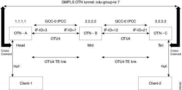
Understand OTN Circuits
An OTN circuit provides the ability to aggregate different types of traffic such as Ethernet, SONET or SDH, and packet over OTN at different data rates such as 1.25, 2.5, 10, or 100 GBit per second. This aggregated traffic is transported by network elements that acts as OTN cross connections.
Understand Circuit Diversity
This feature enables the user to create a circuit diverse of another circuit. A diverse circuit is a circuit that takes a path based on certain diversity conditions.
When request for creating a diverse circuit is received the system first tries to find a SRLG diverse path. If SRLG diverse path is not available then it falls to Node and Link diversity and if this also fails then basic Link diverse path is used. It is also possible to enable diversity on an existing circuit but this will trigger re-signaling of the circuit.
Following are the restrictions applicable to this feature (not applicable for UNI circuits) :
-
The diverse circuit has the same head node.
-
The feature is supported only for 1+0 circuits.
-
Strict diversity is supported i.e. if a diverse path is not found, the circuit is not created.
Understand OSPF
Open Shortest Path First (OSPF) is a routing protocol designed to run an autonomous system. It maintains an identical database describing the topology of an autonomous system. From the identical database, a shortest path-tree calculates the routing table. OSPF-TE allows controlling the data packet's path.
OSPF provides following features:
Understand MPLS TE
MPLS TE learns the topology and resources available in a network and then maps traffic flows to respective paths based on resource requirements and network resources, for example, bandwidth. MPLS TE builds a unidirectional tunnel from a source to a destination in the form of a label switched path (LSP), which is then used to forward traffic. Tunnel head end or tunnel source is the point where the tunnel begins, the tunnel tail end or tunnel destination is the node where the tunnel ends .
Understand Tandem Connection Monitoring
Tandem Connection Monitoring (TCM) layer is used for protection applications, for example, APS. In traditional SONET/SDH applications, the path layer is used for this purpose, however, it can be influenced by errors that occur outside a given operators network and cause undesired protection switch events to occur within their network. Since TCM can isolate a service to a given domain, it can be used to trigger protection applications and avoid such issues.
Understand ISSU Upgrade
In-Service Software Upgrade (ISSU) is a technique that updates the software packages on a network element without affecting the traffic. By using ISSU, you can deploy new Cisco IOS XR Software images that supports new software features and services. The Cisco IOS XR ISSU capability extends Cisco high availability innovations for minimizing planned downtime for service provider networks.
Understand GCC Management
General Communication Channel (GCC) is an in-band side channel that carries transmission management and signaling information within optical transport network elements.
There are two types of GCC links:
Understand GMPLS
Generalized Multi-Protocol Label Switching (GMPLS) extends the packet based MPLS protocol to allow creation and maintenance of tunnels across the networks that consist of non-packet switching devices. GMPLS tunnels can traverse the Time-Division Multiplex (TDM) interface and switching types.
The following protocols are associated with GMPLS:
Understand Explicit Path
Explicit path refers to a user defined path taken by a circuit. GMPLS dynamically determines the path to be taken by a circuit but user can override this path by configuring an explicit path.
NTP-K2 Pre-requisite for OTN Circuits Using CTC
| Purpose |
This procedure configures the pre-requisite procedures of OTN circuit. |
| Tools/Equipment | None |
| Prerequisite Procedures | None |
| Required/As Needed | As needed |
| Onsite/Remote | Onsite or remote |
| Security Level | Provisioning or higher |
Perform any of the following procedures as needed to configure the OTN circuit:
End of procedure. |
DLP-K61 Provision Management IP Address
|
This procedure provisions the management IP address for the node. |
|
DLP-K9 Configure the Loopback on an Interface Using CTC
| This procedure provides instructions to configure the loopback on an interface using CTC. It also helps in management logging and authentication of a user on an interface. | |
| None | |
| Login to CTC in System Setup and Software Installation Guide for Cisco NCS 4000 Series | |
| As needed | |
| Onsite or remote | |
| Provisioning or higher |
| Step 1 | In the Node View, double-click the line card (NCS4K-20T-O-S/ NCS4K-2H-O-K/ NCS4K-2H-W/NCS4K-24LR-O-S). |
| Step 2 | Click the Maintenance > Loopback tab. |
| Step 3 | To configure
loopback on OTN controllers, perform the following steps in the screen that
appears:
|
| Step 4 | Return to your originating procedure (NTP). |
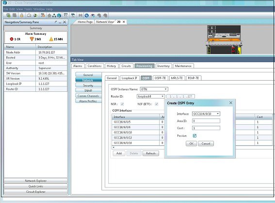
DLP-K10 Add OSPF on an Interface Using CTC
| The Adding OSPF allows to setup link between two different router and maintain the connectivity interface. This procedure provides instructions to configure the OSPF on an interface using CTC. | |
| None | |
| Login to CTC in System Setup and Software Installation Guide for Cisco NCS 4000 Series | |
| As needed | |
| Onsite or remote | |
| Provisioning or higher |
DLP-K11 Configure the OSPF-TE on an Interface Using CTC
| OSPF-TE allows controlling the path of data packets. This procedure provides instructions to configure the OSPF-TE using CTC. | |
| None | |
| Login to CTC in System Setup and Software Installation Guide for Cisco NCS 4000 Series | |
| As needed | |
| Onsite or remote | |
| Provisioning or higher |
DLP-K12 Configure an MPLS-TE Instance Using CTC
| Traffic engineering enables route network traffic to offer the best service to the users and reduces the cost of the network. This procedure provides instructions to configure an MPLS-TE instance that helps to route network traffic using CTC. | |
| None | |
| Login to CTC in System Setup and Software Installation Guide for Cisco NCS 4000 Series | |
| As needed | |
| Onsite or remote | |
| Provisioning or higher |
DLP-K13 Configure the Refresh Optical Interval on OTN Controllers Using CTC
| Refresh Optical Interval allows displays the time that system takes to automatically refresh the controllers. Refresh Optical Missed displays the number of refresh optical missed messages. This procedure provides the instructions to configure the refresh optical interval on OTN controllers using CTC. | |
| None | |
| Login to CTC in System Setup and Software Installation Guide for Cisco NCS 4000 Series | |
| As needed | |
| Onsite or remote | |
| Provisioning or higher |
NTP-K3 Configure OTN Circuits Using CTC
| Purpose |
This procedure configures an OTN circuit Using CTC. |
| Tools/Equipment | None |
| Prerequisite Procedures | DLP-K1 Configure an OTN Controller Using CTC |
| Required/As Needed | As needed |
| Onsite/Remote | Onsite or remote |
| Security Level | Provisioning or higher |
| Step 1 | Perform any of the following procedures as needed to create, load, and store the path protection profile: |
| Step 2 | Perform any of the following procedures as needed to configure an OTN circuit: |
| Step 3 | Perform any of
the following procedures as needed to create, load, and store the explicit
path:
End of procedure. |
DLP-K14 Add a Path Protection Profile Using CTC
| This procedure provides instructions to add a path protection profile using CTC. | |
| None | |
| Login to CTC in System Setup and Software Installation Guide for Cisco NCS 4000 Series | |
| As needed | |
| Onsite or remote | |
| Provisioning or higher |
DLP-K62 Provision Loopback Interface
|
This procedure provisions the loopback interface on the node. |
|
DLP-K15 Load a Path Protection Profile Using CTC
| This procedure provides instructions to load a path protection profile using CTC. | |
| None | |
| Login to CTC in System Setup and Software Installation Guide for Cisco NCS 4000 Series | |
| As needed | |
| Onsite or remote | |
| Provisioning, higher or retriever |
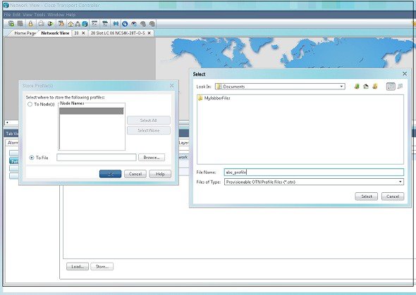
DLP-K16 Store a Path Protection Profile Using CTC
| Storing a Path Protection Profile allows to store cross connection on the same chassis. This procedure provides instructions to store a path protection profile using CTC. | |
| None | |
|
|
| As needed | |
| Onsite or remote | |
| Provisioning or higher |
DLP-K17 Configure an OTN Circuit Using CTC
| OTN circuit allows the end user to set up an open end circuit from an origin to a destination Network Element. This procedure provides instructions to configure an OTN circuit using CTC. | |
| None | |
| You can load the profiles from a file that has OTN extension. | |
| As needed | |
| Onsite or remote | |
| Provisioning or higher |
| Step 1 | In the Network View, click the OTN > Circuits tab. |
| Step 2 | Click Create. The Circuit Creation wizard appears. |
| Step 3 | In the Circuit Type screen of the wizard, choose a circuit type ODU TUNNEL from the list. |
| Step 4 | Click Next. |
| Step 5 | In the Circuit
Attributes screen of the wizard:
|
| Step 6 | Return to your originating procedure (NTP). |
DLP-K60 Configure an Open End OTN Circuit Using CTC
| OTN circuit allows the end user to setup end to end circuits from an origin to a destination Network Element. This procedure provides instructions to configure an open end OTN circuit using CTC. | |
| None | |
| Login to CTC in System Setup and Software Installation Guide for Cisco NCS 4000 Series | |
| As needed | |
| Onsite or remote | |
| Provisioning or higher |
| Step 1 | In the Network View, click the OTN > Circuits tab. |
| Step 2 | Click Create. The Circuit Creation wizard appears. |
| Step 3 | In the Circuit Type screen of the wizard, choose a circuit type ODU UNI from the list. |
| Step 4 | Enter a value between 1 to 80 for the number of circuits to be created. |
| Step 5 | Click Next. |
| Step 6 | In the Circuit
Attributes screen of the wizard:
|
| Step 7 | Return to your originating procedure (NTP). |
DLP-K18 Discover a Circuit Using CTC
| This procedure provides instructions to discover a circuits from the list of OTN circuits using CTC. | |
| None | |
| Login to CTC in System Setup and Software Installation Guide for Cisco NCS 4000 Series | |
| As needed | |
| Onsite or remote | |
| Provisioning or higher |
DLP-K19 Edit General Parameters of a Circuit Using CTC
| This procedure provides instructions to edit general parameters of an OTN circuit using CTC. | |
| None | |
| Login to CTC in System Setup and Software Installation Guide for Cisco NCS 4000 Series | |
| As needed | |
| Onsite or remote | |
| Provisioning or higher |
DLP-K20 Edit ODU Configuration of a Circuit Using CTC
| This procedure helps to edit the ODU configuration of a circuit. | |
| None | |
| Login to CTC in System Setup and Software Installation Guide for Cisco NCS 4000 Series | |
| As needed | |
| Onsite or remote | |
| Provisioning or higher |
| Step 1 | In the Network View, click the OTN > Circuits tab. | ||
| Step 2 | Select a circuit from the list. | ||
| Step 3 | Click Edit. | ||
| Step 4 | Click ODU Configuration tab. | ||
| Step 5 | From the left
pane, click the
ODU Line
Configuration tab. Perform the following steps in the Edit ODU Line
Configuration screen that appears:
| ||
| Step 6 | From the left
pane, click the
ODU TTI
Configuration tab. Perform the following steps in the Edit ODU TTI
Configuration screen that appears:
| ||
| Step 7 | From the left pane, click the TCM Line Configuration tab. Perform the following steps in the Edit TCM Line Configuration screen that appears: | ||
| Step 8 | From the left
pane, click the
TCM
TTI Configuration tab. Perform the following steps in the Edit TCM
TTI Configuration screen:
| ||
| Step 9 | From the left
pane, click the
PM
Thresholds tab.
| ||
| Step 10 | Return to your originating procedure (NTP). |
DLP-K22 Add an Explicit Path Using CTC
| This procedure provides instructions to create an explicit path using CTC. | |
| None | |
|
Login to CTC in System Setup and Software Installation Guide for Cisco NCS 4000 Series. |
|
| As needed | |
| Onsite or remote | |
| Provisioning or higher |
DLP-K23 Store an Explicit Path Using CTC
| This procedure provides instructions to store an explicit path using CTC. | |
| None | |
|
Login to CTC in System Setup and Software Installation Guide for Cisco NCS 4000 Series. |
|
| As needed | |
| Onsite or remote | |
| Provisioning or higher |
DLP-K24 Load an Explicit Path Using CTC
| This procedure provides instructions to load an explicit path using CTC. | |
| None | |
|
Login to CTC in System Setup and Software Installation Guide for Cisco NCS 4000 Series. |
|
| As needed | |
| Onsite or remote | |
| Provisioning or higher |
DLP-K27 Create an LMP Using CTC
| Purpose | Link Management Protocol (LMP) is used to manage Traffic Engineering (TE) link. It allows multiple data link into a single Traffic Engineering (TE) link that runs between a pair of node. This procedure provides instructions to create an LMP using CTC. |
| Tools/Equipment | None |
| Prerequisite Procedures |
Login to CTC in System Setup and Software Installation Guide for Cisco NCS 4000 Series. |
| Required/As Needed | As needed |
| Onsite/Remote | Onsite or remote |
| Security Level | Provisioning or higher |
| Step 1 | In the Network View, click the Provisioning > LMP tab. | ||
| Step 2 | Click
Create.
| ||
| Step 3 | Click
Next. Perform the following steps in the LMP
Termination screen that appears in the LMP creation wizard
| ||
| Step 4 | Click
Next. Perform the following steps in the Optical
Parameters screen that appears in the LMP creation wizard:
| ||
| Step 5 | Click
Next. Perform the following steps in the Alien
Wavelength screen that appears in the LMP creation wizard:
| ||
| Step 6 | Click Finish to create the LMP. | ||
| Step 7 | Return to your originating procedure (NTP). |
DLP-K90 Configuring OTN Circuits Using Node Configuration Wizard
| Purpose |
This procedure configures the OTN circuits using Node Configuration Wizard. |
| Tools/Equipment | None |
| Prerequisite Procedures | |
| Required/As Needed | As needed |
| Onsite/Remote | Onsite or remote |
| Security Level | Provisioning or higher |
| Step 1 | In the Node View or Card View, right-click anywhere and choose the |
| Step 2 | In the
IP
Configuration pane, if you want to provision the Virtual IP, Management IP,
EMS IP, Craft IP, Gateway IP and the corresponding mask, complete the following
:
|
| Step 3 | Click the Next button to save the changes and open the OTN Topology pane. |
| Step 4 | Click Close to save the changes and close the Node Configuration Wizard. |
| Step 5 | In the loopback interface area, Complete the following : You cannot delete the Loopback information once configured. |
| Step 6 | If you want to
create the controller, configure GCC interface, MPLS-TE, RSVP-TE on a
particular card, complete the following :
|
| Step 7 | If you want to
delete the controller, perform the following:
|
| Step 8 | In the
OSPF area,
Complete the following :
|
| Step 9 | Click Previous to save the current changes and display the previous configuration pane. |
| Step 10 | Click Close to save the changes and close the Node Configuration Wizard. |
| Step 11 | Return to your originating procedure (NTP). |
GMPLS Optical Channel Trail
The user can create a GMPLS optical channel trail (OCH Trail) in a network where the NCS 4000 series node is connected to a ONS 15454, ONS 15454 M2, or ONS 15454 M6 nodes. The OCH trail circuit originates from a NCS4k-2H-W interface on the source NCS 4000 node and terminates on the NCS4k-2H-W interface on the destination NCS 4000 node to create an optical connection. The prerequisite for the OCH trail circuit is to create a Link Management Protocol (LMP) link between the NCS4k-2H-W interface on the NCS 4000 node and the optical channel Add/Drop interface on the ONS 15454, ONS 15454 M2, or ONS 15454 M6 nodes.
The OCH Trail circuit is used to transmit traffic over a long distance. The traffic transmitted by the OCH Trail circuit is used as a OTU link by the OTN layer to route the OTN circuit.
- DLP-G708 Create a GMPLS Optical Channel Trail
- GMPLS Path Constraints
- DLP-G710 Re-route Wavelength of GMPLS Circuits
DLP-G708 Create a GMPLS Optical Channel Trail
|
This task creates a GMPLS OCH trail circuit between NCS4K-2H-W and NCS4K-2H10T-OP-KS cards when provisioned in L2-over-NCS4k-2H-W mode. For OCH trails connecting NCS4K-2H-W and NCS4K-2H10T-OP-KS cards in L2-over-NCS4k-2H-W mode, the OCH trail provides the links associated to the SVLAN entities. In Release 10.0.1, as regards OCH trails connecting CRS routers, the OCH trail provides end-to-end circuit connectivity between the CRS routers passing through an MSTP network. This task creates a GMPLS OCH trail circuit between NCS 4000 series nodes that are connected to the ONS 15454 nodes. |
|
|
None |
|
 Note | OCH trail circuits are created automatically when you provision OCHCC circuits between TXP and MXP cards or TXP or MXP cards and router PLIM interfaces (10G ethernet controllers). |
Note | When the user creates a GMPLS OCH Trail circuit on the VTXP port, it is possible to retune the wavelength under these conditions:
|
| Step 1 | From the View menu, choose Go to Network View and click the Network Functional View icon in the toolbar. The Circuit Maintenance View opens. | ||||||||||||
| Step 2 | From the Change Perspective drop-down list in the toolbar, choose Circuit Creation. The Circuit Creation view opens. | ||||||||||||
| Step 3 | In the Circuit Parameters
pane, provision the OCH Trail circuit attributes:
| ||||||||||||
| Step 4 | In the
GMPLS/WSON Optional Configuration pane, specify the attributes:
| ||||||||||||
| Step 5 | In the GMPLS/WSON Wavelength Parameters pane, choose a wavelength from the field. | ||||||||||||
| Step 6 | Configure the restoration
parameters for the OCH trail circuit in the GMPLS/WSON Restoration
Configuration pane.
For more information about
configuring the restoration parameters, see the "GMPLS Restoration
Configuration" section in "Node Reference" chapter.
| ||||||||||||
| Step 7 | Configure the source and destination ports at the circuit endpoints in the map. For more information about configuring the source and destination ports, see the "Source and Destination Port Configuration” section in "Node Reference" chapter.. Right-click the node in the map and select the source and destination ports from the drop-down list. | ||||||||||||
| Step 8 | Define the working or protect port parameters. For more information, see the "Working and Protect Port Parameters” section in "Node Reference" chapter. Click Apply in the Working Port Parameters pane and Protected Port Parameters pane, to apply the settings. | ||||||||||||
| Step 9 | Click Apply in the Circuit Parameters pane. | ||||||||||||
| Step 10 | Click Yes in the Create Circuits confirmation dialog box. The OCH trail appear in the Circuits tab in the Network Data pane. After the circuit status has been verified, the DISCOVERED status appears in the Status column. Depending on the size of the network, the circuit might take a few minutes to come up. | ||||||||||||
| Step 11 | Return to your originating procedure (NTP). |
GMPLS Path Constraints
During GMPLS circuit creation or wavelength rerouting, it is possible to force specific nodes and links to be included or excluded in the circuit path by applying specific constraints. The GMPLS circuit is created if a feasible path is found that complies with the specified constraints. You can also modify the constraints of an existing circuit in the circuit maintenance view. The circuit constraints are displayed as icons on the circuit map in the graphical view. The icons also contain an ordinal number that indicates the order in which the constraint will be applied to the link or node.
In the NCS4k-2H-W network functional view, the W&P Constraints Config drop-down list in the toolbar provides the constraint options listed in the following table . Choose the required option and select the node or span in the graphical view to which the constraint must be applied.
|
The working and protected path do not pass through the selected node. |
|
|
The working and protected path do not use the selected span. |
|
In the Wavelength re-routing view, the Constraints Config drop-down list provides constraint options listed in the following table. Choose the required option and select the node or span in the graphical view to which the constraint must be applied.
Note | The constraint options can also be accessed by right-clicking the node or span. |
DLP-G710 Re-route Wavelength of GMPLS Circuits
|
This task reroutes an existing GMPLS circuit through an alternate path based on the specified path constraints. |
|
Note | GMPLS OCHCC circuits cannot be rerouted. Only the OCH Trail associated with the OCHCC circuit can be rerouted. |
| Step 1 | From the View menu, choose Go to Network View and click the FV icon in the toolbar. The NFV view opens. | ||
| Step 2 | From the Change Perspective drop-down list in the toolbar, choose GMPLS. The GMPLS view opens. | ||
| Step 3 | Click the Wavelength re-routing button. | ||
| Step 4 | In the confirmation dialog box, click Yes to enter the wavelength re-routing view. The Wavelength re-routing pane is displayed. | ||
| Step 5 | In the Circuits tab, select the GMPLS circuit to be rerouted. | ||
| Step 6 | From the Constraint Config drop-down list, select the required constraint type. For more information about the various constraint types, see the Reroute Path Constraint Options table. | ||
| Step 7 | In the map, select the node or link to which the constraint is to be applied. | ||
| Step 8 | Repeat
Step 5 and
Step 6 to apply more
constraints, as needed.
| ||
| Step 9 | Click Apply. The circuit is rerouted if a feasible path is found that complies with the specified constraints. After a successful reroute, a confirmation message is displayed. Otherwise, a failure notification is displayed. | ||
| Step 10 | Repeat the reroute process in case the reroute fails inStep 9. ClickClear in the Wavelength re-routing pane to clear the previous selections. Repeat the Step 6 through Step 9. | ||
| Step 11 | Click the Wavelength re-routing button on the toolbar to close the Wavelength re-routing pane. In the confirmation dialog box, click Yes. | ||
| Step 12 | Return to your originating procedure (NTP). |
DLP-G54 Create a Local User on a Single Node Using CTC
| Step 1 | In node view or network view, click the tabs. | ||
| Step 2 | In the Users window, click Create. | ||
| Step 3 | In the Create User dialog
box, enter the following:
| ||
| Step 4 | Click OK. | ||
| Step 5 | Return to your originating procedure (NTP). |
DLP-G501 Creating Notification Filters
| Step 1 | In node view, click the tabs. |
| Step 2 | Click Create. |
| Step 3 | In the Create Notify dialog box, enter the following information:
|
| Step 4 | Click OK to save the information. |
| Step 5 | Return to your originating procedure (NTP). |
DLP-G124 Apply Alarm Profiles to Cards and Nodes
|
Purpose |
This task applies a custom or default alarm profile to cards or nodes. |
|
Tools/Equipment |
None |
|
Prerequisite Procedures |
|
|
Required/As Needed |
As needed |
|
Onsite/Remote |
Onsite or remote |
|
Security Level |
Provisioning or higher |
Note | Alarm severity does not change for AR_MXP, AR_XP, and AR_XPE cards under the following conditions:
|
DLP-G123 Apply Alarm Profiles to Ports
|
Purpose |
This task applies a custom or default alarm severity profile to a port or ports. |
|
Tools/Equipment |
None |
|
Prerequisite Procedures |
|
|
Required/As Needed |
As needed |
|
Onsite/Remote |
Onsite or remote |
|
Security Level |
Provisioning or higher |
Note | You can also apply alarm profiles to cards using the DLP-G124 Apply Alarm Profiles to Cards and Nodes. |
| Step 1 | In node view
(single-shelf mode) or shelf view (multishelf mode), double-click the card that
you want to change to open the card view.
| ||
| Step 2 | Click the
Provisioning > Alarm Profiles > Alarm Behavior
tabs.
Go to next step to apply profiles to a port. Go to DLP-G123 Apply Alarm Profiles to Ports to apply profiles to all ports on a card. | ||
| Step 3 | To apply profiles on a port basis: | ||
| Step 4 | To apply
profiles to all ports on a card:
| ||
| Step 5 | To reapply a previous alarm profile after you have applied a new one, select the previous profile and click Apply again. | ||
| Step 6 | Return to your originating procedure (NTP). |
DLP-G55 Creating a New User on Multiple Nodes
|
This task adds a new user to multiple ONS 15454NCS 2000 nodes managed by CTC. |
|
Note | All nodes where you want to add users must be accessible in network view. |
| Step 1 | From the View menu, choose Go to Network View. | ||
| Step 2 | Click the tabs. | ||
| Step 3 | In the Users window, click Create. | ||
| Step 4 | In the Create User dialog
box, enter the following:
| ||
| Step 5 | In the Select Applicable Nodes area, deselect any nodes where you do not want to add the user (all network nodes are selected by default). | ||
| Step 6 | Click OK. | ||
| Step 7 | In the User Creation Results dialog box, verify that the user was added to all the nodes chosen in Step 5. If not, click OK and repeat Steps 2 through 6. If the user was added to all nodes, click OK and continue with the next step. | ||
| Step 8 | Return to your originating procedure (NTP). |
Setting Maximum Password Length Using CTC
|
This task sets the maximum password length for a local user. |
|
| Step 1 | In node view, click the tabs. | ||
| Step 2 | In the
Password Complexity area, click
Maximum Length drop-down
list and choose the desired maximum length for password.
| ||
| Step 3 | Click Apply. | ||
| Step 4 | Return to your originating procedure (NTP). |
NTP-G22 Verifying Common Card Installation
|
This procedure verifies the following:
It also verifies the installation of the AIC-I and MS-ISC-100T cards, if they are installed. |
|
|
Chapter 1, “Install the Cisco ONS 15454, ONS 15454 M2, and ONS 15454 M6 Shelf” in the Cisco ONS 15454 Hardware Installation Guide Cisco NCS 2000 Series Hardware Installation Guide |
|
| Step 1 | Verify the following:
| ||
| Step 2 | Verify that the FAIL LED is off on both the control cards. | ||
| Step 3 | Verify that the
green ACT (active) LED is illuminated on one control card and that the amber
STBY (standby) LED is illuminated on the other control card.
| ||
| Step 4 | (On 15454-DWDM
shelf) If the AIC-I card is installed, verify that it is installed in Slot 9
and that its ACT (active) LED displays a solid green light.
| ||
| Step 5 | Verify that the software release shown on the LCD
matches the software release required for your network. On the LCD, the
software release is shown under the platform (SONET or SDH) and
date/temperature. If the release does not match, perform one of the following
procedures:
Stop. You have completed this procedure. | ||
| Step 6 | (On ONS 15454 shelf) If the node will be configured
as a multishelf node, verify that redundant MS-ISC-100T cards are installed
(Slots 6 and 12 are recommended) and that the green ACT (active) LED is
illuminated on both cards.
Stop. You have completed this procedure. |
 Feedback