Cisco IR500 Series WPAN Gateway and WPAN Range Extender Installation and Configuration Guide
Bias-Free Language
The documentation set for this product strives to use bias-free language. For the purposes of this documentation set, bias-free is defined as language that does not imply discrimination based on age, disability, gender, racial identity, ethnic identity, sexual orientation, socioeconomic status, and intersectionality. Exceptions may be present in the documentation due to language that is hardcoded in the user interfaces of the product software, language used based on RFP documentation, or language that is used by a referenced third-party product. Learn more about how Cisco is using Inclusive Language.
- Updated:
- November 19, 2014
Chapter: Overview
Overview
This chapter describes the Cisco Industrial Routers (IR500) Series WPAN Gateway and WPAN Range Extender and includes the following topics:
Features
WPAN Gateway Features
The WPAN gateway provides secure network connectivity over 6LoWPAN/RPL/IEEE 802.15.4g/e subnets to field devices equipped with Ethernet and serial adapters. The device features:
–![]() 1 x IEEE 802.15.4g/e WPAN 902-928 MHz Mesh interface
1 x IEEE 802.15.4g/e WPAN 902-928 MHz Mesh interface
- Alarm input
- 6LoWPAN (RFC4944 and RFC6282)—IPv6 adaptation layer
- RPL (RFC 6206, 6550, 6551, 6553, 6554, 6719)—Layer-3 Mesh Networking
- IEEE 802.1x and 802.11i—Authentication and Key Management
- Constrained Application Protocol (CoAP) and CoAP Simple Management Protocol (CSMP) network management
- Raw Socket TCP—non-IP serial devices connectivity
- Real-Time Clock—for maintaining the current time
- Temperature Sensor—for measuring internal temperature of the device
- IP30 enclosure
WPAN Range Extender Features
The WPAN range extender extends the range of an RF wireless mesh network, providing longer reach between WPAN endpoints and other WPAN networks.
WPAN range extenders support the full CG-Mesh network platform, including IEEE 802.15.4g/e, IEEE 802.1X, IPv6, and RPL.
The WPAN range extender features:
- Small form factor IEEE 802.15.4g/e 902-928 MHz frequency band operation
- 1 x Serial console port for configuration and management
- Real-Time Clock—for maintaining the current time
- Temperature Sensor—for measuring internal temperature of the device
- Ruggedized IP67 outdoor enclosure
- Optional battery backup
Product IDs and Accessories
WPAN Gateway Models
Table 1-1 lists and describes the IR509 WPAN product IDs and accessories.
|
|
|
|---|---|
WPAN Range Extender Models
Table 1-2 lists and describes the WPAN range extender models.
Assembly Details
- Front Panel—WPAN Gateway
- Rear Panel—WPAN Gateway
- Bottom Panel—WPAN Range Extender
- Top Panel—WPAN Range Extender
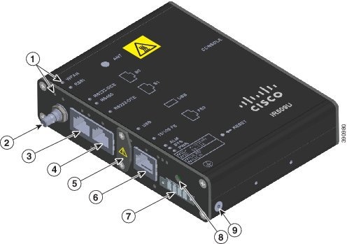
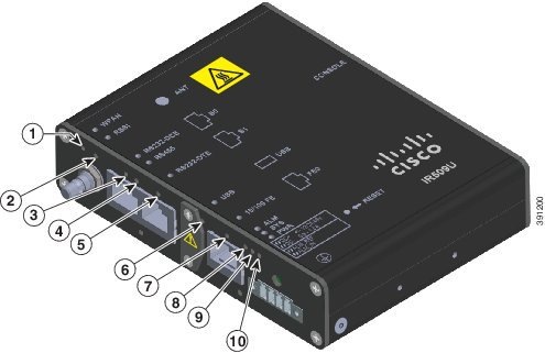
Front Panel—WPAN Gateway
This section describes the front panel components shown in Figure 1-1:
- Status LEDS
- Antenna Connector
- RS232/RS485 DCE Port
- RS232 DTE Port
- USB Port
- 10/100 Fast Ethernet Port
- Power and Alarm Connector
- Reset Switch
Figure 1-1 Front Panel of WPAN Gateway IR509UWP-915/K9 Model
|
|
|
||
|
|
|
Power1 and alarm connector |
|
|
|
|
||
|
|
|
||
|
|
|
|
|
Status LEDS
The status LEDs provide status information on the WPAN gateway status, activity, and performance. For more information, see the “WPAN Gateway LEDs” section.
Antenna Connector
The antenna connector is a QMA, panel-mounted, 50-ohm connector for connecting the antenna to the WPAN gateway.
RS232/RS485 DCE Port
The RS232/RS485 DCE port is a configurable serial port for connecting a serial device to the WPAN Gateway. The Connected Grid Network Management System (CG-NMS) application is used to configure the port.
The port can be configured for RS232 or RS485. RS232 operates in full duplex mode on the port, and RS485 operates in half duplex or full duplex mode. You can also use the CG-NMS to obtain statistics about the serial port including bytes sent and bytes received information.
For information about connecting to the RS232-DCE or RS485 port, see the “Connecting to the RS232DCE/RS485 or RS232-DTE Ports” section.
RS232 DTE Port
The RS232 DTE port is a configurable serial port for connecting a serial device to the WPAN Gateway. The Connected Grid Network Management System (CG-NMS) application is used to configure the port.
You can also use the CG-NMS to obtain statistics about the port including bytes sent and bytes received information.
For information about connecting to the RS232 DTE port, see the “Connecting to the RS232DCE/RS485 or RS232-DTE Ports” section.
USB Port
For information about the USB port, see the Cisco IR 500 Series WPAN Gateway and Range Extender Release Notes on Cisco.com.
For information about connecting to the USB port, see the “Connecting to the USB Port” section.
10/100 Fast Ethernet Port
The 10/100 Fast Ethernet port provides IPv4 connectivity to devices. Connectivity over the IPv6-based Field Area Network (FAN) is provided using the Mapping of Address and Port using Translation (MAP-T) protocol by the WPAN gateway.
For information about connecting to the Fast Ethernet 10/100 port, see the “Connecting to the 10/100 Fast Ethernet Port” section.
Power and Alarm Connector
You connect the DC power and alarm connections to the WPAN gateway through the front panel connector. The gateway requires a DC power supply. The power connector labeling is on the connector. Figure 1-2 shows the power and alarm connector.
Figure 1-2 WPAN Gateway Power and Alarm Connector
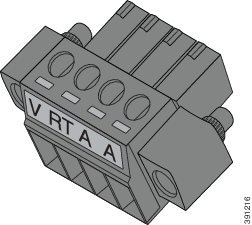
Table 1-3 describes the power connections.
|
|
|
|---|---|
The alarm input connections allow the WPAN gateway to be wired to monitor an alarm condition. The alarm can be configured by the Connected Grid Network Management System to operate on a normally open (NO) or normally closed (NC) basis. Table 1-4 describes the alarm connections.
The alarm input could be used to detect a remote alarm condition such as a normally locked cabinet door being opened or tampered with, or an attached electromechanical device losing power.
For information about wiring the power and alarm connector, see the “Wiring the WPAN Gateway DC Power” section and the “Wiring the WPAN Gateway Alarm” section.
Reset Switch
The reset switch is used to rest the WPAN gateway to its factory settings. To activate the reset, press the reset switch for three seconds.
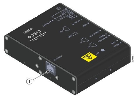
Rear Panel—WPAN Gateway
This section describes the WPAN gateway rear panel components shown in Figure 1-3:
Figure 1-3 Rear Panel of WPAN Gateway IR509UWP-915/K9 Model
|
|
You can connect the WPAN gateway to a PC or laptop through the RJ-45 console port.
For information about connecting to the console port, see the “Connecting to the WPAN Gateway Console Port” section.
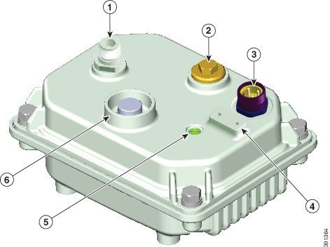
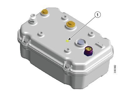
Bottom Panel—WPAN Range Extender
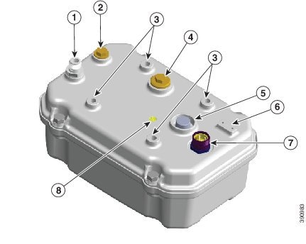
This section describes the WPAN Range Extender bottom panel components shown in Figure 1-4:
- Antenna Connector
- Hard Points
- Console Port
- Protective Vent Port
- Ground Connection
- Power Connector
- System LED
Figure 1-4 Bottom Panel of Base Range Extender IR529WP-915S/K9 Model
|
|
|
||
|
|
|
||
|
|
Power2 connector |
|
|
|
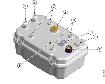
Figure 1-5 Bottom Panel of Advanced Range Extender IR529UBWP-915S/K9 Model
|
|
|
||
|
|
|
||
|
|
Hard points M8 x 1.25 mm, 8 mm deep (5/16-18 in., 5/16 in. deep) |
|
Power3 connector |
|
|
|
|
|
Figure 1-6 Bottom Panel of Advanced Range Extender IR529UBWP-915D/K9 and IR529UWP-915D/K9 Models
|
|
|
||
|
|
|
||
|
|
Hard points M8 x 1.25 mm, 8 mm deep (5/16-18 in., 5/16 in. deep) |
|
Power4 connector |
|
|
|
|
|
Antenna Connector
Hard Points
The hard points are used for alternate mounting or as attach points for additional equipment.
Console Port
You can connect the WPAN range extender to a PC or laptop through the RJ-45 console port.
The console port is covered with a cable port seal—this is a liquid tight cover for protecting the WPAN range extender from environmental elements.
For information about connecting to the console port, see the “Connecting to the WPAN Range Extender Console Port” section.
Protective Vent Port
The protective vent port relieves pressure buildup inside the extender chassis that can be caused by changing temperatures in the installation environment. This prevents pressure from building up and damaging enclosure seals and the potential exposure of sensitive components to water. The vent also protects the extender interior from dust, dirt, water, and other environmental elements.
Ground Connection
The ground connection is used to ground the WPAN extender. A provided wired grounding lug is attached to the ground connection using screws. The other end of the ground wire is connected to an earth ground, such as a grounding rod or an appropriate grounding point on a pole that is grounded.
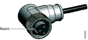
Power Connector
The power connector connects to the Cisco AC power cable shipped with the unit. Figure 1-7 shows the 3 pin AC power connector.
Figure 1-7 WPAN Range Extender AC Power Connector
System LED
The system LED provide status information on the WPAN range extender activity and performance.
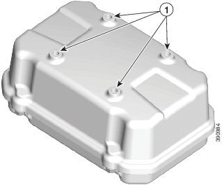
Top Panel—WPAN Range Extender
This section describes the WPAN range extender top panel components shown in .
Figure 1-8 Top Panel of Base and Advanced Range Extender
|
|
The mounting holes are for attaching the range extender to the bracket supplied for mounting the device on a pole or wall.
LEDs
WPAN Gateway LEDs
You can use the LEDs to monitor the gateway status, activity, and performance. Figure 1-9 shows the front panel LEDs.

Note![]() Each front panel LED has an equivalent matching LED on the top panel (See Figure 1-1).
Each front panel LED has an equivalent matching LED on the top panel (See Figure 1-1).
Figure 1-9 WPAN Gateway Front Panel LEDS
|
|
|
||
|
|
|
||
|
|
|
||
|
|
|
||
|
|
|
WPAN LED
The WPAN LED shows the status of the WPAN interface. Table 1-5 lists the WPAN LED colors and their meanings.
|
|
|
|
|---|---|---|
|
|
|
|
Default route is available and DHCPv6 configuration is starting. |
||
RSSI LED
The RSSI LED shows the WPAN received signal strength at the WPAN interface. Table 1-6 lists the RSSI LED colors and their meanings.
|
|
|
|
|---|---|---|
|
|
|
|
RS232-DCE LED
The RS232-DCE LED shows the status of the RS232 serial communication on the port. Table 1-7 lists the RS232-DCE LED colors and their meanings.
RS485 LED
The RS485 LED shows the status of the RS485 serial communication on the port. Table 1-7 lists the RS485 LED colors and their meanings.
USB LED
The USB Led shows the status of the USB port. Table 1-9 lists the USB LED Colors and their meanings.
RS232-DTE LED
The RS232-DTE LED shows the status of the RS232-DTE port. Table 1-10 lists the USB LED Colors and their meanings.
|
|
|
|---|---|
RS232-DTE is not selected as the active DA2 Port (Which means that either the USB is selected as the active DA2 Port or the DA2 port is turned off completely). |
|
10/100 FE LED
The 10/100 FE LED shows the connectivity status of the 10/100 FE port. Table 1-11 lists the 10/100 FE LED colors and their meanings.
Power LED
The Power LED shows the power status of the WPAN gateway. Table 1-12 lists the power LED colors and their meanings.
System LED
The System LED indicates the system status. Table 1-14 lists the system LED colors and their meanings.
|
|
|
|---|---|
Alarm LED
The Alarm LED indicates the alarm status. Table 1-14 lists the alarm LED colors and their meanings.
|
|
|
|---|---|
WPAN Range Extender LEDs
The WPAN Range Extender has one LED—a System LED.
Figure 1-10 WPAN Range Extender Status LED
|
|
The System LED indicates the system status. lists the system LED colors and their meanings.
|
|
|
|---|---|
Management Options
Connected Grid Network Management System
The Cisco Connected Grid Network Management System (CG-NMS) manages the WPAN gateway and WPAN range extender devices. CG-NMS provides:
- Backend network configuration
- Device monitoring
- Event notification services
- Network firmware upgrades
- Power outage/restoration notification
- Meter registration
CG-NMS also retrieves statistics on network traffic from the devices. For more information on CG-NMS and configuring the devices, see the Cisco Connected Grid Network Management System User Guide on Cisco.com.
CSMP Client
CSMP Client is a GUI field tool used to manage and monitor the WPAN gateway and WPAN range extender hardware and networking information.
The field tool provides two functions, "GET" and “POST” to obtain status and performance information about the devices in real-time. It can be used as a diagnostic tool to check a single device or the whole mesh network.
The field tool has three connection modes to connect a WPAN gateway or WPAN range extender:
Connected Grid Device Manager
Connected Grid Device Manager (CG-DM) is a GUI field tool used to troubleshoot, configure and to update firmware images on WPAN Gateway devices.
 Feedback