- Preface
- Cisco ASR1000-RP3 Module Overview
- Preparing to Install the Cisco ASR1000-RP3 Module
- Installing the Cisco ASR1000-RP3 Module
- Software Licensing on Cisco ASR1000-RP3 Module
- Configuring the Cisco ASR1000-RP3 Module
- Upgrading the Cisco ASR1000-RP3 Module
- Upgrading the ROMMON
- Removing and Replacing FRUs from the Cisco ASR1000-RP3 Module
Cisco ASR 1000 Route Processor 3 Installation and Configuration Guide
Bias-Free Language
The documentation set for this product strives to use bias-free language. For the purposes of this documentation set, bias-free is defined as language that does not imply discrimination based on age, disability, gender, racial identity, ethnic identity, sexual orientation, socioeconomic status, and intersectionality. Exceptions may be present in the documentation due to language that is hardcoded in the user interfaces of the product software, language used based on RFP documentation, or language that is used by a referenced third-party product. Learn more about how Cisco is using Inclusive Language.
- Updated:
- November 8, 2016
Chapter: Cisco ASR1000-RP3 Module Overview
Cisco ASR1000-RP3 Module Overview
Overview
The Cisco ASR 1000 Series Route Processor 3 (Cisco ASR1000-RP3) module runs the network operating system, BINOS kernel, and the IOSD (IOS daemon). The Cisco ASR1000-RP3 module is supported on the Cisco ASR 1013, Cisco ASR 1006-X, and Cisco ASR 1009-X routers.
Figure 1-1 shows the front panel of the Cisco ASR1000-RP3 module.
Figure 1-1 Cisco ASR1000-RP3 Front Panel

The Cisco ASR1000-RP3 module supports:
- the running of the router control plane, including network control packets, and connection setup
- the synchronization of the active and standby Cisco ASR1000-RP3 and Cisco ASR 1000 Series ESP master and standby (tasks include switchover from failing master to standby)
- code storage, management, and upgrade
- On-board failure logging (OBFL) with 2 MB of memory
- the downloading of operational code for SPA interface processors (SIPs), modular interface processors (MIPs), and Cisco ASR 1000 Series ESP over Ethernet out of band channel (EOBC), which is used for communication between the control processors on the Cisco ASR 1000 Series Routers
- command line interface (CLI), alarm, network management, logging, and statistics aggregation
- punt path processing of packets not supported by the embedded services processors
- configuration repository along with a solid-state drive (SSD) for logging system statistics, records, events, errors, and dump
- the management interfaces of the platform including Dual Asynchronous Receiver/Transmitter (DUART) that is used for the CON and AUX serial ports. The MGMT Ethernet (ENET) management ports, CLI, status indicators, BITS interface, reset switch, Audible Cutoff (ACO) button, USB ports for secure key distribution, and a mini-USB Console port to connect to a USB host (laptop)
- field-replaceable unit (FRU) with online insertion and removal (OIR)
- the chassis management including activation and initialization of the other cards, selection or switchover of active versus standby cards, image management and distribution, logging facilities, distribution of user configuration information, and alarm control
- the control signals for monitoring the health of power entry modules, shutting down the power and driving alarm relays located on the power entry modules
- redundancy

Note![]() Although the Cisco ASR1000-RP3 and Cisco ASR1000-RP2 modules can coexist in the same chassis for a short time when you are installing the Cisco ASR1000-RP3 module, you can only have one type of RP in a chassis. For detailed information on the software upgrade procedures, see Software Upgrade Process chapter of the Cisco ASR 1000 Series Aggregation Services Routers Software Configuration Guide.
Although the Cisco ASR1000-RP3 and Cisco ASR1000-RP2 modules can coexist in the same chassis for a short time when you are installing the Cisco ASR1000-RP3 module, you can only have one type of RP in a chassis. For detailed information on the software upgrade procedures, see Software Upgrade Process chapter of the Cisco ASR 1000 Series Aggregation Services Routers Software Configuration Guide.
Understanding Redundancy
The Cisco ASR1000-RP3 module, the Cisco ASR1000 ESPs, and power supplies support redundancy. Only one RP and one ESP are considered active at a time and no load sharing is performed. However, the non-active RP or ESP is maintained in a warm standby state so that it can take over the active role as quickly as possible if necessary.
The following combination of components are supported:
In a fully redundant chassis, each RP is separately connected to each FP and I/O card slot over separate point-to-point connections of the system interconnect over the midplane. The selection of the active RP is made separately from the selection of the active ESP.
Supported and Unsupported Platforms, ESPs and Line Cards
Table 1-1 lists the platforms in which the Cisco ASR1000-RP3 module is supported or unsupported, the ESPs and line cards that are supported or unsupported.
|
|
|
|
|---|---|---|
Cisco ASR 1000 Series Route Processor Differences
The Cisco ASR 1000 RPs receive and transmit network packets through active embedded services processors. Table 1-2 describes the differences between the Cisco ASR1000-RP1, Cisco ASR1000-RP2, and Cisco ASR1000-RP3 modules.
Hardware Features
The Cisco ASR1000-RP3 module provides the following enhancements compared to Cisco ASR1000-RP2 module:
- Supports up to 64 GB of memory with error detection and correction
- Provides Enhanced Serdes Interconnect (ESI) at 25 Gbps
- Contains 100 GB SSD bulk storage
- Provides 8 GB bootflash
- Comes with 8 GB of DRAM memory and can be upgraded to 16 GB, 32 GB, or 64 GB
In addition, the Cisco ASR1000-RP3 module supports the following functionalities:
- On-board Failure Logging (OBFL) with 2MB of memory
- Cisco ASR 1000 Series Router system architecture and midplane
- Gigibit Ethernet switches for Ethernet Out-of-Band Channel (EOBC) communication and boot-up of the SIPs, MIPs, and Cisco ASR 1000 Series ESP
- Runs Cisco IOS network control plane (routing protocol, connections setup)
- Cisco IOS punt packet forwarding
- Active/Standby Cisco ASR1000-RP3 module and Cisco ASR 1000 Series ESP selection
- Code storage and download operational code to Cisco ASR 1000 Series ESP and Cisco ASR 1000 SIP
- Front panel support: Console, 10/100 Management port, two USB ports, mini-USB port, CON port, and AUX port.
The Cisco ASR 1000 Series Routers have one Gigabit Ethernet Management Ethernet interface on each RP. The purpose of this interface is to allow users to perform management tasks on the router; it is an interface that does not forward network traffic but can otherwise access the router, often through Telnet and SSH, and perform most management tasks on the router. The interface is useful before a router has begun routing, or in troubleshooting scenarios when the SPA interfaces are inactive
Note the following aspects of the Management Ethernet interface:
–![]() Each RP has a Management Ethernet interface, but only the active RP has an accessible Management Ethernet interface (the standby RP can be accessed using the console port, however).
Each RP has a Management Ethernet interface, but only the active RP has an accessible Management Ethernet interface (the standby RP can be accessed using the console port, however).
–![]() IPv4, IPv6, and ARP are the only routed protocols supported for the interface.
IPv4, IPv6, and ARP are the only routed protocols supported for the interface.
–![]() The interface provides a method of access to the router even if the SPA interfaces or the IOS processes are down.
The interface provides a method of access to the router even if the SPA interfaces or the IOS processes are down.
- A console port that can run up to 115.2 kbps with hardware flow control. One port is used as the CONSOLE port for secure configuration and status display. The default BAUD rate for the CONSOLE port should be set at 9600 BAUD. Both console and auxiliary ports are asynchronous serial ports.
Note![]() In Cisco IOS XE Denali 16.3.1 release, BITS T1/E1 is not supported on RP3. This support will be provided in future releases.
In Cisco IOS XE Denali 16.3.1 release, BITS T1/E1 is not supported on RP3. This support will be provided in future releases.
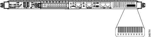
Model Number Location
Figure 1-2 shows the location of the model number on the Cisco ASR1000-RP3 module.
Figure 1-2 Cisco ASR1000-RP3 Model Number Location
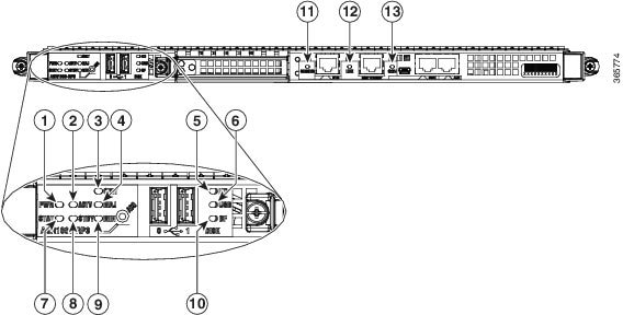
LEDs
Figure 1-3 shows the Cisco ASR1000-RP3 LEDs.
Figure 1-3 Cisco ASR1000-RP3 LEDs
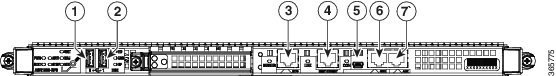
Management and Storage Connections
Figure 1-4 shows the Cisco ASR1000-RP3 management and storage connections.
Figure 1-4 Cisco ASR1000-RP3 Connectors
 Feedback