- Preface
- Cisco ASR1000-RP3 Module Overview
- Preparing to Install the Cisco ASR1000-RP3 Module
- Installing the Cisco ASR1000-RP3 Module
- Software Licensing on Cisco ASR1000-RP3 Module
- Configuring the Cisco ASR1000-RP3 Module
- Upgrading the Cisco ASR1000-RP3 Module
- Upgrading the ROMMON
- Removing and Replacing FRUs from the Cisco ASR1000-RP3 Module
Cisco ASR 1000 Route Processor 3 Installation and Configuration Guide
Bias-Free Language
The documentation set for this product strives to use bias-free language. For the purposes of this documentation set, bias-free is defined as language that does not imply discrimination based on age, disability, gender, racial identity, ethnic identity, sexual orientation, socioeconomic status, and intersectionality. Exceptions may be present in the documentation due to language that is hardcoded in the user interfaces of the product software, language used based on RFP documentation, or language that is used by a referenced third-party product. Learn more about how Cisco is using Inclusive Language.
- Updated:
- November 8, 2016
Chapter: Installing the Cisco ASR1000-RP3 Module
Installing the Cisco ASR1000-RP3 Module
This chapter contains the following topics:
- Installing the Cisco ASR1000-RP3 Module in the Router
- Removing the Cisco ASR1000-RP3 Module from the Router

Warning![]() Only trained and qualified personnel should be allowed to install, replace, or service this equipment. Statement 1030
Only trained and qualified personnel should be allowed to install, replace, or service this equipment. Statement 1030
Warning![]() During this procedure, wear grounding wrist straps to avoid ESD damage to any card. Do not directly touch the backplane with your hand or any metal tool, or you could shock yourself. Statement 94
During this procedure, wear grounding wrist straps to avoid ESD damage to any card. Do not directly touch the backplane with your hand or any metal tool, or you could shock yourself. Statement 94
Installing the Cisco ASR1000-RP3 Module in the Router
The Cisco ASR1000-RP3 module can be installed in Slot R1 and Slot R0 of the Cisco ASR 1013, Cisco ASR 1006-X, and Cisco ASR 1009-X routers.
Step 1![]() Attach an ESD-preventive wrist strap between you and an unfinished chassis surface.
Attach an ESD-preventive wrist strap between you and an unfinished chassis surface.
Step 2![]() Remove the new RP from its static shielding bag.
Remove the new RP from its static shielding bag.
Step 3![]() Using both hands, grasp the RP by its metal carrier and orient it so that its printed circuit board components are upward.
Using both hands, grasp the RP by its metal carrier and orient it so that its printed circuit board components are upward.
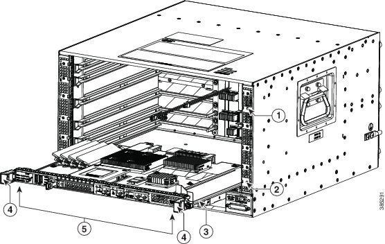
Figure 3-1 Cisco ASR1000-RP3 With Metal Carrier and Handles
|
|
|
||
|
|
|
||
|
|
|

Step 4![]() Align the left and right edges of the RP printed circuit board between the RP slot guides.
Align the left and right edges of the RP printed circuit board between the RP slot guides.
Step 5![]() Gently slide the RP all the way into its chassis slot until you feel the connectors seat with the router midplane.
Gently slide the RP all the way into its chassis slot until you feel the connectors seat with the router midplane.
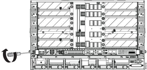
Step 6![]() Seat the RP in the router midplane by tightening its captive installation screws with a number 2 Phillips or a 3/16-inch flat-blade screwdriver as shown in Figure 3-2.
Seat the RP in the router midplane by tightening its captive installation screws with a number 2 Phillips or a 3/16-inch flat-blade screwdriver as shown in Figure 3-2.
Figure 3-2 Cisco ASR1000-RP3 Installed in the Chassis
Removing the Cisco ASR1000-RP3 Module from the Router

Note![]() If you have two RPs in the router and you want to remove one, do not power down the router. Remove the RP and then insert a new one; high availability provides for the other RP to take on the processing tasks for the router.
If you have two RPs in the router and you want to remove one, do not power down the router. Remove the RP and then insert a new one; high availability provides for the other RP to take on the processing tasks for the router.
Step 1![]() Slip on an ESD-preventive wrist strap and attach it to a chassis surface.
Slip on an ESD-preventive wrist strap and attach it to a chassis surface.
Step 2![]() If connected, remove any I/O cables from the RP.
If connected, remove any I/O cables from the RP.
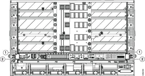
Step 3![]() Using a number 2 Phillips or a 3/16-inch flat-blade screwdriver, loosen the two captive screws on the faceplate of the RP.
Using a number 2 Phillips or a 3/16-inch flat-blade screwdriver, loosen the two captive screws on the faceplate of the RP.
Step 4![]() Using the handles on both sides of the module, with both hands gently slide the module out of the chassis slot.
Using the handles on both sides of the module, with both hands gently slide the module out of the chassis slot.
Figure 3-3 Cisco ASR1000-RP3 Handles
|
|
|
Step 5![]() Place the RP module on an antistatic surface with its printed circuit board components facing upward or in a static shielding bag.
Place the RP module on an antistatic surface with its printed circuit board components facing upward or in a static shielding bag.
Note![]() If you are returning the RP to the factory, immediately place it in a static shielding bag.
If you are returning the RP to the factory, immediately place it in a static shielding bag.
 Feedback