Cisco IAD2430 Series Integrated Access Device Hardware Installation Guide
Bias-Free Language
The documentation set for this product strives to use bias-free language. For the purposes of this documentation set, bias-free is defined as language that does not imply discrimination based on age, disability, gender, racial identity, ethnic identity, sexual orientation, socioeconomic status, and intersectionality. Exceptions may be present in the documentation due to language that is hardcoded in the user interfaces of the product software, language used based on RFP documentation, or language that is used by a referenced third-party product. Learn more about how Cisco is using Inclusive Language.
- Updated:
- October 11, 2004
Chapter: Chapter 3: Installing Cisco IAD2430 Series IADs
- Safety Recommendations
- Site Log
- Keeping Track—Checklist
- Mounting Tools and Equipment
- Unpacking and Inspection
- Rack-Mounting the Chassis
- Wall-Mounting the Chassis
- Desktop-Mounting the Chassis
- Installing the Ground Connection
- Installing a WAN or Voice Card
- Connecting Cables
- LAN and Power Cables
- Connecting the Input Power
- Connecting the Console Port to a PC or an ASCII Terminal
- Connecting the Auxiliary Port to a Modem
- Connecting the Fast Ethernet Port to the Fast Ethernet Switch
- WAN and Voice Cables
- Connecting the RJ-21 Cable in the Velcro Harness
- Connecting a Serial Interface Port to a CSU/DSU or a Synchronous Modem
- Connecting a T1/E1-WAN Port to the Network Demarcation Device
- Connecting the Analog Voice Interface to a Distribution Panel
- Connecting the Digital Voice Port to a T1/E1-PBX
Installing Cisco IAD2430 Series IADs
This chapter contains the procedures for installing your Cisco IAD2430 series integrated access device (IAD) and consists of the following sections:
•![]() Installing the Ground Connection
Installing the Ground Connection
•![]() Installing a WAN or Voice Card
Installing a WAN or Voice Card
•![]() Ports, Connectors, and Pinouts
Ports, Connectors, and Pinouts
•![]() Remote Terminal Connections (If Applicable)
Remote Terminal Connections (If Applicable)

Tip ![]() While you perform this installation, record your progress and site information. See the suggested format in the "Keeping Track—Checklist" section.
While you perform this installation, record your progress and site information. See the suggested format in the "Keeping Track—Checklist" section.

Warning ![]() Only trained and qualified personnel should be allowed to install, replace, or service this equipment. Statement 1030
Only trained and qualified personnel should be allowed to install, replace, or service this equipment. Statement 1030
Warning ![]() Read the installation instructions before connecting the system to the power source. Statement 1004
Read the installation instructions before connecting the system to the power source. Statement 1004
Safety Recommendations
The following information is included to alert you to safety recommendations and best practices when working with this equipment.
Maintaining Safety with Electricity
Follow these guidelines when working on equipment powered by electricity.
Warning ![]() Do not work on the system or connect or disconnect cables during periods of lightning activity. Statement 1001
Do not work on the system or connect or disconnect cables during periods of lightning activity. Statement 1001
Warning ![]() Blank faceplates and cover panels serve three important functions: they prevent exposure to hazardous voltages and currents inside the chassis; they contain electromagnetic interference (EMI) that might disrupt other equipment; and they direct the flow of cooling air through the chassis. Do not operate the system unless all cards, faceplates, front covers, and rear covers are in place. Statement 1029
Blank faceplates and cover panels serve three important functions: they prevent exposure to hazardous voltages and currents inside the chassis; they contain electromagnetic interference (EMI) that might disrupt other equipment; and they direct the flow of cooling air through the chassis. Do not operate the system unless all cards, faceplates, front covers, and rear covers are in place. Statement 1029
General Safety Practices
Follow these guidelines to ensure personal safety and protect the equipment:
•![]() Keep the chassis area clear and dust-free during and after installation.
Keep the chassis area clear and dust-free during and after installation.
•![]() Put the removed chassis cover in a safe place.
Put the removed chassis cover in a safe place.
•![]() Keep tools away from walk areas where you and others could fall over them.
Keep tools away from walk areas where you and others could fall over them.
•![]() Do not wear loose clothing that could get caught in the chassis.
Do not wear loose clothing that could get caught in the chassis.
•![]() Wear safety glasses if you are working under any conditions that might be hazardous to your eyes.
Wear safety glasses if you are working under any conditions that might be hazardous to your eyes.
Warning ![]() This equipment must be installed and maintained by service personnel as defined by AS/NZS 3260. Incorrectly connecting this equipment to a general-purpose outlet could be hazardous. The telecommunications lines must be disconnected 1) before unplugging the main power connector or 2) while the housing is open, or both. Statement 1043
This equipment must be installed and maintained by service personnel as defined by AS/NZS 3260. Incorrectly connecting this equipment to a general-purpose outlet could be hazardous. The telecommunications lines must be disconnected 1) before unplugging the main power connector or 2) while the housing is open, or both. Statement 1043
Safety Tips
Use these tips as safety guidelines when installing or working around this equipment.
•![]() Locate the emergency power-off switch for the room in which you are working. Then, if an electrical accident occurs, you can act quickly to turn off the power.
Locate the emergency power-off switch for the room in which you are working. Then, if an electrical accident occurs, you can act quickly to turn off the power.
•![]() Disconnect all power before installing or removing a chassis.
Disconnect all power before installing or removing a chassis.
•![]() Do not work alone if potentially hazardous conditions exist.
Do not work alone if potentially hazardous conditions exist.
•![]() Never assume that power is disconnected from a circuit. Always check.
Never assume that power is disconnected from a circuit. Always check.
•![]() Look carefully for possible hazards in your work area, such as moist floors, ungrounded power extension cables, and missing safety grounds.
Look carefully for possible hazards in your work area, such as moist floors, ungrounded power extension cables, and missing safety grounds.
•![]() If an electrical accident occurs, proceed as follows:
If an electrical accident occurs, proceed as follows:
–![]() Use caution; do not become a victim yourself.
Use caution; do not become a victim yourself.
–![]() Turn off power to the system.
Turn off power to the system.
–![]() If possible, send another person to get medical aid. Otherwise, assess the condition of the victim and then call for help.
If possible, send another person to get medical aid. Otherwise, assess the condition of the victim and then call for help.
–![]() Determine if the person needs rescue breathing or external cardiac compressions; then take appropriate action.
Determine if the person needs rescue breathing or external cardiac compressions; then take appropriate action.
Preventing Electrostatic Discharge Damage
Electrostatic discharge (ESD) can damage equipment and impair electrical circuitry. ESD occurs when electronic components are improperly handled; it can result in complete or intermittent failures.
Always follow ESD-prevention procedures when removing and replacing components.
•![]() Ensure that the chassis is electrically connected to earth ground.
Ensure that the chassis is electrically connected to earth ground.
•![]() Wear an ESD-preventive wrist strap, ensuring that it makes good skin contact.
Wear an ESD-preventive wrist strap, ensuring that it makes good skin contact.
•![]() Connect the clip to the ESD-strap connection jack (to the left of the power switch on the back of the chassis) or to an unpainted chassis frame surface.
Connect the clip to the ESD-strap connection jack (to the left of the power switch on the back of the chassis) or to an unpainted chassis frame surface.

Site Log
We recommend that you maintain a Site Log to record all actions relevant to the system. Site Log entries might include the following:
•![]() Installation—Print a copy of the Installation Checklist and insert it into the Site Log.
Installation—Print a copy of the Installation Checklist and insert it into the Site Log.
•![]() Upgrades and maintenance—Use the Site Log to record ongoing maintenance and expansion history. Update the Site Log to reflect the following:
Upgrades and maintenance—Use the Site Log to record ongoing maintenance and expansion history. Update the Site Log to reflect the following:
–![]() Configuration changes
Configuration changes
–![]() Maintenance schedules, requirements, and procedures performed
Maintenance schedules, requirements, and procedures performed
–![]() Comments, notes, and problems
Comments, notes, and problems
–![]() Changes and updates to the Cisco IOS software
Changes and updates to the Cisco IOS software
Keeping Track—Checklist
We recommend that you use an installation checklist and maintain a Site Log.
Installation Checklist
The Installation Checklist (see Figure 3-1) lists the tasks for installing a Cisco IAD. Print a copy of this checklist and mark the entries as you complete each task. For each Cisco IAD, include a copy of the Installation Checklist in your Site Log.
Figure 3-1 Installation Checklist
Installation Checklist for site ______________________________________________
Cisco IAD name/serial number _____________________________________________
Mounting Tools and Equipment
Obtain the following tools and parts needed for installing a Cisco IAD2430 series IAD:
•![]() Standard flat-blade screwdriver as required for attaching brackets to rack or wall.
Standard flat-blade screwdriver as required for attaching brackets to rack or wall.
•![]() Phillips screwdriver for attaching brackets to the IAD.
Phillips screwdriver for attaching brackets to the IAD.
•![]() Mounting brackets and screws for 24-inch rack, if required.
Mounting brackets and screws for 24-inch rack, if required.
–![]() Four telco machine screws for installing the chassis in a rack (use the screw size required by the rack).
Four telco machine screws for installing the chassis in a rack (use the screw size required by the rack).
•![]() Screws and anchors for wall mounting, if required.
Screws and anchors for wall mounting, if required.
–![]() Eight wood screws or other fasteners for installing the chassis on a wall. An additional starter screw can be used to facilitate wall-mounting (does not include Cisco IAD2435 IAD).
Eight wood screws or other fasteners for installing the chassis on a wall. An additional starter screw can be used to facilitate wall-mounting (does not include Cisco IAD2435 IAD).
–![]() For Cisco IAD2435 IAD—two number-six, 3/4-inch (M3.5 x 20-mm) screws.
For Cisco IAD2435 IAD—two number-six, 3/4-inch (M3.5 x 20-mm) screws.
•![]() ESD-preventive wrist strap
ESD-preventive wrist strap
In addition, you might need the following external equipment:
•![]() Console terminal, or personal computer with terminal emulation software
Console terminal, or personal computer with terminal emulation software
•![]() PC running terminal emulation software for administrative access
PC running terminal emulation software for administrative access
•![]() Modem for remote access
Modem for remote access
•![]() Analog voice RJ-21 cable
Analog voice RJ-21 cable
•![]() Digital voice RJ-48 T1/E1 cable
Digital voice RJ-48 T1/E1 cable
•![]() Serial, RJ-48, or RJ-45 cables for connecting WAN interface cards (WICs) or voice interface cards (VICs)
Serial, RJ-48, or RJ-45 cables for connecting WAN interface cards (WICs) or voice interface cards (VICs)
•![]() CSU/DSU for the serial interfaces
CSU/DSU for the serial interfaces
•![]() Ethernet switch
Ethernet switch
•![]() Modem for remote configuration
Modem for remote configuration

Note ![]() Serial cables use the Cisco 12-in-1 connector on the WAN connection end.
Serial cables use the Cisco 12-in-1 connector on the WAN connection end.
Unpacking and Inspection
Do not unpack the Cisco IAD2430 series IAD until you are ready to install it. If the installation site is not ready, keep the chassis in its shipping container to prevent accidental damage.
The IAD, cables, and any optional equipment you ordered might be shipped in more than one container. When you unpack each shipping container, check the packing list to ensure that you received all the following items:
•![]() Cisco IAD2430 series IAD
Cisco IAD2430 series IAD
•![]() Power cord
Power cord
Note ![]() Power cords vary, depending upon local requirements.
Power cords vary, depending upon local requirements.
•![]() RJ-45-to-DB-25 adapter cable (labeled CON)
RJ-45-to-DB-25 adapter cable (labeled CON)
•![]() RJ-45-to-DB-9 adapter cable (labeled AUX)
RJ-45-to-DB-9 adapter cable (labeled AUX)
•![]() Rack-mounting brackets for 19-inch rack (one pair) with screws for attaching to chassis
Rack-mounting brackets for 19-inch rack (one pair) with screws for attaching to chassis
Note ![]() Rack-mount brackets for 19-inch rack, NEBS grounding kit, and chassis guard for wall-mounting applications are not included with the Cisco IAD2435-8FXS.
Rack-mount brackets for 19-inch rack, NEBS grounding kit, and chassis guard for wall-mounting applications are not included with the Cisco IAD2435-8FXS.
•![]() Grounding lug and fasteners
Grounding lug and fasteners
Inspect all items for shipping damage. If anything appears damaged, or if you encounter problems when installing or configuring your system, contact a customer service representative. (See the "Obtaining Documentation and Submitting a Service Request" section on page xvi.)
Rack-Mounting the Chassis
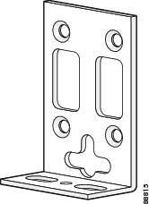
Your chassis ship with a pair of brackets for use with a 19-inch rack or for use for wall mounting on the wall (see Figure 3-9) (Brackets are not included with the Cisco IAD2435 IAD chassis (see Figure 3-3), but can be ordered through Cisco.). The bracket is shown in Figure 3-2.
Figure 3-2 Quick Installation Bracket for all Cisco IAD2430 Series Routers Except for Cisco IAD2435 IAD
Note ![]() Rack-mount brackets for 19-inch rack, NEBS grounding kit, and chassis guard for wall-mounting applications are not included with the Cisco IAD2435-8FXS.
Rack-mount brackets for 19-inch rack, NEBS grounding kit, and chassis guard for wall-mounting applications are not included with the Cisco IAD2435-8FXS.
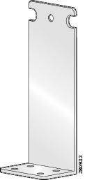
Figure 3-3 Quick Installation Bracket for Cisco IAD2435-8FXS Routers
Mounting Screws
Two sets of mounting screws are provided, in separate packages (Mounting screws are not included with the Cisco IAD2435 IAD chassis). Take care to use each screw type, and washers as needed, in the appropriate locations. Table 3-1 clarifies the differences between rack-mounting and wall-mounting screws.
Attaching the Brackets
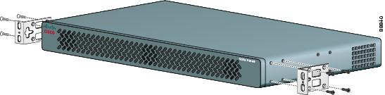
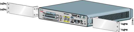
To install the chassis in a rack with the front panel forward, attach the brackets as shown in Figure 3-4.
Figure 3-4 19-Inch Rack Installation—Front Panel Forward
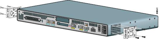
To install the chassis in a rack with the back panel forward, attach the brackets as shown in Figure 3-5.
Figure 3-5 19-Inch Rack Installation—Back Panel Forward
To install the chassis in a center-mount telco rack, attach the brackets as shown in Figure 3-6.
Figure 3-6 Telco 19-Inch Rack Installation—Back Panel Forward

To install the Cisco IAD2435 chassis in a rack with the back panel forward, attach the brackets as shown in Figure 3-7.
Figure 3-7 IAD2435 Rack Installation with Back Panel Forward
Installing the Cisco IAD2430 Series IADs in a Rack
The following warning applies only when the unit is rack-mounted:
Warning ![]() To prevent bodily injury when mounting or servicing this unit in a rack, you must take special precautions to ensure that the system remains stable. The following guidelines are provided to ensure your safety:
To prevent bodily injury when mounting or servicing this unit in a rack, you must take special precautions to ensure that the system remains stable. The following guidelines are provided to ensure your safety:
This unit should be mounted at the bottom of the rack if it is the only unit in the rack.
When mounting this unit in a partially filled rack, load the rack from the bottom to the top with the heaviest component at the bottom of the rack.
If the rack is provided with stabilizing devices, install the stabilizers before mounting or servicing the unit in the rack. Statement 1006
Warning ![]() Take care when connecting units to the supply circuit so that wiring is not overloaded. Statement 1018
Take care when connecting units to the supply circuit so that wiring is not overloaded. Statement 1018
To rack-mount the chassis, follow these steps:
Step 1 ![]() Choose one of the methods shown in Figure 3-4, Figure 3-5, Figure 3-6, or Figure 3-7, and attach the long side of the mounting brackets to the chassis, as shown.
Choose one of the methods shown in Figure 3-4, Figure 3-5, Figure 3-6, or Figure 3-7, and attach the long side of the mounting brackets to the chassis, as shown.
Screws are included for attaching the brackets to the chassis, but not for installing the chassis in a rack or on a wall. You need four additional machine screws to install the chassis in a rack. Use the screw size required by your rack. After the brackets are secured to the chassis, you can rack-mount the chassis.
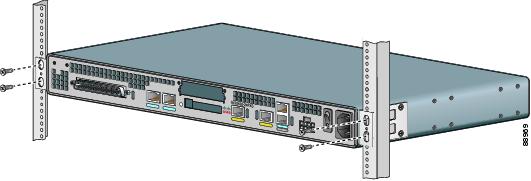
Step 2 ![]() Using screws that you provide, attach the chassis to the rack as shown in Figure 3-8.
Using screws that you provide, attach the chassis to the rack as shown in Figure 3-8.
Figure 3-8 Attaching the Chassis to the 19-Inch Rack
Wall-Mounting the Chassis
The following warning applies only when the unit is wall-mounted:
Warning ![]() This unit is intended to be mounted on a wall. Please read the wall-mounting instructions carefully before beginning installation. Failure to use the correct hardware or to follow the correct procedures could result in a hazardous situation to people and damage to the system. Statement 248
This unit is intended to be mounted on a wall. Please read the wall-mounting instructions carefully before beginning installation. Failure to use the correct hardware or to follow the correct procedures could result in a hazardous situation to people and damage to the system. Statement 248
Wall-Mounting the Cisco IAD2430, Cisco IAD2431, and Cisco IAD2432 IADs
To wall-mount the chassis, follow this procedure:
Step 1 ![]() Attach the short side of one bracket to the chassis, as shown in Figure 3-9, using two 6-32 x 1/4 slotted hex screws (provided). Be sure to use a plastic washer (provided) with each screw; the narrow end of the washer must fit into the bracket slot, facing the chassis.
Attach the short side of one bracket to the chassis, as shown in Figure 3-9, using two 6-32 x 1/4 slotted hex screws (provided). Be sure to use a plastic washer (provided) with each screw; the narrow end of the washer must fit into the bracket slot, facing the chassis.
Figure 3-9 Attaching the Brackets for Wall-Mounting
Step 2 ![]() Attach the second bracket to the opposite side of the chassis.
Attach the second bracket to the opposite side of the chassis.
Step 3 ![]() Attach the router to the wall using the brackets previously attached and using attachment hardware that you provide as follows:
Attach the router to the wall using the brackets previously attached and using attachment hardware that you provide as follows:
•![]() You can install a starter screw in the wall, and hook the bracket keyhole over the screw. This holds the unit in place for easy installation of the attachment screws.
You can install a starter screw in the wall, and hook the bracket keyhole over the screw. This holds the unit in place for easy installation of the attachment screws.
•![]() Attach both brackets to the wall.
Attach both brackets to the wall.
Note ![]() For attaching to a wall stud, each bracket requires two number 10 wood screws (round- or pan-head) with number 10 washers, or two number 10 washer-head screws. The screws must be long enough to penetrate at least 3/4-inch (20-mm) into the supporting wood or metal wall stud.
For attaching to a wall stud, each bracket requires two number 10 wood screws (round- or pan-head) with number 10 washers, or two number 10 washer-head screws. The screws must be long enough to penetrate at least 3/4-inch (20-mm) into the supporting wood or metal wall stud.
Note ![]() For hollow-wall mounting, each bracket requires two wall anchors with washers. Wall anchors and washers must be size number 10.
For hollow-wall mounting, each bracket requires two wall anchors with washers. Wall anchors and washers must be size number 10.
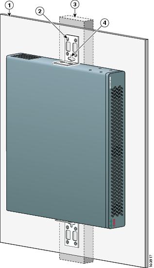
•![]() Figure 3-10 shows the orientation required for installation.
Figure 3-10 shows the orientation required for installation.
Figure 3-10 Wall-Mounting the Chassis
|
|
Wall |
|
Bracket |
|
|
Wall stud |
|
Keyhole for starter screw |
Wall-Mounting the Cisco IAD2435 IADs
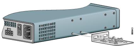
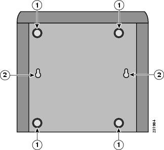
You can mount the router on a wall or other vertical surface by using the molded mounting brackets on the bottom of the router and two number-six, 3/4-inch (M3.5 x 20-mm) screws. You must provide the screws. Figure 3-11 shows the screw holes.
Figure 3-11 Screw Holes for Wall-Mounting the IAD2435
|
|
Rubber feet |
|
Screw holes |
The following conditions must be met when you mount the router:
•![]() Because you will use the LEDs as status and problem indicators, the LEDs on the front panel must face upward and must be easily visible.
Because you will use the LEDs as status and problem indicators, the LEDs on the front panel must face upward and must be easily visible.
•![]() The back panel must face downward to reduce strain on the cable connections.
The back panel must face downward to reduce strain on the cable connections.
•![]() The external 60-W power supply adapter must rest on a horizontal surface such as the floor or a table. If the power supply is not supported, it could place strain on the powersupply cable and cause it to disconnect from the connector on the router back panel.
The external 60-W power supply adapter must rest on a horizontal surface such as the floor or a table. If the power supply is not supported, it could place strain on the powersupply cable and cause it to disconnect from the connector on the router back panel.
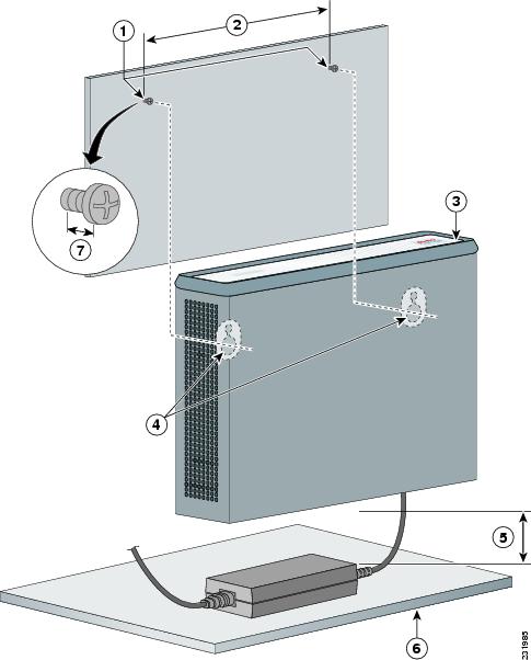
To wall-mount the Cisco IAD2435 IADs, follow these steps:
Step 1 ![]() Secure two screws 7 5/8 inches (19.35 centimeters) apart into a wall and 1/8 inch (0.32 centimeter) from the wall.
Secure two screws 7 5/8 inches (19.35 centimeters) apart into a wall and 1/8 inch (0.32 centimeter) from the wall.
Step 2 ![]() Hang the router on the screws as shown in Figure 3-12.
Hang the router on the screws as shown in Figure 3-12.
Step 3 ![]() Place the power supply on a horizontal surface.
Place the power supply on a horizontal surface.
Figure 3-12 Mounting the IAD2435 Router on a Wall
Desktop-Mounting the Chassis
Step 1 ![]() Verify that a suitable AC power outlet is available.
Verify that a suitable AC power outlet is available.
Step 2 ![]() Place the four rubber feet (from the accessory kit) in the four indentations on the underside of the chassis. This helps provide proper airflow through and around the chassis.
Place the four rubber feet (from the accessory kit) in the four indentations on the underside of the chassis. This helps provide proper airflow through and around the chassis.
Step 3 ![]() Place the Cisco IAD on the desktop.
Place the Cisco IAD on the desktop.
Setting the Cisco IAD2435 on a Desktop
You can place Cisco IAD2435 on a desktop.
Installing the Ground Connection
Warning ![]() This equipment must be grounded. Never defeat the ground conductor or operate the equipment in the absence of a suitably installed ground conductor. Contact the appropriate electrical inspection authority or an electrician if you are uncertain that suitable grounding is available. Statement 1024
This equipment must be grounded. Never defeat the ground conductor or operate the equipment in the absence of a suitably installed ground conductor. Contact the appropriate electrical inspection authority or an electrician if you are uncertain that suitable grounding is available. Statement 1024
Warning ![]() AC connected units must have a permanent ground connection in addition to the power cable ground wire. NEBS-compliant grounding satisfies this requirement. Statement 284
AC connected units must have a permanent ground connection in addition to the power cable ground wire. NEBS-compliant grounding satisfies this requirement. Statement 284
Warning ![]() This equipment needs to be grounded. Use a green and yellow 12 to 14 AWG ground wire to connect the host to earth ground during normal use. Statement 242
This equipment needs to be grounded. Use a green and yellow 12 to 14 AWG ground wire to connect the host to earth ground during normal use. Statement 242
Warning ![]() The importance of proper grounding cannot be overemphasized. It will minimize the potential for damage to your system and maximize safety at the system site. We recommend you consult a licensed electrician or your local electric utility company if you have any questions. Statement 269
The importance of proper grounding cannot be overemphasized. It will minimize the potential for damage to your system and maximize safety at the system site. We recommend you consult a licensed electrician or your local electric utility company if you have any questions. Statement 269
Warning ![]() A ground wire must always be a single piece of wire. Never splice two wires together for a ground. Corrosion and weathering can lead to a poor connection at the splice, making the ground ineffective and dangerous. Statement 270
A ground wire must always be a single piece of wire. Never splice two wires together for a ground. Corrosion and weathering can lead to a poor connection at the splice, making the ground ineffective and dangerous. Statement 270
Warning ![]() Use copper conductors only. Statement 1025
Use copper conductors only. Statement 1025
Warning ![]() Installation of the equipment must comply with local and national electrical codes. Statement 1074
Installation of the equipment must comply with local and national electrical codes. Statement 1074
You must connect the chassis to a reliable earth ground; the ground wire must be installed in accordance with local electrical safety standards.
•![]() For NEBS-compliant grounding, use size AWG 6 (13 mm2) wire and the ground lug provided in the accessory kit.
For NEBS-compliant grounding, use size AWG 6 (13 mm2) wire and the ground lug provided in the accessory kit.
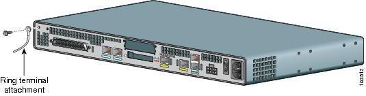
•![]() For NEC-compliant grounding, use size AWG 14 (2 mm2) or larger wire and an appropriate user-supplied ring terminal.
For NEC-compliant grounding, use size AWG 14 (2 mm2) or larger wire and an appropriate user-supplied ring terminal.
•![]() For EN/IEC 60950-compliant grounding, use size AWG 18 (1 mm2) or larger wire and an appropriate user-supplied ring terminal.
For EN/IEC 60950-compliant grounding, use size AWG 18 (1 mm2) or larger wire and an appropriate user-supplied ring terminal.
To ground the chassis, follow these steps:
Step 1 ![]() Locate a suitable ground location.
Locate a suitable ground location.
Tip ![]() Use a multimeter to measure the resistance between various ground locations, such as the following:
Use a multimeter to measure the resistance between various ground locations, such as the following:
•![]() Between the ground of a junction box (outlet) and the ground of a power tap
Between the ground of a junction box (outlet) and the ground of a power tap
•![]() Between the ground of a junction box and a metal water pipe
Between the ground of a junction box and a metal water pipe
•![]() Between the Cisco IAD chassis and the ground of a power tap
Between the Cisco IAD chassis and the ground of a power tap
•![]() Between the Cisco IAD chassis and the ground of a junction box
Between the Cisco IAD chassis and the ground of a junction box
A good ground connection should read between 0.0 and 0.5 ohm.
Step 2 ![]() Strip one end of the ground wire to the length required for the ground lug or terminal.
Strip one end of the ground wire to the length required for the ground lug or terminal.
•![]() For the NEBS ground lug—approximately 0.75 inch (20 millimeters)
For the NEBS ground lug—approximately 0.75 inch (20 millimeters)
•![]() For user-provided ring terminal—as required
For user-provided ring terminal—as required
Step 3 ![]() Crimp the ground wire to the ground lug or ring terminal, using a crimp tool of the appropriate size. (See Figure 3-13.)
Crimp the ground wire to the ground lug or ring terminal, using a crimp tool of the appropriate size. (See Figure 3-13.)
Figure 3-13 Crimping a Ground Lug onto the Ground Wire

Step 4 ![]() Attach the ground lug or ring terminal to the chassis as shown in Figure 3-14, Figure 3-15, or Figure 3-16. For the ground lug, use the two screws with captive locking washers provided. For a ring terminal, use one of the screws provided. Use a number 2 Phillips screwdriver, and tighten the screws to a torque of 8 to 10 in-lb (0.9 to 1.1 N-m).
Attach the ground lug or ring terminal to the chassis as shown in Figure 3-14, Figure 3-15, or Figure 3-16. For the ground lug, use the two screws with captive locking washers provided. For a ring terminal, use one of the screws provided. Use a number 2 Phillips screwdriver, and tighten the screws to a torque of 8 to 10 in-lb (0.9 to 1.1 N-m).
Note ![]() You can orient the crimped end of the ground lug in either direction (right or left).
You can orient the crimped end of the ground lug in either direction (right or left).
Figure 3-14 NEBS-Compliant Chassis Ground Connection Using Ground Lug
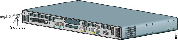
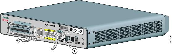
Figure 3-15 Ground Lug Location on the Cisco IAD2435 IAD
|
|
Grounding lug |
Figure 3-16 Chassis Ground Connection Using Ring Terminal
Step 5 ![]() Connect the other end of the ground wire to a grounding point at your site.
Connect the other end of the ground wire to a grounding point at your site.
Installing a WAN or Voice Card
The Cisco IAD2430 series IADs include a slot for a WAN interface card (WIC) or a voice interface card (VIC).
Note ![]() The Cisco IAD2435 router is a fixed-configuration router and does not support interface cards.
The Cisco IAD2435 router is a fixed-configuration router and does not support interface cards.
The following WICs and VICs (also used by the Cisco 2600 series and Cisco 3600 series routers) are supported in releases of the Cisco IAD2430 series IADs:
•![]() WIC-1T
WIC-1T
•![]() WIC-2T
WIC-2T
•![]() WIC-1DSU-T1/E1
WIC-1DSU-T1/E1
•![]() VIC2-2FXS
VIC2-2FXS
•![]() VIC2-4FXS
VIC2-4FXS
•![]() VIC2-2FXO
VIC2-2FXO
•![]() VIC2-4FXO
VIC2-4FXO
•![]() VIC2-2BRI-NT/TE
VIC2-2BRI-NT/TE
•![]() WIC-1ADSL
WIC-1ADSL
•![]() WIC-1SHDSL-V2
WIC-1SHDSL-V2
•![]() WIC-1ADSL-DG
WIC-1ADSL-DG
•![]() VWIC-2MFT-T1/E1
VWIC-2MFT-T1/E1
•![]() VWIC-2MFT-E1
VWIC-2MFT-E1
Warning ![]() For connections outside the building where the equipment is installed, the following ports must be connected through an approved network termination unit with integral circuit protection.
For connections outside the building where the equipment is installed, the following ports must be connected through an approved network termination unit with integral circuit protection.
FXS/T3/E3. Statement 1044
Note ![]() Contact your Cisco account representative for the most recent, supported cards.
Contact your Cisco account representative for the most recent, supported cards.
For detailed information on installing and connecting interface cards, see "Installing WAN and Voice Interface Cards in Cisco Modular Routers," in the Cisco Interface Cards Installation Guide, at the following URL:
http://www.cisco.com/univercd/cc/td/doc/product/access/acs_mod/cis2600/hw_inst/wic_inst/wic_doc/
index.htm
Always use an ESD-preventive wrist strap before handling cards.
To install a WIC or VIC, follow these steps:
Step 1 ![]() Use a number 2 Phillips screwdriver to remove the screws holding the metal plate over the card slot cover. Remove the plate.
Use a number 2 Phillips screwdriver to remove the screws holding the metal plate over the card slot cover. Remove the plate.
Step 2 ![]() Holding the interface card by the edges, line up the card with the guides on both sides of the slot.
Holding the interface card by the edges, line up the card with the guides on both sides of the slot.
Step 3 ![]() Insert the card in the slot. Push until it is firmly seated in the connector and the front panel of the card is flush with the back panel of the Cisco IAD.
Insert the card in the slot. Push until it is firmly seated in the connector and the front panel of the card is flush with the back panel of the Cisco IAD.
Step 4 ![]() Use the screwdriver to tighten the captive screws on the card.
Use the screwdriver to tighten the captive screws on the card.
Connecting Cables
Cisco IAD ports are color-coded for identification.
Warning ![]() Do not work on the system or connect or disconnect cables during periods of lightning activity. Statement 1001]
Do not work on the system or connect or disconnect cables during periods of lightning activity. Statement 1001]
Warning ![]() This product relies on the building's installation for short-circuit (overcurrent) protection. Ensure that the protective device is rated not greater than: 120 VAC, 15A (240 VAC, 10A international) Statement 1005
This product relies on the building's installation for short-circuit (overcurrent) protection. Ensure that the protective device is rated not greater than: 120 VAC, 15A (240 VAC, 10A international) Statement 1005
Warning ![]() To prevent accidental discharge in the event of a power line cross, route on-premise wiring away from power cables and off-premise wiring, or use a grounded shield to separate the on-premise wiring from the power cables and off-premise wiring. A power line cross is an event, such as a lightning strike, that causes a power surge. Off-premise wiring is designed to withstand power line crosses. On-premise wiring is protected from power line crosses by a device that provides overcurrent and overvoltage protection. Nevertheless, if the on-premise wiring is in close proximity to, or not shielded from, the off-premise wiring or power cables during a lightning strike or power surge, the on-premise wiring can carry a dangerous discharge to the attached interface, equipment, and nearby personnel. Statement 338
To prevent accidental discharge in the event of a power line cross, route on-premise wiring away from power cables and off-premise wiring, or use a grounded shield to separate the on-premise wiring from the power cables and off-premise wiring. A power line cross is an event, such as a lightning strike, that causes a power surge. Off-premise wiring is designed to withstand power line crosses. On-premise wiring is protected from power line crosses by a device that provides overcurrent and overvoltage protection. Nevertheless, if the on-premise wiring is in close proximity to, or not shielded from, the off-premise wiring or power cables during a lightning strike or power surge, the on-premise wiring can carry a dangerous discharge to the attached interface, equipment, and nearby personnel. Statement 338
Table 3-2 shows the results of the NEBS Type 1/3 power line cross tests performed on the Cisco IAD2430 series FXS ports.
Note ![]() The installation must comply with all applicable codes.
The installation must comply with all applicable codes.
LAN and Power Cables
The LAN and power cables and connections are described in Table 3-3 and shown in Figure 3-17 and Figure 3-18.
|
|
|
|
|
|---|---|---|---|
Fast Ethernet |
Yellow |
Fast Ethernet switch |
Straight-through Fast Ethernet cable (not included) |
Console |
Light blue |
PC or ASCII terminal communication (COM) port |
RJ-45-to-DB-9 console cable (included) |
Auxiliary |
Black |
Modem for remote access |
RJ-45-to-DB-25 auxiliary cable (included) |
Power (not shown) |
Power |
100-240 VAC, 50-60 Hz |
Grounding power cord (included)1 |
1 Power cables vary to meet local requirements. |
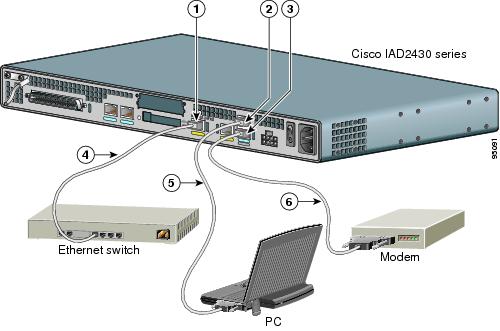
Figure 3-17 LAN and Administrative Access Connections
|
|
Fast Ethernet port |
|
Console port |
|
|
AUX port |
|
Fast Ethernet (straight-through) |
|
|
RJ-45-to-DB-9 console cable |
|
RJ-45-to-DB-25 auxiliary cable |
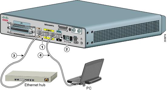
Figure 3-18 LAN, Administrative Access, and Connections (Cisco IAD2435 IAD)
|
|
Fast Ethernet port |
|
Serial port—console or auxiliary |
|
|
Fast Ethernet (straight-through) |
|
RJ-45-to-DB-9 console cable |
Connecting the Input Power
To connect input power to the Cisco IAD, use the procedure in this section.
Cable
The AC power cable is used for this application.
Procedure
Step 1 ![]() Connect the AC power cable (supplied) to the recessed power plug on the back of the concentrator.
Connect the AC power cable (supplied) to the recessed power plug on the back of the concentrator.
Step 2 ![]() Plug the cable into a power source with a voltage of 100 to 240 VAC.
Plug the cable into a power source with a voltage of 100 to 240 VAC.
Connecting Input Power on the Cisco IAD2435 IAD
To connect input power to the Cisco IAD2435, perform the following steps:
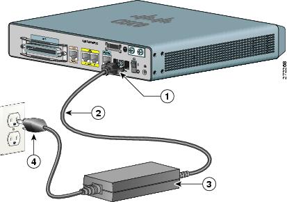
Step 1 ![]() Connect the router to an AC power outlet as shown in Figure 3-19.
Connect the router to an AC power outlet as shown in Figure 3-19.
Step 2 ![]() To secure the power cord to the router, attach the power lock clip to the power cord, and slide the clip to the end of the DC plug. See location 1 in Figure 3-19.
To secure the power cord to the router, attach the power lock clip to the power cord, and slide the clip to the end of the DC plug. See location 1 in Figure 3-19.
Figure 3-19 Connecting the External Power Supply to the Cisco IAD2435
|
|
Power lock clip |
|
Power cord |
|
|
Power adapter |
|
AC plug |
Connecting the Console Port to a PC or an ASCII Terminal
To connect the console port to a PC that is running terminal emulation software, use the procedure in this section.
Note ![]() The console port does not support hardware flow control.
The console port does not support hardware flow control.
Cable
Use an RJ-45-to-DB-9 console cable (see location 5 in Figure 3-17).
Procedure
Step 1 ![]() Connect the cable between the Cisco IAD console port and the serial port on the PC or ASCII terminal.
Connect the cable between the Cisco IAD console port and the serial port on the PC or ASCII terminal.
Step 2 ![]() Configure the terminal emulation software requirements:
Configure the terminal emulation software requirements:
•![]() 9600 baud
9600 baud
•![]() 8 data bits
8 data bits
•![]() 1 stop bit
1 stop bit
•![]() no parity
no parity
•![]() no flow control
no flow control
Connecting the Auxiliary Port to a Modem
To connect the auxiliary port to a modem, use the procedure in this section.
Cable
Use an RJ-45-to-DB-25 auxiliary cable (labeled Modem).
Procedure
Step 1 ![]() Connect the cable from the auxiliary port (black) to the DB-25 port on the modem. (See location 6 in Figure 3-17.)
Connect the cable from the auxiliary port (black) to the DB-25 port on the modem. (See location 6 in Figure 3-17.)
Step 2 ![]() Configure the modem:
Configure the modem:
a. ![]() Match the transmission speed of the auxiliary port (default is 9600 baud).
Match the transmission speed of the auxiliary port (default is 9600 baud).
b. ![]() Set the hardware flow control for Data Carrier Detect (DCD) and Data Terminal Ready (DTR) operation.
Set the hardware flow control for Data Carrier Detect (DCD) and Data Terminal Ready (DTR) operation.
Note ![]() The baud rate for the auxiliary (and console) port can be configured in software for 1200, 2400, 4800, 19200, 38400, 57600, or 115200.
The baud rate for the auxiliary (and console) port can be configured in software for 1200, 2400, 4800, 19200, 38400, 57600, or 115200.
Connecting the Fast Ethernet Port to the Fast Ethernet Switch
To connect a Fast Ethernet port to the Fast Ethernet switch, use the procedure in this section.
Cable
Use a straight-through Fast Ethernet cable (not included).
Procedure
Step 1 ![]() Connect the cable from a Fast Ethernet port to an available port on the Fast Ethernet switch. (See location 4 in Figure 3-17.)
Connect the cable from a Fast Ethernet port to an available port on the Fast Ethernet switch. (See location 4 in Figure 3-17.)
Step 2 ![]() Connect the second cable if it is required.
Connect the second cable if it is required.
Note ![]() Not all models have two ports.
Not all models have two ports.
WAN and Voice Cables
Warning ![]() For connections outside the building where the equipment is installed, the following ports must be connected through an approved network termination unit with integral circuit protection.
For connections outside the building where the equipment is installed, the following ports must be connected through an approved network termination unit with integral circuit protection.
FXS/T3/E3 Statement 1044
Note ![]() The following warning also applies to Cisco IAD2430 units that have an RJ-21 interface.
The following warning also applies to Cisco IAD2430 units that have an RJ-21 interface.
Warning ![]() Before opening the unit, disconnect the telephone-network cables to avoid contact with telephone-network voltages. Statement 1041
Before opening the unit, disconnect the telephone-network cables to avoid contact with telephone-network voltages. Statement 1041
Warning ![]() This equipment contains a ring signal generator (ringer), which is a source of hazardous voltage. Do not touch the RJ-11 (phone) port wires (conductors), the conductors of a cable connected to the RJ-11 port, or the associated circuit-board when the ringer is active. The ringer is activated by an incoming call. Statement 1042
This equipment contains a ring signal generator (ringer), which is a source of hazardous voltage. Do not touch the RJ-11 (phone) port wires (conductors), the conductors of a cable connected to the RJ-11 port, or the associated circuit-board when the ringer is active. The ringer is activated by an incoming call. Statement 1042
These cables and connections are described in Table 3-4 and shown in Figure 3-20.
Figure 3-20 WAN and Voice Connections
|
|
RJ-21 cable |
|
RJ-45 cable (through a patch panel) to central office (CO) |
|
|
RJ-48 straight-through cable |
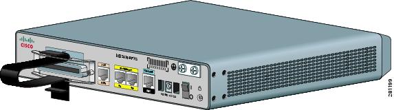
Connecting the RJ-21 Cable in the Velcro Harness
For the Cisco IAD2430 series models that have a Velcro harness available for the RJ-21 cable (see Figure 3-21), follow these steps:
Figure 3-21 Cisco IAD2430 Series RJ-21 Velcro Harness
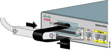
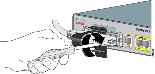
Step 1 ![]() Slip the RJ-21 cable connector through the Velcro strap (see Figure 3-22).
Slip the RJ-21 cable connector through the Velcro strap (see Figure 3-22).
Figure 3-22 Sliding the RJ-21 Cable Through the Velcro Harness
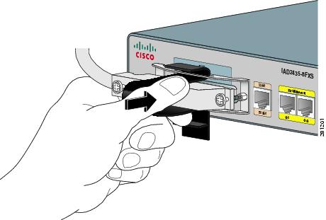
Step 2 ![]() Push the male RJ-21 cable connector into the slot of the female RJ-21 connection on the router. Push the male RJ-21 cable firmly until the RJ-21 security clips are firmly seated (see Figure 3-23).
Push the male RJ-21 cable connector into the slot of the female RJ-21 connection on the router. Push the male RJ-21 cable firmly until the RJ-21 security clips are firmly seated (see Figure 3-23).
Figure 3-23 Pushing the RJ-21 Cable in to the Cisco IAD2435 IAD
Step 3 ![]() Use a number 2 (flat or Phillips screwdriver) to attach the captive screws on the RJ-21 male connector (see Figure 3-24).
Use a number 2 (flat or Phillips screwdriver) to attach the captive screws on the RJ-21 male connector (see Figure 3-24).
Figure 3-24 Tightening the Captive Screws
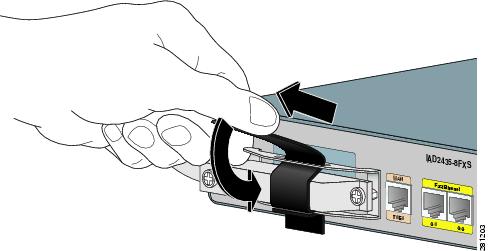
Step 4 ![]() Pull the Velcro strap up until tight, then down and affix the strap to other Velcro side (see Figure 3-25).
Pull the Velcro strap up until tight, then down and affix the strap to other Velcro side (see Figure 3-25).
Figure 3-25 Tightening the Velcro Strap
Connecting a Serial Interface Port to a CSU/DSU or a Synchronous Modem
Use the procedure in this section to connect the serial interface port to a CSU/DSU or to a synchronous modem.
The serial port (S0) can operate as follows:
•![]() DTE or DCE with the following signaling:
DTE or DCE with the following signaling:
–![]() EIA/TIA-232
EIA/TIA-232
–![]() EIA-TIA-449
EIA-TIA-449
–![]() V.35
V.35
–![]() X.21
X.21
•![]() DTE only with EIA/TIA -530 signaling
DTE only with EIA/TIA -530 signaling
Note ![]() DTE ports require external clocking provided by a DCE device such as a CSU/DSU.
DTE ports require external clocking provided by a DCE device such as a CSU/DSU.
Cable
The type of cable you connect to the serial port automatically sets the port for DTE or DCE operation and establishes the signaling standard.
Procedure
Use the procedure in this section to connect external equipment to the Cisco 2430 series IAD.
Step 1 ![]() Connect the appropriate serial interface cable between the WAN serial port and the serial port connector (see Figure 3-26).
Connect the appropriate serial interface cable between the WAN serial port and the serial port connector (see Figure 3-26).
Figure 3-26 Serial Port Connection
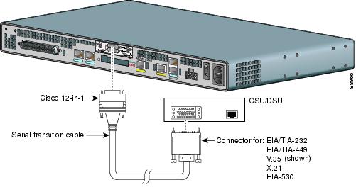
Step 2 ![]() Connect the external equipment (CSU/DSU or other serial device).
Connect the external equipment (CSU/DSU or other serial device).
Connecting a T1/E1-WAN Port to the Network Demarcation Device
To connect the T1/E1 port to a network demarcation device, use the procedure in this section.
Warning ![]() To avoid electric shock, do not connect safety extra-low voltage (SELV) circuits to telephone-network voltage (TNV) circuits. LAN ports contain SELV circuits, and WAN ports contain TNV circuits. Some LAN and WAN ports both use RJ-45 connectors. Use caution when connecting cables. Statement 1021
To avoid electric shock, do not connect safety extra-low voltage (SELV) circuits to telephone-network voltage (TNV) circuits. LAN ports contain SELV circuits, and WAN ports contain TNV circuits. Some LAN and WAN ports both use RJ-45 connectors. Use caution when connecting cables. Statement 1021
Warning ![]() Hazardous network voltages are present in WAN ports regardless of whether power to the router is OFF or ON. To avoid electric shock, use caution when working near WAN ports. When detaching cables, detach the end away from the router first. Statement 1026
Hazardous network voltages are present in WAN ports regardless of whether power to the router is OFF or ON. To avoid electric shock, use caution when working near WAN ports. When detaching cables, detach the end away from the router first. Statement 1026
Note ![]() The T1/E1-WAN port has a built-in CSU/DSU for connecting to a service provider's network interface.
The T1/E1-WAN port has a built-in CSU/DSU for connecting to a service provider's network interface.
Cable
Use an RJ-48 T1/E1 cable (not included).
Procedure
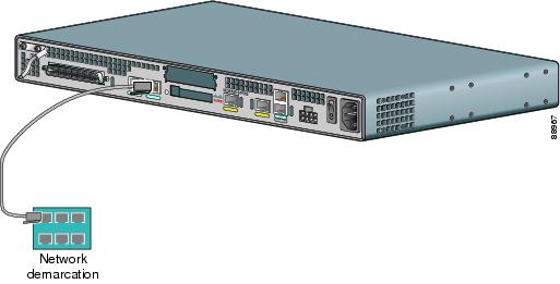
Step 1 ![]() Connect the RJ-48 T1/E1 cable to the T1-WAN port (marked T1-WAN on a light-green label).
Connect the RJ-48 T1/E1 cable to the T1-WAN port (marked T1-WAN on a light-green label).
Step 2 ![]() Connect the RJ-48C/CA81A jack to the network demarcation device (telco demarcation or equivalent).
Connect the RJ-48C/CA81A jack to the network demarcation device (telco demarcation or equivalent).
(See Figure 3-27.)
Figure 3-27 T1/E1 Port to Network Connection
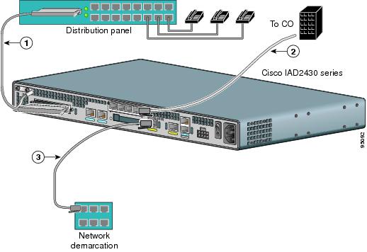
Connecting the Analog Voice Interface to a Distribution Panel
To connect the multiport analog voice interface to a distribution panel, which connects to telephones, faxes, or analog PBX equipment, use the procedure in this section.
Cable
Use an RJ-21 cable with Amphenol 50-pin connectors (not included).
Warning ![]() This equipment contains a ring signal generator (ringer), which is a source of hazardous voltage. Do not touch the RJ-11 (phone) port wires (conductors), the conductors of a cable connected to the RJ-11 port, or the associated circuit-board when the ringer is active. The ringer is activated by an incoming call. Statement 1042
This equipment contains a ring signal generator (ringer), which is a source of hazardous voltage. Do not touch the RJ-11 (phone) port wires (conductors), the conductors of a cable connected to the RJ-11 port, or the associated circuit-board when the ringer is active. The ringer is activated by an incoming call. Statement 1042
Procedure
Step 1 ![]() Connect the RJ-21 cable from the analog voice multiport to the distribution panel. See Figure 3-28.
Connect the RJ-21 cable from the analog voice multiport to the distribution panel. See Figure 3-28.
Figure 3-28 Analog Voice Connection
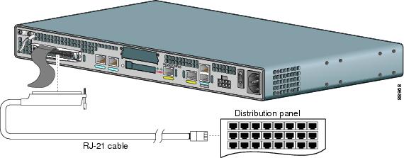
Step 2 ![]() Use the strap to secure the cable in place.
Use the strap to secure the cable in place.
Connecting the Digital Voice Port to a T1/E1-PBX
To connect the digital voice port to a digital PBX, use the procedure in this section.
Cable
Use an RJ-48 T1/E1 cable (not included).
Procedure
Step 1 ![]() Connect the RJ-48 T1/E1 cable to the T1/E1 port. See Figure 3-29.
Connect the RJ-48 T1/E1 cable to the T1/E1 port. See Figure 3-29.
Figure 3-29 Digital Voice Connection
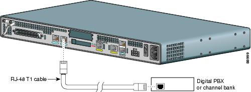
Step 2 ![]() Connect the RJ-48 jack to the digital telephone equipment (PBX).
Connect the RJ-48 jack to the digital telephone equipment (PBX).
Ports, Connectors, and Pinouts
Table 3-5 summarizes the cable connections between Cisco IADs and the network and user interfaces.
Remote Terminal Connections (If Applicable)
If you are configuring a Cisco IAD from a remote location, connect the modem and the remote PC or terminal to the telephone network as described in this section.
Connecting to a Modem
To connect the local modem and the remote modem to live telephone outlets, use standard telephone cables.
Connecting to a Remote PC
To link a Cisco IAD to a remote PC, follow these steps.
Note ![]() The remote PC must be running terminal emulation software.
The remote PC must be running terminal emulation software.
Step 1 ![]() Connect the remote PC and modem.
Connect the remote PC and modem.
Step 2 ![]() Set the PC terminal emulation software requirements:
Set the PC terminal emulation software requirements:
•![]() 9600 baud
9600 baud
•![]() 8 data bits
8 data bits
•![]() 1 stop bit
1 stop bit
•![]() no parity
no parity
•![]() no flow control
no flow control
Step 3 ![]() Key in and dial the telephone number of the Cisco IAD external modem.
Key in and dial the telephone number of the Cisco IAD external modem.
Connecting to a Remote ASCII Terminal
To link a Cisco IAD to a remote ASCII terminal, such as a VT100, follow these steps:
Step 1 ![]() Connect the remote ASCII terminal and modem.
Connect the remote ASCII terminal and modem.
Step 2 ![]() Set the terminal requirements:
Set the terminal requirements:
•![]() 9600 baud
9600 baud
•![]() 8 data bits
8 data bits
•![]() 1 stop bit
1 stop bit
•![]() no parity
no parity
•![]() no flow control
no flow control
Step 3 ![]() Key in the telephone number of the Cisco IAD external modem, or, if you are using a Hayes-compatible modem, enter ATDT and the number to be dialed.
Key in the telephone number of the Cisco IAD external modem, or, if you are using a Hayes-compatible modem, enter ATDT and the number to be dialed.
Connecting Backup Power
Cisco IAD2430 series IADs can be installed with optional backup power. Backup power to a DC-powered IAD is provided by a battery backup system; see the "Connecting a Backup Battery to a DC-Powered IAD" section section for connection instructions. Backup power to an AC-powered IAD is provided by an uninterruptible power supply (UPS); see the "Connecting an Uninteruptible Power Supply UPS to an AC-Powered Cisco IAD2430 Series IAD" section for connection instructions.
Note ![]() UPS functionality is not available on the IAD2435 IAD.
UPS functionality is not available on the IAD2435 IAD.
See Table 3-6 for the maximum power requirements for each Cisco IAD2430 IAD model.
Connecting a Backup Battery to a DC-Powered IAD
Connect a 12-volt backup battery to the DC input connector on your Cisco IAD2430 series router. Before you install a backup battery, be sure to read the installation instructions for the backup battery equipment.
Figure 3-30 shows a setup using an external backup battery.
Note ![]() Figure 3-30 shows one possible setup; please review your backup battery documentation before you set up your system.
Figure 3-30 shows one possible setup; please review your backup battery documentation before you set up your system.
Figure 3-30 Connecting a Backup Battery to a DC-Powered Cisco IAD
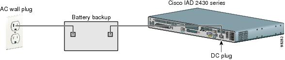
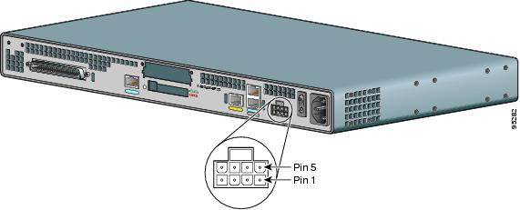
Figure 3-31 shows the DC power connector. See Table 3-7 for pinout information for the DC power connector on Cisco IAD2430 series IADs.
Figure 3-31 DC Power Connector
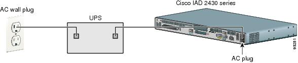
Connecting an Uninteruptible Power Supply UPS to an AC-Powered Cisco IAD2430 Series IAD
Connect an uninterruptible power supply (UPS) to the AC input on your Cisco IAD2430 series IAD. Before you install a UPS, be sure to read the installation instructions for the UPS.
Note ![]() UPS functionality is not available on the Cisco IAD2435 IAD.
UPS functionality is not available on the Cisco IAD2435 IAD.
Figure 3-32 shows a setup using a UPS.
Note ![]() Figure 3-32 shows one possible setup; please review your UPS documentation before you set up your system.
Figure 3-32 shows one possible setup; please review your UPS documentation before you set up your system.
Figure 3-32 Connecting a UPS to an AC-Powered Cisco IAD
 Feedback