Cisco 800M Series ISR Hardware Installation Guide
Bias-Free Language
The documentation set for this product strives to use bias-free language. For the purposes of this documentation set, bias-free is defined as language that does not imply discrimination based on age, disability, gender, racial identity, ethnic identity, sexual orientation, socioeconomic status, and intersectionality. Exceptions may be present in the documentation due to language that is hardcoded in the user interfaces of the product software, language used based on RFP documentation, or language that is used by a referenced third-party product. Learn more about how Cisco is using Inclusive Language.
- Updated:
- June 8, 2015
Chapter: Connecting the Router
Connecting the Router
This chapter describes how to connect the Cisco C841M-4X/K9 and Cisco C841M-8X/K9 ISR to Ethernet devices and a network. The section contains the following topics:
- Preparing to Connect the Router
- Connecting a PC, Server, or Workstation
- Connecting an External Ethernet Switch
- Connecting a Terminal or PC to the Console Port
- Verifying Connections

Note![]() For compliance and safety information, see Regulatory Compliance and Safety Information for Cisco 800 Series Routers.
For compliance and safety information, see Regulatory Compliance and Safety Information for Cisco 800 Series Routers.
Preparing to Connect the Router
Before you connect the router to the devices, install the router according to the instructions in the “Installing the Router” section.
Preventing Damage to the Router
To prevent damage to your router, follow these guidelines when connecting devices to your router:

- If you must supply your own cable, see the “Router Specifications” section for cabling specifications. If this appendix does not provide specifications for a particular cable, we strongly recommend ordering the cable from Cisco.
Connecting a PC, Server, or Workstation
To connect a PC (or other Ethernet devices) to an Ethernet switch port, follow these steps:
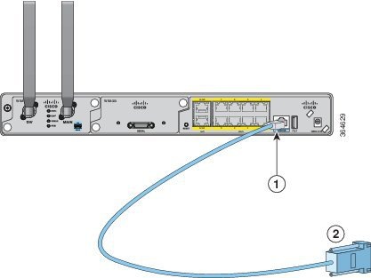
Step 1![]() Connect one end of the Ethernet cable to an Ethernet switch port on the router, as shown in Figure 3-1.
Connect one end of the Ethernet cable to an Ethernet switch port on the router, as shown in Figure 3-1.
Note![]() The connections remain the same for a 4 port module.
The connections remain the same for a 4 port module.
Figure 3-1 Connecting a Server, PC, or Workstation

|
|
|
||
|
|
|
Step 2![]() Connect the other end of the cable to the RJ-45 port on the network interface card (NIC) that is installed in the PC, server, or workstation.
Connect the other end of the cable to the RJ-45 port on the network interface card (NIC) that is installed in the PC, server, or workstation.
Step 3![]() (Optional) Connect additional servers, PCs, or workstations to the other Ethernet switch ports.
(Optional) Connect additional servers, PCs, or workstations to the other Ethernet switch ports.
Note![]() Use the Cisco Configuration Express to configure the Internet connection settings. See Cisco Configuration Professional Quick Start Guide for more information.
Use the Cisco Configuration Express to configure the Internet connection settings. See Cisco Configuration Professional Quick Start Guide for more information.
Connecting an External Ethernet Switch
Cisco C841M-4X/K9 ISR has four LAN ports and Cisco C841M-8X/K9 ISR has eight LAN ports. If you are using Cisco C841M-4X/K9 ISR, you can connect four PCs to the router. If you need to connect more than four PCs, you can add Ethernet connections to the router by connecting an external Ethernet switch to the Ethernet switch on the router. Similarly, if you are using Cisco C841M-8X/K9 ISR, use an external Ethernet switch to connect more than eight PCs.
To connect an external Ethernet switch to an Ethernet switch port on the router, perform these steps:
Step 1![]() Connect one end of the Ethernet cable to an Ethernet switch port on the router, as shown in Figure 3-2.
Connect one end of the Ethernet cable to an Ethernet switch port on the router, as shown in Figure 3-2.
Note![]() The connections remain the same for a 4 port module.
The connections remain the same for a 4 port module.
Figure 3-2 Connecting to an Ethernet Switch

|
|
|
CAT5 Ethernet cable, RJ-45–to–RJ-45, connecting to an external Ethernet switch port |
|
|
|
|
Step 2![]() Connect the other end of the cable to the available port on the Ethernet switch to add additional Ethernet connections.
Connect the other end of the cable to the available port on the Ethernet switch to add additional Ethernet connections.
Step 3![]() Turn on the Ethernet switch.
Turn on the Ethernet switch.
Connecting a Terminal or PC to the Console Port
Connect a terminal or PC to the Console port either to configure the software by using the CLI or to troubleshoot problems with the router.
To connect a terminal or PC to the console port on the router and access the CLI, follow these steps:
Step 1![]() Connect the RJ-45 end of a DB-9-to-RJ-45 serial cable to the RJ-45 Console port on the router.
Connect the RJ-45 end of a DB-9-to-RJ-45 serial cable to the RJ-45 Console port on the router.
Note![]() The connections remain the same for a 4 port module.
The connections remain the same for a 4 port module.
Figure 3-3 shows the RJ-45 end of the serial cable connected to the Console port on the router.
Figure 3-3 Connecting a Terminal or PC to the Console Port
|
|
|
Step 2![]() Connect the DB-9 end of the DB-9-to-RJ-45 serial cable to the COM port on your laptop or PC.
Connect the DB-9 end of the DB-9-to-RJ-45 serial cable to the COM port on your laptop or PC.
Note![]() Some laptops and PCs do not come with DB-9 serial port connectors and may require a USB-to-serial port adapter.
Some laptops and PCs do not come with DB-9 serial port connectors and may require a USB-to-serial port adapter.
Step 3![]() To communicate with the router, start a terminal emulator application.
To communicate with the router, start a terminal emulator application.
Verifying Connections
To verify that all devices are properly connected to the router, first turn on all the connected devices, and then check the LEDs. For more information on LEDs on the Cisco 800M Series ISR, see LEDs.
 Feedback