General Description
The Cisco 809 Integrated Services Router (IR809), part of the Cisco Integrated Services Routers Generation 2 (ISR G2) Family, is designed as a next generation ruggedized fixed form factor router. It is a small-form factor router with LTE, for use in ATM, POS, Telemetry, Billboards, Enterprise Fleet markets, Utilities and other SCADA (Supervisory Control and Data Acquisition) environments.
 Note |
The documentation set for this product strives to use bias-free language. For purposes of this documentation set, bias-free is defined as language that does not imply discrimination based on age, disability, gender, racial identity, ethnic identity, sexual orientation, socioeconomic status, and intersectionality. Exceptions may be present in the documentation due to language that is hardcoded in the user interfaces of the product software, language used based on RFP documentation, or language that is used by a referenced third-party product. |
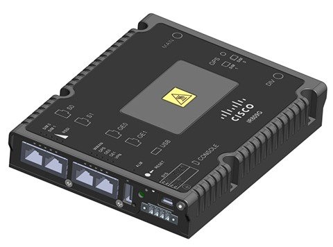
The following figure shows the IR809.
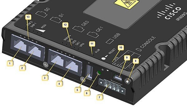
The following figure shows the front panel details of the Cisco IR809.
|
1 |
S0 RS232 DCE/RS485 Combo Port |
8 |
Grounding Point |
|
2 |
S1 RS232 DTE only |
9 |
Mini type-B USB console/debug port |
|
3 |
GE0 (10/100/1000) |
10 |
SYS LED |
|
4 |
GE1 (10/100/1000) |
11 |
Alarm LED |
|
5 |
USB 2.0 (Type-A Host Port) |
12 |
WAN/WWAN LEDs |
|
6 |
RESET Button |
13 |
SIM Card LEDs |
|
7 |
DC Power/Alarm Connector |
Note |
LEDs are viewable from the top and from the front of the IR809. |
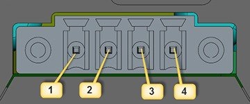
The following figure shows the back panel details of the Cisco IR809.

|
1 |
DIV TNC connector for 4G Modem |
|
2 |
SMA connector for GPS |
|
3 |
SIM0 and SIM1 Card Slots |
|
4 |
MAIN TNC connector for 4G Modem |
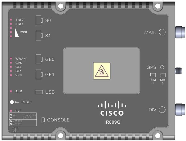
The following figure shows the top cover details of the Cisco IR809.
LEDs
The following table describes the LEDs for the Cisco 809 ISR.
|
LED |
Activity |
Description |
||
|---|---|---|---|---|
|
SYS |
Power and System Status |
In normal operating mode, after system boots. (typically about 2 minutes) Off — No power Green Steady on — Router is reachable, and all interfaces are up and functioning properly Green Flashing — Router is reachable, and no interface is in a failed state Amber Steady on — Router is unreachable (An external interface of the router, that prevents the router from being remotely managed, is in a critical failed state) Amber Flashing — Router is reachable, but at least one of the interfaces is in a non-critical failed state (functionality of that interface is affected) In bootup mode (during the first 60 seconds after powerup)Green Steady on — Router is bootingy Amber Steady on — Router has a system hardware failure |
||
|
ALM |
Alarm Input Status |
Off — Normal operation Red - Alarm State on the Alarm Input |
||
|
VPN_OK |
VPN |
Off — No VPN tunnel Steady Green — At least one VPN tunnel is up |
||
|
GE0 (10/100/1000)WAN 0 GE0 (10/100/1000)WAN 1 |
Link Status |
Off — No link Steady Green — Link is up Flashing — Transmitting and Receiving data |
||
|
GPS |
GPS Status |
Off — GPS not configured On — GPS configured Slow Flash — GPS Acquiring in Standalone GPS Fast Flash — GPS Acquiring in Assisted GPS
|
||
|
WWAN |
Wireless WAN Activity |
Off — Modem not powered on
On — Modem is powered on and connected but not transmitting or receiving
Slow Blink — Modem is powered on and searching for connection
Fast Blink — Modem is transmitting or receiving. |
||
|
RSSI |
Received Signal Strength Indication |
The RSSI LEDs are a 3 LED bar graph to indicate signal strength. Their functionality is described in the RSSI LEDs table below. | ||
|
SIM0/SIM1 |
SIM cards |
Off — No USIM
Green — USIM installed and active |
|
RSSI |
RSSI (2) |
RSSI (1) |
RSSI (0) |
|---|---|---|---|
|
Green |
Green |
Green/Amber |
|
|
< -110dBm |
Off |
Off |
Off |
|
-110 to -90dBm |
Off |
Off |
On - Amber |
|
-90 to -75dBm |
Off |
Off |
On - Green |
|
-75 to -60dBm |
Off |
On - Green |
On - Green |
|
> -60dBm |
On - Green |
On - Green |
On - Green |
 Feedback